EP3605436B1 - Procédé de localisation de défauts de phase dans un micro-réseau et controlleur - Google Patents
Procédé de localisation de défauts de phase dans un micro-réseau et controlleur Download PDFInfo
- Publication number
- EP3605436B1 EP3605436B1 EP18306031.8A EP18306031A EP3605436B1 EP 3605436 B1 EP3605436 B1 EP 3605436B1 EP 18306031 A EP18306031 A EP 18306031A EP 3605436 B1 EP3605436 B1 EP 3605436B1
- Authority
- EP
- European Patent Office
- Prior art keywords
- feeder
- current
- phase
- tripping
- feeders
- Prior art date
- Legal status (The legal status is an assumption and is not a legal conclusion. Google has not performed a legal analysis and makes no representation as to the accuracy of the status listed.)
- Active
Links
Images


Classifications
-
- G—PHYSICS
- G01—MEASURING; TESTING
- G01R—MEASURING ELECTRIC VARIABLES; MEASURING MAGNETIC VARIABLES
- G01R31/00—Arrangements for testing electric properties; Arrangements for locating electric faults; Arrangements for electrical testing characterised by what is being tested not provided for elsewhere
- G01R31/08—Locating faults in cables, transmission lines, or networks
- G01R31/088—Aspects of digital computing
-
- G—PHYSICS
- G01—MEASURING; TESTING
- G01R—MEASURING ELECTRIC VARIABLES; MEASURING MAGNETIC VARIABLES
- G01R31/00—Arrangements for testing electric properties; Arrangements for locating electric faults; Arrangements for electrical testing characterised by what is being tested not provided for elsewhere
- G01R31/08—Locating faults in cables, transmission lines, or networks
- G01R31/081—Locating faults in cables, transmission lines, or networks according to type of conductors
- G01R31/086—Locating faults in cables, transmission lines, or networks according to type of conductors in power transmission or distribution networks, i.e. with interconnected conductors
-
- H—ELECTRICITY
- H02—GENERATION; CONVERSION OR DISTRIBUTION OF ELECTRIC POWER
- H02H—EMERGENCY PROTECTIVE CIRCUIT ARRANGEMENTS
- H02H1/00—Details of emergency protective circuit arrangements
- H02H1/0007—Details of emergency protective circuit arrangements concerning the detecting means
-
- H—ELECTRICITY
- H02—GENERATION; CONVERSION OR DISTRIBUTION OF ELECTRIC POWER
- H02H—EMERGENCY PROTECTIVE CIRCUIT ARRANGEMENTS
- H02H3/00—Emergency protective circuit arrangements for automatic disconnection directly responsive to an undesired change from normal electric working condition with or without subsequent reconnection ; integrated protection
- H02H3/26—Emergency protective circuit arrangements for automatic disconnection directly responsive to an undesired change from normal electric working condition with or without subsequent reconnection ; integrated protection responsive to difference between voltages or between currents; responsive to phase angle between voltages or between currents
- H02H3/28—Emergency protective circuit arrangements for automatic disconnection directly responsive to an undesired change from normal electric working condition with or without subsequent reconnection ; integrated protection responsive to difference between voltages or between currents; responsive to phase angle between voltages or between currents involving comparison of the voltage or current values at two spaced portions of a single system, e.g. at opposite ends of one line, at input and output of apparatus
-
- H—ELECTRICITY
- H02—GENERATION; CONVERSION OR DISTRIBUTION OF ELECTRIC POWER
- H02H—EMERGENCY PROTECTIVE CIRCUIT ARRANGEMENTS
- H02H7/00—Emergency protective circuit arrangements specially adapted for specific types of electric machines or apparatus or for sectionalised protection of cable or line systems, and effecting automatic switching in the event of an undesired change from normal working conditions
- H02H7/22—Emergency protective circuit arrangements specially adapted for specific types of electric machines or apparatus or for sectionalised protection of cable or line systems, and effecting automatic switching in the event of an undesired change from normal working conditions for distribution gear, e.g. bus-bar systems; for switching devices
-
- H—ELECTRICITY
- H02—GENERATION; CONVERSION OR DISTRIBUTION OF ELECTRIC POWER
- H02H—EMERGENCY PROTECTIVE CIRCUIT ARRANGEMENTS
- H02H7/00—Emergency protective circuit arrangements specially adapted for specific types of electric machines or apparatus or for sectionalised protection of cable or line systems, and effecting automatic switching in the event of an undesired change from normal working conditions
- H02H7/26—Sectionalised protection of cable or line systems, e.g. for disconnecting a section on which a short-circuit, earth fault, or arc discharge has occured
-
- H—ELECTRICITY
- H02—GENERATION; CONVERSION OR DISTRIBUTION OF ELECTRIC POWER
- H02J—ELECTRIC POWER NETWORKS; CIRCUIT ARRANGEMENTS OR SYSTEMS FOR SUPPLYING OR DISTRIBUTING ELECTRIC POWER; SYSTEMS FOR STORING ELECTRIC ENERGY
- H02J3/00—Circuit arrangements for AC mains or AC distribution networks
- H02J3/001—Arrangements for handling faults or abnormalities, e.g. emergencies or contingencies
- H02J3/0012—Arrangements for handling faults or abnormalities, e.g. emergencies or contingencies characterised by the contingency detection means in AC networks, e.g. using phasor measurement units [PMU], synchrophasors or contingency analysis
-
- H—ELECTRICITY
- H02—GENERATION; CONVERSION OR DISTRIBUTION OF ELECTRIC POWER
- H02J—ELECTRIC POWER NETWORKS; CIRCUIT ARRANGEMENTS OR SYSTEMS FOR SUPPLYING OR DISTRIBUTING ELECTRIC POWER; SYSTEMS FOR STORING ELECTRIC ENERGY
- H02J13/00—Circuit arrangements for providing remote monitoring or remote control of equipment in a power distribution network
- H02J13/13—Circuit arrangements for providing remote monitoring or remote control of equipment in a power distribution network characterised by the transmission of data to equipment in the power network
-
- H—ELECTRICITY
- H02—GENERATION; CONVERSION OR DISTRIBUTION OF ELECTRIC POWER
- H02J—ELECTRIC POWER NETWORKS; CIRCUIT ARRANGEMENTS OR SYSTEMS FOR SUPPLYING OR DISTRIBUTING ELECTRIC POWER; SYSTEMS FOR STORING ELECTRIC ENERGY
- H02J13/00—Circuit arrangements for providing remote monitoring or remote control of equipment in a power distribution network
- H02J13/18—Circuit arrangements for providing remote monitoring or remote control of equipment in a power distribution network characterised by the remotely-controlled equipment, e.g. converters or transformers
- H02J13/333—Circuit arrangements for providing remote monitoring or remote control of equipment in a power distribution network characterised by the remotely-controlled equipment, e.g. converters or transformers the equipment forming part of substations
-
- H—ELECTRICITY
- H02—GENERATION; CONVERSION OR DISTRIBUTION OF ELECTRIC POWER
- H02J—ELECTRIC POWER NETWORKS; CIRCUIT ARRANGEMENTS OR SYSTEMS FOR SUPPLYING OR DISTRIBUTING ELECTRIC POWER; SYSTEMS FOR STORING ELECTRIC ENERGY
- H02J13/00—Circuit arrangements for providing remote monitoring or remote control of equipment in a power distribution network
- H02J13/18—Circuit arrangements for providing remote monitoring or remote control of equipment in a power distribution network characterised by the remotely-controlled equipment, e.g. converters or transformers
- H02J13/34—Circuit arrangements for providing remote monitoring or remote control of equipment in a power distribution network characterised by the remotely-controlled equipment, e.g. converters or transformers the equipment being switches, relays or circuit breakers
- H02J13/36—Circuit arrangements for providing remote monitoring or remote control of equipment in a power distribution network characterised by the remotely-controlled equipment, e.g. converters or transformers the equipment being switches, relays or circuit breakers specially adapted for protection systems
-
- H—ELECTRICITY
- H02—GENERATION; CONVERSION OR DISTRIBUTION OF ELECTRIC POWER
- H02J—ELECTRIC POWER NETWORKS; CIRCUIT ARRANGEMENTS OR SYSTEMS FOR SUPPLYING OR DISTRIBUTING ELECTRIC POWER; SYSTEMS FOR STORING ELECTRIC ENERGY
- H02J2105/00—Networks for supplying or distributing electric power characterised by their spatial reach or by the load
- H02J2105/10—Local stationary networks having a local or delimited stationary reach
-
- H—ELECTRICITY
- H02—GENERATION; CONVERSION OR DISTRIBUTION OF ELECTRIC POWER
- H02J—ELECTRIC POWER NETWORKS; CIRCUIT ARRANGEMENTS OR SYSTEMS FOR SUPPLYING OR DISTRIBUTING ELECTRIC POWER; SYSTEMS FOR STORING ELECTRIC ENERGY
- H02J3/00—Circuit arrangements for AC mains or AC distribution networks
- H02J3/38—Arrangements for feeding a single network from two or more generators or sources in parallel; Arrangements for feeding already energised networks from additional generators or sources in parallel
- H02J3/381—Dispersed generators
-
- Y—GENERAL TAGGING OF NEW TECHNOLOGICAL DEVELOPMENTS; GENERAL TAGGING OF CROSS-SECTIONAL TECHNOLOGIES SPANNING OVER SEVERAL SECTIONS OF THE IPC; TECHNICAL SUBJECTS COVERED BY FORMER USPC CROSS-REFERENCE ART COLLECTIONS [XRACs] AND DIGESTS
- Y02—TECHNOLOGIES OR APPLICATIONS FOR MITIGATION OR ADAPTATION AGAINST CLIMATE CHANGE
- Y02E—REDUCTION OF GREENHOUSE GAS [GHG] EMISSIONS, RELATED TO ENERGY GENERATION, TRANSMISSION OR DISTRIBUTION
- Y02E40/00—Technologies for an efficient electrical power generation, transmission or distribution
- Y02E40/70—Smart grids as climate change mitigation technology in the energy generation sector
-
- Y—GENERAL TAGGING OF NEW TECHNOLOGICAL DEVELOPMENTS; GENERAL TAGGING OF CROSS-SECTIONAL TECHNOLOGIES SPANNING OVER SEVERAL SECTIONS OF THE IPC; TECHNICAL SUBJECTS COVERED BY FORMER USPC CROSS-REFERENCE ART COLLECTIONS [XRACs] AND DIGESTS
- Y02—TECHNOLOGIES OR APPLICATIONS FOR MITIGATION OR ADAPTATION AGAINST CLIMATE CHANGE
- Y02E—REDUCTION OF GREENHOUSE GAS [GHG] EMISSIONS, RELATED TO ENERGY GENERATION, TRANSMISSION OR DISTRIBUTION
- Y02E60/00—Enabling technologies; Technologies with a potential or indirect contribution to GHG emissions mitigation
-
- Y—GENERAL TAGGING OF NEW TECHNOLOGICAL DEVELOPMENTS; GENERAL TAGGING OF CROSS-SECTIONAL TECHNOLOGIES SPANNING OVER SEVERAL SECTIONS OF THE IPC; TECHNICAL SUBJECTS COVERED BY FORMER USPC CROSS-REFERENCE ART COLLECTIONS [XRACs] AND DIGESTS
- Y04—INFORMATION OR COMMUNICATION TECHNOLOGIES HAVING AN IMPACT ON OTHER TECHNOLOGY AREAS
- Y04S—SYSTEMS INTEGRATING TECHNOLOGIES RELATED TO POWER NETWORK OPERATION, COMMUNICATION OR INFORMATION TECHNOLOGIES FOR IMPROVING THE ELECTRICAL POWER GENERATION, TRANSMISSION, DISTRIBUTION, MANAGEMENT OR USAGE, i.e. SMART GRIDS
- Y04S10/00—Systems supporting electrical power generation, transmission or distribution
- Y04S10/12—Monitoring or controlling equipment for energy generation units, e.g. distributed energy generation [DER] or load-side generation
-
- Y—GENERAL TAGGING OF NEW TECHNOLOGICAL DEVELOPMENTS; GENERAL TAGGING OF CROSS-SECTIONAL TECHNOLOGIES SPANNING OVER SEVERAL SECTIONS OF THE IPC; TECHNICAL SUBJECTS COVERED BY FORMER USPC CROSS-REFERENCE ART COLLECTIONS [XRACs] AND DIGESTS
- Y04—INFORMATION OR COMMUNICATION TECHNOLOGIES HAVING AN IMPACT ON OTHER TECHNOLOGY AREAS
- Y04S—SYSTEMS INTEGRATING TECHNOLOGIES RELATED TO POWER NETWORK OPERATION, COMMUNICATION OR INFORMATION TECHNOLOGIES FOR IMPROVING THE ELECTRICAL POWER GENERATION, TRANSMISSION, DISTRIBUTION, MANAGEMENT OR USAGE, i.e. SMART GRIDS
- Y04S40/00—Systems for electrical power generation, transmission, distribution or end-user application management characterised by the use of communication or information technologies, or communication or information technology specific aspects supporting them
- Y04S40/12—Systems for electrical power generation, transmission, distribution or end-user application management characterised by the use of communication or information technologies, or communication or information technology specific aspects supporting them characterised by data transport means between the monitoring, controlling or managing units and monitored, controlled or operated electrical equipment
Definitions
- the present invention relates to a method for locating electrical faults in a microgrid, and in particular to a microgrid including distributed renewable and non-renewable energy sources.
- a microgrid is basically a local electrical grid intended to generate and distribute electrical power in regions that are isolated and far from large electrical energy generation stations, such as, for example, islands, mountainous regions or desert areas.
- the microgrid principle is also applicable when it is desired for a building, neighborhood, campus or other entity connected to a wide distribution grid to manage the generation of its energy differently and e.g. increase its capacity for resilience.
- a microgrid is an electrical installation integrating renewable and non-renewable energy sources and/or storage that is able to operate in both on-grid mode, that is connected to a utility grid, and in off-grid mode.
- Microgrids may be made up of various kind of energy resources that are spatially distributed and disconnected from a main i.e. utility grid, also referred to as distributed energy resources DER. Such microgrids are set up as autonomous islands for energy supply. These distributed resources may include renewable energy resources, such as photovoltaic cells, solar panels and wind turbines. They further may include engine-generator energy resources, such as fuel consuming engines or turbines. And they may comprise energy storage facilities for locally storing energy, which may include chemical type storage such as batteries or mechanical type storage such as flywheels. As common for electrical installations, the various local parts are referred to as feeder bays or feeders in short, which are connected to busbars having a single voltage in order to distribute the energy.
- distributed energy resources may include renewable energy resources, such as photovoltaic cells, solar panels and wind turbines. They further may include engine-generator energy resources, such as fuel consuming engines or turbines. And they may comprise energy storage facilities for locally storing energy, which may include chemical type storage such as batteries or mechanical type storage
- the microgrid may functionally be split into a resource plane, a network plane and a control plane.
- the resource plane includes the distributed energy resources of renewable, generator and storage resources.
- each of the different types of energy resources may be collectively organized in distinct plants, such as a renewable plant, a generator set plant and a storage plant.
- the network plane includes the distribution network and loads to which energy is supplied.
- the control plane includes the local controllers for each plant of energy resource types and an overall microgrid central controller for centrally controlling the coordination between the different energy plants.
- renewable energy sources operate as DC sources
- these are equipped with inverters in order to provide an AC signal that may be coupled to the grid.
- the AC signals provided by the inverters need to match the grid in both phase and magnitude.
- the connections to the grid are supervised / monitored via Protection Relays operating electrical switch gear equipment, such as circuit breakers, enabling to disconnect one or more of the energy resources from the grid. This would for example be required in case of short circuit currents occurring in either the microgrid grid or the grid.
- inverters of these renewable resources are characterized by low short circuit capacity.
- inverter-based sources limit the short-circuit currents to values not much higher than the nominal current to protect the inverter itself.
- Gopalan Sachit et al (IEEE PES ISGT Europe 2013, IEEE, 06 October 2013, pages 1-5, XP032549962 ) proposes two microgrid protection schemes consisting of high impedance fault detection, directional protection, backup protection modules and either an undervoltage or a differential module.
- this object is achieved by a method according to claim 1 .
- each fault location is characterized by a unique "signature" - defined by a unique current flow and current magnitude at each point of the installation, which may be used to identify the fault location.
- the proposed method uses a centralized software-based system communicating with the protection and measurement units at every feeder and all voltage relays installed at source busbars.
- on-grid mode protection may be assured by overcurrent protection devices as known.
- off-grid mode the presence of fault is identified by the software system as follows: Identifying presence of a fault through detection of a voltage drop at at least one source busbar. Determining the fault location through analysis of the current magnitudes of all feeders of each busbar. Once the fault is localized, a tripping order may be sent to the nearest switchgear equipment, such as circuit breaker, to disconnect the faulty part from sources feeding the located fault.
- a single line diagram is shown representing an example of a microgrid.
- the microgrid has six busbars 30 - 35 connecting various loads 36 and different energy resources 37.
- the energy resources 37 may be non-renewable, such as fueled generators, or renewable, such as photovoltaic cells.
- Each connection may be referred to as a feeder bay or feeder in short.
- the microgrid further has voltage measurement devices U0 - U5 and current measurement devices indicated by I G1 - I G4 for generator currents and I L1 - I L4 and I L21 -I L23 for load currents.
- Each current measurement device is associated with one feeder, being either incoming or outgoing.
- Each feeder may be connected and disconnected by a corresponding circuit breaker 39 - 52 from the respective busbar.
- busbar 30 has one circuit breaker 39 controlling connection to one energy resource 37, one circuit breaker 40 controlling connection to busbar 32 connected to further energy resources 37, one circuit breaker 42 controlling connection to busbar 31 connected to loads 36, and one circuit breaker41 controlling connection to busbar 33 and further parts of the microgrid.
- Additional circuit breakers 43 and 44 may be used to further control connection of busbars 31 and 32 respectively.
- the feeders of additional busbars 31, 32 are also provided with further circuit breakers 54a-c, and 55a-d.
- the microgrid is a three phase system, so there are three phase-to-phase voltages Uab, Ubc and Uca and three phase-to-neutral voltages Uan, Ubn and Ucn.
- the voltage measurement devices U0 - U5 measure each of these voltages for the respective busbars 30 - 35.
- the current measurement devices measure the current in each phase for the respective feeders.
- each circuit breaker 39 - 55 may have a control element associated with it for controlling connection.
- the circuit breakers are remotely controlled individually via a single central control/protection element (not shown).
- the control elements may be trip units.
- the control elements may be a protection relays.
- a surveillance area 38 for which the voltage of the busbars and the current measurements of all connected feeders are available.
- the surveillance area 38 includes al busbars that are connected to at least two sources. And current measurements for all incoming source feeders and outgoing load feeders should be available.
- the position or state, open or closed, of all relevant circuit breakers 39 - 52 within the surveillance area should be known.
- These elements determine a grid topology of the microgrid.
- the general grid topology may be known in advance, e.g. from the design phase or engineering process, and may usually be available from a file stored within a control system of the microgrid.
- the topology may be e.g.
- the storage and access may be arranged by a central controller, e.g. the microgrid central controller of Fig. 1 .
- the position of all circuit breakers would also be available from the same central controller.
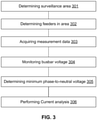
- the method includes determining 301 a surveillance area 38 of the microgrid having at least two busbar connected to at least two sources 37. As mentioned, the surveillance area depends on the position of circuit breakers and includes all busbars connected to at least two energy sources. The method further includes determining all incoming and outgoing feeders 302 of the surveillance area. Then acquiring current measurement data 303, the measurement data including current magnitude for all feeders. The measurement data may be acquired continuously, or only when triggered on detecting a phase fault. The measurement data may include the current magnitude for each phase of all feeders or only for the phase of all feeders for which a voltage dip was detected.
- the method further includes monitoring the one or more busbars 304 in the surveillance area 38 for a voltage dip for all six phase voltages. These include three phase-to-phase voltages U AB , U BC , U CA and three phase-to-neutral voltages V AN , V BN , V CN . When a voltage dip is detected on one of the at least two monitored busbars, a phase having a minimum phase-to-neutral voltage 305 value is determined. For this faulty phase, the phase having the minimum phase-to-neutral voltage, current analysis 306 is performed.
- Performing current analysis 306 includes performing an area current analysis for at least the surveillance area 38 and, depending on the outcome of the area current analysis, further performing busbar current analysis for each individual busbar within the surveillance area 38.
- the busbar current analysis of each individual busbar is preferably performed simultaneously, in order to reduce the amount of time required for locating the phase fault.
- the part of the microgrid being monitored, the surveillance area 38 in Fig. 2 may be regarded as node to which Kirchhoff's current laws apply. Hence, all incoming currents should be equal to all outgoing currents or, equated differently, the sum of all incoming and outgoing current should be zero.
- I Gx ⁇ ⁇ I Lx 0 wherein I Gx refers to measured source currents, and wherein I Lx refers to measured load currents.
- performing area current analysis includes applying Kirchhoff's current law to determine if a detected phase fault is located outside and downstream of the surveillance area 38.
- Applying Kirchhoff's law includes assigning opposite signs to incoming i.e. source and outgoing i.e. load currents and summing all current magnitudes to locate a phase fault if the sum is not equal to zero. If Kirchhoff's law remains valid, i.e. the sum is zero, or at least nearly zero, so the outgoing currents match the incoming currents, a first circuit breaker 51, 47, 46, or 42 corresponding to one of the outgoing feeders having a maximum current value is tripped. The tripping of the first circuit breaker may be performed after a time delay to ensure a time discrimination with one or more downstream circuit breakers which are not monitored and not controlled.
- the tripping of the first circuit breaker 42 may be preceded or even precluded by tripping one of the circuit breakers 43, 54a-c downstream of the circuit breaker 42. This may be done when current measurements thereof are available, as it may be determined if a single feeder located further downstream may be the sole cause of the phase fault. In the example of Fig. 2 this is the case for current measurement devices I L21 , I L22 , and I L23 on the feeders of downstream busbar 31. And it is checked whether any of these measured currents I L21 -I L23 matches the outgoing feeder current I L2 . Moreover, if one of the circuit breakers 43, 54a-c downstream is tripped, circuit breaker 51, 47, 46, 42 may not be required to trip and hence, be prevented from tripping.
- the outgoing current I L2 of busbar 30, which is the incoming current of busbar 31 may be compared to each of the outgoing currents I L21 , I L22 , and I L23 of busbar 31. And if one of these phase currents is equal to the incoming current I L2 , preferably within a 10% margin, prior to or even instead of tripping the main circuit breaker 42, one of the circuit breakers 54a-c of the corresponding downstream level outgoing feeder may be tripped with a pre-determined time delay.
- a 10% margin is preferably applied to take in account measurement accuracy, errors and potential phase shifts between currents. If the margin exceeds 10%, the phase fault is located between the busbar levels, and the circuit breakers 42 and / or 43 are tripped.
- the sum of the currents having the lowest or minimum value indicates the direction of the possible fault current.
- the absolute value of each sum may be determined.
- the origin of the fault may be any of the sources 37 connected to busbar 32 via the respective circuit breakers 55a-d. Accordingly, one of the corresponding circuit breakers 40 or 44 could be tripped, under consideration of a certain time delay, in accordance with the time discrimination rules between circuit breakers 40 or 44 and circuit breaker 55.
- the short-circuit or fault current may be traced through the surveillance area. Meaning that the direction indicated by the minimum summed value per busbar can be traced to an incoming feeder.
- the minimum value for busbar 30 would direct to I G5
- the minimum summed value for busbar 33 would direct to I G7
- the fault could be traced to one of the incoming feeders associated with I G1 or I G2 as indicated by the minimum summed value for busbar 34.
- either circuit breaker 50 or 52 could be tripped. If the voltage is not recovered, the fault is on the busbar 34 itself, and all the circuit breakers of the incoming feeders are tripped.
- phase fault could be located on one of the busbars itself. In that case, all other incoming feeders of the busbar for which already the first circuit breaker was tripped are also tripped. Thus, if the minimum summed value resulted in tripping circuit breaker 52 in Fig. 2 , now further circuit breakers 49 and 50 are tripped to clear the phase fault. In this case, though the minimum summed value provided an indication of the fault location, the fault was not cleared; indicating that the fault is located on the busbar itself.
- the method as disclosed may be performed by a central control element having one or more processing units as part of the control plane of the microgrid.
- Shown in Fig. 4 is an example of a flowchart for implementing an example of the method.
- the control element executing the method will be connected with all the measurement devices and trip units for communication.
- the grid topology will be available from the control element.
- the flow chart starts by defining 401 the surveillance area of the microgrid, as described above, and include all busbars connected to two or more sources. Defining the surveillance area further includes identifying all source feeders and load feeders present in the surveillance area. During execution, the grid topology 402 will be checked for changes in busbars, feeders, loads and sources; and if required will re-define the surveillance area. Furthermore, while in operation, the control element will continuously acquire measurement data which includes current magnitude for all source feeders and load feeders and voltage levels of the busbars.
- the busbars in the surveillance area are monitored 403 for a voltage dip in one of phase-to-phase or phase-to-neutral voltages, as acquired by the control element. On detecting a voltage dip, it is determined which of three possible phases is a defect phase by identifying the phase 404 having the minimum phase-to-neutral voltage. To allow for some measurement error and phase shift between currents when checking compliance of Kirchhoff's law, the difference between the sum of source currents S-Igx and opposite load currents S-IIx is compared 405 against a 5% threshold of the sum of the source currents: 0.05 * S-Igx.
- the load feeder Y having the maximum current value "max I LY " is identified 406 and the grid topology is checked for the availability of downstream current measurements 407. If none are available, the trip unit corresponding to the identified feeder Y is tripped 408. If downstream current measurements are available, and the current measurement for one of the downstream feeders matches the "max I LY ", the trip unit corresponding to that downstream feeder is tripped 409. Either way, this should result in clearance 410 of the phase fault. Once cleared, the process returns to the beginning of the flow chart 401.
- each source feeder is respectively considered as a potential origin of the phase fault and accordingly different equations are drawn up on the assumption that one of the respective source feeders actually operates as a load feeder.
- the resulting set of equations is evaluated to identify the source feeder per busbar that possibly feeds the phase fault.
- the equations provide per potentially contributing source feeder a sum of source and load currents.
- the source feeder having the minimum summed value directs to fault location, and accordingly a trace of source feeders having minimum summed values can be tracked.
- the trip unit corresponding to that source feeder is tripped 413. If the identified source feeder does not direct outside the surveillance area 412, but directs to opposite ends of an internal feeder 414, trip units corresponding to both ends of that internal feeder are tripped 415. If after tripping of the trip units the voltage at the busbar is not recovered 416, all trip units of the associated busbar are tripped 417. In the end, the phase fault should be cleared 418 and the processing starts again at the begin of the flow chart 401.
Landscapes
- Physics & Mathematics (AREA)
- Engineering & Computer Science (AREA)
- General Physics & Mathematics (AREA)
- Power Engineering (AREA)
- Mathematical Physics (AREA)
- Theoretical Computer Science (AREA)
- Remote Monitoring And Control Of Power-Distribution Networks (AREA)
- Emergency Protection Circuit Devices (AREA)
Claims (11)
- Procédé mis en œuvre par ordinateur pour localiser des défauts de phase dans un microréseau en mode hors réseau, comprenant :la définition (301) d'une zone de surveillance (38) du microréseau comportant au moins deux barres de distribution(30, 33, 34) à surveiller ;l'évaluation (302) de toutes les alimentations de source et alimentations de charge de la zone de surveillance (38) ;l'acquisition de données de mesure (303), les données comprenant l'amplitude du courant pour toutes les alimentations de source et alimentations de charge ;la surveillance desdites au moins deux barres de distribution (304) dans la zone de surveillance pour détecter une chute de tension dans l'une des tensions de phase à phase ou de phase à neutre comme indication d'un défaut de phase ; etlors de la détection d'une chute de tension :la détermination d'une phase défectueuse présentant une tension de phase à neutre minimale (305) ;caractérisé parla réalisation d'une analyse de courant (306) pour la phase de défaut, dans lequel l'exécution de l'analyse de courant (306) comprend :l'application de la loi des courants de Kirchhoff pour déterminer si un défaut de phase détecté est situé à l'extérieur et/ou en aval de la zone de surveillance (38) ; etsi la loi de Kirchhoff est valide, le déclenchement d'un coupe-circuit principal (42, 46, 47, 51) correspondant à une alimentation de charge présentant une valeur de courant maximale,et dans lequel la réalisation de l'analyse de courant (306) comprend en outre :si la loi de Kirchhoff n'est pas valide,la détermination pour chaque barre de distribution (30, 33, 34) dans la zone de surveillance (38) d'au moins une alimentation de source minimale ayant une valeur de courant sommée minimale de toutes les alimentations de source de la barre de distribution respective, etla détermination d'une trace des alimentations de source minimales sur toute la zone de surveillance ; etsi la trace pointe vers un emplacement de défaut extérieur à la zone de surveillance (38), le déclenchement d'un coupe-circuit (39, 40, 44, 50, 52) correspondant à l'alimentation de source à l'extrémité de la trace ; et/ousi la trace pointe vers un emplacement de défaut au niveau d'une alimentation interne à l'intérieur de la zone de surveillance (38), le déclenchement de coupe-circuits (41, 45, 48, 49) de l'alimentation interne aux deux extrémités de la trace.
- Procédé selon la revendication 1, dans lequel la loi de Kirchhoff est valide avec une première marge d'erreur de 5% ou moins.
- Procédé selon la revendication 1 ou 2, dans lequel l'exécution de l'analyse de courant comprend en outre :si la loi de Kirchhoff est valide, et si des données de mesure de courant sont disponibles pour une alimentation à un niveau aval, si un courant de phase de l'alimentation aval est égal, avec une deuxième marge d'erreur, au courant de l'alimentation de charge présentant le courant maximal, alors :avant ou au lieu de déclencher le coupe-circuit principal (42) correspondant au fait que l'alimentation de charge présente la valeur de courant maximale, le déclenchement de l'alimentation de charge de niveau aval correspondante avec un temps de retard.
- Procédé selon la revendication 3, dans lequel la deuxième marge d'erreur est de 10% ou moins.
- Procédé selon l'une quelconque des revendications 2 - 4, dans lequel la réalisation de l'analyse de courant comprend en outre :
si, après un temps de retard prédéterminé par rapport au déclenchement d'un ou plusieurs coupe-circuits, une perturbation de tension est toujours présente, alors le déclenchement de tous les coupe-circuits (39, 40, 41, 42, 43, 44, 45, 46, 47, 48, 49, 50, 51, 52) de toutes les alimentations de la barre de distribution respective (30, 33, 34). - Procédé selon la revendication 1, dans lequel la réalisation de l'analyse de courant comprend en outre :l'attribution de signes opposés à des courants de source (IGX) et à des courants de charge (ILX) ;la sommation de toutes les amplitudes de courant pour localiser un défaut de phase à l'intérieur ou à l'extérieur de la zone de surveillance (38) ;si les courants sommés sont nuls à une première marge près, la détermination du fait que l'alimentation de charge à l'extérieur de la zone de surveillance présente une valeur de courant maximale dans l'une des trois phases ; etsi aucune mesure de courant n'est disponible pour une alimentation aval, le déclenchement avec un certain temps de retard d'un coupe-circuit (42, 46, 47, 51) correspondant à l'alimentation de charge déterminée présentant la valeur de courant maximale ; ousi des mesures de courant aval (IL21, IL22, IL23) sont disponibles pour des alimentations plus en aval, etsi une mesure de courant aval est égale, à une deuxième marge près, au courant de l'alimentation de charge déterminée présentant la valeur de courant maximale, le déclenchement de l'alimentation de charge aval correspondante avec un temps de retard ; ousi aucune des mesures de courant aval n'est égale, à une marge de 10 % près, au courant de l'alimentation de charge déterminée présentant la valeur de courant maximale, alors le déclenchement d'un coupe-circuit (54a, 54b, 54c) correspondant à l'alimentation de charge déterminée présentant la valeur de courant maximale.
- Procédé selon la revendication 6, dans lequel la réalisation de l'analyse de courant comprend en outre :si les courants sommés sont non nuls à la première marge près,la détermination, pour chaque barre de distribution (30, 33, 34) dans la zone de surveillance (38), d'au moins une alimentation de source minimale présentant une valeur de courant sommée minimale de toutes les alimentations de source de la barre de distribution respective, etle suivi d'une trace des alimentations de source minimales sur toute la zone de surveillance ;si la trace pointe vers une source d'alimentation en dehors de la zone de surveillance, le déclenchement d'un coupe-circuit (39, 40, 44, 50, 52) correspondant à l'alimentation de source à l'extrémité de la trace ; si la trace pointe vers un emplacement de défaut au niveau d'une source d'alimentation interne à l'intérieur de la zone de surveillance, le déclenchement des coupe-circuits (41, 45, 48, 49) de la source d'alimentation interne aux deux extrémités de la trace.
- Procédé selon la revendication 7, dans lequel la réalisation de l'analyse de courant comprend en outre :
si, après un temps de retard prédéterminé suivant le déclenchement d'un ou plusieurs coupe-circuits, une perturbation de tension est toujours présente, alors le déclenchement de tous les coupe-circuits (39, 40, 41, 42, 43, 44, 45, 46, 47, 48, 49, 50, 51, 52) de toutes les alimentations de la barre de distribution correspondante (30, 33, 34). - Produit de programme d'ordinateur, comprenant un programme d'ordinateur comportant des instructions qui, lorsqu'elles sont exécutées sur au moins un processeur, amènent ledit au moins un processeur à mettre en œuvre le procédé selon l'une quelconque des revendications 1 - 8.
- Support lisible par ordinateur sur lequel est stocké un code exécutable par ordinateur destiné à être exécuté par des processeurs d'ordinateur commandant un microréseau, dans lequel l'exécution des instructions du code exécutable amène les processeurs d'ordinateur à mettre en œuvre le procédé mis en œuvre par ordinateur selon les revendications 1 - 8 sur le microréseau.
- Contrôleur central de microréseau, comprenant :des moyens de communication pour collecter des données de mesure à partir de dispositifs de mesure et échanger des données de commande avec des dispositifs de commande ;au moins un processeur d'ordinateur pour exécuter des instructions ; etun produit de programme d'ordinateur, comprenant un programme d'ordinateur comportant des instructions qui, lorsqu'elles sont exécutées sur ledit au moins un processeur, amènent ledit au moins un processeur d'ordinateur à mettre en œuvre le procédé selon l'une quelconque des revendications 1 - 8.
Priority Applications (3)
| Application Number | Priority Date | Filing Date | Title |
|---|---|---|---|
| EP18306031.8A EP3605436B1 (fr) | 2018-07-31 | 2018-07-31 | Procédé de localisation de défauts de phase dans un micro-réseau et controlleur |
| US16/418,062 US11209474B2 (en) | 2018-07-31 | 2019-05-21 | Method for locating phase faults in a microgrid |
| CN201910525126.3A CN110783946B (zh) | 2018-07-31 | 2019-06-18 | 用于定位微电网中相故障的方法 |
Applications Claiming Priority (1)
| Application Number | Priority Date | Filing Date | Title |
|---|---|---|---|
| EP18306031.8A EP3605436B1 (fr) | 2018-07-31 | 2018-07-31 | Procédé de localisation de défauts de phase dans un micro-réseau et controlleur |
Publications (2)
| Publication Number | Publication Date |
|---|---|
| EP3605436A1 EP3605436A1 (fr) | 2020-02-05 |
| EP3605436B1 true EP3605436B1 (fr) | 2022-03-09 |
Family
ID=63144944
Family Applications (1)
| Application Number | Title | Priority Date | Filing Date |
|---|---|---|---|
| EP18306031.8A Active EP3605436B1 (fr) | 2018-07-31 | 2018-07-31 | Procédé de localisation de défauts de phase dans un micro-réseau et controlleur |
Country Status (3)
| Country | Link |
|---|---|
| US (1) | US11209474B2 (fr) |
| EP (1) | EP3605436B1 (fr) |
| CN (1) | CN110783946B (fr) |
Families Citing this family (11)
| Publication number | Priority date | Publication date | Assignee | Title |
|---|---|---|---|---|
| CN111668817A (zh) * | 2020-06-09 | 2020-09-15 | 广东电网有限责任公司东莞供电局 | 一种阻断故障电流的光伏并网控制方法和系统 |
| US11588323B2 (en) | 2020-09-03 | 2023-02-21 | Commonwealth Associates, Inc. | Method and apparatus for locating faults in an islanded microgrid |
| US11719736B2 (en) * | 2020-12-07 | 2023-08-08 | S&C Electric Company | Method for locating and isolating a fault in a power distribution network |
| US11616358B2 (en) | 2020-12-07 | 2023-03-28 | S&C Electric Company | Fault isolation |
| CN113078649B (zh) * | 2021-03-31 | 2021-11-16 | 贵州电网有限责任公司 | 基于灵敏度分析和设备故障率的电网事故事件等级预判系统和方法 |
| CN115568290A (zh) * | 2021-05-03 | 2023-01-03 | 西门子股份公司 | 特别是用于数据中心的冗余电源及用于其运行的方法和计算机程序 |
| CN114217144B (zh) * | 2021-12-06 | 2023-09-08 | 广州天加环境控制设备有限公司 | 一种三相永磁同步电机运行中缺相的检测方法 |
| CN116626434B (zh) * | 2022-08-03 | 2025-05-23 | 湖南科技大学 | 一种基于dbn与粗糙集神经网络的配电网缺相故障诊断方法 |
| CN116826674B (zh) * | 2023-06-19 | 2024-06-11 | 国网湖北省电力有限公司电力科学研究院 | 一种适配控制模式切换的光储充群直流微电网极间故障保护方法 |
| US20250226656A1 (en) * | 2024-01-08 | 2025-07-10 | Ge Infrastructure Technology Llc | System and method for protecting a plurality of distributed generation resources |
| CN119070366B (zh) * | 2024-07-15 | 2025-04-18 | 国家电网有限公司华东分部 | 受电端电网电压强度的评估方法及装置、介质、终端 |
Family Cites Families (20)
| Publication number | Priority date | Publication date | Assignee | Title |
|---|---|---|---|---|
| EP1223652A1 (fr) * | 2001-01-16 | 2002-07-17 | Abb Research Ltd. | Procédé pour localiser une faute dans un réseau de distribution d'énergie |
| EP1478985B1 (fr) * | 2002-02-25 | 2019-04-03 | ABB Schweiz AG | Modules d'echantillonnage de donnees et de transmission destines a des systemes de distribution electrique |
| GB0606904D0 (en) * | 2006-04-06 | 2006-05-17 | Rolls Royce Plc | Electrical Fault Detection |
| US7542256B2 (en) * | 2006-12-29 | 2009-06-02 | General Electric Company | Relay device and corresponding method |
| WO2009012800A1 (fr) * | 2007-07-24 | 2009-01-29 | Siemens Aktiengesellschaft | Appareil de protection et procédé de fonctionnement d'un appareil de protection |
| US8405944B2 (en) * | 2007-10-09 | 2013-03-26 | Schweitzer Engineering Laboratories Inc | Distributed bus differential protection using time-stamped data |
| EP2194656B1 (fr) * | 2008-12-03 | 2014-06-25 | ABB Research Ltd. | Système de gestion d'un réseau d'énergie électrique |
| WO2012155975A1 (fr) * | 2011-05-19 | 2012-11-22 | Abb Technology Ag | Système et procédé de protection d'un réseau de distribution électrique |
| CN102611086B (zh) * | 2012-03-27 | 2015-01-07 | 许继电气股份有限公司 | 一种区域配电网集中式网络化保护系统及方法 |
| CN102818972A (zh) * | 2012-08-30 | 2012-12-12 | 天津大学 | 一种微电网故障定位方法 |
| FR2996691B1 (fr) * | 2012-10-05 | 2015-11-13 | Schneider Electric Ind Sas | Plan de protection ameliore contre les defauts monophases pour les reseaux de distribution moyenne tension |
| CN102967842B (zh) * | 2012-10-24 | 2014-11-05 | 重庆大学 | 一种电子式电流互感器的渐变性故障在线诊断方法 |
| CN103701106B (zh) * | 2013-12-11 | 2017-04-05 | 清华大学 | 一种适用于微电网的继电保护方法 |
| CA2885117C (fr) * | 2014-03-17 | 2022-12-06 | Open Access Technology International, Inc. | Controle de micro-reseau fonde sur le nuage |
| US9923371B1 (en) * | 2014-08-13 | 2018-03-20 | Rosendin Electric, Inc. | Shared resource system |
| EP3327453B1 (fr) * | 2016-11-23 | 2023-12-27 | General Electric Technology GmbH | Procédé de localisation d'un défaut dans un système de transmission de puissance |
| KR101904815B1 (ko) * | 2016-12-21 | 2018-10-15 | 효성중공업 주식회사 | Ess용 pcs 및 pcs 운전 방법 |
| EP3460935B1 (fr) * | 2017-09-22 | 2021-06-16 | ABB Schweiz AG | Procédé et système de protection d'alimentation dans un réseau d'alimentation électrique |
| US10269509B1 (en) * | 2018-05-16 | 2019-04-23 | The Florida International University Board Of Trustees | Methods and techniques for protection of microgrid energy management system with distributed storage |
| US11211800B2 (en) * | 2018-06-08 | 2021-12-28 | The Regents Of The University Of California | Method and system for locating the source of events in power distribution systems using distribution-level PMU data |
-
2018
- 2018-07-31 EP EP18306031.8A patent/EP3605436B1/fr active Active
-
2019
- 2019-05-21 US US16/418,062 patent/US11209474B2/en active Active
- 2019-06-18 CN CN201910525126.3A patent/CN110783946B/zh active Active
Also Published As
| Publication number | Publication date |
|---|---|
| EP3605436A1 (fr) | 2020-02-05 |
| US20200041561A1 (en) | 2020-02-06 |
| CN110783946B (zh) | 2024-05-24 |
| CN110783946A (zh) | 2020-02-11 |
| US11209474B2 (en) | 2021-12-28 |
Similar Documents
| Publication | Publication Date | Title |
|---|---|---|
| EP3605436B1 (fr) | Procédé de localisation de défauts de phase dans un micro-réseau et controlleur | |
| US11205892B2 (en) | Method for locating phase faults in a microgrid | |
| Azeroual et al. | Fault location and detection techniques in power distribution systems with distributed generation: Kenitra City (Morocco) as a case study | |
| Memon et al. | A critical review of AC Microgrid protection issues and available solutions | |
| US8884467B2 (en) | System and method for protecting an electrical power grid | |
| US11721975B2 (en) | System and method for use with microgrids having inverter-based distributed generators | |
| Sarathkumar et al. | A technical review on classification of various faults in smart grid systems | |
| EP3334000B1 (fr) | Procédé de commande d'un micro-réseau de distribution d'énergie électrique | |
| Cordova et al. | Fault location identification in smart distribution networks with distributed generation | |
| Shahzad et al. | A comprehensive review of protection schemes for distributed generation | |
| Isa et al. | Evaluation on non-detection zone of passive islanding detection techniques for synchronous distributed generation | |
| Billinton et al. | Composite generation and transmission system adequacy evaluation including protection system failure modes | |
| Mirsaeidi et al. | Review and Analysis of Existing Protection Strategies for Micro-grids. | |
| Kamyab et al. | Development of a hybrid method to assess grid-related LOOP scenarios for an NPP | |
| Sujatha et al. | Enhancing Microgrid Protection through Adaptive Decentralized Relay Coordination: A Solution to Blinding and Symapthetic Tripping | |
| KR20180087508A (ko) | 중첩 무효 에너지 측정을 통한 마이크로그리드 보호계전기 및 그 제어 방법 | |
| WO2025259815A1 (fr) | Restauration de coupure de courant dans des systèmes de distribution assistée par une estimation d'état | |
| Puhan et al. | Optimal PMU placement using Fuzzy Logic and WAMS based PMU measurement for Faulted Zone Identification | |
| Muanchaona et al. | Fault Detection and Segmentation in Medium Voltage AC Microgrid by Using Differential Protection Principle | |
| Haritha et al. | Communication assisted coordinated protection scheme for DC microgrid | |
| Banu et al. | Novel protection method for fully inverter-based distribution system microgrid | |
| Henneaux et al. | Offsite power reliability assessment for nuclear power plants: an application of dynamic reliability to power systems | |
| Alhadrawi et al. | A New Method To Enhance the Differential Protection of the Microgrid by Self-Backup Protection | |
| Gajjar et al. | Testing of WAMS-based supervised zone-3 distance relay protection scheme using a real-time digital simulator | |
| US20250105631A1 (en) | Method for protecting a microgrid from a voltage drop or sag occurring in a main grid connected to said microgrid |
Legal Events
| Date | Code | Title | Description |
|---|---|---|---|
| PUAI | Public reference made under article 153(3) epc to a published international application that has entered the european phase |
Free format text: ORIGINAL CODE: 0009012 |
|
| STAA | Information on the status of an ep patent application or granted ep patent |
Free format text: STATUS: THE APPLICATION HAS BEEN PUBLISHED |
|
| AK | Designated contracting states |
Kind code of ref document: A1 Designated state(s): AL AT BE BG CH CY CZ DE DK EE ES FI FR GB GR HR HU IE IS IT LI LT LU LV MC MK MT NL NO PL PT RO RS SE SI SK SM TR |
|
| AX | Request for extension of the european patent |
Extension state: BA ME |
|
| STAA | Information on the status of an ep patent application or granted ep patent |
Free format text: STATUS: REQUEST FOR EXAMINATION WAS MADE |
|
| 17P | Request for examination filed |
Effective date: 20200803 |
|
| RBV | Designated contracting states (corrected) |
Designated state(s): AL AT BE BG CH CY CZ DE DK EE ES FI FR GB GR HR HU IE IS IT LI LT LU LV MC MK MT NL NO PL PT RO RS SE SI SK SM TR |
|
| STAA | Information on the status of an ep patent application or granted ep patent |
Free format text: STATUS: EXAMINATION IS IN PROGRESS |
|
| 17Q | First examination report despatched |
Effective date: 20201215 |
|
| GRAP | Despatch of communication of intention to grant a patent |
Free format text: ORIGINAL CODE: EPIDOSNIGR1 |
|
| STAA | Information on the status of an ep patent application or granted ep patent |
Free format text: STATUS: GRANT OF PATENT IS INTENDED |
|
| RIC1 | Information provided on ipc code assigned before grant |
Ipc: H02J 13/00 20060101ALN20211008BHEP Ipc: H02J 3/38 20060101ALN20211008BHEP Ipc: H02H 7/26 20060101ALI20211008BHEP Ipc: H02H 3/28 20060101ALI20211008BHEP Ipc: G01R 31/08 20200101ALI20211008BHEP Ipc: H02J 3/00 20060101ALI20211008BHEP Ipc: G06Q 50/06 20120101AFI20211008BHEP |
|
| RIC1 | Information provided on ipc code assigned before grant |
Ipc: H02J 13/00 20060101ALN20211019BHEP Ipc: H02J 3/38 20060101ALN20211019BHEP Ipc: H02H 7/26 20060101ALI20211019BHEP Ipc: H02H 3/28 20060101ALI20211019BHEP Ipc: G01R 31/08 20200101ALI20211019BHEP Ipc: H02J 3/00 20060101ALI20211019BHEP Ipc: G06Q 50/06 20120101AFI20211019BHEP |
|
| INTG | Intention to grant announced |
Effective date: 20211116 |
|
| GRAJ | Information related to disapproval of communication of intention to grant by the applicant or resumption of examination proceedings by the epo deleted |
Free format text: ORIGINAL CODE: EPIDOSDIGR1 |
|
| STAA | Information on the status of an ep patent application or granted ep patent |
Free format text: STATUS: EXAMINATION IS IN PROGRESS |
|
| INTC | Intention to grant announced (deleted) | ||
| RIC1 | Information provided on ipc code assigned before grant |
Ipc: H02J 13/00 20060101ALN20211221BHEP Ipc: H02J 3/38 20060101ALN20211221BHEP Ipc: H02H 7/26 20060101ALI20211221BHEP Ipc: H02H 3/28 20060101ALI20211221BHEP Ipc: G01R 31/08 20200101ALI20211221BHEP Ipc: H02J 3/00 20060101ALI20211221BHEP Ipc: G06Q 50/06 20120101AFI20211221BHEP |
|
| GRAP | Despatch of communication of intention to grant a patent |
Free format text: ORIGINAL CODE: EPIDOSNIGR1 |
|
| STAA | Information on the status of an ep patent application or granted ep patent |
Free format text: STATUS: GRANT OF PATENT IS INTENDED |
|
| GRAS | Grant fee paid |
Free format text: ORIGINAL CODE: EPIDOSNIGR3 |
|
| GRAA | (expected) grant |
Free format text: ORIGINAL CODE: 0009210 |
|
| STAA | Information on the status of an ep patent application or granted ep patent |
Free format text: STATUS: THE PATENT HAS BEEN GRANTED |
|
| INTG | Intention to grant announced |
Effective date: 20220128 |
|
| AK | Designated contracting states |
Kind code of ref document: B1 Designated state(s): AL AT BE BG CH CY CZ DE DK EE ES FI FR GB GR HR HU IE IS IT LI LT LU LV MC MK MT NL NO PL PT RO RS SE SI SK SM TR |
|
| REG | Reference to a national code |
Ref country code: CH Ref legal event code: EP Ref country code: AT Ref legal event code: REF Ref document number: 1474787 Country of ref document: AT Kind code of ref document: T Effective date: 20220315 |
|
| REG | Reference to a national code |
Ref country code: IE Ref legal event code: FG4D |
|
| REG | Reference to a national code |
Ref country code: DE Ref legal event code: R096 Ref document number: 602018031907 Country of ref document: DE |
|
| REG | Reference to a national code |
Ref country code: LT Ref legal event code: MG9D |
|
| REG | Reference to a national code |
Ref country code: NL Ref legal event code: MP Effective date: 20220309 |
|
| PG25 | Lapsed in a contracting state [announced via postgrant information from national office to epo] |
Ref country code: SE Free format text: LAPSE BECAUSE OF FAILURE TO SUBMIT A TRANSLATION OF THE DESCRIPTION OR TO PAY THE FEE WITHIN THE PRESCRIBED TIME-LIMIT Effective date: 20220309 Ref country code: RS Free format text: LAPSE BECAUSE OF FAILURE TO SUBMIT A TRANSLATION OF THE DESCRIPTION OR TO PAY THE FEE WITHIN THE PRESCRIBED TIME-LIMIT Effective date: 20220309 Ref country code: NO Free format text: LAPSE BECAUSE OF FAILURE TO SUBMIT A TRANSLATION OF THE DESCRIPTION OR TO PAY THE FEE WITHIN THE PRESCRIBED TIME-LIMIT Effective date: 20220609 Ref country code: LT Free format text: LAPSE BECAUSE OF FAILURE TO SUBMIT A TRANSLATION OF THE DESCRIPTION OR TO PAY THE FEE WITHIN THE PRESCRIBED TIME-LIMIT Effective date: 20220309 Ref country code: HR Free format text: LAPSE BECAUSE OF FAILURE TO SUBMIT A TRANSLATION OF THE DESCRIPTION OR TO PAY THE FEE WITHIN THE PRESCRIBED TIME-LIMIT Effective date: 20220309 Ref country code: BG Free format text: LAPSE BECAUSE OF FAILURE TO SUBMIT A TRANSLATION OF THE DESCRIPTION OR TO PAY THE FEE WITHIN THE PRESCRIBED TIME-LIMIT Effective date: 20220609 |
|
| REG | Reference to a national code |
Ref country code: AT Ref legal event code: MK05 Ref document number: 1474787 Country of ref document: AT Kind code of ref document: T Effective date: 20220309 |
|
| PG25 | Lapsed in a contracting state [announced via postgrant information from national office to epo] |
Ref country code: LV Free format text: LAPSE BECAUSE OF FAILURE TO SUBMIT A TRANSLATION OF THE DESCRIPTION OR TO PAY THE FEE WITHIN THE PRESCRIBED TIME-LIMIT Effective date: 20220309 Ref country code: GR Free format text: LAPSE BECAUSE OF FAILURE TO SUBMIT A TRANSLATION OF THE DESCRIPTION OR TO PAY THE FEE WITHIN THE PRESCRIBED TIME-LIMIT Effective date: 20220610 Ref country code: FI Free format text: LAPSE BECAUSE OF FAILURE TO SUBMIT A TRANSLATION OF THE DESCRIPTION OR TO PAY THE FEE WITHIN THE PRESCRIBED TIME-LIMIT Effective date: 20220309 |
|
| PG25 | Lapsed in a contracting state [announced via postgrant information from national office to epo] |
Ref country code: NL Free format text: LAPSE BECAUSE OF FAILURE TO SUBMIT A TRANSLATION OF THE DESCRIPTION OR TO PAY THE FEE WITHIN THE PRESCRIBED TIME-LIMIT Effective date: 20220309 |
|
| PG25 | Lapsed in a contracting state [announced via postgrant information from national office to epo] |
Ref country code: SM Free format text: LAPSE BECAUSE OF FAILURE TO SUBMIT A TRANSLATION OF THE DESCRIPTION OR TO PAY THE FEE WITHIN THE PRESCRIBED TIME-LIMIT Effective date: 20220309 Ref country code: SK Free format text: LAPSE BECAUSE OF FAILURE TO SUBMIT A TRANSLATION OF THE DESCRIPTION OR TO PAY THE FEE WITHIN THE PRESCRIBED TIME-LIMIT Effective date: 20220309 Ref country code: RO Free format text: LAPSE BECAUSE OF FAILURE TO SUBMIT A TRANSLATION OF THE DESCRIPTION OR TO PAY THE FEE WITHIN THE PRESCRIBED TIME-LIMIT Effective date: 20220309 Ref country code: PT Free format text: LAPSE BECAUSE OF FAILURE TO SUBMIT A TRANSLATION OF THE DESCRIPTION OR TO PAY THE FEE WITHIN THE PRESCRIBED TIME-LIMIT Effective date: 20220711 Ref country code: ES Free format text: LAPSE BECAUSE OF FAILURE TO SUBMIT A TRANSLATION OF THE DESCRIPTION OR TO PAY THE FEE WITHIN THE PRESCRIBED TIME-LIMIT Effective date: 20220309 Ref country code: EE Free format text: LAPSE BECAUSE OF FAILURE TO SUBMIT A TRANSLATION OF THE DESCRIPTION OR TO PAY THE FEE WITHIN THE PRESCRIBED TIME-LIMIT Effective date: 20220309 Ref country code: CZ Free format text: LAPSE BECAUSE OF FAILURE TO SUBMIT A TRANSLATION OF THE DESCRIPTION OR TO PAY THE FEE WITHIN THE PRESCRIBED TIME-LIMIT Effective date: 20220309 Ref country code: AT Free format text: LAPSE BECAUSE OF FAILURE TO SUBMIT A TRANSLATION OF THE DESCRIPTION OR TO PAY THE FEE WITHIN THE PRESCRIBED TIME-LIMIT Effective date: 20220309 |
|
| PG25 | Lapsed in a contracting state [announced via postgrant information from national office to epo] |
Ref country code: PL Free format text: LAPSE BECAUSE OF FAILURE TO SUBMIT A TRANSLATION OF THE DESCRIPTION OR TO PAY THE FEE WITHIN THE PRESCRIBED TIME-LIMIT Effective date: 20220309 Ref country code: IS Free format text: LAPSE BECAUSE OF FAILURE TO SUBMIT A TRANSLATION OF THE DESCRIPTION OR TO PAY THE FEE WITHIN THE PRESCRIBED TIME-LIMIT Effective date: 20220709 Ref country code: AL Free format text: LAPSE BECAUSE OF FAILURE TO SUBMIT A TRANSLATION OF THE DESCRIPTION OR TO PAY THE FEE WITHIN THE PRESCRIBED TIME-LIMIT Effective date: 20220309 |
|
| REG | Reference to a national code |
Ref country code: DE Ref legal event code: R097 Ref document number: 602018031907 Country of ref document: DE |
|
| PLBE | No opposition filed within time limit |
Free format text: ORIGINAL CODE: 0009261 |
|
| STAA | Information on the status of an ep patent application or granted ep patent |
Free format text: STATUS: NO OPPOSITION FILED WITHIN TIME LIMIT |
|
| PG25 | Lapsed in a contracting state [announced via postgrant information from national office to epo] |
Ref country code: DK Free format text: LAPSE BECAUSE OF FAILURE TO SUBMIT A TRANSLATION OF THE DESCRIPTION OR TO PAY THE FEE WITHIN THE PRESCRIBED TIME-LIMIT Effective date: 20220309 |
|
| 26N | No opposition filed |
Effective date: 20221212 |
|
| PG25 | Lapsed in a contracting state [announced via postgrant information from national office to epo] |
Ref country code: SI Free format text: LAPSE BECAUSE OF FAILURE TO SUBMIT A TRANSLATION OF THE DESCRIPTION OR TO PAY THE FEE WITHIN THE PRESCRIBED TIME-LIMIT Effective date: 20220309 Ref country code: MC Free format text: LAPSE BECAUSE OF FAILURE TO SUBMIT A TRANSLATION OF THE DESCRIPTION OR TO PAY THE FEE WITHIN THE PRESCRIBED TIME-LIMIT Effective date: 20220309 |
|
| REG | Reference to a national code |
Ref country code: CH Ref legal event code: PL |
|
| REG | Reference to a national code |
Ref country code: BE Ref legal event code: MM Effective date: 20220731 |
|
| PG25 | Lapsed in a contracting state [announced via postgrant information from national office to epo] |
Ref country code: LU Free format text: LAPSE BECAUSE OF NON-PAYMENT OF DUE FEES Effective date: 20220731 Ref country code: LI Free format text: LAPSE BECAUSE OF NON-PAYMENT OF DUE FEES Effective date: 20220731 Ref country code: CH Free format text: LAPSE BECAUSE OF NON-PAYMENT OF DUE FEES Effective date: 20220731 |
|
| PG25 | Lapsed in a contracting state [announced via postgrant information from national office to epo] |
Ref country code: BE Free format text: LAPSE BECAUSE OF NON-PAYMENT OF DUE FEES Effective date: 20220731 |
|
| PG25 | Lapsed in a contracting state [announced via postgrant information from national office to epo] |
Ref country code: IE Free format text: LAPSE BECAUSE OF NON-PAYMENT OF DUE FEES Effective date: 20220731 |
|
| PG25 | Lapsed in a contracting state [announced via postgrant information from national office to epo] |
Ref country code: HU Free format text: LAPSE BECAUSE OF FAILURE TO SUBMIT A TRANSLATION OF THE DESCRIPTION OR TO PAY THE FEE WITHIN THE PRESCRIBED TIME-LIMIT; INVALID AB INITIO Effective date: 20180731 |
|
| PG25 | Lapsed in a contracting state [announced via postgrant information from national office to epo] |
Ref country code: MK Free format text: LAPSE BECAUSE OF FAILURE TO SUBMIT A TRANSLATION OF THE DESCRIPTION OR TO PAY THE FEE WITHIN THE PRESCRIBED TIME-LIMIT Effective date: 20220309 Ref country code: CY Free format text: LAPSE BECAUSE OF FAILURE TO SUBMIT A TRANSLATION OF THE DESCRIPTION OR TO PAY THE FEE WITHIN THE PRESCRIBED TIME-LIMIT Effective date: 20220309 |
|
| PG25 | Lapsed in a contracting state [announced via postgrant information from national office to epo] |
Ref country code: MT Free format text: LAPSE BECAUSE OF FAILURE TO SUBMIT A TRANSLATION OF THE DESCRIPTION OR TO PAY THE FEE WITHIN THE PRESCRIBED TIME-LIMIT Effective date: 20220309 |
|
| PGFP | Annual fee paid to national office [announced via postgrant information from national office to epo] |
Ref country code: DE Payment date: 20250728 Year of fee payment: 8 |
|
| PGFP | Annual fee paid to national office [announced via postgrant information from national office to epo] |
Ref country code: IT Payment date: 20250721 Year of fee payment: 8 |
|
| PGFP | Annual fee paid to national office [announced via postgrant information from national office to epo] |
Ref country code: GB Payment date: 20250722 Year of fee payment: 8 |
|
| PGFP | Annual fee paid to national office [announced via postgrant information from national office to epo] |
Ref country code: FR Payment date: 20250725 Year of fee payment: 8 |
|
| PG25 | Lapsed in a contracting state [announced via postgrant information from national office to epo] |
Ref country code: TR Free format text: LAPSE BECAUSE OF FAILURE TO SUBMIT A TRANSLATION OF THE DESCRIPTION OR TO PAY THE FEE WITHIN THE PRESCRIBED TIME-LIMIT Effective date: 20220309 |