EP3606592B1 - Système de suivi et de surveillance de dispositif médical à base de fibre optique - Google Patents
Système de suivi et de surveillance de dispositif médical à base de fibre optique Download PDFInfo
- Publication number
- EP3606592B1 EP3606592B1 EP18781915.6A EP18781915A EP3606592B1 EP 3606592 B1 EP3606592 B1 EP 3606592B1 EP 18781915 A EP18781915 A EP 18781915A EP 3606592 B1 EP3606592 B1 EP 3606592B1
- Authority
- EP
- European Patent Office
- Prior art keywords
- catheter
- patient
- optical fiber
- medical device
- strain sensors
- Prior art date
- Legal status (The legal status is an assumption and is not a legal conclusion. Google has not performed a legal analysis and makes no representation as to the accuracy of the status listed.)
- Active
Links
Images


Classifications
-
- G—PHYSICS
- G01—MEASURING; TESTING
- G01L—MEASURING FORCE, STRESS, TORQUE, WORK, MECHANICAL POWER, MECHANICAL EFFICIENCY, OR FLUID PRESSURE
- G01L5/00—Apparatus for, or methods of, measuring force, work, mechanical power, or torque, specially adapted for specific purposes
- G01L5/16—Apparatus for, or methods of, measuring force, work, mechanical power, or torque, specially adapted for specific purposes for measuring several components of force
- G01L5/161—Apparatus for, or methods of, measuring force, work, mechanical power, or torque, specially adapted for specific purposes for measuring several components of force using variations in ohmic resistance
-
- A—HUMAN NECESSITIES
- A61—MEDICAL OR VETERINARY SCIENCE; HYGIENE
- A61B—DIAGNOSIS; SURGERY; IDENTIFICATION
- A61B34/00—Computer-aided surgery; Manipulators or robots specially adapted for use in surgery
- A61B34/20—Surgical navigation systems; Devices for tracking or guiding surgical instruments, e.g. for frameless stereotaxis
-
- A—HUMAN NECESSITIES
- A61—MEDICAL OR VETERINARY SCIENCE; HYGIENE
- A61B—DIAGNOSIS; SURGERY; IDENTIFICATION
- A61B5/00—Measuring for diagnostic purposes; Identification of persons
- A61B5/0059—Measuring for diagnostic purposes; Identification of persons using light, e.g. diagnosis by transillumination, diascopy, fluorescence
- A61B5/0082—Measuring for diagnostic purposes; Identification of persons using light, e.g. diagnosis by transillumination, diascopy, fluorescence adapted for particular medical purposes
- A61B5/0084—Measuring for diagnostic purposes; Identification of persons using light, e.g. diagnosis by transillumination, diascopy, fluorescence adapted for particular medical purposes for introduction into the body, e.g. by catheters
-
- A—HUMAN NECESSITIES
- A61—MEDICAL OR VETERINARY SCIENCE; HYGIENE
- A61B—DIAGNOSIS; SURGERY; IDENTIFICATION
- A61B5/00—Measuring for diagnostic purposes; Identification of persons
- A61B5/06—Devices, other than using radiation, for detecting or locating foreign bodies ; Determining position of diagnostic devices within or on the body of the patient
- A61B5/065—Determining position of the probe employing exclusively positioning means located on or in the probe, e.g. using position sensors arranged on the probe
- A61B5/066—Superposing sensor position on an image of the patient, e.g. obtained by ultrasound or x-ray imaging
-
- A—HUMAN NECESSITIES
- A61—MEDICAL OR VETERINARY SCIENCE; HYGIENE
- A61B—DIAGNOSIS; SURGERY; IDENTIFICATION
- A61B5/00—Measuring for diagnostic purposes; Identification of persons
- A61B5/68—Arrangements of detecting, measuring or recording means, e.g. sensors, in relation to patient
- A61B5/6846—Arrangements of detecting, measuring or recording means, e.g. sensors, in relation to patient specially adapted to be brought in contact with an internal body part, i.e. invasive
- A61B5/6847—Arrangements of detecting, measuring or recording means, e.g. sensors, in relation to patient specially adapted to be brought in contact with an internal body part, i.e. invasive mounted on an invasive device
- A61B5/6852—Catheters
-
- A—HUMAN NECESSITIES
- A61—MEDICAL OR VETERINARY SCIENCE; HYGIENE
- A61B—DIAGNOSIS; SURGERY; IDENTIFICATION
- A61B8/00—Diagnosis using ultrasonic, sonic or infrasonic waves
- A61B8/12—Diagnosis using ultrasonic, sonic or infrasonic waves in body cavities or body tracts, e.g. by using catheters
-
- A—HUMAN NECESSITIES
- A61—MEDICAL OR VETERINARY SCIENCE; HYGIENE
- A61M—DEVICES FOR INTRODUCING MEDIA INTO, OR ONTO, THE BODY; DEVICES FOR TRANSDUCING BODY MEDIA OR FOR TAKING MEDIA FROM THE BODY; DEVICES FOR PRODUCING OR ENDING SLEEP OR STUPOR
- A61M25/00—Catheters; Hollow probes
- A61M25/0021—Catheters; Hollow probes characterised by the form of the tubing
- A61M25/0023—Catheters; Hollow probes characterised by the form of the tubing by the form of the lumen, e.g. cross-section, variable diameter
- A61M25/0026—Multi-lumen catheters with stationary elements
-
- A—HUMAN NECESSITIES
- A61—MEDICAL OR VETERINARY SCIENCE; HYGIENE
- A61M—DEVICES FOR INTRODUCING MEDIA INTO, OR ONTO, THE BODY; DEVICES FOR TRANSDUCING BODY MEDIA OR FOR TAKING MEDIA FROM THE BODY; DEVICES FOR PRODUCING OR ENDING SLEEP OR STUPOR
- A61M25/00—Catheters; Hollow probes
- A61M25/01—Introducing, guiding, advancing, emplacing or holding catheters
- A61M25/0102—Insertion or introduction using an inner stiffening member, e.g. stylet or push-rod
-
- G—PHYSICS
- G01—MEASURING; TESTING
- G01L—MEASURING FORCE, STRESS, TORQUE, WORK, MECHANICAL POWER, MECHANICAL EFFICIENCY, OR FLUID PRESSURE
- G01L1/00—Measuring force or stress, in general
- G01L1/24—Measuring force or stress, in general by measuring variations of optical properties of material when it is stressed, e.g. by photoelastic stress analysis using infrared, visible light, ultraviolet
- G01L1/242—Measuring force or stress, in general by measuring variations of optical properties of material when it is stressed, e.g. by photoelastic stress analysis using infrared, visible light, ultraviolet the material being an optical fibre
- G01L1/246—Measuring force or stress, in general by measuring variations of optical properties of material when it is stressed, e.g. by photoelastic stress analysis using infrared, visible light, ultraviolet the material being an optical fibre using integrated gratings, e.g. Bragg gratings
-
- A—HUMAN NECESSITIES
- A61—MEDICAL OR VETERINARY SCIENCE; HYGIENE
- A61B—DIAGNOSIS; SURGERY; IDENTIFICATION
- A61B34/00—Computer-aided surgery; Manipulators or robots specially adapted for use in surgery
- A61B34/20—Surgical navigation systems; Devices for tracking or guiding surgical instruments, e.g. for frameless stereotaxis
- A61B2034/2046—Tracking techniques
- A61B2034/2055—Optical tracking systems
-
- A—HUMAN NECESSITIES
- A61—MEDICAL OR VETERINARY SCIENCE; HYGIENE
- A61B—DIAGNOSIS; SURGERY; IDENTIFICATION
- A61B34/00—Computer-aided surgery; Manipulators or robots specially adapted for use in surgery
- A61B34/20—Surgical navigation systems; Devices for tracking or guiding surgical instruments, e.g. for frameless stereotaxis
- A61B2034/2046—Tracking techniques
- A61B2034/2061—Tracking techniques using shape-sensors, e.g. fiber shape sensors with Bragg gratings
-
- A—HUMAN NECESSITIES
- A61—MEDICAL OR VETERINARY SCIENCE; HYGIENE
- A61B—DIAGNOSIS; SURGERY; IDENTIFICATION
- A61B2562/00—Details of sensors; Constructional details of sensor housings or probes; Accessories for sensors
- A61B2562/02—Details of sensors specially adapted for in-vivo measurements
- A61B2562/0261—Strain gauges
- A61B2562/0266—Optical strain gauges
-
- A—HUMAN NECESSITIES
- A61—MEDICAL OR VETERINARY SCIENCE; HYGIENE
- A61B—DIAGNOSIS; SURGERY; IDENTIFICATION
- A61B5/00—Measuring for diagnostic purposes; Identification of persons
- A61B5/01—Measuring temperature of body parts ; Diagnostic temperature sensing, e.g. for malignant or inflamed tissue
-
- A—HUMAN NECESSITIES
- A61—MEDICAL OR VETERINARY SCIENCE; HYGIENE
- A61B—DIAGNOSIS; SURGERY; IDENTIFICATION
- A61B5/00—Measuring for diagnostic purposes; Identification of persons
- A61B5/02—Detecting, measuring or recording for evaluating the cardiovascular system, e.g. pulse, heart rate, blood pressure or blood flow
- A61B5/021—Measuring pressure in heart or blood vessels
- A61B5/0215—Measuring pressure in heart or blood vessels by means inserted into the body
-
- A—HUMAN NECESSITIES
- A61—MEDICAL OR VETERINARY SCIENCE; HYGIENE
- A61M—DEVICES FOR INTRODUCING MEDIA INTO, OR ONTO, THE BODY; DEVICES FOR TRANSDUCING BODY MEDIA OR FOR TAKING MEDIA FROM THE BODY; DEVICES FOR PRODUCING OR ENDING SLEEP OR STUPOR
- A61M25/00—Catheters; Hollow probes
- A61M25/0021—Catheters; Hollow probes characterised by the form of the tubing
- A61M25/0023—Catheters; Hollow probes characterised by the form of the tubing by the form of the lumen, e.g. cross-section, variable diameter
- A61M25/0026—Multi-lumen catheters with stationary elements
- A61M2025/0034—Multi-lumen catheters with stationary elements characterized by elements which are assembled, connected or fused, e.g. splittable tubes, outer sheaths creating lumina or separate cores
-
- A—HUMAN NECESSITIES
- A61—MEDICAL OR VETERINARY SCIENCE; HYGIENE
- A61M—DEVICES FOR INTRODUCING MEDIA INTO, OR ONTO, THE BODY; DEVICES FOR TRANSDUCING BODY MEDIA OR FOR TAKING MEDIA FROM THE BODY; DEVICES FOR PRODUCING OR ENDING SLEEP OR STUPOR
- A61M25/00—Catheters; Hollow probes
- A61M25/01—Introducing, guiding, advancing, emplacing or holding catheters
- A61M25/0105—Steering means as part of the catheter or advancing means; Markers for positioning
- A61M2025/0166—Sensors, electrodes or the like for guiding the catheter to a target zone, e.g. image guided or magnetically guided
Definitions
- US 2009/0137952 A1 discloses robotic medical instrument systems and associated methods utilizing an optical fiber sensors such as Bragg sensor optical fibers.
- US 2016/0228199 A1 discloses a shape sensing enabled instrument including a flexible longitudinal body including an outer surface which encapsulates interior features.
- WO 01/33165 A1 discloses a system and method for determining the shape, positioning and orientation of a passageway, such as the lumen of a catheter within an human or animal body.
- US 2008/0212082 A1 discloses a fiber optic position and/or shape sensing device including an optical fiber with either two or more single core optical fibers or a multi-core optical fiber having two or more fiber cores.
- embodiments of the present invention are directed to a placement system for tracking, placing, and monitoring a catheter assembly or other medical device inserted into a body of a patient.
- the placement system utilizes optical fiber-based strain sensors to ascertain information regarding the catheter assembly during and/or after insertion into the patient's body.
- proximal refers to a direction relatively closer to a clinician using the device to be described herein
- distal refers to a direction relatively further from the clinician.
- end of a catheter placed within the body of a patient is considered a distal end of the catheter, while the catheter end remaining outside the body is a proximal end of the catheter.
- the words “including,” “has,” and “having,” as used herein, including the claims, shall have the same meaning as the word “comprising.”
- Embodiments of the present invention are generally directed to a placement system for tracking, placing, and monitoring a medical device inserted into a body of a patient.
- a medical device is a catheter assembly that is inserted into a vein or other vessel of the patient so as to infuse or aspirate fluids through one or more lumens defined by the catheter for the patient.
- the system utilizes optical fiber-based strain sensors in one embodiment to ascertain information regarding the catheter or other medical device during and/or after insertion into the patient's body.
- the strain sensors include fiber Bragg grating ("FBG") sensors distributed along an optical fiber disposed in/on the catheter assembly (or other medical device).
- FBG fiber Bragg grating
- An outgoing optical signal produced by a swept laser is incident on each of the FBG sensors in the fiber, which each respond, producing a return optical signal.
- a processor of the placement system processes the return optical signal with predetermined algorithms to determine the strain and other data of each of the FBG sensors.
- the data is communicated to a user of the system and can provide information regarding the medical device, its position within the body, the 2-D and 3-D shape of the medical device along its length (e.g., bending, torsion), device orientation (including malposition or device kinking), body temperature, fluid level within the medical device, device pressure, stiffness, and operational load, etc.
- Such information is presented by the system to the user in real-time to assist in guiding and placing the medical device as desired within the patient. Additionally, measurements may be made by the system post-placement to ensure the medical device is functional and properly placed by interrogating the FBG sensors anew. Further details regarding these and other embodiments are given hereafter.
- catheter assemblies and medical devices that may benefit from the present disclosure include a peripherally-inserted central catheter ("PICC”), central venous catheter (“CVC”), urinary catheter, midline catheter, peripheral catheter, an ECG lead, a needle, an NG tube, etc.
- PICC peripherally-inserted central catheter
- CVC central venous catheter
- urinary catheter midline catheter
- peripheral catheter an ECG lead
- a needle a needle
- NG tube etc.
- the optical fiber-based strain sensor system described above thus serves as one modality in the above-introduced medical device placement system for guiding and placing a medical device within the body of a patient.
- this modality if also referred to herein as an "optical modality.”
- the placement system can also employ additional modalities for improving medical device placement accuracy, in addition to the optical modality introduced above and described in further detail below.
- an additional ultrasound (“US") modality is also employed by the system to enable ultrasound-assisted guidance for introducing a catheter assembly (or other medical device) into the patient's vasculature.
- the optical modality to be described herein can thereafter be employed to guide the catheter assembly to a desired location within the vasculature. These modalities are described in further detail below.
- the optical modality alone is employed by the system.
- additional modalities may be employed by the system to assist in guiding a catheter assembly (or other medical device) to a desired destination within the body of the patient.
- TLS tip location/navigation system
- ECG ECG signal-based catheter tip guidance is employed to enable tracking and guidance of the catheter tip to a desired position with respect to a node of the patient's heart from which the ECG signals originate.
- ECG-based positional assistance is also referred to as "tip confirmation.”
- Use of the optical modality enables the catheter placement system to facilitate catheter placement within the patient's vasculature with a relatively high level of accuracy, i.e., placement of the distal tip of the catheter in a predetermined and desired position.
- use of the optical modality may result in correct tip placement being confirmed without the need for a confirmatory X-ray. This, in turn, reduces the patient's exposure to potentially harmful x-rays, the cost and time involved in transporting the patient to and from the x-ray department, costly and inconvenient catheter repositioning procedures, etc.
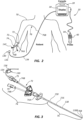
- FIGS. 1A-2 depict various components of a placement system (“system"), generally designated at 10, configured in accordance with one example embodiment of the present invention.
- the system 10 generally includes a console 20, display 30, probe 40, and optical module 50, each of which is described in further detail below.
- FIG. 2 shows the general relation of these components to a patient 70 during a procedure to place a catheter 72 into the patient vasculature through a skin insertion site 73.
- the catheter 72 generally includes a proximal portion 74 that generally remains exterior to the patient and a distal potion 76 that generally resides within the patient vasculature after placement is complete.
- the system 10 is employed to ultimately position a distal tip 76A of the catheter 72 in a desired position within the patient vasculature.
- the desired position for the catheter distal tip 76A is proximate the patient's heart, such as in the lower one-third (1/3 rd ) portion of the Superior Vena Cava ("SVC").
- the catheter proximal portion 74 further includes a bifurcation hub 74A that provides fluid communication between the one or more lumens of the catheter 72 and one or more extension legs 74B extending proximally from the bifurcation hub.
- the bifurcation hub can include one, two, or more fluid paths to fluidly connect the catheter lumens with the corresponding extension legs 74B.
- FIG. 2 An example implementation of the console 20 is shown in FIG. 2 , though it is appreciated that the console can take one of a variety of forms.
- FIG. 1A shows that a processor 22, including non-volatile memory such as EEPROM for instance, is included in the console 20 for controlling system function during operation of the system 10, thus acting as a control processor.
- a digital controller/analog interface 24 is also included with the console 20 and is in communication with both the processor 22 and other system components to govern interfacing between the probe 40, optical module 50, and other system components.
- the system 10 further includes ports 52 for connection with the optical module 50 and optional components 54 including a printer, storage media, keyboard, etc.
- the ports in one embodiment are USB ports, though other port types or a combination of port types can be used for this and the other interfaces connections described herein.
- a power connection 56 is included with the console 20 to enable operable connection to an external power supply 58.
- An internal battery 60 can also be employed, either with or exclusive of an external power supply.
- Power management circuitry 59 is included with the digital controller/analog interface 24 of the console to regulate power use and distribution.
- the display 30 in the present embodiment is integrated into the console 20 and is employed as a user interface to display information to the clinician during the catheter placement procedure.
- the display may be separate from the console.
- the content depicted by the display 30 changes according to which mode the catheter placement system is in: optical, US, or other modality.
- a console button interface 32 and buttons included on the probe 40 can be used to immediately call up a desired mode to the display 30 by the clinician to assist in the placement procedure.
- information from multiple modes, such as optical and US may be displayed simultaneously.
- the single display 30 of the system console 20 can be employed for ultrasound guidance in accessing a patient's vasculature and optical modality-based guidance during catheter advancement through the vasculature.
- the display 30 is an LCD device.
- the probe 40 is employed in connection with the first modality mentioned above, i.e., ultrasound ("US")-based visualization of a vessel, such as a vein, in preparation for insertion of the catheter 72 into the vasculature.
- US ultrasound
- Such visualization gives real time ultrasound guidance for introducing the catheter into the vasculature of the patient and assists in reducing complications typically associated with such introduction, including inadvertent arterial puncture, hematoma, pneumothorax, etc.
- the handheld probe 40 includes a head that houses a piezoelectric array for producing ultrasonic pulses and for receiving echoes thereof after reflection by the patient's body when the head is placed against the patient's skin proximate the prospective insertion site 73 ( FIG. 2 ).
- the probe 40 further includes a plurality of control buttons, which can be included on a button pad.
- the modality of the system 10 can be controlled by the control buttons, thus eliminating the need for the clinician to reach out of the sterile field, which is established about the patient insertion site prior to catheter placement, to change modes via use of the console button interface 32.
- a clinician employs the first (US) modality to determine a suitable insertion site and establish vascular access, such as with a needle or introducer, then with the catheter.
- the clinician can then seamlessly switch, via button pushes on the probe button pad 82, to the optical modality without having to reach out of the sterile field.
- the optical modality can be used to assist in advancement of the catheter 72 through the vasculature toward an intended destination.
- FIG. 1 shows that the probe 40 further includes button and memory controller 42 for governing button and probe operation.
- the button and memory controller 42 can include non-volatile memory, such as EEPROM, in one embodiment.
- the button and memory controller 42 is in operable communication with a probe interface 44 of the console 20, which includes a piezo input/output component 44A for interfacing with the probe piezoelectric array and a button and memory input/output component 44B for interfacing with the button and memory controller 42.
- the handheld ultrasound probe 40 is employed to enable US visualization of the peripheral vasculature of a patient in preparation for transcutaneous introduction of the catheter.
- the probe is also employed to control functionality of other modalities of the system 10, including the optical modality, when navigating the catheter toward its desired destination within the vasculature as described below.
- this feature enables functionality of any one of the modalities to be controlled entirely from within the sterile field.
- the probe 40 is a multi-purpose device, enabling convenient control of both US and other modality functionality of the system 10 from the sterile field. Note that additional or fewer components can be included with the system 10 than what is shown and described herein.
- the system 10 includes the optical module 50, which is shown in further detail ion FIG. 1B .
- the optical module 50 includes an optical transmitter, such as a laser 80, configured to produce outgoing optical signals incident on a plurality of optical fiber-based strain sensors (described further below) of the catheter assembly.
- the optical module 50 as well as an optical receiver, such as a photodetector 82, configured to receive return optical signals from the optical fiber-based strain sensors of the catheter assembly.
- the laser 80 is a tunable swept laser and both the laser 80 and the photodetector 82 are operably connected to the processor 22 of the system 10 ( FIG. 1A ), which governs their operation.
- another suitable light source can also be employed in addition to a laser, including semi-coherent light sources, LED light sources, etc.
- FIG. 1A also shows that the optical module in the present embodiment is operably connected to a stylet 130, which includes an optical fiber and the plurality of strain sensors, as will be described further below.
- the stylet 130 is configured to be removably received within the catheter 72 during the procedure to place the catheter into the vasculature of the patient and enable the system 10 to guide the catheter distal tip 76B to a desired destination within the body.
- the optical fiber and strain sensors can be configured in other ways other than a stylet, some of which are discussed further below.
- the optical module 50 can include other components and be included within the system 10 in other configurations apart from what is shown and described herein.
- FIG. 2 shows the stylet 130 in place within the catheter 72 as the catheter is being inserted into the patient 70 with the assistance of the system 10.
- FIGS. 2 and 3 depict further details regarding the stylet 130 and the catheter 72.
- the catheter 72 includes an elongate catheter tube 150 defining one or more lumens 216 extending between proximal and distal ends of the catheter tube, which are in communication with the corresponding extension legs 74B via the bifurcation hub 74A, as described further above.
- the catheter 72 includes two lumens 216 and two corresponding extension legs 74B, though other numbers of lumens and extension legs are possible. Luer connectors 75 are included on the proximal ends of the extension legs 74B.
- the stylet 130 is an elongate device and includes a system connector 132 on its proximal end 130A to enable the stylet to operably connect with the console 20 ( FIG. 2 ) or other suitable component of the system 10 via a threading (or other suitable) engagement.
- a tether 134 distally extends between the system connector 132 to a catheter connector 142 configured to threadably engage (or otherwise connect with) the luer connector 75 of one of the extension legs 74B of the catheter 72, as seen in FIG. 3 .
- a fiber-bearing portion 138 of the stylet 130 extends distally from the catheter connector 142 to a distal end 130B of the stylet.
- a handle 136 is included with the tether 134 to assist with manipulation of the stylet 130 by the user during system operation.
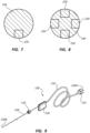
- the fiber-bearing portion 138 includes, as seen in FIG. 6 , an elongate core wire 138A with an optical fiber 140 disposed in a longitudinal notch defined along an outer surface thereof. So configured, the core wire 138A and optical fiber 140 extend distally from the catheter connector 142 to the distal end of the stylet 130 ( FIG. 9 ). The optical fiber 140 is secured within the notch of the core wire 138A by potting 214 (such as an adhesive), or by other suitable mode.
- the core wire 138A includes a suitable, flexible material, including stainless steel for instance.
- FIG. 6 shows the fiber-bearing portion 138 disposed in a lumen 216 defined by a wall 210 of a single-lumen catheter tube 150, though it is appreciated that the size, shape, and other configuration of the fiber-bearing portion 138 can vary from what is shown and described herein in order to accommodate catheters, lumens, and medical devices of differing configurations.
- the stylet 130 is inserted into the catheter 72 during use of the system 10 to place the catheter 72 in the body of the patient 70.
- the stylet 130 is shown with the fiber-bearing portion 138 disposed in the lumen of the catheter 72 and the tether 134 extending from the fiber-bearing portion to the console 20 such that the stylet is operably connected to the system 10 (via the stylet system connector 132).
- outgoing optical signals produced by the laser 80 ( FIG. 1B ) of the optical module 50 and return optical signals to be received by the photodetector 82 can travel to and from the optical fiber 140 ( FIG. 6 ) and its corresponding strain sensors, as will be discussed further below.
- FIG. 3 depicts the manner of operable connection of the stylet with the catheter 72.
- the fiber-bearing portion 138 is disposed within one of the lumens 216 of the catheter tube 150 such that the distal end of the stylet 130B - and the distal end of the fiber-bearing portion and accompanying optical fiber 140 - is substantially co-terminal with the distal tip 76B of the catheter.
- the fiber-bearing portion 138 extends proximally up the lumen 216, through the bifurcation hub 74A and corresponding extension leg 74Bto the catheter connector 142, which is shown threadably attached to the luer connector 75 of the extension leg.
- the tether 134 is further shown extending from the catheter 72 to operably connect with the console 20, as shown in FIG. 2 .
- This connective configuration is used during the procedure to insert the catheter 72 into the body of the patient 70, and in one embodiment the stylet is pre-loaded into the catheter during time of catheter manufacture or prior to commencement of the insertion procedure.
- the stylet 130, the fiber-bearing portion 138, and the optical fiber 140 can be configured in other ways while still enabling the desired functionality of the system 10 to be performed.
- the optical fiber 140 need not be substantially co-terminal with the distal tip 76B of the catheter 72, but can terminate proximal or distal thereto, as may be appreciated by one skilled in the art.
- the strain sensors of the optical fiber 140 included with the fiber-bearing portion 138 of the stylet 130 enable the catheter 72 to be tracked during its advancement through the patient vasculature.
- a guidewire or other catheter guiding apparatus could include the components and functionality described herein.
- stylet as used herein can include any one of a variety of devices configured for removable placement within a lumen of the catheter (or other portion of a medical device) to assist in placing a distal end of the catheter in a desired location within the patient's vasculature.
- connection schemes between the stylet 130 and the system 10/console 20 can also be used without limitation.
- a sterile drape is often positioned over the patient 70 during the catheter insertion procedure in order to define the majority of a sterile field: areas above the drape are sterile, while areas below (excluding the insertion site and immediately surrounding region) are non-sterile. For instance, areas and components above the drape and proximate to the insertion site 73 (including the catheter 72, the stylet 130, and tether 134) are included in the sterile field, while areas and components below the drape, including the patient's chest and regions immediately surrounding the patient 70 are considered a non-sterile field.
- connection nodes can be included with the stylet in order to pierce the drape while not compromising the sterile field.
- U.S. Patent No. 8,781 , 555 includes various examples of drape-piercing embodiments that can be employed to enable the stylet to acceptably pass through the drape while still enabling outgoing and return optical signals, as well as other signals, to pass between the optical fiber 140 and the console 20.
- FIG. 4 generally depicts a portion, or structure 100, of the catheter tube 150 of the catheter 72 to depict the spatial relationship between the catheter tube and the strain sensors included with the optical fiber 140 discussed above.
- the strain sensors 204 are positioned a distance c from a neutral axis of 206 of the catheter tube 150. When operative, the strain sensors 204 are capable of each detecting a corresponding strain ⁇ such that strain ⁇ 0 is detected at strain sensor 204 positioned at x 0 at the junction for section ⁇ 0 , etc.
- U.S. Patent No. 7, 715, 994 gives further details regarding the strain sensors and their spatial distribution as depicted in FIG. 4 .
- FIG. 7 shows that, in one embodiment, a predetermined sensor position region 220 is defined within the optical fiber 140, wherein the sensors 204 are disposed along the longitudinal length of the optical fiber.
- multiple sensor position regions 220 can be defined within the single optical fiber 140, as shown in FIG. 8 , for instance, such that distinct series, or channels, of strain or other sensors can be included on a single optical fiber.
- These multiple, non-colinear channels of strain sensors can be employed for differing purposes, such as one or more series to indicate medical device position with another series to monitor temperature along the medical device, for instance.
- the strain sensors 204 in one embodiment can be included with an optical fiber that is in turn included in a fiber-bearing of a stylet, such as the stylet 130 described above in connection with FIGS. 3 , 6 , and 9 .
- the strain sensors 204 are included with an optical fiber that is permanently incorporated into the catheter tube 150, such as is seen in FIG. 5 .
- Many other possible strain sensor implementations are possible, including other types of fiber optic sensors.
- the strain sensors 204 are configured as fiber Bragg grating ("FBG") sensors.
- the FBG sensors 34 are each configured to detect strain of the optical fiber at each sensor location, thus enabling the shape and movement of the optical fiber, and thus the catheter tube 150 with which it is included, to be detected and determined as the catheter is inserted into the body of the patient 70, as explained immediately below.
- the optical modality of the system 10 can be employed to advance the catheter distal tip 76A toward its intended destination proximate the SA node, in the current embodiment, noting that other intended destinations are also possible.
- the catheter 72 carries within one of its lumens 216 the stylet 130 including the fiber-bearing portion 138, which in turn includes the optical fiber 140 with its strain sensors 204 ( e . g ., the FBG sensors in the present embodiment).
- strain sensors 204 e . g ., the FBG sensors in the present embodiment.
- optical signals propagate distally through the optical fiber 140 via the stylet tether 134 to interrogate each of the FBG-type sensors 204, resulting in return optical signals from the sensors.
- the return optical signals from the FBG-type sensors 204 are received by the photodetector 82 of the optical module after travelling proximally through the optical fiber 140 and the stylet tether 134, which are then forwarded to the processor 22.
- the outgoing optical signal interrogation and return optical signal process is iterated at a scan rate to provide real-time monitoring. In one embodiment scan rates of 24 scans per second are employed, though other rates are possible. Specified algorithms and processes are followed to determine from the return optical signals the strain data from each of the FBG-type sensor 204.
- a method for placing a catheter assembly (or other medical device) into a body of a patient includes stages: propagating an outgoing optical signal to a plurality of optical fiber-based strain sensors included with the catheter assembly; receiving a return optical signal from the strain sensors; and processing the return optical signal received from the strain sensors to derive data relating to the medical device. These stages are successively repeated while inserting the catheter assembly into the body of the patient so as to guide the catheter assembly to its intended destination.
- strain data results in specified strain data to be correlated along the sensor-equipped length of the optical fiber 140.
- the strain data enables information regarding the two- and three-dimensional shape of the catheter tube 150 within the patient of the patient 70 to be ascertained, given that the detected strain-related displacement, bending, pressure, and torsion/twisting of the optical fiber 140 correlates to the catheter tube itself in which the optical fiber is disposed.
- This and other informational aspects relating to the data collected from the sensors 204 can be communicated to the user of the system 1, via the display 30 and/or other suitable user interface mode, to assist the user in knowing the location, orientation and shape of the catheter 72 within the patient vasculature, thus enabling the user to advance the catheter distally and position the distal tip 76B of the catheter in a desired location therein, in part by the fact that the distal end of the sensor-equipped optical fiber 140 is substantially co-terminal with the distal tip of the catheter within the vasculature, in the present embodiment.
- the process of sending and receiving outgoing and return optical signals, respectively, occurs iteratively during system operation such that position, orientation, and shape information relating to the catheter 72 is continuously received by the user via the system 10 during the catheter placement procedure.
- the catheter 72 may be secured in place and the stylet 130 removed from the catheter lumen.
- the stylet may include one of a variety of configurations in addition to what is explicitly described herein.
- the stylet can attach directly or indirectly to the console.
- the optical fiber of the stylet can be integrated into the catheter structure itself, thus eliminating the need for the stylet in bearing the optical fiber and included strain sensors.
- FIG. 5 gives one example of such an embodiment, wherein the catheter tube 150 includes first and second optical fibers 140A, 140B that are each affixed to an inner surface of the tube wall 210 that defines the lumen 216.
- a potting 214 such as an adhesive, is used to adhere the optical fibers 140A, 140B to the tube wall 210.
- One, two, or more optical fibers can be included in the catheter tube in this manner.
- the optical fiber can incorporated into the catheter wall itself, such as via a co-extrusion process, for instance.
- the console 20 includes the electronic components, such as the processor 22 ( FIG. 1 ), necessary to process the return optical signals received by the photodetector 82 via the stylet 130 or other suitable structure including the optical fiber 140 and sensors 204.
- this functionality can be included in another system component including, for example, the optical module 50.
- the position, orientation, shape, and other information regarding the catheter 72, as provided by the optical fiber-based sensors 204 and as described above is communicated to the user of the system 10 to assist with placing the distal tip 76B (or other portion of the catheter) at a desired location within the patient vasculature/body, such as the lower 1/3 rd of the superior vena cava.
- such information is depicted on the display 30, included on the console 20 as part of the system 10, though it can be configured in other ways as well, including as a separate component in one embodiment.
- the functionality of the display 30 can be controlled by control buttons 84 included on the handheld probe 40 ( FIGS.
- the probe 40 is employed to also control some or all functionality of the system 10.
- the button interface 32 or other input configurations can also be used to control system functionality.
- aural information such as beeps, tones, etc., can also be employed by the system to assist the clinician during catheter placement.
- the buttons included on the probe 40 and the console button interface 32 can be configured in a variety of ways, including the use of user input controls in addition to buttons, such as slide switches, toggle switches, electronic or touch-sensitive pads, etc.
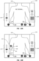
- FIG. 10A shows an example screenshot 318 as depicted on the display 30 while the system 10 is in operation.
- a representative body image 320 is shown.
- Other information is provided on the display screenshot 318, including a depth scale indicator 324, status/action indicia 326, and icons 328 corresponding to the button interface 32 included on the console 20 ( FIG. 1A ).
- the icons 328 in the present embodiment are simply indicators to guide the user in identifying the purpose of the corresponding buttons of the button interface 32, in another embodiment the display can be made touch-sensitive so that the icons themselves can function as button interfaces and can change according to the mode the system is in.
- the display screenshot may indicate "no signal," as seen in FIG. 10A , indicating that no data is being returned from the sensors 204 of the optical fiber 140.
- FIG. 10B a distal portion of the catheter 72 has been inserted into the body of the patient 70, which is represented in the screenshot 318 by a relatively short path of travel 330 distal to a depicted insertion site 332 (which corresponds to the actual insertion site 73 of FIG. 2 ) on the display 30.
- a still-external portion 334 of the catheter is also shown on the screenshot 318 of FIG. 10B , proximal to the depicted insertion site 332.
- Temperature-based differences as detected in data received from the return optical signals enables the system 10 to determine at which point along the length of the optical fiber 140 the catheter tube 150 has entered into the body 70 of the patient in the present embodiment, thus enabling the system to depict the location of the insertion site 332.
- the internal path of travel 330 and the external portion 334 can be depicted on the display.
- a position icon 314 is also depicted at the detected distal end of the sensor-equipped optical fiber 140, corresponding to the distal tip 76B of the catheter 72, in the present embodiment.
- the catheter 72 has advanced proximate a desired position within the patient vasculature, i.e., proximate the lower 1/3 rd portion of the SVC in the present embodiment, as indicated by the position icon 314 on the screenshot body image 320. This is indicated by the relatively longer internal path of travel 330 with respect to the insertion site 332.
- the system 10 is further able to detect and depict any bends or changes in direction in the catheter via processing of the return optical signals from the various sensors 204 along the length of optical fiber disposed in one of the lumens 216 of the catheter tube 150 ( FIG. 3 ).
- position, shape, and orientation of the catheter 72 is determined by the system 10 and communicated to the clinician via the display 30, thus enabling the clinician to accurately guide the catheter to the desired position within the vasculature.
- the mapping of the catheter as an image on the body image 320 to indicate the actual location of the catheter 72 within the actual body of the patient 70 is enabled by knowledge of the insertion site of the catheter (i.e. , a reference location) - here represented by the insertion site 332 of FIG. 10C , the length of the portion of the catheter found inside the patient body (represented by the internal portion of the catheter 330), and the shape/displacement of the catheter as detected by the optical fiber-based sensors 204 disposed within the catheter.
- FIG. 11 depicts a scenario where optical modality of the system 10 can assist a clinician in detecting a malposition scenario for the catheter 72 within the vasculature.
- the catheter tube 150 is disposed within a vessel 340 of the patient 70 in such a way as to undesirably double back on itself and form a kink region 342. Such kinks are possible during insertion of the catheter 72 into the body.
- the optical fiber 140 including the plurality of FBG-type sensors 204, is also shown running along the length of the lumen defined by the catheter tube 150. Return optical signals from the sensors 204 in the kink region 342 during system operation will indicate the strain in the optical fiber 140 caused by the kink.
- information relating to the kink can be communicated to the clinician via the display 30 or by other suitable means.
- the clinician can view the catheter tube doubling back on itself as depicted on the display. Once the kink condition has been identified, the clinician can correct the kink and proceed with catheter insertion.
- FIG. 11 further shows an obstruction 344, such as a thrombus or fibrin sheath, present proximate the distal end 76B of the catheter tube 150.
- an obstruction 344 such as a thrombus or fibrin sheath
- Such obstructions are also detectable by sensors 204 of the optical fiber 140 as part of the optical modality of the system 10. Once the obstruction condition has been communicated to the clinician, corrective measures may be undertaken to clear the obstruction from the catheter tube 150.
- optical fiber-based sensors can be employed to confirm that a previously inserted catheter assembly (or other medical device) is still positioned as desired within the body of the patient. In one embodiment, this is achieved by feeding a stylet including an optical fiber-based series of strain sensors distally within a lumen of the catheter until reaching the distal tip of the catheter. Strain and other measurements may then be performed by the sensors disposed within the catheter lumen, thus enabling the system with which the sensors are operably connected to determine the shape, orientation, and position of the catheter tube within the vasculature of the patient, including the termination point of the catheter distal tip. This enables a clinician to ensure the catheter is still positioned at the desired location.
- the optical modality described herein can detect and communicate other information to the clinician via the system 10 using the data provided by the sensor interrogation by the outgoing optical signals and the resultant return optical signals.
- information includes temperature, pressure, stiffness, strength, operational load on the catheter tube, liquid level within the lumen 14, blood oxygen level, magnetic field presence, etc.
- other conditions relating to the catheter including malposition/misdirection during catheter advancement including contralateral and IJ placement, arterial vs. venous placement, venous pressure and core body temperature, confirmation of the catheter staying within the true lumen of the vein or other vessel in the case of navigation through chronic total occlusion or other vessel blockage scenarios, etc.
Landscapes
- Health & Medical Sciences (AREA)
- Life Sciences & Earth Sciences (AREA)
- Engineering & Computer Science (AREA)
- Physics & Mathematics (AREA)
- General Health & Medical Sciences (AREA)
- Biomedical Technology (AREA)
- Heart & Thoracic Surgery (AREA)
- Animal Behavior & Ethology (AREA)
- Public Health (AREA)
- Veterinary Medicine (AREA)
- Surgery (AREA)
- Biophysics (AREA)
- Medical Informatics (AREA)
- Molecular Biology (AREA)
- Pathology (AREA)
- General Physics & Mathematics (AREA)
- Nuclear Medicine, Radiotherapy & Molecular Imaging (AREA)
- Radiology & Medical Imaging (AREA)
- Pulmonology (AREA)
- Anesthesiology (AREA)
- Hematology (AREA)
- Gynecology & Obstetrics (AREA)
- Human Computer Interaction (AREA)
- Robotics (AREA)
- Media Introduction/Drainage Providing Device (AREA)
- Endoscopes (AREA)
Claims (8)
- Système de mise en place (10) de dispositif médical pour insérer un dispositif médical allongé incluant un cathéter (72) dans un corps d'un patient (70) à travers un site d'insertion cutanée (73), comprenant :une pluralité de capteurs de contrainte (204) à base de fibre optique configurés pour être inclus avec le dispositif médical ;une source de lumière (80) configurée pour être fonctionnellement reliée à la pluralité de capteurs de contrainte (204) et produire des signaux optiques sortants incidents sur les capteurs de contrainte (204) ;un photodétecteur (82) configuré pour être fonctionnellement relié à la pluralité de capteurs de contrainte (204) et recevoir des signaux optiques de retour provenant des capteurs de contrainte (204) ;un processeur (22) configuré pour traiter des données issues des signaux optiques de retour, les données se rapportant à un aspect du dispositif médical ; etune interface utilisateur configurée pour communiquer des informations se rapportant à l'aspect du dispositif médical,dans lequel le cathéter (72) inclut une partie proximale (74) qui est configurée pour rester à l'extérieur du patient (70), une partie distale (76) qui est configurée pour résider dans le patient (70) une fois que la mise en place est achevée, et un tube (150) de cathéter allongé définissant une ou plusieurs lumières (216) s'étendant entre les extrémités proximale et distale du tube (150) de cathéter allongé,dans lequel la partie proximale (74) inclut un raccord de bifurcation (74A) qui assure une communication fluidique entre les une ou plusieurs lumières (216) du cathéter (72) et une ou plusieurs pattes d'extension (74B) s'étendant de manière proximale depuis le raccord de bifurcation (74A),dans lequel les une ou plusieurs lumières (216) sont en communication avec les pattes d'extension (74B) correspondantes via le raccord de bifurcation (74A),dans lequel les capteurs de contrainte (204) sont répartis le long d'une longueur longitudinale d'une fibre optique (140),dans lequel la fibre optique (140) est incorporée de manière permanente dans le tube (150) de cathéter,dans lequel l'interface utilisateur inclut un afficheur (30),dans lequel le processeur (22) est configuré pour amener l'afficheur (30) à inclure des informations se rapportant à une position du dispositif médical dans le corps du patient (70), dans lequel les informations incluent une image corporelle représentative (320), etdans lequel le processeur (22) est configuré pour amener l'afficheur (30) à mapper le cathéter (72) en tant qu'image sur l'image corporelle (320) pour indiquer un emplacement réel du cathéter (72) dans le corps du patient (70) permis par connaissance du site d'insertion (73) du cathéter (72), une longueur de la partie distale (76) et une forme/un déplacement du cathéter (72) tels que détectés par les capteurs de contrainte (204).
- Système selon la revendication 1, dans lequel la source de lumière (80) est un laser et dans lequel le laser et le photodétecteur (82) sont inclus dans un module optique (50).
- Système selon la revendication 1 ou 2, dans lequel les capteurs de contrainte (204) incluent des capteurs à réseau de Bragg à fibre (34).
- Système selon l'une quelconque des revendications 1 à 3, dans lequel l'aspect du dispositif médical inclut au moins une parmi une forme bidimensionnelle et une forme tridimensionnelle d'une partie du cathéter (72).
- Système selon l'une quelconque des revendications 1 à 4, dans lequel le processeur (22) est configuré pour commander la fonctionnalité de la source de lumière (80) et du photodétecteur (82).
- Système selon l'une quelconque des revendications 1 à 5, dans lequel les informations se rapportant à l'aspect du dispositif médical sont configurées pour aider un utilisateur du système à guider le dispositif médical jusqu'à une position souhaitée dans le corps du patient (70).
- Système selon l'une quelconque des revendications 1 à 6, dans lequel la source de lumière (80) est configurée pour émettre de manière itérative des signaux optiques sortants et dans lequel le photodétecteur (82) est configuré pour recevoir de manière itérative les signaux optiques de retour.
- Système selon l'une quelconque des revendications 1 à 7, dans lequel une première pluralité de capteurs de contrainte (204) sont inclus sur une première partie longitudinale d'une fibre optique (140), et dans lequel une seconde pluralité de capteurs de contrainte (204) sont inclus sur une seconde partie longitudinale de la fibre optique (140), les première et seconde pluralités de capteurs de contrainte (204) n'étant pas colinéaires entre eux sur la fibre optique (140).
Applications Claiming Priority (2)
| Application Number | Priority Date | Filing Date | Title |
|---|---|---|---|
| US201762483195P | 2017-04-07 | 2017-04-07 | |
| PCT/US2018/026493 WO2018187708A1 (fr) | 2017-04-07 | 2018-04-06 | Système de suivi et de surveillance de dispositif médical à base de fibre optique |
Publications (4)
| Publication Number | Publication Date |
|---|---|
| EP3606592A1 EP3606592A1 (fr) | 2020-02-12 |
| EP3606592A4 EP3606592A4 (fr) | 2020-12-23 |
| EP3606592C0 EP3606592C0 (fr) | 2025-01-08 |
| EP3606592B1 true EP3606592B1 (fr) | 2025-01-08 |
Family
ID=63710659
Family Applications (1)
| Application Number | Title | Priority Date | Filing Date |
|---|---|---|---|
| EP18781915.6A Active EP3606592B1 (fr) | 2017-04-07 | 2018-04-06 | Système de suivi et de surveillance de dispositif médical à base de fibre optique |
Country Status (4)
| Country | Link |
|---|---|
| US (2) | US12140487B2 (fr) |
| EP (1) | EP3606592B1 (fr) |
| CN (1) | CN211884909U (fr) |
| WO (1) | WO2018187708A1 (fr) |
Families Citing this family (60)
| Publication number | Priority date | Publication date | Assignee | Title |
|---|---|---|---|---|
| ITUB20155218A1 (it) * | 2015-10-16 | 2017-04-16 | Alberto Micco | Sistema per guidare dispositivi medici |
| US12140487B2 (en) | 2017-04-07 | 2024-11-12 | Bard Access Systems, Inc. | Optical fiber-based medical device tracking and monitoring system |
| US10992078B2 (en) | 2018-01-29 | 2021-04-27 | Bard Access Systems, Inc. | Connection system for establishing an electrical connection through a drape and methods thereof |
| WO2019221926A1 (fr) | 2018-05-18 | 2019-11-21 | Bard Access Systems, Inc. | Systèmes de connexion et procédés associés pour établir une connexion électrique à travers un champ |
| EP3997497B1 (fr) | 2019-07-29 | 2025-08-27 | Bard Access Systems, Inc. | Systèmes de connexion et procédés pour établir des connexions optiques et électriques à travers un champ |
| US12029498B2 (en) | 2019-08-08 | 2024-07-09 | Bard Access Systems, Inc. | Optical-fiber connector modules including shape-sensing systems and methods thereof |
| JP7524305B2 (ja) * | 2019-08-12 | 2024-07-29 | バード・アクセス・システムズ,インコーポレーテッド | 医療機器用の形状センシングシステム |
| CA3152545A1 (fr) | 2019-09-20 | 2021-03-25 | Bard Access Systems, Inc. | Outils et procedes de detection automatique de vaisseaux sanguins |
| WO2021108697A1 (fr) | 2019-11-25 | 2021-06-03 | Bard Access Systems, Inc. | Systèmes de suivi de pointe optique et leurs procédés |
| EP4061272B1 (fr) | 2019-11-25 | 2026-01-07 | Bard Access Systems, Inc. | Systèmes de détection de forme comprenant des filtres et procédés associés |
| CN215340440U (zh) | 2020-02-28 | 2021-12-28 | 巴德阿克塞斯系统股份有限公司 | 电学和光学连接系统及光学连接系统 |
| WO2021174117A1 (fr) | 2020-02-28 | 2021-09-02 | Bard Access Systems, Inc. | Cathéter à capacités de détection de forme optique |
| US12232818B2 (en) | 2020-03-03 | 2025-02-25 | Bard Access Systems, Inc. | System and method for optic shape sensing and electrical signal conduction |
| WO2021188826A1 (fr) * | 2020-03-19 | 2021-09-23 | Bard Access Systems, Inc. | Système et procédé de commande de fonctionnalité de multiples dispositifs médicaux |
| CN113456054B (zh) * | 2020-03-30 | 2025-08-12 | 巴德阿克塞斯系统股份有限公司 | 光学和电气诊断系统及其方法 |
| EP4161412A1 (fr) * | 2020-06-05 | 2023-04-12 | Koninklijke Philips N.V. | Système de guidage d'instrument d'intervention vers une cible interne |
| WO2021263023A1 (fr) | 2020-06-26 | 2021-12-30 | Bard Access Systems, Inc. | Système de détection de mauvais positionnement |
| WO2022005870A1 (fr) | 2020-06-29 | 2022-01-06 | Bard Access Systems, Inc. | Référence de cadre tridimensionnel automatique pour fibre optique |
| US11624677B2 (en) * | 2020-07-10 | 2023-04-11 | Bard Access Systems, Inc. | Continuous fiber optic functionality monitoring and self-diagnostic reporting system |
| CN114052658B (zh) | 2020-08-03 | 2025-12-16 | 巴德阿克塞斯系统股份有限公司 | 布拉格光栅光纤波动感测与监测系统 |
| WO2022055887A1 (fr) | 2020-09-08 | 2022-03-17 | Bard Access Systems, Inc. | Systèmes d'imagerie par ultrasons à ajustement dynamique et procédés associés |
| CN216257185U (zh) | 2020-09-10 | 2022-04-12 | 巴德阿克塞斯系统股份有限公司 | 超声探测器和超声系统 |
| EP4216819A1 (fr) | 2020-09-25 | 2023-08-02 | Bard Access Systems, Inc. | Système d'oxymétrie à fibres optiques pour la détection et la confirmation |
| EP4229456A1 (fr) | 2020-10-13 | 2023-08-23 | Bard Access Systems, Inc. | Couvercles de désinfection pour connecteurs fonctionnels de dispositifs médicaux et procédés associés |
| WO2022081723A1 (fr) | 2020-10-13 | 2022-04-21 | Bard Access Systems, Inc. | Dispositifs médicaux déployables activés par fibre optique pour le suivi, l'évaluation et la capture d'informations de déploiement |
| WO2022093991A1 (fr) | 2020-10-28 | 2022-05-05 | Bard Access Systems, Inc. | Systèmes et procédés comprenant des connecteurs de rupture de barrière procédurale et des dispositifs d'établissement de connexion |
| CN216558785U (zh) * | 2020-11-18 | 2022-05-17 | 巴德阿克塞斯系统股份有限公司 | 光纤管心针保持器 |
| EP4247267A1 (fr) | 2020-11-24 | 2023-09-27 | Bard Access Systems, Inc. | Système à ultrasons avec connaissance de cible et d'instrument médical |
| EP4247247B1 (fr) * | 2020-11-24 | 2025-12-24 | Bard Access Systems, Inc. | Instrument médical allongé activé par détection de forme de fibre optique orientable |
| US12165315B2 (en) | 2020-12-01 | 2024-12-10 | Bard Access Systems, Inc. | Ultrasound system with pressure and flow determination capability |
| WO2022119853A1 (fr) | 2020-12-01 | 2022-06-09 | Bard Access Systems, Inc. | Sonde ultrasonore à capacité de suivi de cible |
| EP4271279A1 (fr) * | 2021-01-06 | 2023-11-08 | Bard Access Systems, Inc. | Guidage d'aiguille par détection de forme par fibre optique |
| EP4280995A1 (fr) * | 2021-01-26 | 2023-11-29 | Bard Access Systems, Inc. | Système de détection de forme de fibre optique associé à un placement de port |
| CN217960146U (zh) | 2021-04-15 | 2022-12-06 | 巴德阿克塞斯系统股份有限公司 | 超声成像系统 |
| CN115363565A (zh) * | 2021-05-18 | 2022-11-22 | 巴德阿克塞斯系统股份有限公司 | 用于检测医疗设备在患者身体内的放置的医疗设备系统和方法 |
| EP4401659A1 (fr) | 2021-09-16 | 2024-07-24 | Bard Access Systems, Inc. | Interface de connexion de fibre à cycle d'accouplement élevé pouvant être remplacée |
| US20230097431A1 (en) * | 2021-09-27 | 2023-03-30 | Bard Access Systems, Inc. | Medical Instrument Shape Filtering Systems and Methods |
| WO2023055810A1 (fr) * | 2021-09-30 | 2023-04-06 | Bard Access Systems, Inc. | Cadre de référence de détection de forme |
| CN116019552A (zh) * | 2021-10-25 | 2023-04-28 | 巴德阿克塞斯系统股份有限公司 | 用于医疗设备放置的参考平面 |
| EP4422507B1 (fr) | 2021-11-03 | 2026-04-15 | Bard Access Systems, Inc. | Fonctionnalité optimisée par interopération de différenciation de vaisseau à base d'image et doppler |
| US12514532B2 (en) | 2022-03-01 | 2026-01-06 | Bard Access Systems, Inc. | Ultrasound imaging system |
| US12514533B2 (en) | 2022-03-01 | 2026-01-06 | Bard Access Systems, Inc. | Ultrasound imaging system |
| US12318149B2 (en) | 2022-03-08 | 2025-06-03 | Bard Access Systems, Inc. | Medical shape sensing devices and systems |
| CN116763338A (zh) | 2022-03-16 | 2023-09-19 | 巴德阿克塞斯系统股份有限公司 | 超声成像系统 |
| US12426956B2 (en) | 2022-03-16 | 2025-09-30 | Bard Access Systems, Inc. | Medical system and method for monitoring medical device insertion and illumination patterns |
| US12089815B2 (en) * | 2022-03-17 | 2024-09-17 | Bard Access Systems, Inc. | Fiber optic medical systems and devices with atraumatic tip |
| US12605116B2 (en) | 2022-04-11 | 2026-04-21 | Bard Access Systems, Inc. | Fiber optic medical systems and devices with electrical tip |
| US20230346482A1 (en) | 2022-04-27 | 2023-11-02 | Bard Access Systems, Inc. | Conductor Incorporated Fiber Enabled Medical Systems |
| US20230346314A1 (en) | 2022-04-27 | 2023-11-02 | Bard Access Systems, Inc. | Steerable Devices for Fiber Enabled Medical Systems |
| CN115025367A (zh) * | 2022-04-29 | 2022-09-09 | 南京航空航天大学 | 基于ipmc的自适应微导管导向装置 |
| US12575893B2 (en) | 2022-06-24 | 2026-03-17 | Bard Access Systems, Inc. | Shape sensing fiber optic tip protection systems and devices |
| US12343117B2 (en) | 2022-06-28 | 2025-07-01 | Bard Access Systems, Inc. | Fiber optic medical systems and methods for identifying blood vessels |
| US12349984B2 (en) * | 2022-06-29 | 2025-07-08 | Bard Access Systems, Inc. | System, method, and apparatus for improved confirm of an anatomical position of a medical instrument |
| US12564340B2 (en) * | 2022-07-12 | 2026-03-03 | Bard Access Systems, Inc. | Eccentric single-core fiber-optic enabled medical device |
| US20240065673A1 (en) * | 2022-08-24 | 2024-02-29 | Bard Access Systems, Inc. | Ultrasound Smart Port Accessory |
| CN221154105U (zh) | 2022-09-23 | 2024-06-18 | 巴德阿克塞斯系统股份有限公司 | 用于在置于患者体内之前确定在插入部位与目标定位之间延伸所需的导管长度的系统 |
| CN115607807A (zh) * | 2022-10-11 | 2023-01-17 | 深圳市爱博医疗机器人有限公司 | 细长医疗器械 |
| US20240226504A1 (en) * | 2023-01-10 | 2024-07-11 | Bard Access Systems, Inc. | Adjustable Elongate Medical Device Handle |
| CA3238285A1 (en) | 2023-05-15 | 2025-07-07 | Northern Digital Inc. | Fiber optic shape sensing mangement |
| WO2025166005A1 (fr) * | 2024-02-02 | 2025-08-07 | Arizona Board Of Regents On Behalf Of Arizona State University | Appareil et procédé de détermination d'informations de position d'un ensemble orientable intra-corps |
Family Cites Families (251)
| Publication number | Priority date | Publication date | Assignee | Title |
|---|---|---|---|---|
| IL78756A0 (en) | 1986-05-12 | 1986-08-31 | Biodan Medical Systems Ltd | Catheter and probe |
| EP0471764B1 (fr) | 1989-05-03 | 1996-07-03 | ENTERPRISE MEDICAL TECHNOLOGIES, Inc. | Instrument de traitement de la stenose par voie intraluminale |
| CN1049287A (zh) | 1989-05-24 | 1991-02-20 | 住友电气工业株式会社 | 治疗导管 |
| US5163935A (en) | 1991-02-20 | 1992-11-17 | Reliant Laser Corporation | Surgical laser endoscopic focusing guide with an optical fiber link |
| EP0573535B1 (fr) | 1991-02-26 | 2000-12-27 | Massachusetts Institute Of Technology | Systemes et procedes de spectroscopie moleculaire, permettant d'etablir le diagnostic des tissus |
| EP0619748B1 (fr) | 1991-08-28 | 1995-11-08 | Medtronic, Inc. | Stylet orientable et manche de manipulation |
| US5211165A (en) | 1991-09-03 | 1993-05-18 | General Electric Company | Tracking system to follow the position and orientation of a device with radiofrequency field gradients |
| US5275151A (en) | 1991-12-11 | 1994-01-04 | Clarus Medical Systems, Inc. | Handle for deflectable catheter |
| US5280786A (en) | 1992-01-21 | 1994-01-25 | Fiberoptic Sensor Technologies, Inc. | Fiberoptic blood pressure and oxygenation sensor |
| US5423321A (en) | 1993-02-11 | 1995-06-13 | Fontenot; Mark G. | Detection of anatomic passages using infrared emitting catheter |
| AU6666894A (en) | 1993-04-22 | 1994-11-08 | Pixsys, Inc. | System for locating relative positions of objects |
| US5454807A (en) | 1993-05-14 | 1995-10-03 | Boston Scientific Corporation | Medical treatment of deeply seated tissue using optical radiation |
| US5517997A (en) | 1994-09-15 | 1996-05-21 | Gabriel Medical, Inc. | Transillumination of body members for protection during body invasive procedures |
| US6597941B2 (en) | 1994-09-15 | 2003-07-22 | Stryker Corporation | Transillumination of body members for protection during body invasive procedures |
| US5740808A (en) | 1996-10-28 | 1998-04-21 | Ep Technologies, Inc | Systems and methods for guilding diagnostic or therapeutic devices in interior tissue regions |
| US5879306A (en) | 1996-06-13 | 1999-03-09 | Stryker Corporation | Infrared system for visualizing body members |
| US5904147A (en) | 1996-08-16 | 1999-05-18 | University Of Massachusetts | Intravascular catheter and method of controlling hemorrhage during minimally invasive surgery |
| US7603166B2 (en) | 1996-09-20 | 2009-10-13 | Board Of Regents University Of Texas System | Method and apparatus for detection of vulnerable atherosclerotic plaque |
| US6119031A (en) | 1996-11-21 | 2000-09-12 | Boston Scientific Corporation | Miniature spectrometer |
| US5872879A (en) | 1996-11-25 | 1999-02-16 | Boston Scientific Corporation | Rotatable connecting optical fibers |
| US6069698A (en) | 1997-08-28 | 2000-05-30 | Olympus Optical Co., Ltd. | Optical imaging apparatus which radiates a low coherence light beam onto a test object, receives optical information from light scattered by the object, and constructs therefrom a cross-sectional image of the object |
| US6175752B1 (en) | 1998-04-30 | 2001-01-16 | Therasense, Inc. | Analyte monitoring device and methods of use |
| US6081741A (en) | 1998-06-05 | 2000-06-27 | Vector Medical, Inc. | Infrared surgical site locating device and method |
| CA2334978A1 (fr) | 1998-06-09 | 1999-12-16 | Steve Baker | Catheter cardio-vasculaire et procede de mise en place de catheter a l'aide de la transillumination de tissus |
| AU4644799A (en) | 1998-08-02 | 2000-03-14 | Super Dimension Ltd. | Intrabody navigation system for medical applications |
| US6319227B1 (en) | 1998-08-05 | 2001-11-20 | Scimed Life Systems, Inc. | Automatic/manual longitudinal position translator and rotary drive system for catheters |
| AU6417599A (en) | 1998-10-08 | 2000-04-26 | University Of Kentucky Research Foundation, The | Methods and apparatus for (in vivo) identification and characterization of vulnerable atherosclerotic plaques |
| US6178346B1 (en) | 1998-10-23 | 2001-01-23 | David C. Amundson | Infrared endoscopic imaging in a liquid with suspended particles: method and apparatus |
| US6615072B1 (en) | 1999-02-04 | 2003-09-02 | Olympus Optical Co., Ltd. | Optical imaging device |
| US6398721B1 (en) | 1999-02-19 | 2002-06-04 | Olympus Optical Co., Ltd. | Surgical microscope apparatus |
| US6208887B1 (en) | 1999-06-24 | 2001-03-27 | Richard H. Clarke | Catheter-delivered low resolution Raman scattering analyzing system for detecting lesions |
| US7935108B2 (en) | 1999-07-14 | 2011-05-03 | Cardiofocus, Inc. | Deflectable sheath catheters |
| US6485482B1 (en) | 1999-07-30 | 2002-11-26 | Scimed Life Systems, Inc. | Rotational and translational drive coupling for catheter assembly |
| US6299622B1 (en) | 1999-08-19 | 2001-10-09 | Fox Hollow Technologies, Inc. | Atherectomy catheter with aligned imager |
| US6687010B1 (en) | 1999-09-09 | 2004-02-03 | Olympus Corporation | Rapid depth scanning optical imaging device |
| US7366562B2 (en) | 2003-10-17 | 2008-04-29 | Medtronic Navigation, Inc. | Method and apparatus for surgical navigation |
| GB2371361A (en) | 1999-10-29 | 2002-07-24 | Advanced Sensor Technology Llc | Optical fiber navigation system |
| US6685666B1 (en) | 1999-11-12 | 2004-02-03 | Mark G. Fontenot | Catheters for breast surgery |
| US6692430B2 (en) | 2000-04-10 | 2004-02-17 | C2Cure Inc. | Intra vascular imaging apparatus |
| US6650923B1 (en) | 2000-04-13 | 2003-11-18 | Ev3 Sunnyvale, Inc. | Method for accessing the left atrium of the heart by locating the fossa ovalis |
| DE60141090D1 (de) | 2000-10-30 | 2010-03-04 | Gen Hospital Corp | Optische systeme zur gewebeanalyse |
| US20020115922A1 (en) | 2001-02-12 | 2002-08-22 | Milton Waner | Infrared assisted monitoring of a catheter |
| EP2333521B1 (fr) | 2001-04-30 | 2019-12-04 | The General Hospital Corporation | Procédé et appareil permettant d'améliorer la clarté et la sensibilité de l'image en tomographie à cohérence optique au moyen d'une interaction permettant de contrôler les propriétés focales et la synchronisation de cohérence |
| US7532920B1 (en) | 2001-05-31 | 2009-05-12 | Advanced Cardiovascular Systems, Inc. | Guidewire with optical fiber |
| US6701181B2 (en) | 2001-05-31 | 2004-03-02 | Infraredx, Inc. | Multi-path optical catheter |
| US7992573B2 (en) * | 2001-06-19 | 2011-08-09 | The Trustees Of The University Of Pennsylvania | Optically guided system for precise placement of a medical catheter in a patient |
| WO2002103409A2 (fr) | 2001-06-19 | 2002-12-27 | The Trustees Of The University Of Pennsylvania | Systeme de guidage optique pour placement de catheter invasif |
| AU2002327779B2 (en) | 2001-09-28 | 2008-06-26 | Angiodynamics, Inc. | Impedance controlled tissue ablation apparatus and method |
| US6895267B2 (en) | 2001-10-24 | 2005-05-17 | Scimed Life Systems, Inc. | Systems and methods for guiding and locating functional elements on medical devices positioned in a body |
| US20030092995A1 (en) | 2001-11-13 | 2003-05-15 | Medtronic, Inc. | System and method of positioning implantable medical devices |
| US6711426B2 (en) | 2002-04-09 | 2004-03-23 | Spectros Corporation | Spectroscopy illuminator with improved delivery efficiency for high optical density and reduced thermal load |
| EP1551299A4 (fr) | 2002-08-05 | 2010-01-20 | Infraredx Inc | Analyse spectroscopique par proche infrarouge des parois de vaisseaux sanguins |
| EP1526888A2 (fr) | 2002-08-05 | 2005-05-04 | Miravant Medical Technologies | Catheter d'apport de lumiere |
| US6892090B2 (en) | 2002-08-19 | 2005-05-10 | Surgical Navigation Technologies, Inc. | Method and apparatus for virtual endoscopy |
| EP1539031B1 (fr) | 2002-09-19 | 2013-01-02 | Memory Metal Holland BV | Filtre vasculaire a resistance et a souplesse ameliorees |
| US7599730B2 (en) | 2002-11-19 | 2009-10-06 | Medtronic Navigation, Inc. | Navigation system for cardiac therapies |
| US7132645B2 (en) | 2003-03-07 | 2006-11-07 | Infraredx, Inc. | System and method for assessing catheter connection using return loss |
| CN100382750C (zh) | 2003-03-07 | 2008-04-23 | 皇家飞利浦电子股份有限公司 | 体内定位器械的装置和方法 |
| DE10313868B4 (de) | 2003-03-21 | 2009-11-19 | Siemens Ag | Katheter zur magnetischen Navigation |
| DE10323217A1 (de) | 2003-05-22 | 2004-12-16 | Siemens Ag | Optisches Kohärenztomographiesystem zur Untersuchung des menschlichen oder tierischen Gewebes oder von Organen |
| US7322953B2 (en) | 2003-08-04 | 2008-01-29 | Covidien Ag | Catheter device |
| US7840253B2 (en) | 2003-10-17 | 2010-11-23 | Medtronic Navigation, Inc. | Method and apparatus for surgical navigation |
| US8571640B2 (en) | 2003-12-11 | 2013-10-29 | The Regents Of The University Of California | Catheter based mid-infrared reflectance and reflectance generated absorption spectroscopy |
| DE10358735B4 (de) | 2003-12-15 | 2011-04-21 | Siemens Ag | Kathetereinrichtung umfassend einen Katheter, insbesondere einen intravaskulären Katheter |
| US7587236B2 (en) | 2004-01-08 | 2009-09-08 | Lawrence Livermore National Security, Llc | Optical spectroscopy for the detection of ischemic tissue injury |
| US20050261598A1 (en) | 2004-04-07 | 2005-11-24 | Triage Wireless, Inc. | Patch sensor system for measuring vital signs |
| US20050278010A1 (en) | 2004-05-27 | 2005-12-15 | Scimed Life Systems, Inc. | Stent delivery system with imaging capability |
| US20060013523A1 (en) | 2004-07-16 | 2006-01-19 | Luna Innovations Incorporated | Fiber optic position and shape sensing device and method relating thereto |
| US7772541B2 (en) | 2004-07-16 | 2010-08-10 | Luna Innnovations Incorporated | Fiber optic position and/or shape sensing based on rayleigh scatter |
| US20080039715A1 (en) | 2004-11-04 | 2008-02-14 | Wilson David F | Three-dimensional optical guidance for catheter placement |
| US11478152B2 (en) | 2005-02-02 | 2022-10-25 | Intuitive Surgical Operations, Inc. | Electrophysiology mapping and visualization system |
| US7918787B2 (en) | 2005-02-02 | 2011-04-05 | Voyage Medical, Inc. | Tissue visualization and manipulation systems |
| US20060189959A1 (en) * | 2005-02-22 | 2006-08-24 | Schneiter James A | High flow diffusion catheter |
| US8182433B2 (en) | 2005-03-04 | 2012-05-22 | Endosense Sa | Medical apparatus system having optical fiber load sensing capability |
| DE102005012699A1 (de) | 2005-03-18 | 2006-09-28 | Siemens Ag | Verfahren zur medizinischen Bildgebung sowie medizinisches bildgebendes System |
| EP3095379A1 (fr) | 2005-04-15 | 2016-11-23 | Surgisense Corporation | Instruments chirurgicaux avec des capteurs pour détecter les propriétés du tissu, et systèmes utilisant ces instruments |
| WO2006116701A2 (fr) | 2005-04-28 | 2006-11-02 | Research Foundation Of The City University Of New York | Systemes et procedes d'imagerie pour ameliorer l'imagerie de retrodiffusion a l'aide d'une memoire a polymerisation circulaire |
| US20090118612A1 (en) | 2005-05-06 | 2009-05-07 | Sorin Grunwald | Apparatus and Method for Vascular Access |
| EP1887940B1 (fr) | 2005-05-06 | 2013-06-26 | Vasonova, Inc. | Appareil permettant de guider et positionner un dispositif endovasculaire |
| EP1909853B1 (fr) | 2005-07-19 | 2015-03-18 | Biosensors International Group, Ltd. | Protocoles d'imagerie |
| US20070073160A1 (en) | 2005-09-13 | 2007-03-29 | Children's Medical Center Corporation | Light-guided transluminal catheter |
| US7930065B2 (en) * | 2005-12-30 | 2011-04-19 | Intuitive Surgical Operations, Inc. | Robotic surgery system including position sensors using fiber bragg gratings |
| US20070201793A1 (en) * | 2006-02-17 | 2007-08-30 | Charles Askins | Multi-core optical fiber and method of making and using same |
| CN102599875B (zh) | 2006-03-22 | 2015-03-11 | 皇家飞利浦电子股份有限公司 | 医疗器械系统 |
| US8187189B2 (en) | 2006-04-28 | 2012-05-29 | The Invention Science Fund I, Llc | Imaging via blood vessels |
| US9596994B2 (en) | 2006-06-02 | 2017-03-21 | J. William J. Futrell | System and methods for illuminating materials |
| US20080082004A1 (en) | 2006-09-08 | 2008-04-03 | Triage Wireless, Inc. | Blood pressure monitor |
| EP3610810B1 (fr) | 2006-11-21 | 2023-02-01 | Boston Scientific Scimed, Inc. | Dispositifs endovasculaires d'exploitation d'espace intramural |
| US7729735B1 (en) | 2006-11-30 | 2010-06-01 | Dartmouth-Hitchcock Clinic | System and method for venous oximetry using a catheter |
| US8073517B1 (en) | 2006-11-30 | 2011-12-06 | Dartmouth-Hitchcock Clinic | System and method for measuring blood constituents using a catheter |
| US20080172119A1 (en) | 2007-01-12 | 2008-07-17 | Medtronic Vascular, Inc. | Prosthesis Deployment Apparatus and Methods |
| US20080183128A1 (en) * | 2007-01-24 | 2008-07-31 | John Morriss | Methods, devices and systems for treatment and/or diagnosis of disorders of the ear, nose and throat |
| US8700358B1 (en) | 2007-03-07 | 2014-04-15 | The United States Of America As Represented By The Administrator Of The National Aeronautics And Space Administration | Method for reducing the refresh rate of Fiber Bragg Grating sensors |
| WO2008131303A2 (fr) | 2007-04-20 | 2008-10-30 | Hansen Medical, Inc. | Systèmes de détection de la forme d'une fibre optique |
| US8622935B1 (en) | 2007-05-25 | 2014-01-07 | Endosense Sa | Elongated surgical manipulator with body position and distal force sensing |
| US9622706B2 (en) | 2007-07-12 | 2017-04-18 | Volcano Corporation | Catheter for in vivo imaging |
| EP2628460B1 (fr) | 2007-08-14 | 2021-08-11 | Koninklijke Philips N.V. | Systèmes d'instruments robotisés utilisant des capteurs à fibres optiques |
| CN101925333B (zh) | 2007-11-26 | 2014-02-12 | C·R·巴德股份有限公司 | 用于脉管系统内的导管放置的集成系统 |
| US9521961B2 (en) * | 2007-11-26 | 2016-12-20 | C. R. Bard, Inc. | Systems and methods for guiding a medical instrument |
| US8781555B2 (en) * | 2007-11-26 | 2014-07-15 | C. R. Bard, Inc. | System for placement of a catheter including a signal-generating stylet |
| US9649048B2 (en) * | 2007-11-26 | 2017-05-16 | C. R. Bard, Inc. | Systems and methods for breaching a sterile field for intravascular placement of a catheter |
| US12440238B2 (en) | 2007-11-26 | 2025-10-14 | C. R. Bard, Inc. | Apparatus for use with needle insertion guidance system |
| US9211160B2 (en) | 2008-01-16 | 2015-12-15 | Luiz Geraldo Pivotto | Remotely controlled catheter insertion system with automatic control system |
| US11123047B2 (en) | 2008-01-28 | 2021-09-21 | The General Hospital Corporation | Hybrid systems and methods for multi-modal acquisition of intravascular imaging data and counteracting the effects of signal absorption in blood |
| JP5069585B2 (ja) | 2008-02-25 | 2012-11-07 | 富士フイルム株式会社 | 光プローブを用いた光断層画像化装置 |
| US9050131B2 (en) | 2008-06-18 | 2015-06-09 | Mako Surgical Corp. | Fiber optic tracking system and method for tracking a substantially rigid object |
| US20100030063A1 (en) | 2008-07-31 | 2010-02-04 | Medtronic, Inc. | System and method for tracking an instrument |
| WO2010023579A1 (fr) | 2008-08-28 | 2010-03-04 | Koninklijke Philips Electronics, N.V. | Dispositif, appareil et procédé permettant d’obtenir des signaux physiologiques par le biais d’un tube d’alimentation |
| US9315663B2 (en) | 2008-09-26 | 2016-04-19 | Mikro Systems, Inc. | Systems, devices, and/or methods for manufacturing castings |
| US20110245662A1 (en) | 2010-04-06 | 2011-10-06 | Eggers Philip E | Hemodynamic Detection of Circulatory Anomalies |
| EP2432542A4 (fr) | 2009-05-20 | 2013-07-03 | Cornova Inc | Systèmes et procédés pour l'analyse et le traitement d'une lumière corporelle |
| CN102625669B (zh) | 2009-06-08 | 2015-09-23 | 核磁共振成像介入技术有限公司 | 能够近实时地跟踪和生成柔性体内装置的动态可视化的mri导向的介入系统 |
| WO2010146588A2 (fr) | 2009-06-16 | 2010-12-23 | Technion- Research And Development Foundation Ltd. | Système miniature permettant de diagnostiquer une maladie |
| WO2011040599A1 (fr) | 2009-10-02 | 2011-04-07 | シャープ株式会社 | Dispositif destiné à la surveillance d'états de vaisseaux sanguins, et méthode de surveillance afférente |
| US20110166442A1 (en) | 2010-01-07 | 2011-07-07 | Artann Laboratories, Inc. | System for optically detecting position of an indwelling catheter |
| US8369932B2 (en) | 2010-01-29 | 2013-02-05 | Medtronic Ablation Frontiers Llc | Optical methods of identifying the location of a medical device within a patient's body in order to locate the fossa ovalis for trans-septal procedures |
| JP5485760B2 (ja) | 2010-03-26 | 2014-05-07 | テルモ株式会社 | 光干渉断層像形成装置及びその制御方法 |
| US9445714B2 (en) | 2010-03-29 | 2016-09-20 | Endoclear Llc | Endotracheal tube coupling adapters |
| WO2011121516A2 (fr) | 2010-04-01 | 2011-10-06 | Koninklijke Philips Electronics N.V. | Déploiement d'endroprothèse virtuel |
| US8968331B1 (en) | 2010-04-24 | 2015-03-03 | Jerzy Roman Sochor | Implantable lead and surgical accessories |
| JP2013534433A (ja) * | 2010-05-13 | 2013-09-05 | コーニンクレッカ フィリップス エヌ ヴェ | 光ファイバの形状再構成 |
| US8798721B2 (en) | 2010-05-26 | 2014-08-05 | Dib Ultrasound Catheter, Llc | System and method for visualizing catheter placement in a vasculature |
| EP2912999B1 (fr) | 2010-05-28 | 2022-06-29 | C. R. Bard, Inc. | Appareil destiné à être utilisé avec un système de guidage d'insertion d'aiguille |
| CA3054544C (fr) | 2010-05-28 | 2022-01-04 | C.R. Bard, Inc. | Appareil convenant a une utilisation avec un systeme de guidage d'insertion d'aiguille |
| US20110313280A1 (en) | 2010-06-16 | 2011-12-22 | Assaf Govari | Optical contact sensing in medical probes |
| BR112013002431B1 (pt) * | 2010-08-20 | 2021-06-29 | C.R. Bard, Inc | Sistema para a reconfirmação da posição de um cateter no interior de um paciente |
| EP2624755B1 (fr) | 2010-10-08 | 2020-01-22 | Edwards Lifesciences Corporation | Détection de la proximité du cathètre par rapport à la paroi du vaisseau sanguin |
| EP2624754B1 (fr) | 2010-10-08 | 2018-08-22 | Edwards Lifesciences Corporation | Système, procédé et produit programme informatique pour mesure optique de paramètres sanguins |
| RU2597136C2 (ru) | 2010-10-08 | 2016-09-10 | Конинклейке Филипс Электроникс Н.В. | Гибкий кабель со встроенными датчиками для динамического отслеживания инструмента |
| WO2012054762A2 (fr) | 2010-10-20 | 2012-04-26 | Medtronic Ardian Luxembourg S.A.R.L. | Appareils de cathéter ayant des structures de maille dilatables pour neuromodulation rénale, systèmes et procédés associés |
| EP2637568B1 (fr) | 2010-11-08 | 2017-04-12 | Vasonova, Inc. | Système de navigation endovasculaire |
| US9572481B2 (en) | 2011-05-13 | 2017-02-21 | Intuitive Surgical Operations, Inc. | Medical system with multiple operating modes for steering a medical instrument through linked body passages |
| US10300246B2 (en) | 2011-08-23 | 2019-05-28 | Jaywant Philip Parmar | EM guidance device for a device enabled for endovascular navigation placement including a remote operator capability and EM endoluminal imaging technique |
| WO2013033592A1 (fr) | 2011-08-31 | 2013-03-07 | Volcano Corporation | Joint rotatif électro-optique et procédés d'utilisation |
| US20140206988A1 (en) * | 2011-09-02 | 2014-07-24 | Koninklijke Philips N.V. | Medical device insertion and exit information using distributed fiber optic temperature sensing |
| US20130096482A1 (en) | 2011-10-18 | 2013-04-18 | Medtronic Xomed, Inc. | Alternate geometry stylet for ventricular shunt catheter placement |
| WO2013061280A1 (fr) | 2011-10-28 | 2013-05-02 | Hemodynamix Medical Systems Inc. | Appareil de détection de la température et du débit d'un fluide et système destiné à des applications cardio-vasculaires et à d'autres applications médicales |
| US20130211246A1 (en) | 2011-12-27 | 2013-08-15 | Vinod PARASHER | METHODS AND DEVICES FOR GASTROINTESTINAL SURGICAL PROCEDURES USING NEAR INFRARED (nIR) IMAGING TECHNIQUES |
| WO2013116140A1 (fr) | 2012-02-03 | 2013-08-08 | Intuitive Surgical Operations, Inc. | Aiguille orientable flexible avec détection de la forme intégrée |
| US10034647B2 (en) | 2012-03-16 | 2018-07-31 | Xidian University | System and method for endoscopic X-ray luminescence computed tomographic imaging |
| WO2013136247A1 (fr) | 2012-03-16 | 2013-09-19 | Koninklijke Philips N.V. | Système de détection optique pour déterminer la position et/ou la forme d'un objet associé |
| US10159531B2 (en) | 2012-04-05 | 2018-12-25 | C. R. Bard, Inc. | Apparatus and methods relating to intravascular positioning of distal end of catheter |
| EP2833837B1 (fr) | 2012-04-06 | 2023-03-29 | Merlin MD PTE Ltd. | Dispositifs pour le traitement d'un anévrisme |
| JP6088046B2 (ja) | 2012-05-07 | 2017-03-01 | バソノバ・インコーポレイテッドVasonova, Inc. | 右心房インジケータ |
| CA3088574C (fr) | 2012-05-25 | 2023-01-17 | Phyzhon Health Inc. | Capteur de pression a fibre optique |
| EP2866723A4 (fr) | 2012-06-27 | 2016-12-14 | Monteris Medical Corp | Thérapie guidée par image d'un tissu |
| US9560954B2 (en) | 2012-07-24 | 2017-02-07 | Endochoice, Inc. | Connector for use with endoscope |
| WO2014043697A2 (fr) | 2012-09-17 | 2014-03-20 | Omniguide, Inc. | Dispositifs et méthodes de chirurgie laser |
| US10350011B2 (en) | 2012-09-28 | 2019-07-16 | Koninklijke Philips N.V. | Lumen design for optimal fiber integration for optical shape sensing |
| JP6246213B2 (ja) | 2012-10-01 | 2017-12-13 | コーニンクレッカ フィリップス エヌ ヴェKoninklijke Philips N.V. | 位置合わせシステム、方法及びコンピュータプログラム |
| US10568586B2 (en) | 2012-10-05 | 2020-02-25 | Volcano Corporation | Systems for indicating parameters in an imaging data set and methods of use |
| JP6061602B2 (ja) | 2012-10-10 | 2017-01-18 | オリンパス株式会社 | 挿入部及び挿入部材を有する挿入システム |
| JP6219396B2 (ja) | 2012-10-12 | 2017-10-25 | インテュイティブ サージカル オペレーションズ, インコーポレイテッド | 分岐した解剖学的構造における医療デバイスの位置決定 |
| US20140121468A1 (en) | 2012-10-26 | 2014-05-01 | Halma Holdings, Inc. | Spectroscopic illumination device using white light leds |
| US20140221829A1 (en) | 2013-02-01 | 2014-08-07 | The Texas A&M University System | Localized fluorescence excitation in whole body optical imaging |
| JP6363165B2 (ja) | 2013-03-15 | 2018-07-25 | インテュイティブ サージカル オペレーションズ, インコーポレイテッド | 介入器具を追跡するための形状センサーシステム及びこのシステムの使用方法 |
| EP3014214B1 (fr) | 2013-06-28 | 2021-08-11 | Koninklijke Philips N.V. | Mesure optique de forme utilisant une pluralité de fibres optiques |
| EP2829222B1 (fr) | 2013-07-24 | 2020-05-27 | Cook Medical Technologies LLC | Dispositif de localisation |
| WO2015048806A2 (fr) | 2013-09-30 | 2015-04-02 | Nidus Medical, Llc | Appareil et méthodes pour traiter la rhinite |
| WO2015044832A1 (fr) | 2013-09-30 | 2015-04-02 | Koninklijke Philips N.V. | Conception de lumière multi-usage pour détection de formes optiques |
| WO2015044930A1 (fr) | 2013-09-30 | 2015-04-02 | Koninklijke Philips N.V. | Rejet d'un profil spécifique à un dispositif pour une détection de forme optique stable |
| US9907471B2 (en) | 2013-10-08 | 2018-03-06 | The Board Of Trustees Of The Leland Stanford Junior University | Visualization of heart wall tissue |
| WO2015074045A2 (fr) | 2013-11-18 | 2015-05-21 | Jeremy Stigall | Cathéter d'administration thérapeutique avec imagerie et caractérisation tissulaire |
| US10537255B2 (en) | 2013-11-21 | 2020-01-21 | Phyzhon Health Inc. | Optical fiber pressure sensor |
| US9962226B2 (en) | 2013-11-28 | 2018-05-08 | Alcon Pharmaceuticals Ltd. | Ophthalmic surgical systems, methods, and devices |
| JP6487455B2 (ja) | 2014-01-29 | 2019-03-20 | ベクトン・ディキンソン・アンド・カンパニーBecton, Dickinson And Company | 侵襲性デバイスの挿入中に可視化を向上させるための装着可能な電子デバイス |
| US10267999B2 (en) | 2014-03-31 | 2019-04-23 | Koninklijke Philips N.V. | Optical connector for sterile applications |
| KR102337419B1 (ko) | 2014-04-02 | 2021-12-13 | 인튜어티브 서지컬 오퍼레이션즈 인코포레이티드 | 조향 가능 스타일렛 및 가요성 바늘을 사용하는 장치, 시스템, 및 방법 |
| US10398877B2 (en) * | 2014-05-06 | 2019-09-03 | Jeff Vitullo | System and method for inserting a catheter |
| US9784922B2 (en) | 2014-07-18 | 2017-10-10 | Biosense Webster (Israel) Ltd | Electro-optical connector with hot electrical contact protection |
| US10791908B2 (en) | 2014-08-25 | 2020-10-06 | Intuitive Surgical Operations, Inc. | Systems and methods for medical instrument force sensing |
| CN106716071B (zh) | 2014-09-08 | 2021-08-24 | 皇家飞利浦有限公司 | 利用光学形状感测的对表面接触的检测 |
| WO2016051302A1 (fr) | 2014-09-30 | 2016-04-07 | Koninklijke Philips N.V. | Déclenchement à l'aide d'une fibre de détection de forme optique |
| US10314513B2 (en) | 2014-10-10 | 2019-06-11 | Intuitive Surgical Operations, Inc. | Systems and methods for reducing measurement error using optical fiber shape sensors |
| WO2016061431A1 (fr) | 2014-10-17 | 2016-04-21 | Intuitive Surgical Operations, Inc. | Systèmes et procédés pour réduire les erreurs de mesure à l'aide de la détection de forme à fibres optiques |
| US10258240B1 (en) | 2014-11-24 | 2019-04-16 | Vascular Imaging Corporation | Optical fiber pressure sensor |
| US20160166326A1 (en) * | 2014-11-25 | 2016-06-16 | Medtronic Bakken Research Center B.V. | Medical lead bending sensor |
| CN106999153B (zh) | 2014-12-02 | 2020-08-28 | 皇家飞利浦有限公司 | 在末端不固定的情况下使用光学形状感测对超声探头的自动跟踪和配准 |
| US10226304B2 (en) | 2014-12-15 | 2019-03-12 | The Johns Hopkins University | Shape tracking of a dexterous continuum manipulator |
| US10646274B2 (en) | 2014-12-30 | 2020-05-12 | Regents Of The University Of Minnesota | Laser catheter with use of reflected light and force indication to determine material type in vascular system |
| WO2016147556A1 (fr) | 2015-03-17 | 2016-09-22 | ソニー株式会社 | Connecteur optique, ensemble connecteur optique, unité de capture d'image, système de capture d'image, et module de transmission optique |
| US10564057B2 (en) * | 2015-03-23 | 2020-02-18 | Farrokh Janabi-Sharifi | Temperature invariant force and torque sensor assemblies |
| US10327830B2 (en) | 2015-04-01 | 2019-06-25 | Monteris Medical Corporation | Cryotherapy, thermal therapy, temperature modulation therapy, and probe apparatus therefor |
| US20160354038A1 (en) | 2015-06-03 | 2016-12-08 | Analog Devices, Inc. | Removing motion-related artifacts in heart rate measurement systems using iterative mask estimation in frequency-domain |
| JP6859271B2 (ja) | 2015-06-03 | 2021-04-14 | コーニンクレッカ フィリップス エヌ ヴェKoninklijke Philips N.V. | 医療用光コネクタシステム |
| EP3313498B1 (fr) | 2015-06-24 | 2020-05-20 | Koninklijke Philips N.V. | Système de suivi et de détermination de caractéristiques d'instruments médicaux gonflables à l'aide de données de forme réelle par fibres optiques |
| WO2016210325A1 (fr) | 2015-06-26 | 2016-12-29 | C.R. Bard, Inc. | Interface de raccord pour système de positionnement de cathéter basé sur ecg |
| US20170020394A1 (en) | 2015-07-07 | 2017-01-26 | Stereotaxis, Inc. | Mechanically and/or magnetically navigable catheter with fiber optic position or shape sensors |
| CN108024698B (zh) | 2015-08-14 | 2020-09-15 | 直观外科手术操作公司 | 用于图像引导外科手术的配准系统和方法 |
| WO2017040484A1 (fr) | 2015-08-31 | 2017-03-09 | Gentuity, Llc | Système d'imagerie comportant une sonde d'imagerie et des dispositifs d'administration |
| CN108135531B (zh) | 2015-10-02 | 2021-06-29 | 皇家飞利浦有限公司 | 用于利用光学形状感测的导丝来放置设备的衬套 |
| ITUB20155218A1 (it) | 2015-10-16 | 2017-04-16 | Alberto Micco | Sistema per guidare dispositivi medici |
| US10143526B2 (en) | 2015-11-30 | 2018-12-04 | Auris Health, Inc. | Robot-assisted driving systems and methods |
| US20170173349A1 (en) | 2015-12-22 | 2017-06-22 | DePuy Synthes Products, LLC | Efficient Delivery of Phototherapy Using an Optical Light Fiber |
| US9915798B2 (en) | 2015-12-28 | 2018-03-13 | Prysmian S.P.A. | Downhole cable with reduced diameter |
| WO2017118949A1 (fr) | 2016-01-07 | 2017-07-13 | St. Jude Medical International Holding S.À R.L. | Dispositif médical doté de fibre à multiples cœurs pour détection optique |
| US20170201036A1 (en) | 2016-01-07 | 2017-07-13 | Dune Medical Devices Ltd. | Composite connector |
| US20170273628A1 (en) | 2016-03-24 | 2017-09-28 | C. R. Bard, Inc. | Catheter Assembly Including Transitioning Lumens |
| US11478150B2 (en) * | 2016-03-28 | 2022-10-25 | Becton, Dickinson And Company | Optical fiber sensor |
| US9678275B1 (en) | 2016-05-23 | 2017-06-13 | InnovaQuartz LLC | Efficient coupling of infrared radiation to renal calculi |
| DE102016109601A1 (de) | 2016-05-25 | 2017-11-30 | avateramedical GmBH | Anordnung zur sterilen Handhabung von nicht sterilen Einheiten in einer sterilen Umgebung |
| US11547318B2 (en) | 2017-01-03 | 2023-01-10 | Koninklijke Philips N.V. | Medical navigation system using shape-sensing device and method of operation thereof |
| US12140487B2 (en) | 2017-04-07 | 2024-11-12 | Bard Access Systems, Inc. | Optical fiber-based medical device tracking and monitoring system |
| CN110621252B (zh) | 2017-04-18 | 2024-03-15 | 直观外科手术操作公司 | 用于监测图像引导程序的图形用户界面 |
| WO2019037071A1 (fr) | 2017-08-25 | 2019-02-28 | Cheng Weyland | Dispositif et procédé de rétroaction et de commande à l'aide de fibres optiques dans des cathéters |
| EP3675714B1 (fr) | 2017-08-31 | 2024-03-27 | Piccolo Medical, Inc. | Dispositifs et méthodes de navigation, d'évaluation et/ou de diagnostic vasculaires |
| CN110476095B (zh) | 2017-10-02 | 2023-10-20 | 直观外科手术操作公司 | 具有微光栅的光纤以及用于制作和使用该光纤的方法和装置 |
| US10992078B2 (en) | 2018-01-29 | 2021-04-27 | Bard Access Systems, Inc. | Connection system for establishing an electrical connection through a drape and methods thereof |
| KR20190098512A (ko) | 2018-02-14 | 2019-08-22 | 재단법인 아산사회복지재단 | 맵핑 카테터 |
| EP3545849A1 (fr) | 2018-03-27 | 2019-10-02 | Koninklijke Philips N.V. | Appareil, système et procédé de visualisation d'une anatomie à mouvement périodique |
| CN112203609B (zh) | 2018-06-01 | 2024-06-28 | 古河电气工业株式会社 | 检测系统、导管装置以及激光烧灼装置 |
| US11678788B2 (en) | 2018-07-25 | 2023-06-20 | Intuitive Surgical Operations, Inc. | Systems and methods for use of a variable stiffness flexible elongate device |
| CN112804946B (zh) | 2018-08-07 | 2025-03-25 | 奥瑞斯健康公司 | 将基于应变的形状感测与导管控制相结合 |
| WO2020131576A1 (fr) | 2018-12-18 | 2020-06-25 | Mako Surgical Corp. | Systèmes et procédés de suivi à fibres optiques |
| EP3705020A1 (fr) | 2019-03-05 | 2020-09-09 | FBGS Technologies GmbH | Procédés et systèmes de détection de forme |
| JP7527302B2 (ja) | 2019-03-14 | 2024-08-02 | コーニンクレッカ フィリップス エヌ ヴェ | 動的な介入的3次元モデル変形 |
| JP7366562B2 (ja) | 2019-03-22 | 2023-10-23 | 日産自動車株式会社 | 異常判定装置及び異常判定方法 |
| US11712329B2 (en) | 2019-04-04 | 2023-08-01 | Children's Medical Center Corporation | Airway stents |
| EP3996620A4 (fr) | 2019-07-26 | 2023-08-09 | Bard Access Systems, Inc. | Système et procédé d'utilisation d'un signal ecg pour confirmation de la position de la pointe d'un cathéter statique |
| JP7524305B2 (ja) | 2019-08-12 | 2024-07-29 | バード・アクセス・システムズ,インコーポレーテッド | 医療機器用の形状センシングシステム |
| WO2021108697A1 (fr) | 2019-11-25 | 2021-06-03 | Bard Access Systems, Inc. | Systèmes de suivi de pointe optique et leurs procédés |
| EP4061272B1 (fr) | 2019-11-25 | 2026-01-07 | Bard Access Systems, Inc. | Systèmes de détection de forme comprenant des filtres et procédés associés |
| EP4307239A3 (fr) | 2019-12-30 | 2024-03-27 | Intuitive Surgical Operations, Inc. | Systèmes pour indiquer l'approche d'une limite anatomique |
| CN111265309B (zh) | 2020-02-19 | 2021-08-13 | 山东大学齐鲁医院 | 中等长度导管长度电子测量尺 |
| WO2021174117A1 (fr) | 2020-02-28 | 2021-09-02 | Bard Access Systems, Inc. | Cathéter à capacités de détection de forme optique |
| CN215340440U (zh) | 2020-02-28 | 2021-12-28 | 巴德阿克塞斯系统股份有限公司 | 电学和光学连接系统及光学连接系统 |
| US12127798B2 (en) | 2020-03-06 | 2024-10-29 | Covidien Lp | Uterine manipulator including position sensor |
| CN113456054B (zh) | 2020-03-30 | 2025-08-12 | 巴德阿克塞斯系统股份有限公司 | 光学和电气诊断系统及其方法 |
| CN115461108A (zh) | 2020-04-24 | 2022-12-09 | 里程碑科技有限公司 | 利用相关分析进行针头/导管定位的设备和方法 |
| US11974818B2 (en) | 2020-04-28 | 2024-05-07 | Smith & Nephew, Inc. | Surgical tracking methods and fiber optic shape sensing devices thereof |
| WO2021263023A1 (fr) | 2020-06-26 | 2021-12-30 | Bard Access Systems, Inc. | Système de détection de mauvais positionnement |
| WO2022005870A1 (fr) | 2020-06-29 | 2022-01-06 | Bard Access Systems, Inc. | Référence de cadre tridimensionnel automatique pour fibre optique |
| US11624677B2 (en) | 2020-07-10 | 2023-04-11 | Bard Access Systems, Inc. | Continuous fiber optic functionality monitoring and self-diagnostic reporting system |
| CN114052658B (zh) | 2020-08-03 | 2025-12-16 | 巴德阿克塞斯系统股份有限公司 | 布拉格光栅光纤波动感测与监测系统 |
| EP4216819A1 (fr) | 2020-09-25 | 2023-08-02 | Bard Access Systems, Inc. | Système d'oxymétrie à fibres optiques pour la détection et la confirmation |
| WO2022081723A1 (fr) | 2020-10-13 | 2022-04-21 | Bard Access Systems, Inc. | Dispositifs médicaux déployables activés par fibre optique pour le suivi, l'évaluation et la capture d'informations de déploiement |
| CN216558785U (zh) | 2020-11-18 | 2022-05-17 | 巴德阿克塞斯系统股份有限公司 | 光纤管心针保持器 |
| EP4247247B1 (fr) | 2020-11-24 | 2025-12-24 | Bard Access Systems, Inc. | Instrument médical allongé activé par détection de forme de fibre optique orientable |
| US12165315B2 (en) | 2020-12-01 | 2024-12-10 | Bard Access Systems, Inc. | Ultrasound system with pressure and flow determination capability |
| EP4271279A1 (fr) | 2021-01-06 | 2023-11-08 | Bard Access Systems, Inc. | Guidage d'aiguille par détection de forme par fibre optique |
| EP4280995A1 (fr) | 2021-01-26 | 2023-11-29 | Bard Access Systems, Inc. | Système de détection de forme de fibre optique associé à un placement de port |
| CN113080937B (zh) | 2021-04-08 | 2022-09-30 | 南通市海门区人民医院 | 一种预测picc置管长度的方法 |
| CN115363565A (zh) | 2021-05-18 | 2022-11-22 | 巴德阿克塞斯系统股份有限公司 | 用于检测医疗设备在患者身体内的放置的医疗设备系统和方法 |
| US20230081198A1 (en) | 2021-09-16 | 2023-03-16 | Bard Access Systems, Inc. | Magnetically Oriented Fiber Optic Three-Dimensional Shape |
| US20230097431A1 (en) | 2021-09-27 | 2023-03-30 | Bard Access Systems, Inc. | Medical Instrument Shape Filtering Systems and Methods |
| WO2023055810A1 (fr) | 2021-09-30 | 2023-04-06 | Bard Access Systems, Inc. | Cadre de référence de détection de forme |
| CN116019552A (zh) | 2021-10-25 | 2023-04-28 | 巴德阿克塞斯系统股份有限公司 | 用于医疗设备放置的参考平面 |
| US20230337985A1 (en) | 2022-04-25 | 2023-10-26 | Bard Access Systems, Inc. | Strain-Sensing Systems, Indwelling Medical Devices, and Methods for Determining Physical Attributes |
| US12343117B2 (en) | 2022-06-28 | 2025-07-01 | Bard Access Systems, Inc. | Fiber optic medical systems and methods for identifying blood vessels |
| US12349984B2 (en) | 2022-06-29 | 2025-07-08 | Bard Access Systems, Inc. | System, method, and apparatus for improved confirm of an anatomical position of a medical instrument |
| CN221154105U (zh) | 2022-09-23 | 2024-06-18 | 巴德阿克塞斯系统股份有限公司 | 用于在置于患者体内之前确定在插入部位与目标定位之间延伸所需的导管长度的系统 |
-
2018
- 2018-04-06 US US15/947,267 patent/US12140487B2/en active Active
- 2018-04-06 WO PCT/US2018/026493 patent/WO2018187708A1/fr not_active Ceased
- 2018-04-06 EP EP18781915.6A patent/EP3606592B1/fr active Active
- 2018-04-06 CN CN201890000666.9U patent/CN211884909U/zh active Active
-
2024
- 2024-11-04 US US18/936,320 patent/US20250060266A1/en active Pending
Also Published As
| Publication number | Publication date |
|---|---|
| WO2018187708A1 (fr) | 2018-10-11 |
| CN211884909U (zh) | 2020-11-10 |
| EP3606592A1 (fr) | 2020-02-12 |
| EP3606592C0 (fr) | 2025-01-08 |
| EP3606592A4 (fr) | 2020-12-23 |
| US20250060266A1 (en) | 2025-02-20 |
| US12140487B2 (en) | 2024-11-12 |
| US20180289927A1 (en) | 2018-10-11 |
Similar Documents
| Publication | Publication Date | Title |
|---|---|---|
| US20250060266A1 (en) | Optical Fiber-Based Medical Device Tracking and Monitoring System | |
| US12440238B2 (en) | Apparatus for use with needle insertion guidance system | |
| CN216319408U (zh) | 错位检测系统 | |
| US12349984B2 (en) | System, method, and apparatus for improved confirm of an anatomical position of a medical instrument | |
| CN217525118U (zh) | 用于将医疗器械插入患者体内的医疗器械系统 | |
| US20240335237A1 (en) | System and Method for Mapping an Anatomical Pathway | |
| EP3202318B1 (fr) | Système intégré de placement intravasculaire d'un cathéter | |
| US10314513B2 (en) | Systems and methods for reducing measurement error using optical fiber shape sensors | |
| EP2913000B1 (fr) | Appareil destiné à être utilisé avec un système de guidage d'insertion d'aiguille | |
| CN105142514B (zh) | 用于检测导管电极进入导引器和从导引器离开的系统 | |
| EP2265175B1 (fr) | Systèmes pour rompre un champ stérile pour placement intravasculaire d'un cathéter | |
| EP4007932B1 (fr) | Modules de connecteur de fibres optiques comprenant des systèmes de détection de forme et procédés associés | |
| JP2024518346A (ja) | 磁気的に追跡可能なスタイレット及びその方法 | |
| EP3840636B1 (fr) | Systèmes de visualisation par ultrasons améliorés par infrarouge | |
| AU2013201648B2 (en) | Integrated system for intravascular placement of a catheter |
Legal Events
| Date | Code | Title | Description |
|---|---|---|---|
| STAA | Information on the status of an ep patent application or granted ep patent |
Free format text: STATUS: THE INTERNATIONAL PUBLICATION HAS BEEN MADE |
|
| PUAI | Public reference made under article 153(3) epc to a published international application that has entered the european phase |
Free format text: ORIGINAL CODE: 0009012 |
|
| STAA | Information on the status of an ep patent application or granted ep patent |
Free format text: STATUS: REQUEST FOR EXAMINATION WAS MADE |
|
| 17P | Request for examination filed |
Effective date: 20191106 |
|
| AK | Designated contracting states |
Kind code of ref document: A1 Designated state(s): AL AT BE BG CH CY CZ DE DK EE ES FI FR GB GR HR HU IE IS IT LI LT LU LV MC MK MT NL NO PL PT RO RS SE SI SK SM TR |
|
| AX | Request for extension of the european patent |
Extension state: BA ME |
|
| DAV | Request for validation of the european patent (deleted) | ||
| DAX | Request for extension of the european patent (deleted) | ||
| A4 | Supplementary search report drawn up and despatched |
Effective date: 20201124 |
|
| RIC1 | Information provided on ipc code assigned before grant |
Ipc: G02B 6/02 20060101ALI20201118BHEP Ipc: A61M 25/01 20060101AFI20201118BHEP Ipc: G01B 11/00 20060101ALI20201118BHEP Ipc: G01B 11/16 20060101ALI20201118BHEP |
|
| STAA | Information on the status of an ep patent application or granted ep patent |
Free format text: STATUS: EXAMINATION IS IN PROGRESS |
|
| 17Q | First examination report despatched |
Effective date: 20221223 |
|
| GRAP | Despatch of communication of intention to grant a patent |
Free format text: ORIGINAL CODE: EPIDOSNIGR1 |
|
| STAA | Information on the status of an ep patent application or granted ep patent |
Free format text: STATUS: GRANT OF PATENT IS INTENDED |
|
| INTG | Intention to grant announced |
Effective date: 20241028 |
|
| GRAS | Grant fee paid |
Free format text: ORIGINAL CODE: EPIDOSNIGR3 |
|
| GRAA | (expected) grant |
Free format text: ORIGINAL CODE: 0009210 |
|
| STAA | Information on the status of an ep patent application or granted ep patent |
Free format text: STATUS: THE PATENT HAS BEEN GRANTED |
|
| AK | Designated contracting states |
Kind code of ref document: B1 Designated state(s): AL AT BE BG CH CY CZ DE DK EE ES FI FR GB GR HR HU IE IS IT LI LT LU LV MC MK MT NL NO PL PT RO RS SE SI SK SM TR |
|
| REG | Reference to a national code |
Ref country code: GB Ref legal event code: FG4D |
|
| REG | Reference to a national code |
Ref country code: CH Ref legal event code: EP |
|
| REG | Reference to a national code |
Ref country code: DE Ref legal event code: R096 Ref document number: 602018078366 Country of ref document: DE |
|
| REG | Reference to a national code |
Ref country code: IE Ref legal event code: FG4D |
|
| U01 | Request for unitary effect filed |
Effective date: 20250108 |
|
| U07 | Unitary effect registered |
Designated state(s): AT BE BG DE DK EE FI FR IT LT LU LV MT NL PT RO SE SI Effective date: 20250114 |
|
| U20 | Renewal fee for the european patent with unitary effect paid |
Year of fee payment: 8 Effective date: 20250319 |
|
| PG25 | Lapsed in a contracting state [announced via postgrant information from national office to epo] |
Ref country code: RS Free format text: LAPSE BECAUSE OF FAILURE TO SUBMIT A TRANSLATION OF THE DESCRIPTION OR TO PAY THE FEE WITHIN THE PRESCRIBED TIME-LIMIT Effective date: 20250408 |
|
| PG25 | Lapsed in a contracting state [announced via postgrant information from national office to epo] |
Ref country code: PL Free format text: LAPSE BECAUSE OF FAILURE TO SUBMIT A TRANSLATION OF THE DESCRIPTION OR TO PAY THE FEE WITHIN THE PRESCRIBED TIME-LIMIT Effective date: 20250108 |
|
| PG25 | Lapsed in a contracting state [announced via postgrant information from national office to epo] |
Ref country code: ES Free format text: LAPSE BECAUSE OF FAILURE TO SUBMIT A TRANSLATION OF THE DESCRIPTION OR TO PAY THE FEE WITHIN THE PRESCRIBED TIME-LIMIT Effective date: 20250108 |
|
| PG25 | Lapsed in a contracting state [announced via postgrant information from national office to epo] |
Ref country code: NO Free format text: LAPSE BECAUSE OF FAILURE TO SUBMIT A TRANSLATION OF THE DESCRIPTION OR TO PAY THE FEE WITHIN THE PRESCRIBED TIME-LIMIT Effective date: 20250408 Ref country code: IS Free format text: LAPSE BECAUSE OF FAILURE TO SUBMIT A TRANSLATION OF THE DESCRIPTION OR TO PAY THE FEE WITHIN THE PRESCRIBED TIME-LIMIT Effective date: 20250508 |
|
| PG25 | Lapsed in a contracting state [announced via postgrant information from national office to epo] |
Ref country code: HR Free format text: LAPSE BECAUSE OF FAILURE TO SUBMIT A TRANSLATION OF THE DESCRIPTION OR TO PAY THE FEE WITHIN THE PRESCRIBED TIME-LIMIT Effective date: 20250108 |
|
| PG25 | Lapsed in a contracting state [announced via postgrant information from national office to epo] |
Ref country code: GR Free format text: LAPSE BECAUSE OF FAILURE TO SUBMIT A TRANSLATION OF THE DESCRIPTION OR TO PAY THE FEE WITHIN THE PRESCRIBED TIME-LIMIT Effective date: 20250409 |
|
| PG25 | Lapsed in a contracting state [announced via postgrant information from national office to epo] |
Ref country code: SM Free format text: LAPSE BECAUSE OF FAILURE TO SUBMIT A TRANSLATION OF THE DESCRIPTION OR TO PAY THE FEE WITHIN THE PRESCRIBED TIME-LIMIT Effective date: 20250108 |
|
| PG25 | Lapsed in a contracting state [announced via postgrant information from national office to epo] |
Ref country code: CZ Free format text: LAPSE BECAUSE OF FAILURE TO SUBMIT A TRANSLATION OF THE DESCRIPTION OR TO PAY THE FEE WITHIN THE PRESCRIBED TIME-LIMIT Effective date: 20250108 |
|
| PG25 | Lapsed in a contracting state [announced via postgrant information from national office to epo] |
Ref country code: SK Free format text: LAPSE BECAUSE OF FAILURE TO SUBMIT A TRANSLATION OF THE DESCRIPTION OR TO PAY THE FEE WITHIN THE PRESCRIBED TIME-LIMIT Effective date: 20250108 |
|
| PLBE | No opposition filed within time limit |
Free format text: ORIGINAL CODE: 0009261 |
|
| STAA | Information on the status of an ep patent application or granted ep patent |
Free format text: STATUS: NO OPPOSITION FILED WITHIN TIME LIMIT |
|
| REG | Reference to a national code |
Ref country code: CH Ref legal event code: L10 Free format text: ST27 STATUS EVENT CODE: U-0-0-L10-L00 (AS PROVIDED BY THE NATIONAL OFFICE) Effective date: 20251119 |
|
| REG | Reference to a national code |
Ref country code: CH Ref legal event code: H13 Free format text: ST27 STATUS EVENT CODE: U-0-0-H10-H13 (AS PROVIDED BY THE NATIONAL OFFICE) Effective date: 20251125 |
|
| 26N | No opposition filed |
Effective date: 20251009 |
|
| PG25 | Lapsed in a contracting state [announced via postgrant information from national office to epo] |
Ref country code: MC Free format text: LAPSE BECAUSE OF FAILURE TO SUBMIT A TRANSLATION OF THE DESCRIPTION OR TO PAY THE FEE WITHIN THE PRESCRIBED TIME-LIMIT Effective date: 20250108 |
|
| PG25 | Lapsed in a contracting state [announced via postgrant information from national office to epo] |
Ref country code: CH Free format text: LAPSE BECAUSE OF NON-PAYMENT OF DUE FEES Effective date: 20250430 |
|
| PGFP | Annual fee paid to national office [announced via postgrant information from national office to epo] |
Ref country code: GB Payment date: 20260319 Year of fee payment: 9 |
|
| PG25 | Lapsed in a contracting state [announced via postgrant information from national office to epo] |
Ref country code: IE Free format text: LAPSE BECAUSE OF NON-PAYMENT OF DUE FEES Effective date: 20250406 |