EP3607767B1 - Découverte de panne de réseau - Google Patents
Découverte de panne de réseau Download PDFInfo
- Publication number
- EP3607767B1 EP3607767B1 EP18702487.2A EP18702487A EP3607767B1 EP 3607767 B1 EP3607767 B1 EP 3607767B1 EP 18702487 A EP18702487 A EP 18702487A EP 3607767 B1 EP3607767 B1 EP 3607767B1
- Authority
- EP
- European Patent Office
- Prior art keywords
- access
- access point
- response
- test
- network
- Prior art date
- Legal status (The legal status is an assumption and is not a legal conclusion. Google has not performed a legal analysis and makes no representation as to the accuracy of the status listed.)
- Active
Links
Images


Classifications
-
- H—ELECTRICITY
- H04—ELECTRIC COMMUNICATION TECHNIQUE
- H04W—WIRELESS COMMUNICATION NETWORKS
- H04W24/00—Supervisory, monitoring or testing arrangements
- H04W24/08—Testing, supervising or monitoring using real traffic
-
- H—ELECTRICITY
- H04—ELECTRIC COMMUNICATION TECHNIQUE
- H04W—WIRELESS COMMUNICATION NETWORKS
- H04W24/00—Supervisory, monitoring or testing arrangements
-
- H—ELECTRICITY
- H04—ELECTRIC COMMUNICATION TECHNIQUE
- H04B—TRANSMISSION
- H04B17/00—Monitoring; Testing
- H04B17/0082—Monitoring; Testing using service channels; using auxiliary channels
- H04B17/0085—Monitoring; Testing using service channels; using auxiliary channels using test signal generators
-
- H—ELECTRICITY
- H04—ELECTRIC COMMUNICATION TECHNIQUE
- H04L—TRANSMISSION OF DIGITAL INFORMATION, e.g. TELEGRAPHIC COMMUNICATION
- H04L41/00—Arrangements for maintenance, administration or management of data switching networks, e.g. of packet switching networks
- H04L41/06—Management of faults, events, alarms or notifications
- H04L41/0695—Management of faults, events, alarms or notifications the faulty arrangement being the maintenance, administration or management system
-
- H—ELECTRICITY
- H04—ELECTRIC COMMUNICATION TECHNIQUE
- H04W—WIRELESS COMMUNICATION NETWORKS
- H04W88/00—Devices specially adapted for wireless communication networks, e.g. terminals, base stations or access point devices
- H04W88/08—Access point devices
Definitions
- the invention relates to monitoring of a network to identify outages of resources associated with network addresses.
- WO2015/079195 describes a method of monitoring a data communications network to identify outages of resources associated with a network address by recording access attempts to the network address made by user terminals through an access point, for which successful access attempts have been recorded in a predetermined period.
- addresses are monitored periodically by network gateways to identify any which are failing to respond, indicating a possible failure of the server at that address or the communications links connecting it to the rest of the network.
- this involves an additional communications overhead in transmitting the test messages and responses.
- it does not take account of how significant such a failure may be, as the failed address may relate to a server which has fallen into disuse and is rarely accessed by access requests from real users, as distinct from the test messages.
- a method of monitoring a data communications network to identify outages of resources associated with network addresses by recording, at an access point, successful access attempts to target network addresses made by user terminals through the access point over the data communications network have been recorded in a predetermined period, characterised in that test attempt requests are generated by one or more access points, and the test attempt requests are transmitted to a plurality of target network addresses, the target network addresses being addresses for which successful access attempts made by user terminals were recorded, and any such network addresses that fail to respond to a request from an access point are reported by the access point to a network management system.
- the network management system is responsive to multiple failure reports from different access points relating to the same network address by recording occurrence of a potential fault condition associated with the network address. It may also be responsive to multiple failures of access attempts from a given access point by recording occurrence of a potential fault condition associated with the access point.
- access attempts by user terminals to each address are counted during a predetermined period, and the access point attempts access periodically to addresses which have been recorded as having been accessed through the access point more than a predetermined number of times. Access attempts may be made at different times of day, in order to identify failure modes which have a diurnal pattern, for example because of overloads at times of peak demand.
- the intervals between subsequent access attempts may be selected according to whether the first access attempt fails or succeeds.
- alerts may be transmitted to the remote management system only if a response received by the response monitor in response to a test access request to a network address is different from a preceding response received by the response monitor in response to a previous test access request to the same network address.
- the invention also provides an access point for connecting one or more user terminals to a data communications network, having a test generation processor for generating test access requests for transmission over the data communications network to target network addresses, a response monitor for detecting responses to the test access requests received from the target addresses through the data communications network, and an alerting processor for generating reports of failed responses to the test access requests, for transmission to a remote management system, characterised by an access request monitor for detecting and recording access requests made by user terminals connected to the access point to target network addresses, being addresses for which successful access attempts have been recorded in a predetermined period, the test generation processor being arranged to generate test access requests for transmission to the target addresses.
- the invention makes use of individual user's network access points to monitor network addresses in regular use.
- Each access point records network addresses regularly accessed from the access point, and periodically checks those addresses to see if they are still active. If any fail to respond, this is reported to a network management entity which co-ordinates the data to allow collection of data from multiple access points which can be used to identify problems (e.g denial of service attacks, system outages etc). This allows the network operator to identify potential problems before the customer is inconvenienced by them.
- a distributed mechanism can be provided for monitoring access requests, which will only notify the network if needed, preventing the overload of the network.
- the invention also provides a method for remote configuration according to Claim 13, a computer system according to Claim 14 and a computer program product according to Claim 15.
- Reporting access request history only when an individual access point detects a problem reduces network overhead and allows monitoring to be concentrated on websites that are attracting the most interest, as compared with others that are dormant. It can also identify if an access problem is specific to an individual website/access point pair.
- the co-ordination of data at network level also allows problems specific to an individual access point to be identified - in particular if access requests from an individual access point to multiple addresses are resulting in errors, this may be indicative of a problem with the backhaul connection to that access point, or with a user terminal connected to that access point, rather than with the addresses to which the requests are directed.
- Another benefit is that with the huge increase of network access devices, it is more feasible to check only the most frequently-used websites rather than checking everything all the time, thereby lessening the communication overhead.
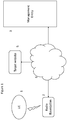
- Figure 1 depicts in schematic form a simplified network 6 connected to a network management system 3, an access point 2 and a target website server 5.
- a user terminal 1 can connect to the network 6 through the access point 2, and thereby communicate with the target website 5 and the management system 3. It will be recognised that in any practical system there will be many access points 2 and website servers 5 interconnected through the network 6, and each access point 2 may be connected to multiple user terminals 1.
- the access point 2 may be a domestic wireless router, femtocell or enterprise femtocell connected wirelessly to the user terminal 1, or they may have a wired connection (e.g Ethernet).
- a wireless access point is depicted schematically in more detail in Figure 2 .
- the functional elements depicted in Figure 2 are typically embodied in software or firmware.
- the access point 2 has a wireless interface 20 for communication with user terminals 1, and a network interface 22 for connection to a data communications network 6 such as the Internet. Data packets are translated from one medium to the other by a modem 23 and routing processes such as reading and writing address packets are is controlled by a routing function 21.
- a monitoring system 24 intercepts access requests generated by user terminals connected by the access point, and stores a record of such requests in a memory store 26.
- a counter 25 is used to determine the number of access requests made to each individual address, and this is used to update the store.
- a test generation system 27 is arranged to transmit access requests periodically to the addresses stored in the data store, by way of the modem 23 and network interface 22.
- a response monitor system 28 intercepts responses to these access requests, and controls an alert generation system 29 which is configured to process messages received over the network interface 22 in response to such requests by transmitting reports by way of the modem 23 and network 6 to the management entity 3.
- Figure 3 depicts a network management entity 3, which may be embodied in software, which co-operates with a number of access points 2 of the kind depicted in Figure 2 .
- the functional elements include a report reception function 30 which is configured to receive reports from the various access points about possible outages of network based server platforms such as the one depicted at 5 in Figure 1 .
- Such reports are stored in a database 31 for retrieval by a retrieval unit 32 which analyses the reports to identify patterns in the failure reports which may indicate a fault with a server 5 or with a user terminal 1, and reports to an appropriate fault management system 33, 34 accordingly.
- Figure 4 depicts a method for selecting which network addresses are to be monitored
- Figure 5 depicts the actual monitoring process. It should be noted that these processes can run concurrently, and in particular, the list of addresses to be monitored is continuously updated.
- the request monitor unit 24 in wireless access point 2 detects access requests made by the users and records a list of URLs (Internet Protocol addresses) that are regularly used by the customer. To do this it first stores the address identities in a temporary counting store 25 (step 40). At each such successful access attempt, a comparison is made with addresses already in the store 25 (step 41) and any address which occurs more than a predetermined number of times within a specified period t (for example five times in seven days) is forwarded to the main memory store 26. Each successful access attempt is removed from the temporary store (step 42) once the time window t has expired for that access attempt.
- URLs Internet Protocol addresses
- Addresses may be removed from the permanent store 26 if they have not been accessed for a longer predetermined period.
- the test generation system 27 identifies the addresses currently in the store 26 and tests each one from time to time to determine if they are still active, by sending an access request to each one (step 50) by way of the modem 23 and network interface 22. It is preferable that this is done when traffic is otherwise quiet, but it may be desirable to make successive tests on a particular website at different times of day as there may be a diurnal pattern of availability of certain websites which would not be detected if the test were made at the same time each day.
- the requests are flagged with an address corresponding to the response monitor unit 28 so that the responses are not forwarded to any of the user terminals.
- the response monitor unit 28 is alerted to the requests and responds accordingly when a response is received, according to the process depicted in Figure 5 . If any of these URLs 5 is not responding, or responds with an error message (step 51) a report is generated by the alert generation unit 29 and sent by way of the modem 23, network interface 22, and Internet 6, to the management entity 3.
- the input 30 of the management entity 3 receives reports from multiple access and stores them in a store 31 for analysis.
- the reports are analysed in a retrieval unit 32. If several access points report a failure of the same target network address 5, this is flagged as a potential fault with the target address and reported to a server fault management system 33, for example as a possible denial of service (DNS) issue.
- DNS denial of service
- the report analyser 32 may identify this as a potential problem with the access point, for example with its security settings or backhaul connection, and report to the backhaul fault management system 34. (It will be appreciated that only faults short of complete failure of the backhaul connection would be able to be reported in this way)
- the management entity 3 can process such reports to identify clusters or patterns to help identifying the cause of the issue. This allows the network operator to be more proactive, knowing about the issue and fixing it even before the customer notices. As the access point reports potential faults, fault detection can be determined even if no user terminal is currently connected to the access point, so that the problem can be reported to the network management system 3 before the user needs to use the address.
- the response monitor system 28 stores the status of the url, and when the next check is performed by the test generation system 27 the response is again analysed by the monitor unit. After a certain time t (step 54, 55) the test generation system performs another check.
- the process depicted in Figure 5 is arranged such that a change of status is reported to the management entity 3. If the address it is still returning a fault report (step 52) it does not inform the Management entity 3 again, but if it is has returned to activity the management entity is informed (step 53), so that the Management entity stops taking any further actions.
- the interval t' between tests may be shorter when a url is on record as faulty (step 55) than the time t when it is operating normally (step 54), so that updates are received more frequently.
Landscapes
- Engineering & Computer Science (AREA)
- Computer Networks & Wireless Communication (AREA)
- Signal Processing (AREA)
- Physics & Mathematics (AREA)
- Electromagnetism (AREA)
- Data Exchanges In Wide-Area Networks (AREA)
- Computer And Data Communications (AREA)
Claims (15)
- Procédé de surveillance d'un réseau de communication de données (6) pour identifier des pannes de ressources associées à des adresses de réseau en enregistrant sur un point d'accès (2) des tentatives d'accès réussies à des adresses de réseau (5) faites par des terminaux d'utilisateur (1) par l'intermédiaire du point d'accès (2) sur le réseau de communication de données au cours d'une période prédéterminée,
caractérisé en ce que des demandes de tentative de test (50) sont générées par un ou plusieurs points d'accès, et en ce que les demandes de tentative de test sont transmises à une pluralité d'adresses de réseau cibles (5), les adresses de réseau cibles étant des adresses pour lesquelles des tentatives d'accès réussies faites par des terminaux d'utilisateur ont été enregistrées, et en ce que toutes les éventuelles adresses de réseau qui ne parviennent pas à répondre à une demande à partir d'un point d'accès sont signalées (53) par le point d'accès à un système de gestion de réseau (3). - Procédé selon la revendication 1, dans lequel le système de gestion de réseau répond à de multiples signalements d'échecs (40) à partir de différents points d'accès concernant la même adresse de réseau en enregistrant la survenue d'une condition de défaillance potentielle associée à l'adresse de réseau.
- Procédé selon la revendication 1 ou la revendication 2, dans lequel le système de gestion de réseau (3) répond à de multiples échecs de tentatives d'accès à partir d'un point d'accès donné (2) en enregistrant la survenue d'une condition de défaillance potentielle associée au point d'accès.
- Procédé selon la revendication 1, la revendication 2 ou la revendication 3, dans lequel des tentatives d'accès par des terminaux d'utilisateur à chaque adresse sont comptées pendant une période prédéterminée (54), et dans lequel le point d'accès tente d'accéder périodiquement à des adresses qui ont été enregistrées comme ayant fait l'objet d'un accès par le point d'accès plus d'un nombre prédéterminé de fois.
- Procédé selon la revendication 1, la revendication 2, la revendication 3 ou la revendication 4, dans lequel les tentatives d'accès sont faites à différents moments de la journée.
- Procédé selon la revendication 1, la revendication 2, la revendication 3, la revendication 4 ou la revendication 5, dans lequel, à la suite d'une première tentative d'accès, une tentative d'accès ultérieure est faite après un intervalle (t, t') qui est sélectionné selon que la première tentative d'accès échoue ou réussit.
- Procédé selon la revendication 1, la revendication 2, la revendication 3, la revendication 4, la revendication 5 ou la revendication 6, dans lequel une alerte n'est transmise (53) au système de gestion à distance (3) que si une réponse reçue par le dispositif de surveillance de réponse (2), en réponse à une demande d'accès de test à une adresse de réseau (5), est différente d'une réponse précédente (51) reçue par le dispositif de surveillance de réponse en réponse à une demande d'accès de test précédente à la même adresse de réseau.
- Point d'accès (2) destiné à connecter un ou plusieurs terminaux d'utilisateur (1) à un réseau de communication de données (6), comportant un processeur de génération de test (27) destiné à générer des demandes d'accès de test pour une transmission sur le réseau de communication de données à des adresses de réseau cibles, un dispositif de surveillance de réponse (28) destiné à détecter des réponses aux demandes d'accès de test reçues en provenance des adresses de réseau cibles par l'intermédiaire du réseau de communication de données, et un processeur d'alerte (29) destiné à générer des signalements de réponses infructueuses aux demandes d'accès de test, pour une transmission à un système de gestion à distance,
caractérisé par un dispositif de surveillance de demandes d'accès (24) destiné à détecter et à enregistrer des demandes d'accès faites par des terminaux d'utilisateur connectés au point d'accès à des adresses de réseau cibles, qui sont des adresses pour lesquelles des tentatives d'accès réussies ont été enregistrées au cours d'une période prédéterminée, le processeur de génération de test (27) étant conçu pour générer des demandes d'accès de test pour leur transmission aux adresses cibles. - Point d'accès selon la revendication 8, comprenant un compteur (25) destiné à compter des tentatives d'accès à une adresse de réseau, et à commander le processeur de génération de test pour générer des demandes d'accès en réponse au fait que le compteur identifie un nombre prédéterminé de demandes en un temps prédéterminé.
- Point d'accès selon la revendication 8 ou la revendication 9, dans lequel le processeur de génération de test (27) est configuré pour générer des demandes d'accès de test à des moments échelonnés de la journée.
- Point d'accès selon la revendication 8, la revendication 9 ou la revendication 10, dans lequel le processeur de génération de test (27) est commandé par le dispositif de surveillance de réponse (28) pour générer des demandes d'accès de test à une adresse de réseau cible à un premier intervalle si le dispositif de surveillance de réponse (28) enregistre une réponse réussie à la demande précédente, et à un second intervalle plus court si le dispositif de surveillance de réponse enregistre une réponse infructueuse à la demande précédente.
- Point d'accès selon la revendication 8, la revendication 9 ou la revendication 10, dans lequel le processeur d'alerte (29) est configuré pour ne transmettre une alerte au système de gestion à distance (6) que si une réponse reçue par le dispositif de surveillance de réponse (28) en provenance d'une demande d'accès de test à une adresse de réseau cible est différente d'une réponse précédente reçue par le dispositif de surveillance de réponse en réponse à une demande d'accès de test précédente à la même adresse de réseau.
- Procédé de configuration à distance d'un dispositif programmable associé à un point d'accès (2) par transmission de données de programme au point d'accès de communication sur une connexion de communication de données, dans lequel le dispositif programmable, lorsqu'il exécute les données de programme, amène le point d'accès à fonctionner selon la revendication 8, la revendication 9, la revendication 10, la revendication 11, ou la revendication 12 ou la revendication 13.
- Système informatique associé à un point d'accès comprenant un processeur et une mémoire stockant un code de programme informatique destiné à mettre en œuvre les étapes du procédé selon la revendication 1, la revendication 2, la revendication 3, la revendication 4, la revendication 5, la revendication 6 ou la revendication 7 lorsque le code de programme informatique est exécuté par le processeur.
- Produit de programme informatique comprenant un code de programme informatique qui, lorsqu'il est chargé dans un système informatique associé à un point d'accès et exécuté sur celui-ci, amène le point d'accès à mettre en œuvre les étapes d'un procédé selon la revendication 1, la revendication 2, la revendication 3, la revendication 4, la revendication 5, la revendication 6 ou la revendication 7.
Applications Claiming Priority (2)
| Application Number | Priority Date | Filing Date | Title |
|---|---|---|---|
| EP17164621 | 2017-04-03 | ||
| PCT/EP2018/052281 WO2018184748A1 (fr) | 2017-04-03 | 2018-01-30 | Découverte de défaillance réseau |
Publications (2)
| Publication Number | Publication Date |
|---|---|
| EP3607767A1 EP3607767A1 (fr) | 2020-02-12 |
| EP3607767B1 true EP3607767B1 (fr) | 2022-01-05 |
Family
ID=58488919
Family Applications (1)
| Application Number | Title | Priority Date | Filing Date |
|---|---|---|---|
| EP18702487.2A Active EP3607767B1 (fr) | 2017-04-03 | 2018-01-30 | Découverte de panne de réseau |
Country Status (4)
| Country | Link |
|---|---|
| US (1) | US11153769B2 (fr) |
| EP (1) | EP3607767B1 (fr) |
| CN (1) | CN110521233B (fr) |
| WO (1) | WO2018184748A1 (fr) |
Families Citing this family (2)
| Publication number | Priority date | Publication date | Assignee | Title |
|---|---|---|---|---|
| EP3434041B1 (fr) | 2016-03-22 | 2023-10-11 | British Telecommunications public limited company | Rapport de panne d'émetteur |
| US11432359B1 (en) * | 2020-10-22 | 2022-08-30 | Sprint Spectrum L.P. | Use of access-block history as basis to dynamically control maximum number of connection-request transmissions per access attempt |
Family Cites Families (31)
| Publication number | Priority date | Publication date | Assignee | Title |
|---|---|---|---|---|
| EP1391100A4 (fr) | 2001-05-02 | 2009-03-11 | Strix Systems Inc | Decouverte de voisins d'une station de base sans fil dans un systeme de communication utilisant un plan de sauts de frequence a faible portee |
| US7543051B2 (en) * | 2003-05-30 | 2009-06-02 | Borland Software Corporation | Method of non-intrusive analysis of secure and non-secure web application traffic in real-time |
| US7826820B2 (en) | 2006-09-08 | 2010-11-02 | Telefonaktiebolaget Lm Ericsson (Publ) | Non-homogenous telecommunications base stations |
| WO2008156782A2 (fr) | 2007-06-19 | 2008-12-24 | Sand Holdings, Llc | Systèmes, dispositifs, agents et procédés pour la surveillance et le redémarrage et la restauration automatiques d'ordinateurs, de réseaux locaux, de points d'accès sans fil, de modems et d'autres matériels |
| US8116815B2 (en) | 2007-11-05 | 2012-02-14 | Hewlett-Packard Development Company, L.P. | Systems and methods for maintaining base stations in wireless networks |
| US7864687B2 (en) | 2007-12-19 | 2011-01-04 | At&T Intellectual Property Ii, L.P. | Methods and apparatus for fault identification in border gateway protocol networks |
| US8527663B2 (en) * | 2007-12-21 | 2013-09-03 | At&T Intellectual Property I, L.P. | Methods and apparatus for performing non-intrusive network layer performance measurement in communication networks |
| EP2154918B1 (fr) | 2008-08-13 | 2012-02-01 | Alcatel Lucent | Procédé décentralisé pour le traitement d'une panne de cellule dans un réseau de radiocommunication |
| EP2528279A3 (fr) | 2009-02-13 | 2013-03-27 | Nokia Siemens Networks Oy | Procédé, système et nýuds pour la détection de la topologie dýun réseau dans des réseaux de communication |
| EP2230864B1 (fr) | 2009-03-17 | 2020-01-08 | Alcatel Lucent | Détection de fautes dans des stations de base |
| CN101583150B (zh) | 2009-06-18 | 2011-04-20 | 中兴通讯股份有限公司 | 一种无线接入点检测无线终端异常的方法及装置 |
| US8407247B2 (en) | 2010-02-22 | 2013-03-26 | Kenshoo Ltd. | Universal resource locator watchdog |
| CN102752788B (zh) | 2011-04-20 | 2015-12-16 | 华为技术有限公司 | 检测失效小区的方法和设备 |
| WO2013094092A1 (fr) | 2011-12-22 | 2013-06-27 | 日本電気株式会社 | Station de base, système de communication et procédé de commande de station de base |
| CN103220695B (zh) | 2012-01-20 | 2017-04-12 | 华为技术有限公司 | 网元状态的处理方法及装置 |
| US8873403B2 (en) | 2012-02-21 | 2014-10-28 | Avaya Inc. | System and method for automatic DSCP tracing for XoIP elements |
| US8811291B2 (en) * | 2012-05-30 | 2014-08-19 | Qualcomm Incorporated | Methods and devices for optimized cell acquisitions |
| EP2770772B1 (fr) | 2013-02-26 | 2015-04-08 | Alcatel Lucent | Procédé de compensation de défaillance de cellules et noeud de réseau |
| US9331900B2 (en) | 2013-07-03 | 2016-05-03 | Fortinet, Inc. | Centralized management of access points |
| US9571363B2 (en) * | 2013-07-15 | 2017-02-14 | Centurylink Intellectual Property Llc | Control groups for network testing |
| US20150058481A1 (en) | 2013-08-22 | 2015-02-26 | Bruce D. Miller | Method & apparatus for measuring power, bandwidth and monitoring the operation of a network infrastructure from another network infrastructure |
| CN105794253B (zh) * | 2013-11-28 | 2017-11-28 | 英国电讯有限公司 | 无线接入点和报告连接的丢失的方法 |
| WO2015160296A1 (fr) | 2014-04-17 | 2015-10-22 | Telefonaktiebolaget L M Ericsson (Publ) | Procédés et stations de base pour des économies d'énergie dans une station de base domestique |
| US9338651B2 (en) | 2014-05-09 | 2016-05-10 | Verizon Patent And Licensing Inc. | Proactive assistance in obtaining a wireless network connection |
| US9930098B2 (en) * | 2015-01-23 | 2018-03-27 | Hughes Network Systems, Llc | Method and system for ISP network performance monitoring and fault detection |
| US10034149B2 (en) | 2016-03-02 | 2018-07-24 | Cisco Technology, Inc. | System and method for providing home node B gateway redundancy in a network environment |
| EP3434040B1 (fr) | 2016-03-22 | 2022-03-02 | British Telecommunications public limited company | Émetteur de détection d'une panne de courant |
| EP3434041B1 (fr) | 2016-03-22 | 2023-10-11 | British Telecommunications public limited company | Rapport de panne d'émetteur |
| CN105873053B (zh) * | 2016-03-29 | 2020-04-10 | 上海斐讯数据通信技术有限公司 | 一种接入认证页面嵌入网页的方法、系统及无线接入点 |
| CN106130810B (zh) * | 2016-06-01 | 2020-12-22 | 北京百度网讯科技有限公司 | 网站监测方法和装置 |
| US10912004B2 (en) | 2016-10-28 | 2021-02-02 | British Telecommunications Public Limited Company | Method of handling a cell outage in a radiocommunication network |
-
2018
- 2018-01-30 EP EP18702487.2A patent/EP3607767B1/fr active Active
- 2018-01-30 US US16/500,589 patent/US11153769B2/en active Active
- 2018-01-30 WO PCT/EP2018/052281 patent/WO2018184748A1/fr not_active Ceased
- 2018-01-30 CN CN201880023262.6A patent/CN110521233B/zh active Active
Also Published As
| Publication number | Publication date |
|---|---|
| US11153769B2 (en) | 2021-10-19 |
| CN110521233B (zh) | 2023-04-25 |
| CN110521233A (zh) | 2019-11-29 |
| US20200196172A1 (en) | 2020-06-18 |
| WO2018184748A1 (fr) | 2018-10-11 |
| EP3607767A1 (fr) | 2020-02-12 |
Similar Documents
| Publication | Publication Date | Title |
|---|---|---|
| US11632320B2 (en) | Centralized analytical monitoring of IP connected devices | |
| US10931730B2 (en) | Method and system for ISP network performance monitoring and fault detection | |
| US8443074B2 (en) | Constructing an inference graph for a network | |
| US7640460B2 (en) | Detect user-perceived faults using packet traces in enterprise networks | |
| CN118869453A (zh) | 故障检测方法 | |
| CN104883282A (zh) | 终端的dns服务器的监控方法及系统 | |
| KR102376433B1 (ko) | 멀티네트워크 디바이스의 보안 진단 방법 | |
| JP6220625B2 (ja) | 遅延監視システムおよび遅延監視方法 | |
| EP3607767B1 (fr) | Découverte de panne de réseau | |
| KR100908131B1 (ko) | 로그 필터링을 통한 장애 감지 장치 및 그 방법과 그장치를 이용한 장애 감지 시스템 | |
| CN119835188A (zh) | 检测无线接入点中客户端连接性和流量中的降级 | |
| JP2011090429A (ja) | 統合監視システム | |
| KR102369991B1 (ko) | IoT 멀티네트워크의 보안을 위한 통합 관리 시스템 | |
| KR101556781B1 (ko) | 네트웍 장비 예측 장애 및 수명 정보 서비스 시스템 | |
| JP6926646B2 (ja) | 事業者間一括サービス管理装置および事業者間一括サービス管理方法 | |
| CN116841834A (zh) | 状态调节方法和装置、存储介质及电子装置 | |
| JP6488600B2 (ja) | 情報処理システム、プログラム及び情報処理装置 | |
| CN111708689B (zh) | 一种修改ab实验的方法、装置及电子设备 | |
| GB2561181A (en) | Network Fault Discovery | |
| KR101490316B1 (ko) | 네트워크 장비의 장애 검출 시스템 및 이를 이용한 장애 검출 방법 | |
| KR102229613B1 (ko) | 머신러닝 자가점검 기능을 이용하는 비대면 인증 기반 웹방화벽 유지보수 방법 및 장치 | |
| CN110225543B (zh) | 基于网络请求数据的移动端软件质量态势感知系统及方法 | |
| CN115996408B (zh) | 一种故障处理方法、装置及电子设备 | |
| CN111064609A (zh) | 消息系统的主从切换方法、装置、电子设备及存储介质 | |
| CN120803782A (zh) | 应用平台的运行环境切换方法、装置、设备以及介质 |
Legal Events
| Date | Code | Title | Description |
|---|---|---|---|
| STAA | Information on the status of an ep patent application or granted ep patent |
Free format text: STATUS: UNKNOWN |
|
| STAA | Information on the status of an ep patent application or granted ep patent |
Free format text: STATUS: THE INTERNATIONAL PUBLICATION HAS BEEN MADE |
|
| PUAI | Public reference made under article 153(3) epc to a published international application that has entered the european phase |
Free format text: ORIGINAL CODE: 0009012 |
|
| STAA | Information on the status of an ep patent application or granted ep patent |
Free format text: STATUS: REQUEST FOR EXAMINATION WAS MADE |
|
| 17P | Request for examination filed |
Effective date: 20190917 |
|
| AK | Designated contracting states |
Kind code of ref document: A1 Designated state(s): AL AT BE BG CH CY CZ DE DK EE ES FI FR GB GR HR HU IE IS IT LI LT LU LV MC MK MT NL NO PL PT RO RS SE SI SK SM TR |
|
| AX | Request for extension of the european patent |
Extension state: BA ME |
|
| DAV | Request for validation of the european patent (deleted) | ||
| DAX | Request for extension of the european patent (deleted) | ||
| STAA | Information on the status of an ep patent application or granted ep patent |
Free format text: STATUS: EXAMINATION IS IN PROGRESS |
|
| 17Q | First examination report despatched |
Effective date: 20201026 |
|
| GRAP | Despatch of communication of intention to grant a patent |
Free format text: ORIGINAL CODE: EPIDOSNIGR1 |
|
| STAA | Information on the status of an ep patent application or granted ep patent |
Free format text: STATUS: GRANT OF PATENT IS INTENDED |
|
| RIC1 | Information provided on ipc code assigned before grant |
Ipc: H04W 24/00 20090101AFI20210705BHEP Ipc: H04W 88/08 20090101ALN20210705BHEP |
|
| INTG | Intention to grant announced |
Effective date: 20210802 |
|
| GRAS | Grant fee paid |
Free format text: ORIGINAL CODE: EPIDOSNIGR3 |
|
| GRAA | (expected) grant |
Free format text: ORIGINAL CODE: 0009210 |
|
| STAA | Information on the status of an ep patent application or granted ep patent |
Free format text: STATUS: THE PATENT HAS BEEN GRANTED |
|
| AK | Designated contracting states |
Kind code of ref document: B1 Designated state(s): AL AT BE BG CH CY CZ DE DK EE ES FI FR GB GR HR HU IE IS IT LI LT LU LV MC MK MT NL NO PL PT RO RS SE SI SK SM TR |
|
| REG | Reference to a national code |
Ref country code: GB Ref legal event code: FG4D |
|
| REG | Reference to a national code |
Ref country code: CH Ref legal event code: EP |
|
| REG | Reference to a national code |
Ref country code: AT Ref legal event code: REF Ref document number: 1461680 Country of ref document: AT Kind code of ref document: T Effective date: 20220115 |
|
| REG | Reference to a national code |
Ref country code: DE Ref legal event code: R096 Ref document number: 602018029079 Country of ref document: DE |
|
| REG | Reference to a national code |
Ref country code: IE Ref legal event code: FG4D |
|
| RAP4 | Party data changed (patent owner data changed or rights of a patent transferred) |
Owner name: BRITISH TELECOMMUNICATIONS PUBLIC LIMITED COMPANY |
|
| REG | Reference to a national code |
Ref country code: LT Ref legal event code: MG9D |
|
| REG | Reference to a national code |
Ref country code: NL Ref legal event code: MP Effective date: 20220105 |
|
| REG | Reference to a national code |
Ref country code: AT Ref legal event code: MK05 Ref document number: 1461680 Country of ref document: AT Kind code of ref document: T Effective date: 20220105 |
|
| PG25 | Lapsed in a contracting state [announced via postgrant information from national office to epo] |
Ref country code: NL Free format text: LAPSE BECAUSE OF FAILURE TO SUBMIT A TRANSLATION OF THE DESCRIPTION OR TO PAY THE FEE WITHIN THE PRESCRIBED TIME-LIMIT Effective date: 20220105 |
|
| PG25 | Lapsed in a contracting state [announced via postgrant information from national office to epo] |
Ref country code: SE Free format text: LAPSE BECAUSE OF FAILURE TO SUBMIT A TRANSLATION OF THE DESCRIPTION OR TO PAY THE FEE WITHIN THE PRESCRIBED TIME-LIMIT Effective date: 20220105 Ref country code: RS Free format text: LAPSE BECAUSE OF FAILURE TO SUBMIT A TRANSLATION OF THE DESCRIPTION OR TO PAY THE FEE WITHIN THE PRESCRIBED TIME-LIMIT Effective date: 20220105 Ref country code: PT Free format text: LAPSE BECAUSE OF FAILURE TO SUBMIT A TRANSLATION OF THE DESCRIPTION OR TO PAY THE FEE WITHIN THE PRESCRIBED TIME-LIMIT Effective date: 20220505 Ref country code: NO Free format text: LAPSE BECAUSE OF FAILURE TO SUBMIT A TRANSLATION OF THE DESCRIPTION OR TO PAY THE FEE WITHIN THE PRESCRIBED TIME-LIMIT Effective date: 20220405 Ref country code: LT Free format text: LAPSE BECAUSE OF FAILURE TO SUBMIT A TRANSLATION OF THE DESCRIPTION OR TO PAY THE FEE WITHIN THE PRESCRIBED TIME-LIMIT Effective date: 20220105 Ref country code: HR Free format text: LAPSE BECAUSE OF FAILURE TO SUBMIT A TRANSLATION OF THE DESCRIPTION OR TO PAY THE FEE WITHIN THE PRESCRIBED TIME-LIMIT Effective date: 20220105 Ref country code: ES Free format text: LAPSE BECAUSE OF FAILURE TO SUBMIT A TRANSLATION OF THE DESCRIPTION OR TO PAY THE FEE WITHIN THE PRESCRIBED TIME-LIMIT Effective date: 20220105 Ref country code: BG Free format text: LAPSE BECAUSE OF FAILURE TO SUBMIT A TRANSLATION OF THE DESCRIPTION OR TO PAY THE FEE WITHIN THE PRESCRIBED TIME-LIMIT Effective date: 20220405 |
|
| PG25 | Lapsed in a contracting state [announced via postgrant information from national office to epo] |
Ref country code: PL Free format text: LAPSE BECAUSE OF FAILURE TO SUBMIT A TRANSLATION OF THE DESCRIPTION OR TO PAY THE FEE WITHIN THE PRESCRIBED TIME-LIMIT Effective date: 20220105 Ref country code: LV Free format text: LAPSE BECAUSE OF FAILURE TO SUBMIT A TRANSLATION OF THE DESCRIPTION OR TO PAY THE FEE WITHIN THE PRESCRIBED TIME-LIMIT Effective date: 20220105 Ref country code: GR Free format text: LAPSE BECAUSE OF FAILURE TO SUBMIT A TRANSLATION OF THE DESCRIPTION OR TO PAY THE FEE WITHIN THE PRESCRIBED TIME-LIMIT Effective date: 20220406 Ref country code: FI Free format text: LAPSE BECAUSE OF FAILURE TO SUBMIT A TRANSLATION OF THE DESCRIPTION OR TO PAY THE FEE WITHIN THE PRESCRIBED TIME-LIMIT Effective date: 20220105 Ref country code: AT Free format text: LAPSE BECAUSE OF FAILURE TO SUBMIT A TRANSLATION OF THE DESCRIPTION OR TO PAY THE FEE WITHIN THE PRESCRIBED TIME-LIMIT Effective date: 20220105 |
|
| REG | Reference to a national code |
Ref country code: CH Ref legal event code: PL |
|
| PG25 | Lapsed in a contracting state [announced via postgrant information from national office to epo] |
Ref country code: IS Free format text: LAPSE BECAUSE OF FAILURE TO SUBMIT A TRANSLATION OF THE DESCRIPTION OR TO PAY THE FEE WITHIN THE PRESCRIBED TIME-LIMIT Effective date: 20220505 |
|
| REG | Reference to a national code |
Ref country code: BE Ref legal event code: MM Effective date: 20220131 |
|
| REG | Reference to a national code |
Ref country code: DE Ref legal event code: R097 Ref document number: 602018029079 Country of ref document: DE |
|
| PG25 | Lapsed in a contracting state [announced via postgrant information from national office to epo] |
Ref country code: SM Free format text: LAPSE BECAUSE OF FAILURE TO SUBMIT A TRANSLATION OF THE DESCRIPTION OR TO PAY THE FEE WITHIN THE PRESCRIBED TIME-LIMIT Effective date: 20220105 Ref country code: SK Free format text: LAPSE BECAUSE OF FAILURE TO SUBMIT A TRANSLATION OF THE DESCRIPTION OR TO PAY THE FEE WITHIN THE PRESCRIBED TIME-LIMIT Effective date: 20220105 Ref country code: RO Free format text: LAPSE BECAUSE OF FAILURE TO SUBMIT A TRANSLATION OF THE DESCRIPTION OR TO PAY THE FEE WITHIN THE PRESCRIBED TIME-LIMIT Effective date: 20220105 Ref country code: MC Free format text: LAPSE BECAUSE OF FAILURE TO SUBMIT A TRANSLATION OF THE DESCRIPTION OR TO PAY THE FEE WITHIN THE PRESCRIBED TIME-LIMIT Effective date: 20220105 Ref country code: LU Free format text: LAPSE BECAUSE OF NON-PAYMENT OF DUE FEES Effective date: 20220130 Ref country code: EE Free format text: LAPSE BECAUSE OF FAILURE TO SUBMIT A TRANSLATION OF THE DESCRIPTION OR TO PAY THE FEE WITHIN THE PRESCRIBED TIME-LIMIT Effective date: 20220105 Ref country code: DK Free format text: LAPSE BECAUSE OF FAILURE TO SUBMIT A TRANSLATION OF THE DESCRIPTION OR TO PAY THE FEE WITHIN THE PRESCRIBED TIME-LIMIT Effective date: 20220105 Ref country code: CZ Free format text: LAPSE BECAUSE OF FAILURE TO SUBMIT A TRANSLATION OF THE DESCRIPTION OR TO PAY THE FEE WITHIN THE PRESCRIBED TIME-LIMIT Effective date: 20220105 |
|
| PLBE | No opposition filed within time limit |
Free format text: ORIGINAL CODE: 0009261 |
|
| STAA | Information on the status of an ep patent application or granted ep patent |
Free format text: STATUS: NO OPPOSITION FILED WITHIN TIME LIMIT |
|
| PG25 | Lapsed in a contracting state [announced via postgrant information from national office to epo] |
Ref country code: BE Free format text: LAPSE BECAUSE OF NON-PAYMENT OF DUE FEES Effective date: 20220131 Ref country code: AL Free format text: LAPSE BECAUSE OF FAILURE TO SUBMIT A TRANSLATION OF THE DESCRIPTION OR TO PAY THE FEE WITHIN THE PRESCRIBED TIME-LIMIT Effective date: 20220105 |
|
| 26N | No opposition filed |
Effective date: 20221006 |
|
| PG25 | Lapsed in a contracting state [announced via postgrant information from national office to epo] |
Ref country code: LI Free format text: LAPSE BECAUSE OF NON-PAYMENT OF DUE FEES Effective date: 20220131 Ref country code: CH Free format text: LAPSE BECAUSE OF NON-PAYMENT OF DUE FEES Effective date: 20220131 |
|
| PG25 | Lapsed in a contracting state [announced via postgrant information from national office to epo] |
Ref country code: IE Free format text: LAPSE BECAUSE OF NON-PAYMENT OF DUE FEES Effective date: 20220130 |
|
| PG25 | Lapsed in a contracting state [announced via postgrant information from national office to epo] |
Ref country code: SI Free format text: LAPSE BECAUSE OF FAILURE TO SUBMIT A TRANSLATION OF THE DESCRIPTION OR TO PAY THE FEE WITHIN THE PRESCRIBED TIME-LIMIT Effective date: 20220105 |
|
| PG25 | Lapsed in a contracting state [announced via postgrant information from national office to epo] |
Ref country code: IT Free format text: LAPSE BECAUSE OF FAILURE TO SUBMIT A TRANSLATION OF THE DESCRIPTION OR TO PAY THE FEE WITHIN THE PRESCRIBED TIME-LIMIT Effective date: 20220105 |
|
| P01 | Opt-out of the competence of the unified patent court (upc) registered |
Effective date: 20230623 |
|
| PG25 | Lapsed in a contracting state [announced via postgrant information from national office to epo] |
Ref country code: MK Free format text: LAPSE BECAUSE OF FAILURE TO SUBMIT A TRANSLATION OF THE DESCRIPTION OR TO PAY THE FEE WITHIN THE PRESCRIBED TIME-LIMIT Effective date: 20220105 Ref country code: CY Free format text: LAPSE BECAUSE OF FAILURE TO SUBMIT A TRANSLATION OF THE DESCRIPTION OR TO PAY THE FEE WITHIN THE PRESCRIBED TIME-LIMIT Effective date: 20220105 |
|
| PG25 | Lapsed in a contracting state [announced via postgrant information from national office to epo] |
Ref country code: HU Free format text: LAPSE BECAUSE OF FAILURE TO SUBMIT A TRANSLATION OF THE DESCRIPTION OR TO PAY THE FEE WITHIN THE PRESCRIBED TIME-LIMIT; INVALID AB INITIO Effective date: 20180130 |
|
| PG25 | Lapsed in a contracting state [announced via postgrant information from national office to epo] |
Ref country code: MT Free format text: LAPSE BECAUSE OF FAILURE TO SUBMIT A TRANSLATION OF THE DESCRIPTION OR TO PAY THE FEE WITHIN THE PRESCRIBED TIME-LIMIT Effective date: 20220105 |
|
| PG25 | Lapsed in a contracting state [announced via postgrant information from national office to epo] |
Ref country code: TR Free format text: LAPSE BECAUSE OF FAILURE TO SUBMIT A TRANSLATION OF THE DESCRIPTION OR TO PAY THE FEE WITHIN THE PRESCRIBED TIME-LIMIT Effective date: 20220105 |
|
| PGFP | Annual fee paid to national office [announced via postgrant information from national office to epo] |
Ref country code: GB Payment date: 20251217 Year of fee payment: 9 |
|
| PGFP | Annual fee paid to national office [announced via postgrant information from national office to epo] |
Ref country code: FR Payment date: 20251217 Year of fee payment: 9 |
|
| PGFP | Annual fee paid to national office [announced via postgrant information from national office to epo] |
Ref country code: DE Payment date: 20251217 Year of fee payment: 9 |