EP3613977A1 - Embedded electric machine - Google Patents
Embedded electric machine Download PDFInfo
- Publication number
- EP3613977A1 EP3613977A1 EP19192489.3A EP19192489A EP3613977A1 EP 3613977 A1 EP3613977 A1 EP 3613977A1 EP 19192489 A EP19192489 A EP 19192489A EP 3613977 A1 EP3613977 A1 EP 3613977A1
- Authority
- EP
- European Patent Office
- Prior art keywords
- electric machine
- gas turbine
- turbine engine
- mount
- rotor
- Prior art date
- Legal status (The legal status is an assumption and is not a legal conclusion. Google has not performed a legal analysis and makes no representation as to the accuracy of the status listed.)
- Granted
Links
Images



Classifications
-
- F—MECHANICAL ENGINEERING; LIGHTING; HEATING; WEAPONS; BLASTING
- F01—MACHINES OR ENGINES IN GENERAL; ENGINE PLANTS IN GENERAL; STEAM ENGINES
- F01D—NON-POSITIVE DISPLACEMENT MACHINES OR ENGINES, e.g. STEAM TURBINES
- F01D15/00—Adaptations of machines or engines for special use; Combinations of engines with devices driven thereby
- F01D15/10—Adaptations for driving, or combinations with, electric generators
-
- B—PERFORMING OPERATIONS; TRANSPORTING
- B64—AIRCRAFT; AVIATION; COSMONAUTICS
- B64D—EQUIPMENT FOR FITTING IN OR TO AIRCRAFT; FLIGHT SUITS; PARACHUTES; ARRANGEMENT OR MOUNTING OF POWER PLANTS OR PROPULSION TRANSMISSIONS IN AIRCRAFT
- B64D27/00—Arrangement or mounting of power plants in aircraft; Aircraft characterised by the type or position of power plants
- B64D27/02—Aircraft characterised by the type or position of power plants
- B64D27/10—Aircraft characterised by the type or position of power plants of gas-turbine type
-
- B—PERFORMING OPERATIONS; TRANSPORTING
- B64—AIRCRAFT; AVIATION; COSMONAUTICS
- B64D—EQUIPMENT FOR FITTING IN OR TO AIRCRAFT; FLIGHT SUITS; PARACHUTES; ARRANGEMENT OR MOUNTING OF POWER PLANTS OR PROPULSION TRANSMISSIONS IN AIRCRAFT
- B64D27/00—Arrangement or mounting of power plants in aircraft; Aircraft characterised by the type or position of power plants
- B64D27/02—Aircraft characterised by the type or position of power plants
- B64D27/30—Aircraft characterised by electric power plants
- B64D27/33—Hybrid electric aircraft
-
- B—PERFORMING OPERATIONS; TRANSPORTING
- B64—AIRCRAFT; AVIATION; COSMONAUTICS
- B64F—GROUND OR AIRCRAFT-CARRIER-DECK INSTALLATIONS SPECIALLY ADAPTED FOR USE IN CONNECTION WITH AIRCRAFT; DESIGNING, MANUFACTURING, ASSEMBLING, CLEANING, MAINTAINING OR REPAIRING AIRCRAFT, NOT OTHERWISE PROVIDED FOR; HANDLING, TRANSPORTING, TESTING OR INSPECTING AIRCRAFT COMPONENTS, NOT OTHERWISE PROVIDED FOR
- B64F5/00—Designing, manufacturing, assembling, cleaning, maintaining or repairing aircraft, not otherwise provided for; Handling, transporting, testing or inspecting aircraft components, not otherwise provided for
- B64F5/40—Maintaining or repairing aircraft
-
- F—MECHANICAL ENGINEERING; LIGHTING; HEATING; WEAPONS; BLASTING
- F01—MACHINES OR ENGINES IN GENERAL; ENGINE PLANTS IN GENERAL; STEAM ENGINES
- F01D—NON-POSITIVE DISPLACEMENT MACHINES OR ENGINES, e.g. STEAM TURBINES
- F01D25/00—Component parts, details, or accessories, not provided for in, or of interest apart from, other groups
- F01D25/28—Supporting or mounting arrangements, e.g. for turbine casing
-
- F—MECHANICAL ENGINEERING; LIGHTING; HEATING; WEAPONS; BLASTING
- F02—COMBUSTION ENGINES; HOT-GAS OR COMBUSTION-PRODUCT ENGINE PLANTS
- F02C—GAS-TURBINE PLANTS; AIR INTAKES FOR JET-PROPULSION PLANTS; CONTROLLING FUEL SUPPLY IN AIR-BREATHING JET-PROPULSION PLANTS
- F02C6/00—Plural gas-turbine plants; Combinations of gas-turbine plants with other apparatus; Adaptations of gas-turbine plants for special use
-
- F—MECHANICAL ENGINEERING; LIGHTING; HEATING; WEAPONS; BLASTING
- F02—COMBUSTION ENGINES; HOT-GAS OR COMBUSTION-PRODUCT ENGINE PLANTS
- F02C—GAS-TURBINE PLANTS; AIR INTAKES FOR JET-PROPULSION PLANTS; CONTROLLING FUEL SUPPLY IN AIR-BREATHING JET-PROPULSION PLANTS
- F02C6/00—Plural gas-turbine plants; Combinations of gas-turbine plants with other apparatus; Adaptations of gas-turbine plants for special use
- F02C6/14—Gas-turbine plants having means for storing energy, e.g. for meeting peak loads
-
- F—MECHANICAL ENGINEERING; LIGHTING; HEATING; WEAPONS; BLASTING
- F02—COMBUSTION ENGINES; HOT-GAS OR COMBUSTION-PRODUCT ENGINE PLANTS
- F02C—GAS-TURBINE PLANTS; AIR INTAKES FOR JET-PROPULSION PLANTS; CONTROLLING FUEL SUPPLY IN AIR-BREATHING JET-PROPULSION PLANTS
- F02C7/00—Features, components parts, details or accessories, not provided for in, or of interest apart form groups F02C1/00 - F02C6/00; Air intakes for jet-propulsion plants
- F02C7/32—Arrangement, mounting, or driving, of auxiliaries
-
- F—MECHANICAL ENGINEERING; LIGHTING; HEATING; WEAPONS; BLASTING
- F02—COMBUSTION ENGINES; HOT-GAS OR COMBUSTION-PRODUCT ENGINE PLANTS
- F02K—JET-PROPULSION PLANTS
- F02K5/00—Plants including an engine, other than a gas turbine, driving a compressor or a ducted fan
-
- B—PERFORMING OPERATIONS; TRANSPORTING
- B64—AIRCRAFT; AVIATION; COSMONAUTICS
- B64D—EQUIPMENT FOR FITTING IN OR TO AIRCRAFT; FLIGHT SUITS; PARACHUTES; ARRANGEMENT OR MOUNTING OF POWER PLANTS OR PROPULSION TRANSMISSIONS IN AIRCRAFT
- B64D27/00—Arrangement or mounting of power plants in aircraft; Aircraft characterised by the type or position of power plants
- B64D27/02—Aircraft characterised by the type or position of power plants
- B64D27/026—Aircraft characterised by the type or position of power plants comprising different types of power plants, e.g. combination of a piston engine and a gas-turbine
-
- F—MECHANICAL ENGINEERING; LIGHTING; HEATING; WEAPONS; BLASTING
- F01—MACHINES OR ENGINES IN GENERAL; ENGINE PLANTS IN GENERAL; STEAM ENGINES
- F01D—NON-POSITIVE DISPLACEMENT MACHINES OR ENGINES, e.g. STEAM TURBINES
- F01D25/00—Component parts, details, or accessories, not provided for in, or of interest apart from, other groups
- F01D25/28—Supporting or mounting arrangements, e.g. for turbine casing
- F01D25/285—Temporary support structures, e.g. for testing, assembling, installing, repairing; Assembly methods using such structures
-
- F—MECHANICAL ENGINEERING; LIGHTING; HEATING; WEAPONS; BLASTING
- F05—INDEXING SCHEMES RELATING TO ENGINES OR PUMPS IN VARIOUS SUBCLASSES OF CLASSES F01-F04
- F05D—INDEXING SCHEME FOR ASPECTS RELATING TO NON-POSITIVE-DISPLACEMENT MACHINES OR ENGINES, GAS-TURBINES OR JET-PROPULSION PLANTS
- F05D2220/00—Application
- F05D2220/30—Application in turbines
- F05D2220/32—Application in turbines in gas turbines
- F05D2220/323—Application in turbines in gas turbines for aircraft propulsion, e.g. jet engines
-
- F—MECHANICAL ENGINEERING; LIGHTING; HEATING; WEAPONS; BLASTING
- F05—INDEXING SCHEMES RELATING TO ENGINES OR PUMPS IN VARIOUS SUBCLASSES OF CLASSES F01-F04
- F05D—INDEXING SCHEME FOR ASPECTS RELATING TO NON-POSITIVE-DISPLACEMENT MACHINES OR ENGINES, GAS-TURBINES OR JET-PROPULSION PLANTS
- F05D2220/00—Application
- F05D2220/70—Application in combination with
- F05D2220/76—Application in combination with an electrical generator
-
- F—MECHANICAL ENGINEERING; LIGHTING; HEATING; WEAPONS; BLASTING
- F05—INDEXING SCHEMES RELATING TO ENGINES OR PUMPS IN VARIOUS SUBCLASSES OF CLASSES F01-F04
- F05D—INDEXING SCHEME FOR ASPECTS RELATING TO NON-POSITIVE-DISPLACEMENT MACHINES OR ENGINES, GAS-TURBINES OR JET-PROPULSION PLANTS
- F05D2220/00—Application
- F05D2220/70—Application in combination with
- F05D2220/76—Application in combination with an electrical generator
- F05D2220/766—Application in combination with an electrical generator via a direct connection, i.e. a gearless transmission
-
- F—MECHANICAL ENGINEERING; LIGHTING; HEATING; WEAPONS; BLASTING
- F05—INDEXING SCHEMES RELATING TO ENGINES OR PUMPS IN VARIOUS SUBCLASSES OF CLASSES F01-F04
- F05D—INDEXING SCHEME FOR ASPECTS RELATING TO NON-POSITIVE-DISPLACEMENT MACHINES OR ENGINES, GAS-TURBINES OR JET-PROPULSION PLANTS
- F05D2230/00—Manufacture
- F05D2230/60—Assembly methods
-
- F—MECHANICAL ENGINEERING; LIGHTING; HEATING; WEAPONS; BLASTING
- F05—INDEXING SCHEMES RELATING TO ENGINES OR PUMPS IN VARIOUS SUBCLASSES OF CLASSES F01-F04
- F05D—INDEXING SCHEME FOR ASPECTS RELATING TO NON-POSITIVE-DISPLACEMENT MACHINES OR ENGINES, GAS-TURBINES OR JET-PROPULSION PLANTS
- F05D2230/00—Manufacture
- F05D2230/70—Disassembly methods
-
- F—MECHANICAL ENGINEERING; LIGHTING; HEATING; WEAPONS; BLASTING
- F05—INDEXING SCHEMES RELATING TO ENGINES OR PUMPS IN VARIOUS SUBCLASSES OF CLASSES F01-F04
- F05D—INDEXING SCHEME FOR ASPECTS RELATING TO NON-POSITIVE-DISPLACEMENT MACHINES OR ENGINES, GAS-TURBINES OR JET-PROPULSION PLANTS
- F05D2230/00—Manufacture
- F05D2230/72—Maintenance
-
- F—MECHANICAL ENGINEERING; LIGHTING; HEATING; WEAPONS; BLASTING
- F05—INDEXING SCHEMES RELATING TO ENGINES OR PUMPS IN VARIOUS SUBCLASSES OF CLASSES F01-F04
- F05D—INDEXING SCHEME FOR ASPECTS RELATING TO NON-POSITIVE-DISPLACEMENT MACHINES OR ENGINES, GAS-TURBINES OR JET-PROPULSION PLANTS
- F05D2230/00—Manufacture
- F05D2230/80—Repairing, retrofitting or upgrading methods
-
- Y—GENERAL TAGGING OF NEW TECHNOLOGICAL DEVELOPMENTS; GENERAL TAGGING OF CROSS-SECTIONAL TECHNOLOGIES SPANNING OVER SEVERAL SECTIONS OF THE IPC; TECHNICAL SUBJECTS COVERED BY FORMER USPC CROSS-REFERENCE ART COLLECTIONS [XRACs] AND DIGESTS
- Y02—TECHNOLOGIES OR APPLICATIONS FOR MITIGATION OR ADAPTATION AGAINST CLIMATE CHANGE
- Y02T—CLIMATE CHANGE MITIGATION TECHNOLOGIES RELATED TO TRANSPORTATION
- Y02T50/00—Aeronautics or air transport
- Y02T50/60—Efficient propulsion technologies, e.g. for aircraft
Definitions
- the present subject matter relates generally to a gas turbine engine having an embedded electric machine, and to a propulsion system for an aeronautical device including the same.
- Typical aircraft propulsion systems include one or more gas turbine engines.
- the gas turbine engines generally include a fan and a core arranged in flow communication with one another.
- the core of the gas turbine engine general includes, in serial flow order, a compressor section, a combustion section, a turbine section, and an exhaust section.
- air is provided from the fan to an inlet of the compressor section where one or more axial compressors progressively compress the air until it reaches the combustion section.
- Fuel is mixed with the compressed air and burned within the combustion section to provide combustion gases.
- the combustion gases are routed from the combustion section to the turbine section.
- the flow of combustion gasses through the turbine section drives the turbine section and is then routed through the exhaust section, e.g., to atmosphere.
- the propulsion system may include an electric fan to supplement propulsive power provided by the one or more gas turbine engines included with the propulsion system.
- providing the aircraft with a sufficient amount of energy storage devices to power the electric fan may be space and weight prohibitive.
- certain gas turbine engines may include auxiliary generators positioned, e.g., within a cowling of the gas turbine engine.
- these auxiliary generators may not be configured to provide a sufficient amount of electrical power to adequately drive the electric fan.
- a propulsion system for an aircraft including one or more electric machines embedded within the gas turbine engine would be useful.
- the inventors of the present disclosure have discovered that a useful life span of typical electric machines is less than that of a gas turbine engine. Accordingly, the electric machines embedded within the gas turbine engines may need to be repaired or replaced more frequently than the gas turbine engines themselves. However, in order to replace an embedded electric machine, the gas turbine engine must be taken off wing and disassembled to expose the electric machine and install a new electric machine. Such a set up may be timely and cost inefficient. Therefore, an improved gas turbine engine with an embedded electric machine would be useful, and a propulsion system including the same would also be beneficial.
- a method for maintaining a gas turbine engine installed on an aircraft, the gas turbine engine including an electric machine mounted at least partially inward of a core air flowpath of the gas turbine engine.
- the method includes removing a rotor mount connecting a rotor of the electric machine to a rotary component of the gas turbine engine; removing a stator mount connecting a stator of the electric machine to a stationary component of the gas turbine engine; and removing in situ the electric machine.
- the method further includes removing a cover assembly to expose the rotor mount, the stator mount, or both.
- the cover assembly includes an aft cone and a cavity wall.
- removing the rotor mount includes removing a mechanical connector connecting a shaft extension member to the rotor of the electric machine.
- removing the rotor mount further includes moving the shaft extension member at least partially along an axial direction of the gas turbine engine to decouple the shaft extension member from the rotary component of the gas turbine engine at a splined connection.
- removing in situ the electric machine includes disconnecting the electric machine from an electric communication bus.
- disconnecting the electric machine from the electric communication bus includes electrically disconnecting the electric machine from the electric communication bus at a quick release electric connection.
- the gas turbine engine extends between a forward end and an aft end, and wherein the electric machine is positioned at the aft end of the gas turbine engine.
- the electric machine defines an aft end, and wherein the rotor mount, the stator mount, or both are positioned proximate the aft end of the electric machine.
- the electric machine is a first electric machine, and wherein the method further includes installing in situ a second electric machine in place of the first electric machine.
- the method further includes connecting a rotor of the second electric machine to the rotary component of the gas turbine engine using the rotor mount; and connecting a stator of the second electric machine to the stationary component of the gas turbine engine using the stator mount.
- a gas turbine engine defining a radial direction and an axial direction.
- the gas turbine engine includes a turbomachine including a compressor, a turbine, a rotary component rotatable with the compressor and the turbine, and a stationary component, the compressor and turbine together defining at least in part a core air flowpath; an electric machine positioned at least partially inward of the core air flowpath along the radial direction, the electric machine including a rotor and a stator; a rotor mount removably coupling the rotor of the electric machine to the rotary component; a stator mount removably coupling the stator of the electric machine to the stationary component; and a cover assembly removably positioned over the electric machine, the electric machine and cover assembly positioned such that the electric machine is removable from the gas turbine engine in situ when the cover assembly is removed.
- the cover assembly includes an aft cone and a cavity wall.
- the cover assembly consists essentially of an aft cone and a cavity wall.
- the gas turbine engine further includes an electric communication bus; and a quick electric connection, the electric machine electrically connected to the electric communication bus through the quick electric connection.
- the gas turbine engine defines an aft end, and wherein the electric machine is positioned proximate the aft end.
- At least a portion of the cover assembly is visible from an outside of the gas turbine engine.
- the gas turbine engine further includes an electric machine mount coupled to, or formed integrally with, the stationary component of the turbomachine, and wherein the electric machine is slidably received on the electric machine mount.
- stator mount fixedly couples the electric machine to the electric machine mount.
- the gas turbine engine further includes a shaft extension member extending between a first end and a second end, wherein the first end is coupled to the rotary component of the turbomachine through a splined connection, and wherein the second end is coupled to the rotor of the electric machine by the rotor mount.
- first, second, and third may be used interchangeably to distinguish one component from another and are not intended to signify location or importance of the individual components.
- forward and aft refer to relative positions within a gas turbine engine or vehicle, and refer to the normal operational attitude of the gas turbine engine or vehicle.
- forward refers to a position closer to an engine inlet and aft refers to a position closer to an engine nozzle or exhaust.
- upstream and downstream refer to the relative direction with respect to fluid flow in a fluid pathway.
- upstream refers to the direction from which the fluid flows
- downstream refers to the direction to which the fluid flows.
- Coupled refers to both direct coupling, fixing, or attaching, as well as indirect coupling, fixing, or attaching through one or more intermediate components or features, unless otherwise specified herein.
- Approximating language is applied to modify any quantitative representation that could permissibly vary without resulting in a change in the basic function to which it is related. Accordingly, a value modified by a term or terms, such as “about”, “approximately”, and “substantially”, are not to be limited to the precise value specified. In at least some instances, the approximating language may correspond to the precision of an instrument for measuring the value, or the precision of the methods or machines for constructing or manufacturing the components and/or systems. For example, the approximating language may refer to being within a 10 percent margin.
- Fig. 1 provides a top view of an exemplary aircraft 10 as may incorporate various embodiments of the present invention.
- Fig. 2 provides a port side view of the aircraft 10 as illustrated in Fig. 1 .
- the aircraft 10 defines a longitudinal centerline 14 that extends therethrough, a vertical direction V, a lateral direction L, a forward end 16, and an aft end 18.
- the aircraft 10 defines a mean line 15 extending between the forward end 16 and aft end 18 of the aircraft 10.
- the "mean line” refers to a midpoint line extending along a length of the aircraft 10, not taking into account the appendages of the aircraft 10 (such as the wings 20 and stabilizers discussed below).
- the aircraft 10 includes a fuselage 12, extending longitudinally from the forward end 16 of the aircraft 10 towards the aft end 18 of the aircraft 10, and a pair of wings 20.
- fuselage generally includes all of the body of the aircraft 10, such as an empennage of the aircraft 10.
- the first of such wings 20 extends laterally outwardly with respect to the longitudinal centerline 14 from a port side 22 of the fuselage 12 and the second of such wings 20 extends laterally outwardly with respect to the longitudinal centerline 14 from a starboard side 24 of the fuselage 12.
- Each of the wings 20 for the exemplary embodiment depicted includes one or more leading edge flaps 26 and one or more trailing edge flaps 28.
- the aircraft 10 further includes a vertical stabilizer 30 having a rudder flap 32 for yaw control, and a pair of horizontal stabilizers 34, each having an elevator flap 36 for pitch control.
- the fuselage 12 additionally includes an outer surface or skin 38. It should be appreciated however, that in other exemplary embodiments of the present disclosure, the aircraft 10 may additionally or alternatively include any other suitable configuration of stabilizer that may or may not extend directly along the vertical direction V or horizontal/ lateral direction L.
- the exemplary aircraft 10 of Figs. 1 and 2 includes a propulsion system 100, herein referred to as "system 100".
- the exemplary system 100 includes one or more aircraft engines and one or more electric propulsion engines.
- the embodiment depicted includes a plurality of aircraft engines, each configured to be mounted to the aircraft 10, such as to one of the pair of wings 20, and an electric propulsion engine.
- the aircraft engines are configured as gas turbine engines, or rather as turbofan jet engines 102, 104 attached to and suspended beneath the wings 20 in an under-wing configuration.
- the electric propulsion engine is configured to be mounted at the aft end of the aircraft 10, and hence the electric propulsion engine depicted may be referred to as an "aft engine.” Further, the electric propulsion engine depicted is configured to ingest and consume air forming a boundary layer over the fuselage 12 of the aircraft 10. Accordingly, the exemplary aft engine depicted may be referred to as a boundary layer ingestion (BLI) fan 106.
- the BLI fan 106 is mounted to the aircraft 10 at a location aft of the wings 20 and/or the jet engines 102, 104.
- the BLI fan 106 is fixedly connected to the fuselage 12 at the aft end 18, such that the BLI fan 106 is incorporated into or blended with a tail section at the aft end 18, and such that the mean line 15 extends therethrough.
- the electric propulsion engine may be configured in any other suitable manner, and may not necessarily be configured as an aft fan or as a BLI fan.
- the propulsion system further includes one or more electric generators 108 operable with the jet engines 102, 104.
- the jet engines 102, 104 may be configured to provide mechanical power from a rotating shaft (such as an LP shaft or HP shaft) to the electric generators 108.
- a rotating shaft such as an LP shaft or HP shaft
- the electric generators 108 may be positioned within a respective jet engine 102, 104. Additionally, the electric generators 108 may be configured to convert the mechanical power to electrical power.
- the propulsion system 100 includes an electric generator 108 for each jet engine 102, 104, and also includes a power conditioner 109 and an energy storage device 110.
- the electric generators 108 may send electrical power to the power conditioner 109, which may transform the electrical energy to a proper form and either store the energy in the energy storage device 110 or send the electrical energy to the BLI fan 106.
- the electric generators 108, power conditioner 109, energy storage device 110, and BLI fan 106 are all are connected to an electric communication bus 111, such that the electric generator 108 may be in electrical communication with the BLI fan 106 and/or the energy storage device 110, and such that the electric generator 108 may provide electrical power to one or both of the energy storage device 110 or the BLI fan 106.
- the propulsion system 100 may be referred to as a gas-electric propulsion system.
- the aircraft 10 and propulsion system 100 depicted in Figs. 1 and 2 is provided by way of example only and that in other exemplary embodiments of the present disclosure, any other suitable aircraft 10 may be provided having any other suitable propulsion system 100 configured in any other suitable manner.
- the BLI fan 106 may alternatively be positioned at any suitable location proximate the aft end 18 of the aircraft 10.
- the electric propulsion engine may not be positioned at the aft end of the aircraft 10, and thus may not be configured as an "aft engine.”
- the electric propulsion engine may be incorporated into the fuselage of the aircraft 10, and thus configured as a "podded engine,” or pod-installation engine.
- the electric propulsion engine may be incorporated into a wing of the aircraft 10, and thus may be configured as a "blended wing engine.”
- the electric propulsion engine may not be a boundary layer ingestion fan, and instead may be mounted at any suitable location on the aircraft 10 as a freestream injection fan.
- the propulsion system 100 may not include, e.g., the power conditioner 109 and/or the energy storage device 110, and instead the generator(s) 108 may be directly electrically connected to the BLI fan 106.
- the propulsion engine may be configured a high-bypass turbofan jet engine 200, herein referred to as "turbofan 200."
- the jet engines 102, 104 may be also configured as high-bypass turbofan jet engines.
- the turbofan 200 may be representative of jet engines 102, 104.
- the turbofan 200 may be incorporated into any other suitable aircraft 10 or propulsion system 100.
- the turbofan 200 defines an axial direction A (extending parallel to a longitudinal centerline 201 provided for reference), a radial direction R, and a circumferential direction C (extending about the axial direction A; not depicted in Fig. 3 ).
- the turbofan 200 includes a fan section 202 and a turbomachine 204 disposed downstream from the fan section 202.
- the exemplary turbomachine 204 depicted generally includes a substantially tubular outer casing 206 that defines an annular inlet 208.
- the outer casing 206 encases, in serial flow relationship, a compressor section including a booster or low pressure (LP) compressor 210 and a high pressure (HP) compressor 212; a combustion section 214; a turbine section including a high pressure (HP) turbine 216 and a low pressure (LP) turbine 218; and a jet exhaust nozzle section 220.
- LP booster or low pressure
- HP high pressure
- HP high pressure
- LP low pressure
- the compressor section, combustion section 214, and turbine section together define a core air flowpath 221 extending from the annular inlet 208 through the LP compressor 210, HP compressor 212, combustion section 214, HP turbine section 216, LP turbine section 218 and jet nozzle exhaust section 220.
- a high pressure (HP) shaft or spool 222 drivingly connects the HP turbine 216 to the HP compressor 212.
- a low pressure (LP) shaft or spool 224 drivingly connects the LP turbine 218 to the LP compressor 210.
- the fan section 202 includes a variable pitch fan 226 having a plurality of fan blades 228 coupled to a disk 230 in a spaced apart manner.
- the fan blades 228 extend outwardly from disk 230 generally along the radial direction R.
- Each fan blade 228 is rotatable relative to the disk 230 about a pitch axis P by virtue of the fan blades 228 being operatively coupled to a suitable actuation member 232 configured to collectively vary the pitch of the fan blades 228 in unison.
- the fan blades 228, disk 230, and actuation member 232 are together rotatable about the longitudinal axis 12 by LP shaft 224 across a power gear box 234.
- the power gear box 234 includes a plurality of gears for stepping down the rotational speed of the LP shaft 224 to a more efficient rotational fan speed.
- the disk 230 is covered by rotatable front hub 236 aerodynamically contoured to promote an airflow through the plurality of fan blades 228.
- the exemplary fan section 202 includes an annular fan casing or outer nacelle 238 that circumferentially surrounds the fan 226 and/or at least a portion of the turbomachine 204.
- the nacelle 238 is supported relative to the turbomachine 204 by a plurality of circumferentially-spaced outlet guide vanes 240.
- a downstream section 242 of the nacelle 238 extends over an outer portion of the turbomachine 204 so as to define a bypass airflow passage 244 therebetween.
- the exemplary turbofan 200 depicted includes an electric machine 246 rotatable with the fan 226.
- the electric machine 246 is configured as an electric generator co-axially mounted to and rotatable with the LP shaft 224 (the LP shaft 224 also rotating the fan 226 through, for the embodiment depicted, the power gearbox 234).
- co-axially refers to the axes being aligned.
- an axis of the electric machine 246 may be offset radially from the axis of the LP shaft 224 and further may be oblique to the axis of the LP shaft 224, such that the electric machine 246 may be positioned at any suitable location at least partially inward of the core air flowpath 221.
- the electric machine 246 includes a rotor 248 and a stator 250.
- the rotor 248 and stator 250 of the electric machine 246 are configured in substantially the same manner as the exemplary rotor and stator of the electric machine described below.
- the electric generators 108 may be configured in substantially the same manner as the electric machine 246 of Fig. 3 .
- the gas turbine engine or rather, the turbofan engine 200, additionally includes a cover assembly 251 removably positioned over the electric machine 246.
- the electric machine 246 and cover assembly 251 are positioned such that the electric machine 246 is removable from the gas turbine engine (i.e., the turbofan engine 200) in situ when the cover assembly 251 is removed.
- the term "in situ,” with reference to a particular task or operation refers to such task or operation being completed with the engine still installed on or in the aircraft.
- turbofan engine 200 depicted in Fig. 3 is provided by way of example only, and that in other exemplary embodiments, the turbofan engine 200 may have any other suitable configuration.
- the turbofan engine 200 may be configured as a turboprop engine, a turbojet engine, a differently configured turbofan engine (e.g., direct drive engine, fixed-pitch engine, etc.), or any other suitable gas turbine engine.
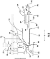
- an electric machine 246 embedded within a gas turbine engine in accordance with an exemplary embodiment of the present disclosure is depicted. More particularly, for the embodiment depicted, the electric machine 246 is embedded within a turbine section of the gas turbine engine, at a location inward of a core air flowpath 221 of the gas turbine engine. Additionally, the electric machine 246 is positioned at least partially within or aft of the turbine section along an axial direction A.
- the electric machine 246 and gas turbine engine depicted in Fig. 4 may be configured in substantially the same manner as the exemplary electric machine 246 and turbofan engine 200 described above with reference to Fig. 3 . Accordingly, the same or similar numbers may refer to the same or similar parts.
- the gas turbine engine generally includes a rotary component and a stationary component.
- the rotary component is rotatable with a compressor within a compressor section (not shown) of the gas turbine engine and a turbine within the turbine section of the gas turbine engine.
- the stationary component may be any suitable component which is configured to remain stationary relative to the various rotating components of the compressors and turbines.
- the electric machine 246 generally includes a rotor 248 and a stator 250.
- the rotor 248 of the electric machine 246 is coupled to the rotary component of the gas turbine engine and the stator 250 of the electric machine 246 is coupled to the stationary component of the gas turbine engine.
- the rotary component to which the rotor 248 of the electric machine 246 is coupled is an LP shaft 224 of the gas turbine engine, such that the rotor 248 is rotatable with the LP shaft 224.
- the stationary component to which the stator 250 of the electric machine 246 is coupled is a structural support member 256 of the turbine section.
- the structural support member 256 is configured as part of an aft frame assembly and extends from an aft frame strut 258 of the aft frame assembly of the gas turbine engine.
- the aft strut 258 extends through the core air flowpath 221 of the gas turbine engine, and is configured to provide structural support for the gas turbine engine.
- the structural support member 256 also extends forward to support an aft engine bearing 260-the aft engine bearing 260 rotatably supporting an aft end of the LP shaft 224.
- the gas turbine engine defines an electric machine sump 262.
- the electric machine sump 262 extends from a location forward of the electric machine 246 continuously to a location aft of the electric machine 246.
- the gas turbine engine depicted includes an electric machine lubrication system 264, with the electric machine lubrication system 264 in fluid communication with the electric machine sump 262, for providing a thermal fluid to the electric machine sump 262.
- the electric machine lubrication system 264 may operate independently of a gas turbine engine lubrication system.
- the cooling system of the exemplary gas turbine engine depicted further includes a buffer cavity 266 surrounding at least a portion of the electric machine 246.
- the buffer cavity 266 may further thermally insulate the electric machine 246.
- the buffer cavity 266, for the embodiment depicted, extends continuously from a location forward of the electric machine 246 to a location aft of the electric machine 246 along the axial direction A.
- the buffer cavity 266 may act as an insulator from relatively hot operating temperatures within the core air flowpath 221 extending through the turbine section of the gas turbine engine.
- the gas turbine engine includes a cooling duct 268.
- the cooling duct 268 is in airflow communication with the buffer cavity 266 for providing a cooling airflow to the buffer cavity 266.
- the cooling duct 268 defines an outlet (not labeled) extending through the structural support member 256 for providing the cooling airflow from the cooling duct 268 through the structural support member 256 and into the buffer cavity 266.
- the cooling duct 268 may also be in airflow communication with a relatively cool air source for providing the cooling airflow.
- the cool air source may be a compressor section of the gas turbine engine (wherein the cooling airflow may be diverted from the compressor section), or a fan of the gas turbine engine (wherein the cooling airflow may be diverted from the fan).
- the electric machine lubrication system 264, cooling duct 268, and buffer cavity 266 are each configured as part of the cooling system for maintaining at least certain components of the electric machine 246 within a desired temperature range.
- the cooling system may maintain such components below a Curie temperature limit for the plurality of permanent magnets, or below a predetermined buffer of the Curie temperature limit.
- the LP shaft 224 may rotate the rotor 248 of the electric machine 246, allowing electric machine 246 to function as an electric generator producing electrical power. Additionally, the electric machine 246 is in electrical communication with-i.e. electrically connected to-an electric communication bus 270.
- the electric communication bus 270 is electrically connected to the electric machine 246 at a location radially inward of the core air flowpath 221.
- the electric communication bus 270 includes a first electrical connection 272, which as will be described in greater detail below may be a quick electrical connection. More specifically, the first electrical connection 272 receives an electrical line 274 from the electric machine 246 (for the embodiment depicted, from the stator 250 of the electric machine 246) and connects the electric line 274 to an intermediate section 276 of the electric communication bus 270.
- the intermediate section 276 extends through the core air flowpath 221 to a second electrical connection 278 mounted at a location radially outward of the core air flowpath 221, e.g., within a cowling of the gas turbine engine.
- the second electrical connection 278 connects the intermediate section 276 of the electric communication bus 270 to an outlet line 280 of the electric communication bus 270 for connection to one or more systems of the gas turbine engine and/or aircraft with which the gas turbine engine is installed.
- the electric communication bus 270 extends through the core air flowpath 221. More specifically, for the embodiment depicted, the intermediate section 276 of the electric communication bus 270 extends through the core air flowpath 221 at a location downstream of a combustion section of the gas turbine engine (such as the combustion section 214 of the exemplary turbofan engine 200 of Fig. 3 ). In particular, the intermediate section 276 extends through/is positioned within the aft strut 258.
- the electric communication bus 270 may have any other suitable configuration for transferring electrical power from the electric machine 246 located radially inward from the core air flowpath 221 to a location radially outward of the core air flowpath 221.
- the electric machine 246 generally includes a rotor 248 and a stator 250.
- the rotor 248 includes a rotor support 282 and, for the embodiment depicted, a plurality of rotor magnets 284.
- the stator 250 similarly includes a stator support 286 and, for the embodiment depicted, a plurality of coils 288.
- the rotor 248 and stator 250 may have any other suitable configuration for, e.g., converting rotational power from the rotary component of the gas turbine engine to electrical power.
- the exemplary electric machine 246 further includes a forward bearing 290 located forward of the rotor magnets 284 and stator coils 288 and an aft bearing 292 located aft of the rotor magnets 284 and stator coils 288.
- the forward bearing 290 and aft bearing 292 are each configured to rotatably support the rotor support 282 relative to the stator support 286.
- the forward bearing 290 is configured as a single roller bearing and the aft bearing 292 is configured as a single ball bearing.
- any other suitable type of bearing and/or combination of bearings may be provided for the forward bearing 290 and/or the aft bearing 292.
- the electric machine 246 may have any other suitable bearing configuration.
- the rotor 248 of the electric machine 246 is coupled to the rotary component of the gas turbine engine (or rather of a turbomachine of the gas turbine engine; see Fig. 3 ) and the stator 250 of the electric machine 246 is coupled to the stationary component of the gas turbine engine (or rather of the turbomachine of the gas turbine engine).
- the gas turbine engine further includes a rotor mount 294 removably coupling the rotor 248 of the electric machine 246 to the rotary component and a stator mount 295 removably coupling the stator 250 of the electric machine 246 to the stationary component.
- the gas turbine engine further includes a shaft extension member 296 extending between a first end 298 and a second end 300.
- the rotary component is the LP shaft 224 of the gas turbine engine.
- the first end 298 of the shaft extension member 296 is coupled to the LP shaft 224 of the gas turbine engine through a splined connection 302.
- the first end 298 of the shaft extension member 296 may be moveably/ slidably received onto the LP shaft 224 (i.e., slidable along the axial direction A), and fixed along a circumferential direction (i.e., such that the first end 298 of the shaft extension member 296 is not movable relative to the LP shaft 224 along the circumferential direction; the circumferential direction being a direction extending about the axial direction A).
- the second end 300 of the shaft extension member 296 is coupled to the rotor 248 of the electric machine 246 by the rotor mount 294, and more specifically, is coupled to the rotor support 282 of the electric machine 246 by the rotor mount 294.
- the rotor mount 294 is a mechanical coupling joining the rotor support 282 with the second end 300 of the shaft extension member 296.
- the rotor mount 294 is a bolt extending at least partially through the rotor support 282 and the second end 300 of the shaft extension member 296, and more specifically still, is a plurality of bolts spaced along the circumferential direction, with each bolt extending at least partially through the rotor support 282 and the second end 300 of the shaft extension member 296.
- any other suitable rotor mount 294 may be utilized.
- the rotor mount 294 may be one or more screws, one or more clips, one or more clamps, corresponding features on the second end 300 of the shaft extension member 296 and the rotor support 282, etc.
- the first end 298 of the shaft extension member 296 is coupled with the LP shaft 224 through the splined connection 302, in other embodiments, the shaft extension member 296 may be coupled to the LP shaft 224 in a fixed manner along the axial direction A in any suitable manner.
- the shaft extension member 296, or other mounting structure not shown may be configured to facilitate an "off-axis" mounting of the electric machine 246.
- the shaft extension member 292 may be coupled to a bevel gear assembly, a compound gear set, etc. allowing the electric machine 246 to rotate about an axis different than the axis 201 of the gas turbine engine (as is the case with the embodiment depicted).
- the electric machine 246 may rotate about an axis offset, but parallel to, the axis 201 of the gas turbine engine, or may rotate about an axis defining an angle between, e.g., 0 and ninety degrees with the axis 201 of the gas turbine engine.
- the gas turbine engine further includes an electric machine mount 304 coupled to, or formed integrally with, the stationary component of the gas turbine engine (or rather of the turbomachine of the gas turbine engine). More specifically, the electric machine mount 304 is fixedly coupled to the stationary component of the gas turbine engine, and more specifically still, is fixedly coupled to the structural support member 256 of the gas turbine engine.
- the electric machine mount 304 includes at least a portion extending generally along the axial direction A of the gas turbine engine.
- the electric machine 246 is slidably received on the electric machine mount 304, and the stator mount 295 fixedly couples the electric machine 246 to the electric machine mount 304.
- the stator support 286 of the electric machine 246 is slidably received, along the axial direction A of the gas turbine engine, on the electric machine mount 304 and the stator mount 295 fixedly couples the stator support 286 of the stator 250 to the electric machine mount 304.
- the stator mount 295 is configured as a mechanical coupling joining the stator support 286 with the electric machine mount 304. More specifically, for the embodiment depicted, the stator mount 295 is a bolt extending at least partially through the stator support 286 and the electric machine mount 304 (or rather, respective flanges of the stator support 286 and the electric machine mount 304), and more specifically still, is a plurality of bolts spaced along the circumferential direction, with each bolt extending at least partially through the stator support 286 and the electric machine mount 304. It will be appreciated, however, that in other exemplary embodiments, any other suitable stator mount 295 may be utilized. For example, in other embodiments, the stator mount 295 may be one or more screws, one or more clips, one or more clamps, corresponding features on the electric machine mount 304 and the stator support 286, etc.
- the gas turbine engine further includes a cover assembly 306 removably positioned over the electric machine 246.
- the electric machine 246 and cover assembly 306 are positioned such that the electric machine 246 is removable from the gas turbine engine in situ when the cover assembly 306 is removed.
- the cover assembly 306 generally includes an aft cone 308 and a cavity wall 310. More specifically, for the embodiment depicted, the cover assembly 306 essentially only includes the aft cone 308 and the cavity wall 310.
- the term "aft cone” as used herein refers to any aerodynamic cowling positioned generally at the aft end of the engine.
- the cavity wall 310 surrounds at least a portion of the electric machine 246. More specifically, for the embodiment depicted, the cavity wall 310 is coupled to an extension member 312, with the extension member 312, in turn, coupled to the structural support member 256.
- the cavity wall 310 and extension member 312 together substantially completely define a radially outer bound the electric machine sump 262.
- the cavity wall 310 is connected to the extension member 312 at a cavity wall joint using a cavity wall mount 314.
- the cavity wall joint is located outward of the electric machine 246 along the radial direction R.
- the cavity wall mount 314 is, for the embodiment depicted, a mechanical coupling, and more specifically, is a bolt extending at least partially through a flange of the cavity wall 310 and a flange of the extension member 312. More specifically still, the cavity wall mount 314 is configured as a plurality of bolts spaced along the circumferential direction.
- the cavity wall mount 314 may have any other suitable configuration for joining the cavity wall 310 to the extension member 312, or any other suitable stationary component of the gas turbine engine (or rather, of the turbomachine of the gas turbine engine).
- the aft cone 308 also surrounds least a portion of the electric machine 246.
- the aft cone 308, for the embodiment depicted, defines at least in part the buffer cavity 266 described above.
- the aft cone 308 is, for the embodiment depicted, coupled to the stationary component of the gas turbine engine (or rather, of the turbomachine of the gas turbine engine), and more specifically, to the structural support member 256. More specifically, still, the aft cone 308 is coupled to the structural support member through an aft cone mount 316 at an aft cone joint.
- the aft cone joint is located outward of the electric machine 246 along the radial direction R, and further, for the embodiment depicted, is located outward of the cavity wall joint along the radial direction R.
- the aft cone mount 316 is, for the embodiment depicted, a mechanical coupling, and more specifically, is a bolt extending at least partially through a flange of the aft cone 308 and a flange of the structural support member 256. More specifically still, the cavity wall mount 314 is configured as a plurality of bolts spaced along the circumferential direction. However, as with the rotor mount 294 and stator mount 295, in other embodiments, the cavity wall mount 314 may have any other suitable configuration for joining the aft cone 308 to the structural support member 256, or any other suitable stationary component of the gas turbine engine (or rather, of the turbomachine of the gas turbine engine).
- the cover assembly 306 is visible from an outside of the gas turbine engine (see also, e.g., Fig. 3 ). More specifically, substantially all of the aft cone 308 is visible from an outside of the gas turbine engine for the embodiment depicted.
- the term "visible form an outside" with respect to a component of a gas turbine engine refers to such component defining a clear, straight line of sight to the outside of the gas turbine engine. In such a manner, the electric machine 246 may be relatively easily replaced in the event the electric machine 246 fails or otherwise deteriorates more rapidly than the gas turbine engine.
- the electric machine 246 may generally be removed from the gas turbine engine in situ generally by removing the cover assembly 306, the rotor mount 294, and stator mount 295. More specifically, as is illustrated in Fig. 5 , the cover assembly 306 may first be removed, and more specifically still, the aft cone mount 316 may be removed to remove the aft cone 308 and the cavity wall mount 314 may be removed to remove the cavity wall 310. With the removal of the cover assembly 306, and more specifically, of the aft cone 308 and the cavity wall 310, the rotor mount 294 is exposed.
- the rotor mount 294 may be removed, allowing for the shaft extension member 296 to be removed.
- the first end 298 of the shaft extension member 296 is coupled to the rotary components of the turbomachine through the splined connection 302.
- the shaft extension member 296 may be relatively easily removed from the rotary component by sliding the shaft extension member 296 generally along the axial direction A.
- the shaft extension member 296 may be coupled to the rotary component in any other suitable manner.
- stator mount 295 is exposed.
- the stator mount 295 may then be removed and the electric machine 246 may be slidably removed from the electric machine mount 304.
- the electric machine 246 may be relatively easily removed or uninstalled from the gas turbine engine in situ, such that the gas turbine engine may not need to be taken off wing (i.e., uninstalled from the aircraft) and substantially disassembled to expose the electric machine 246 and repair or replace the electric machine 246.
- a new, second electric machine 246 may be installed in a reverse order than that discussed above.
- the exemplary electric machine 246 depicted may be removed as a unit from the gas turbine engine.
- the rotor 248 and stator 250 may be removed together, with the stator support 286 and rotor support 282 still coupled through the bearings 290, 292.
- Such a configuration may assist with the installation/ removal of an electric machine 246 within the gas turbine engine, as the bearings 290, 292 will not need to be mounted directly to a stationary component of the gas turbine engine (i.e., that is not removed as part of the disclosed removal process).
- the first electrical connection 272 is a quick electrical connection.
- the electric machine 246 may be removed and electrically disconnected from the electric communication bus 270 of the gas turbine engine without use of tools.
- Fig. 7 a close-up, schematic view of the stator mount 295 coupling the stator support 286 to the electric machine mount 304 and the first electrical connection 272 is provided.
- the first electrical connection 272 includes a first member 318 coupled to or positioned within a flange 320 of the electric machine mount 304 and a second member 322 coupled to or positioned within a flange 324 of the stator support 286.
- the stator mount 295 couples the stator support 286 to the electric machine mount 304
- the first member 318 and second member 322 of the first electrical connection 272 are positioned together to electrically connect the electric line 274 of the electric machine 246 to the electric communication bus 270.
- the first member 318 and second member 322 of the first electrical connection 272 may be electrically connected and electrically disconnected without use of any tools.
- first member 318 may be fixedly coupled to the flange 320 of the electric machine mount 304 and the second member 322 may be fixedly coupled to the flange 322 of the stator support 286.
- first and second members 318, 322 may be automatically decoupled and recoupled with the removal and replacement, respectively, of an electric machine 246. Such may allow for an easier removal of the electric machine 246 and/or installation of a new electric machine 246.
- the first member 318 of the first electrical connection 272 may have a prong 326 and define an opening 328.
- the second member 322 may similarly have a prong 330 and define an opening 332.
- the prong 326 of the first member 318 may extend into the opening 332 of the second member 322, and similarly, the prong 330 of the second member 322 may extend into the opening 328 of the first member 318.
- any other suitable configuration may be provided for quickly and/or relatively easily electrically connecting and/or disconnecting the electric machine 246 to or from the electric communication bus 270.
- the first electrical connection 272 may instead be configured in any other suitable manner.
- the first electrical connection 272 may be a more conventional electrical connection, may be a cooled electrical connection, may include anti-arcing structures/ features, etc. Such may be important for relatively high voltage systems.
- the exemplary gas turbine engine may include one or more alignment features for ensuring the electric machine 246 is properly aligned and oriented within the turbomachine.
- one or more of the stator support 286 and electric machine mount 304, shaft extension member 296 and LP shaft 224, etc. may include corresponding alignment features for ensuring the electric machine 246 is properly aligned and oriented within the turbomachine.
- Fig. 1 referring now briefly to Fig.
- a flange 320 of the electric machine mount 304 and flange 324 of the stator support 286 may include one or more corresponding alignment features to ensure the electric machine 246 is properly aligned and oriented (e.g., along a circumferential direction) within the turbomachine.
- the flange 320 includes an alignment pin 334 and the flange 324 includes an alignment opening 336. When the pin 334 is received within the opening 336 (e.g., during assembly/ installation of the electric machine 246), the electric machine 246 may be properly aligned and oriented within the turbomachine.
- the pin 334 is an elongated pin 334 (defining a length greater than a thickness of the flange 324 along the axial direction A, such as up to 1,000 times greater than the thickness of the flange 324), such that the pin 334 and opening 336 may guide the electric machine 246 along the axial direction A as it is installed, while ensuring proper circumferential positioning as well.
- any other suitable alignment features may be provided (e.g., corresponding grooves or other features), and/or may be provided on any suitable components.
- the exemplary gas turbine engine depicted in Figures 4 through 9 , and more specifically, the exemplary turbomachine and electric machine 246 depicted in Figs. 4 through 9 , is provided by way of example only. In other exemplary embodiments, the gas turbine engine, and one or more components thereof, may be formed in any other suitable manner.
- the exemplary electric machine 246 depicted is an outrunner electric machine 246 (i.e., with the rotor magnets 284 positioned radially outward of the stator coils 288)
- the configuration may be switched, such that the electric machine 246 is configured as an inrunner electric machine 246 (i.e., with the rotor magnets 284 positioned radially inward of the stator coils 288).
- the exemplary cover assembly 306 for the embodiment shown consists essentially of an aft cone 308 and a cavity wall 310, in other embodiments, any other suitable components may be included with the cover assembly 306, or alternatively, the cover assembly 306 may not include each of the components depicted.
- one or both of the aft cone 308 and the cavity wall 310 of the cover assembly 306 may additionally include layers of insulation, additional buffer layers, additional cover plating, etc.
- the cover assembly 306 may be integrated with other systems of the electric machine 246 and/or gas turbine engine.
- the cover assembly 306 may be integrated with, e.g., a scavenge line of the electric machine lubrication system 264, an outlet duct of the buffer cavity 266, etc.
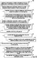
- a flow diagram of a method 400 for maintaining a gas turbine engine installed on an aircraft in accordance with an exemplary aspect of the present disclosure is provided.
- the method 400 may generally be used with a gas turbine engine in accordance with one or more the exemplary embodiments described above. Accordingly, it will be appreciated that the gas turbine engine generally includes an electric machine mounted at least partially inward of a core air flowpath of the gas turbine engine.
- the exemplary aspect of the method 400 depicted generally includes at (402) removing a cover assembly to expose a rotor mount of the gas turbine engine, a stator mount of the gas turbine engine, or both. More specifically, for the exemplary aspect depicted the cover assembly includes an aft cone and a cavity wall. Accordingly, removing the cover assembly at (402) may include removing both the aft cone and the cavity wall.
- the method 400 includes at (404) removing a rotor mount connecting a rotor of the electric machine to a rotary component of the gas turbine engine.
- removing the rotor mount at (404) includes at (406) removing a mechanical connector connecting a shaft extension member to the rotor of the electric machine and at (408) moving the shaft extension member at least partially along an axial direction of the gas turbine engine to decouple the shaft extension member from the rotary component of the gas turbine engine at a splined connection.
- the moving the shaft extension member at least partially along the axial direction at (408) may include sliding the shaft extension member at least partially along the axial direction.
- removing the mechanical connector connecting the shaft extension member to the rotor at (406) may include removing one or more bolts, screws, clamps, etc.
- the shaft extension member may be removed in any other suitable manner.
- removing the rotor mount at (404) may include removing one or more mechanical connectors coupling the shaft extension member to the rotary component.
- the rotor of the electric machine may not be coupled to the rotary component through a shaft extension member, and instead may be coupled in any other suitable manner.
- the method 400 further includes at (410) removing a stator mount connecting a stator of the electric machine to a stationary component of the gas turbine engine.
- removing the stator mount at (410) includes at (412) removing a mechanical connector connecting the stator of the electric machine to an electric machine mount, the electric machine mount coupled to or formed integrally with the stationary component of the gas turbine engine.
- removing the mechanical connector connecting the electric machine mount to the stator of the electric machine at (412) may include removing one or more bolts, screws, clamps, etc.
- the exemplary aspect depicted in Fig. 10 includes at (414) removing in situ the electric machine.
- the exemplary aspect described herein allows for the electric machine to be removed in situ, such that the gas turbine engine need not be removed from the aircraft with which it is installed, and does not need to be substantially disassembled.
- the electric machine may be removed at (414) with the only required disassembly being the removal of the cover assembly at (402), the removal of the rotor mount at (404) and the removal of the stator mount at (410).
- removing in situ the electric machine at (414) further includes at (416) disconnecting the electric machine from the electric communication bus. More specifically, for the exemplary aspect depicted, disconnecting the electric machine from the electric communication bus at (416) includes at (418) electrically disconnecting the electric machine from the electric communication bus at a quick release electric connection. In such a manner, the electric machine may be essentially automatically electrically disconnected through the removal of the electric machine without use of any tools.
- the electric connection may not be a quick release electric connection.
- the exemplary aspect of the method 400 depicted in Fig. 10 includes at (420) installing in situ a second electric machine in place of the first electric machine.
- installing in situ the second electric machine at (420) includes at (422) connecting a rotor of the second electric machine to the rotary component of the gas turbine engine using the rotor mount, at (424) connecting the stator of the second electric machine to the stationary component of the gas turbine engine using the stator mount, and at (426) installing the cover assembly to cover the rotor mount, the stator mount, or both.
- the gas turbine engine extends between a forward end and an aft end, and the electric machine is positioned at the aft end of the gas turbine engine.
- the electric machine itself defines an aft end and the rotor mount, the stator mount, or both, are positioned proximate the aft end of the electric machine (i.e., position closer to the aft end than a forward end).
- any other suitable configuration may be provided.
- the electric machine may be positioned within a nose cone (e.g., within the rotatable front hub 236/ spinner of the engine).
- the stator of the electric machine may be mounted to a stationary component of the engine through a suitable gearing, off a static carrier of a planetary gearbox (e.g., gearbox 234), or in any other suitable manner.
Landscapes
- Engineering & Computer Science (AREA)
- Mechanical Engineering (AREA)
- General Engineering & Computer Science (AREA)
- Chemical & Material Sciences (AREA)
- Combustion & Propulsion (AREA)
- Aviation & Aerospace Engineering (AREA)
- Manufacturing & Machinery (AREA)
- Transportation (AREA)
- Connection Of Motors, Electrical Generators, Mechanical Devices, And The Like (AREA)
- Structures Of Non-Positive Displacement Pumps (AREA)
Abstract
Description
- The present subject matter relates generally to a gas turbine engine having an embedded electric machine, and to a propulsion system for an aeronautical device including the same.
- Typical aircraft propulsion systems include one or more gas turbine engines. For certain propulsion systems, the gas turbine engines generally include a fan and a core arranged in flow communication with one another. Additionally, the core of the gas turbine engine general includes, in serial flow order, a compressor section, a combustion section, a turbine section, and an exhaust section. In operation, air is provided from the fan to an inlet of the compressor section where one or more axial compressors progressively compress the air until it reaches the combustion section. Fuel is mixed with the compressed air and burned within the combustion section to provide combustion gases. The combustion gases are routed from the combustion section to the turbine section. The flow of combustion gasses through the turbine section drives the turbine section and is then routed through the exhaust section, e.g., to atmosphere.
- For certain aircraft, it may be beneficial for the propulsion system to include an electric fan to supplement propulsive power provided by the one or more gas turbine engines included with the propulsion system. However, providing the aircraft with a sufficient amount of energy storage devices to power the electric fan may be space and weight prohibitive. Notably, certain gas turbine engines may include auxiliary generators positioned, e.g., within a cowling of the gas turbine engine. However, these auxiliary generators may not be configured to provide a sufficient amount of electrical power to adequately drive the electric fan.
- Accordingly, a propulsion system for an aircraft including one or more electric machines embedded within the gas turbine engine would be useful. Notably, however, the inventors of the present disclosure have discovered that a useful life span of typical electric machines is less than that of a gas turbine engine. Accordingly, the electric machines embedded within the gas turbine engines may need to be repaired or replaced more frequently than the gas turbine engines themselves. However, in order to replace an embedded electric machine, the gas turbine engine must be taken off wing and disassembled to expose the electric machine and install a new electric machine. Such a set up may be timely and cost inefficient. Therefore, an improved gas turbine engine with an embedded electric machine would be useful, and a propulsion system including the same would also be beneficial.
- Aspects and advantages of the invention will be set forth in part in the following description, or may be obvious from the description, or may be learned through practice of the invention.
- In one exemplary aspect of the present disclosure, a method is provided for maintaining a gas turbine engine installed on an aircraft, the gas turbine engine including an electric machine mounted at least partially inward of a core air flowpath of the gas turbine engine. The method includes removing a rotor mount connecting a rotor of the electric machine to a rotary component of the gas turbine engine; removing a stator mount connecting a stator of the electric machine to a stationary component of the gas turbine engine; and removing in situ the electric machine.
- For example, in certain exemplary aspects the method further includes removing a cover assembly to expose the rotor mount, the stator mount, or both.
- For example, in certain exemplary aspects the cover assembly includes an aft cone and a cavity wall.
- In certain exemplary aspects removing the rotor mount includes removing a mechanical connector connecting a shaft extension member to the rotor of the electric machine.
- For example, in certain exemplary aspects removing the rotor mount further includes moving the shaft extension member at least partially along an axial direction of the gas turbine engine to decouple the shaft extension member from the rotary component of the gas turbine engine at a splined connection.
- In certain exemplary aspects removing in situ the electric machine includes disconnecting the electric machine from an electric communication bus.
- For example, in certain exemplary aspects disconnecting the electric machine from the electric communication bus includes electrically disconnecting the electric machine from the electric communication bus at a quick release electric connection.
- In certain exemplary aspects the gas turbine engine extends between a forward end and an aft end, and wherein the electric machine is positioned at the aft end of the gas turbine engine.
- For example, in certain exemplary aspects the electric machine defines an aft end, and wherein the rotor mount, the stator mount, or both are positioned proximate the aft end of the electric machine.
- In certain exemplary aspects the electric machine is a first electric machine, and wherein the method further includes installing in situ a second electric machine in place of the first electric machine.
- For example, in certain exemplary aspects the method further includes connecting a rotor of the second electric machine to the rotary component of the gas turbine engine using the rotor mount; and connecting a stator of the second electric machine to the stationary component of the gas turbine engine using the stator mount.
- In an exemplary embodiment of the present disclosure, a gas turbine engine defining a radial direction and an axial direction is provided. The gas turbine engine includes a turbomachine including a compressor, a turbine, a rotary component rotatable with the compressor and the turbine, and a stationary component, the compressor and turbine together defining at least in part a core air flowpath; an electric machine positioned at least partially inward of the core air flowpath along the radial direction, the electric machine including a rotor and a stator; a rotor mount removably coupling the rotor of the electric machine to the rotary component; a stator mount removably coupling the stator of the electric machine to the stationary component; and a cover assembly removably positioned over the electric machine, the electric machine and cover assembly positioned such that the electric machine is removable from the gas turbine engine in situ when the cover assembly is removed.
- In certain exemplary embodiments the cover assembly includes an aft cone and a cavity wall.
- In certain exemplary embodiments the cover assembly consists essentially of an aft cone and a cavity wall.
- In certain exemplary embodiments the gas turbine engine further includes an electric communication bus; and a quick electric connection, the electric machine electrically connected to the electric communication bus through the quick electric connection.
- In certain exemplary embodiments the gas turbine engine defines an aft end, and wherein the electric machine is positioned proximate the aft end.
- In certain exemplary embodiments at least a portion of the cover assembly is visible from an outside of the gas turbine engine.
- In certain exemplary embodiments the gas turbine engine further includes an electric machine mount coupled to, or formed integrally with, the stationary component of the turbomachine, and wherein the electric machine is slidably received on the electric machine mount.
- In certain exemplary embodiments the stator mount fixedly couples the electric machine to the electric machine mount.
- In certain exemplary embodiments the gas turbine engine further includes a shaft extension member extending between a first end and a second end, wherein the first end is coupled to the rotary component of the turbomachine through a splined connection, and wherein the second end is coupled to the rotor of the electric machine by the rotor mount.
- These and other features, aspects and advantages of the present invention will become better understood with reference to the following description and appended claims. The accompanying drawings, which are incorporated in and constitute a part of this specification, illustrate embodiments of the invention and, together with the description, serve to explain the principles of the invention.
- A full and enabling disclosure of the present invention, including the best mode thereof, directed to one of ordinary skill in the art, is set forth in the specification, which makes reference to the appended figures, in which:
-
Fig. 1 is a top view of an aircraft according to various exemplary embodiments of the present disclosure. -
Fig. 2 is a port side view of the exemplary aircraft ofFig. 1 -
Fig. 3 is a schematic, cross-sectional view of a gas turbine engine in accordance with an exemplary aspect of the present disclosure. -
Fig. 4 is a schematic, cross-sectional view of an electric machine embedded in a gas turbine engine in accordance with an exemplary embodiment of the present disclosure. -
Fig. 5 is a schematic, cross-sectional view of an electric machine embedded in the exemplary gas turbine engine ofFig. 4 partially disassembled. -
Fig. 6 is another schematic, cross-sectional view of an electric machine embedded in the exemplary gas turbine engine ofFig. 4 partially disassembled -
Fig. 7 is a schematic, close up view of a stator mount and quick electrical connection in accordance with an exemplary embodiment of the present disclosure. -
Fig. 8 is another schematic view of the exemplary quick electric electrical connection ofFig. 7 . -
Fig. 9 is a schematic, close up view of a stator support and electric machine mount having alignment features in accordance with an exemplary embodiment of the present disclosure. -
Fig. 10 is a flow diagram of a method for maintaining a gas turbine engine in accordance with an exemplary aspect of the present disclosure. - Reference will now be made in detail to present embodiments of the invention, one or more examples of which are illustrated in the accompanying drawings. The detailed description uses numerical and letter designations to refer to features in the drawings. Like or similar designations in the drawings and description have been used to refer to like or similar parts of the invention.
- As used herein, the terms "first", "second", and "third" may be used interchangeably to distinguish one component from another and are not intended to signify location or importance of the individual components.
- The terms "forward" and "aft" refer to relative positions within a gas turbine engine or vehicle, and refer to the normal operational attitude of the gas turbine engine or vehicle. For example, with regard to a gas turbine engine, forward refers to a position closer to an engine inlet and aft refers to a position closer to an engine nozzle or exhaust.
- The terms "upstream" and "downstream" refer to the relative direction with respect to fluid flow in a fluid pathway. For example, "upstream" refers to the direction from which the fluid flows, and "downstream" refers to the direction to which the fluid flows.
- The terms "coupled," "fixed," "attached to," and the like refer to both direct coupling, fixing, or attaching, as well as indirect coupling, fixing, or attaching through one or more intermediate components or features, unless otherwise specified herein.
- The singular forms "a", "an", and "the" include plural references unless the context clearly dictates otherwise.
- Approximating language, as used herein throughout the specification and claims, is applied to modify any quantitative representation that could permissibly vary without resulting in a change in the basic function to which it is related. Accordingly, a value modified by a term or terms, such as "about", "approximately", and "substantially", are not to be limited to the precise value specified. In at least some instances, the approximating language may correspond to the precision of an instrument for measuring the value, or the precision of the methods or machines for constructing or manufacturing the components and/or systems. For example, the approximating language may refer to being within a 10 percent margin.
- Here and throughout the specification and claims, range limitations are combined and interchanged, such ranges are identified and include all the sub-ranges contained therein unless context or language indicates otherwise. For example, all ranges disclosed herein are inclusive of the endpoints, and the endpoints are independently combinable with each other.
- Referring now to the drawings, wherein identical numerals indicate the same elements throughout the figures,
Fig. 1 provides a top view of anexemplary aircraft 10 as may incorporate various embodiments of the present invention.Fig. 2 provides a port side view of theaircraft 10 as illustrated inFig. 1 . As shown inFigs. 1 and 2 collectively, theaircraft 10 defines alongitudinal centerline 14 that extends therethrough, a vertical direction V, a lateral direction L, aforward end 16, and anaft end 18. Moreover, theaircraft 10 defines amean line 15 extending between theforward end 16 andaft end 18 of theaircraft 10. As used herein, the "mean line" refers to a midpoint line extending along a length of theaircraft 10, not taking into account the appendages of the aircraft 10 (such as thewings 20 and stabilizers discussed below). - Moreover, the
aircraft 10 includes afuselage 12, extending longitudinally from theforward end 16 of theaircraft 10 towards theaft end 18 of theaircraft 10, and a pair ofwings 20. As used herein, the term "fuselage" generally includes all of the body of theaircraft 10, such as an empennage of theaircraft 10. The first ofsuch wings 20 extends laterally outwardly with respect to thelongitudinal centerline 14 from aport side 22 of thefuselage 12 and the second ofsuch wings 20 extends laterally outwardly with respect to thelongitudinal centerline 14 from astarboard side 24 of thefuselage 12. Each of thewings 20 for the exemplary embodiment depicted includes one or more leading edge flaps 26 and one or more trailing edge flaps 28. Theaircraft 10 further includes avertical stabilizer 30 having arudder flap 32 for yaw control, and a pair ofhorizontal stabilizers 34, each having anelevator flap 36 for pitch control. Thefuselage 12 additionally includes an outer surface orskin 38. It should be appreciated however, that in other exemplary embodiments of the present disclosure, theaircraft 10 may additionally or alternatively include any other suitable configuration of stabilizer that may or may not extend directly along the vertical direction V or horizontal/ lateral direction L. - The
exemplary aircraft 10 ofFigs. 1 and 2 includes apropulsion system 100, herein referred to as "system 100". Theexemplary system 100 includes one or more aircraft engines and one or more electric propulsion engines. For example, the embodiment depicted includes a plurality of aircraft engines, each configured to be mounted to theaircraft 10, such as to one of the pair ofwings 20, and an electric propulsion engine. More specifically, for the embodiment depicted, the aircraft engines are configured as gas turbine engines, or rather asturbofan jet engines wings 20 in an under-wing configuration. Additionally, the electric propulsion engine is configured to be mounted at the aft end of theaircraft 10, and hence the electric propulsion engine depicted may be referred to as an "aft engine." Further, the electric propulsion engine depicted is configured to ingest and consume air forming a boundary layer over thefuselage 12 of theaircraft 10. Accordingly, the exemplary aft engine depicted may be referred to as a boundary layer ingestion (BLI)fan 106. TheBLI fan 106 is mounted to theaircraft 10 at a location aft of thewings 20 and/or thejet engines BLI fan 106 is fixedly connected to thefuselage 12 at theaft end 18, such that theBLI fan 106 is incorporated into or blended with a tail section at theaft end 18, and such that themean line 15 extends therethrough. It should be appreciated, however, that in other embodiments the electric propulsion engine may be configured in any other suitable manner, and may not necessarily be configured as an aft fan or as a BLI fan. - Referring still to the embodiment of
Figs. 1 and 2 , in certain embodiments the propulsion system further includes one or moreelectric generators 108 operable with thejet engines jet engines electric generators 108. Although depicted schematically outside therespective jet engines electric generators 108 may be positioned within arespective jet engine electric generators 108 may be configured to convert the mechanical power to electrical power. For the embodiment depicted, thepropulsion system 100 includes anelectric generator 108 for eachjet engine power conditioner 109 and anenergy storage device 110. Theelectric generators 108 may send electrical power to thepower conditioner 109, which may transform the electrical energy to a proper form and either store the energy in theenergy storage device 110 or send the electrical energy to theBLI fan 106. For the embodiment depicted, theelectric generators 108,power conditioner 109,energy storage device 110, andBLI fan 106 are all are connected to an electric communication bus 111, such that theelectric generator 108 may be in electrical communication with theBLI fan 106 and/or theenergy storage device 110, and such that theelectric generator 108 may provide electrical power to one or both of theenergy storage device 110 or theBLI fan 106. Accordingly, in such an embodiment, thepropulsion system 100 may be referred to as a gas-electric propulsion system. - It should be appreciated, however, that the
aircraft 10 andpropulsion system 100 depicted inFigs. 1 and 2 is provided by way of example only and that in other exemplary embodiments of the present disclosure, any othersuitable aircraft 10 may be provided having any othersuitable propulsion system 100 configured in any other suitable manner. For example, it should be appreciated that in various other embodiments, theBLI fan 106 may alternatively be positioned at any suitable location proximate theaft end 18 of theaircraft 10. Further, in still other embodiments the electric propulsion engine may not be positioned at the aft end of theaircraft 10, and thus may not be configured as an "aft engine." For example, in other embodiments, the electric propulsion engine may be incorporated into the fuselage of theaircraft 10, and thus configured as a "podded engine," or pod-installation engine. Further, in still other embodiments, the electric propulsion engine may be incorporated into a wing of theaircraft 10, and thus may be configured as a "blended wing engine." Moreover, in other embodiments, the electric propulsion engine may not be a boundary layer ingestion fan, and instead may be mounted at any suitable location on theaircraft 10 as a freestream injection fan. Furthermore, in still other embodiments, thepropulsion system 100 may not include, e.g., thepower conditioner 109 and/or theenergy storage device 110, and instead the generator(s) 108 may be directly electrically connected to theBLI fan 106. - Referring now to
Fig. 3 , a schematic cross-sectional view of a propulsion engine in accordance with an exemplary embodiment of the present disclosure is provided. In certain exemplary embodiments, the propulsion engine may be configured a high-bypassturbofan jet engine 200, herein referred to as "turbofan 200." Notably, in at least certain embodiments, thejet engines turbofan 200 may be representative ofjet engines turbofan 200 may be incorporated into any othersuitable aircraft 10 orpropulsion system 100. - As shown in
Fig. 3 , theturbofan 200 defines an axial direction A (extending parallel to alongitudinal centerline 201 provided for reference), a radial direction R, and a circumferential direction C (extending about the axial direction A; not depicted inFig. 3 ). In general, theturbofan 200 includes afan section 202 and aturbomachine 204 disposed downstream from thefan section 202. - The
exemplary turbomachine 204 depicted generally includes a substantially tubularouter casing 206 that defines anannular inlet 208. Theouter casing 206 encases, in serial flow relationship, a compressor section including a booster or low pressure (LP)compressor 210 and a high pressure (HP)compressor 212; acombustion section 214; a turbine section including a high pressure (HP)turbine 216 and a low pressure (LP)turbine 218; and a jetexhaust nozzle section 220. The compressor section,combustion section 214, and turbine section together define acore air flowpath 221 extending from theannular inlet 208 through theLP compressor 210,HP compressor 212,combustion section 214,HP turbine section 216,LP turbine section 218 and jetnozzle exhaust section 220. A high pressure (HP) shaft orspool 222 drivingly connects theHP turbine 216 to theHP compressor 212. A low pressure (LP) shaft orspool 224 drivingly connects theLP turbine 218 to theLP compressor 210. - For the embodiment depicted, the
fan section 202 includes avariable pitch fan 226 having a plurality offan blades 228 coupled to adisk 230 in a spaced apart manner. As depicted, thefan blades 228 extend outwardly fromdisk 230 generally along the radial direction R. Eachfan blade 228 is rotatable relative to thedisk 230 about a pitch axis P by virtue of thefan blades 228 being operatively coupled to asuitable actuation member 232 configured to collectively vary the pitch of thefan blades 228 in unison. Thefan blades 228,disk 230, andactuation member 232 are together rotatable about thelongitudinal axis 12 byLP shaft 224 across apower gear box 234. Thepower gear box 234 includes a plurality of gears for stepping down the rotational speed of theLP shaft 224 to a more efficient rotational fan speed. - Referring still to the exemplary embodiment of
Fig. 3 , thedisk 230 is covered by rotatablefront hub 236 aerodynamically contoured to promote an airflow through the plurality offan blades 228. Additionally, theexemplary fan section 202 includes an annular fan casing orouter nacelle 238 that circumferentially surrounds thefan 226 and/or at least a portion of theturbomachine 204. Thenacelle 238 is supported relative to theturbomachine 204 by a plurality of circumferentially-spaced outlet guide vanes 240. Adownstream section 242 of thenacelle 238 extends over an outer portion of theturbomachine 204 so as to define abypass airflow passage 244 therebetween. - Additionally, the
exemplary turbofan 200 depicted includes anelectric machine 246 rotatable with thefan 226. Specifically, for the embodiment depicted, theelectric machine 246 is configured as an electric generator co-axially mounted to and rotatable with the LP shaft 224 (theLP shaft 224 also rotating thefan 226 through, for the embodiment depicted, the power gearbox 234). As used herein, "co-axially" refers to the axes being aligned. It should be appreciated, however, that in other embodiments, an axis of theelectric machine 246 may be offset radially from the axis of theLP shaft 224 and further may be oblique to the axis of theLP shaft 224, such that theelectric machine 246 may be positioned at any suitable location at least partially inward of thecore air flowpath 221. - The
electric machine 246 includes arotor 248 and astator 250. In certain exemplary embodiments, therotor 248 andstator 250 of theelectric machine 246 are configured in substantially the same manner as the exemplary rotor and stator of the electric machine described below. Notably, when theturbofan engine 200 is integrated into thepropulsion system 100 described above with reference toFigs. 1 and 2 , theelectric generators 108 may be configured in substantially the same manner as theelectric machine 246 ofFig. 3 . - Further, for the embodiment depicted, the gas turbine engine, or rather, the
turbofan engine 200, additionally includes acover assembly 251 removably positioned over theelectric machine 246. Theelectric machine 246 and coverassembly 251 are positioned such that theelectric machine 246 is removable from the gas turbine engine (i.e., the turbofan engine 200) in situ when thecover assembly 251 is removed. It will be appreciated, that as used herein, the term "in situ," with reference to a particular task or operation, refers to such task or operation being completed with the engine still installed on or in the aircraft. - It should be also appreciated, however, that the
exemplary turbofan engine 200 depicted inFig. 3 is provided by way of example only, and that in other exemplary embodiments, theturbofan engine 200 may have any other suitable configuration. For example, in other exemplary embodiments, theturbofan engine 200 may be configured as a turboprop engine, a turbojet engine, a differently configured turbofan engine (e.g., direct drive engine, fixed-pitch engine, etc.), or any other suitable gas turbine engine. - Referring now to
Fig. 4 , anelectric machine 246 embedded within a gas turbine engine in accordance with an exemplary embodiment of the present disclosure is depicted. More particularly, for the embodiment depicted, theelectric machine 246 is embedded within a turbine section of the gas turbine engine, at a location inward of acore air flowpath 221 of the gas turbine engine. Additionally, theelectric machine 246 is positioned at least partially within or aft of the turbine section along an axial direction A. In certain exemplary embodiments, theelectric machine 246 and gas turbine engine depicted inFig. 4 may be configured in substantially the same manner as the exemplaryelectric machine 246 andturbofan engine 200 described above with reference toFig. 3 . Accordingly, the same or similar numbers may refer to the same or similar parts. - Moreover, it will be appreciated that the gas turbine engine generally includes a rotary component and a stationary component. The rotary component is rotatable with a compressor within a compressor section (not shown) of the gas turbine engine and a turbine within the turbine section of the gas turbine engine. By contrast, the stationary component may be any suitable component which is configured to remain stationary relative to the various rotating components of the compressors and turbines.
- As with the embodiment above, the
electric machine 246 generally includes arotor 248 and astator 250. Therotor 248 of theelectric machine 246 is coupled to the rotary component of the gas turbine engine and thestator 250 of theelectric machine 246 is coupled to the stationary component of the gas turbine engine. More particularly, for the embodiment depicted the rotary component to which therotor 248 of theelectric machine 246 is coupled is anLP shaft 224 of the gas turbine engine, such that therotor 248 is rotatable with theLP shaft 224. By contrast, the stationary component to which thestator 250 of theelectric machine 246 is coupled is astructural support member 256 of the turbine section. The connection between therotor 248 of theelectric machine 246 and the rotary component of the gas turbine engine, as well as thestator 250 of theelectric machine 246 to the stationary component of the gas turbine engine will be described in greater detail below. - Referring still to the exemplary
electric machine 246 ofFig. 4 , thestructural support member 256 is configured as part of an aft frame assembly and extends from anaft frame strut 258 of the aft frame assembly of the gas turbine engine. Theaft strut 258 extends through thecore air flowpath 221 of the gas turbine engine, and is configured to provide structural support for the gas turbine engine. Thestructural support member 256 also extends forward to support an aft engine bearing 260-the aft engine bearing 260 rotatably supporting an aft end of theLP shaft 224. - Further, the gas turbine engine defines an
electric machine sump 262. Theelectric machine sump 262 extends from a location forward of theelectric machine 246 continuously to a location aft of theelectric machine 246. Moreover, the gas turbine engine depicted includes an electricmachine lubrication system 264, with the electricmachine lubrication system 264 in fluid communication with theelectric machine sump 262, for providing a thermal fluid to theelectric machine sump 262. For the embodiment depicted, the electricmachine lubrication system 264 may operate independently of a gas turbine engine lubrication system. - In order to further maintain a temperature of the
electric machine 246, the cooling system of the exemplary gas turbine engine depicted further includes abuffer cavity 266 surrounding at least a portion of theelectric machine 246. Thebuffer cavity 266 may further thermally insulate theelectric machine 246. Thebuffer cavity 266, for the embodiment depicted, extends continuously from a location forward of theelectric machine 246 to a location aft of theelectric machine 246 along the axial direction A. Thebuffer cavity 266 may act as an insulator from relatively hot operating temperatures within thecore air flowpath 221 extending through the turbine section of the gas turbine engine. - Furthermore, for the embodiment depicted, the gas turbine engine includes a cooling
duct 268. The coolingduct 268 is in airflow communication with thebuffer cavity 266 for providing a cooling airflow to thebuffer cavity 266. For example, in the embodiment depicted, the coolingduct 268 defines an outlet (not labeled) extending through thestructural support member 256 for providing the cooling airflow from the coolingduct 268 through thestructural support member 256 and into thebuffer cavity 266. The coolingduct 268 may also be in airflow communication with a relatively cool air source for providing the cooling airflow. In certain exemplary embodiments, the cool air source may be a compressor section of the gas turbine engine (wherein the cooling airflow may be diverted from the compressor section), or a fan of the gas turbine engine (wherein the cooling airflow may be diverted from the fan). - It will be appreciated that the electric
machine lubrication system 264, coolingduct 268, andbuffer cavity 266 are each configured as part of the cooling system for maintaining at least certain components of theelectric machine 246 within a desired temperature range. For example, when one or more permanent magnets are included with theelectric machine 246, the cooling system may maintain such components below a Curie temperature limit for the plurality of permanent magnets, or below a predetermined buffer of the Curie temperature limit. - Referring still to the embodiment of
Fig. 4 , as briefly discussed above during operation of the gas turbine engine, theLP shaft 224 may rotate therotor 248 of theelectric machine 246, allowingelectric machine 246 to function as an electric generator producing electrical power. Additionally, theelectric machine 246 is in electrical communication with-i.e. electrically connected to-anelectric communication bus 270. Theelectric communication bus 270 is electrically connected to theelectric machine 246 at a location radially inward of thecore air flowpath 221. - Specifically, for the embodiment depicted, the
electric communication bus 270 includes a firstelectrical connection 272, which as will be described in greater detail below may be a quick electrical connection. More specifically, the firstelectrical connection 272 receives anelectrical line 274 from the electric machine 246 (for the embodiment depicted, from thestator 250 of the electric machine 246) and connects theelectric line 274 to anintermediate section 276 of theelectric communication bus 270. Theintermediate section 276 extends through thecore air flowpath 221 to a secondelectrical connection 278 mounted at a location radially outward of thecore air flowpath 221, e.g., within a cowling of the gas turbine engine. The secondelectrical connection 278 connects theintermediate section 276 of theelectric communication bus 270 to anoutlet line 280 of theelectric communication bus 270 for connection to one or more systems of the gas turbine engine and/or aircraft with which the gas turbine engine is installed. - As stated and depicted in
Fig. 4 , at least a portion of theelectric communication bus 270 extends through thecore air flowpath 221. More specifically, for the embodiment depicted, theintermediate section 276 of theelectric communication bus 270 extends through thecore air flowpath 221 at a location downstream of a combustion section of the gas turbine engine (such as thecombustion section 214 of theexemplary turbofan engine 200 ofFig. 3 ). In particular, theintermediate section 276 extends through/is positioned within theaft strut 258. - It should be appreciated, however, that in other exemplary embodiments, the
electric communication bus 270 may have any other suitable configuration for transferring electrical power from theelectric machine 246 located radially inward from thecore air flowpath 221 to a location radially outward of thecore air flowpath 221. - Referring particularly to the exemplary
electric machine 246 depicted, for the embodiment shown, and as stated, theelectric machine 246 generally includes arotor 248 and astator 250. Therotor 248 includes arotor support 282 and, for the embodiment depicted, a plurality ofrotor magnets 284. Thestator 250 similarly includes astator support 286 and, for the embodiment depicted, a plurality ofcoils 288. Of course, in other embodiments of theelectric machine 246, therotor 248 andstator 250 may have any other suitable configuration for, e.g., converting rotational power from the rotary component of the gas turbine engine to electrical power. - As is depicted, the exemplary
electric machine 246 further includes aforward bearing 290 located forward of therotor magnets 284 andstator coils 288 and anaft bearing 292 located aft of therotor magnets 284 and stator coils 288. Theforward bearing 290 andaft bearing 292 are each configured to rotatably support therotor support 282 relative to thestator support 286. For the embodiment depicted, theforward bearing 290 is configured as a single roller bearing and theaft bearing 292 is configured as a single ball bearing. However, in other embodiments, any other suitable type of bearing and/or combination of bearings may be provided for theforward bearing 290 and/or theaft bearing 292. Additionally, in other embodiments, theelectric machine 246 may have any other suitable bearing configuration. - As also noted above, the
rotor 248 of theelectric machine 246 is coupled to the rotary component of the gas turbine engine (or rather of a turbomachine of the gas turbine engine; seeFig. 3 ) and thestator 250 of theelectric machine 246 is coupled to the stationary component of the gas turbine engine (or rather of the turbomachine of the gas turbine engine). For the embodiment depicted, the gas turbine engine further includes arotor mount 294 removably coupling therotor 248 of theelectric machine 246 to the rotary component and astator mount 295 removably coupling thestator 250 of theelectric machine 246 to the stationary component. - More specifically, for the embodiment depicted, the gas turbine engine further includes a
shaft extension member 296 extending between afirst end 298 and asecond end 300. As noted, for the embodiment depicted, the rotary component is theLP shaft 224 of the gas turbine engine. Thefirst end 298 of theshaft extension member 296 is coupled to theLP shaft 224 of the gas turbine engine through asplined connection 302. In such a manner, it will be appreciated that thefirst end 298 of theshaft extension member 296 may be moveably/ slidably received onto the LP shaft 224 (i.e., slidable along the axial direction A), and fixed along a circumferential direction (i.e., such that thefirst end 298 of theshaft extension member 296 is not movable relative to theLP shaft 224 along the circumferential direction; the circumferential direction being a direction extending about the axial direction A). - Further, the
second end 300 of theshaft extension member 296 is coupled to therotor 248 of theelectric machine 246 by therotor mount 294, and more specifically, is coupled to therotor support 282 of theelectric machine 246 by therotor mount 294. For the embodiment depicted, therotor mount 294 is a mechanical coupling joining therotor support 282 with thesecond end 300 of theshaft extension member 296. More specifically, for the embodiment depicted, therotor mount 294 is a bolt extending at least partially through therotor support 282 and thesecond end 300 of theshaft extension member 296, and more specifically still, is a plurality of bolts spaced along the circumferential direction, with each bolt extending at least partially through therotor support 282 and thesecond end 300 of theshaft extension member 296. - It will be appreciated, however, that in other exemplary embodiments, any other
suitable rotor mount 294 may be utilized. For example, in other embodiments, therotor mount 294 may be one or more screws, one or more clips, one or more clamps, corresponding features on thesecond end 300 of theshaft extension member 296 and therotor support 282, etc. Additionally, although for the embodiment depicted, thefirst end 298 of theshaft extension member 296 is coupled with theLP shaft 224 through thesplined connection 302, in other embodiments, theshaft extension member 296 may be coupled to theLP shaft 224 in a fixed manner along the axial direction A in any suitable manner. However, by utilizing thesplined connection 302 between theshaft extension member 296 and theLP shaft 224, a removeability of such component is increased, as will be discussed below. For example, in other exemplary embodiments, theshaft extension member 296, or other mounting structure not shown, may be configured to facilitate an "off-axis" mounting of theelectric machine 246. For example, theshaft extension member 292 may be coupled to a bevel gear assembly, a compound gear set, etc. allowing theelectric machine 246 to rotate about an axis different than theaxis 201 of the gas turbine engine (as is the case with the embodiment depicted). In such a case, theelectric machine 246 may rotate about an axis offset, but parallel to, theaxis 201 of the gas turbine engine, or may rotate about an axis defining an angle between, e.g., 0 and ninety degrees with theaxis 201 of the gas turbine engine. - Furthermore for the embodiment depicted in
Fig. 4 , the gas turbine engine further includes anelectric machine mount 304 coupled to, or formed integrally with, the stationary component of the gas turbine engine (or rather of the turbomachine of the gas turbine engine). More specifically, theelectric machine mount 304 is fixedly coupled to the stationary component of the gas turbine engine, and more specifically still, is fixedly coupled to thestructural support member 256 of the gas turbine engine. - The
electric machine mount 304, for the embodiment depicted, includes at least a portion extending generally along the axial direction A of the gas turbine engine. As will be appreciated more fully from the discussion of the Figs. below, for the embodiment shown, theelectric machine 246 is slidably received on theelectric machine mount 304, and thestator mount 295 fixedly couples theelectric machine 246 to theelectric machine mount 304. More specifically, for the embodiment depicted, thestator support 286 of theelectric machine 246 is slidably received, along the axial direction A of the gas turbine engine, on theelectric machine mount 304 and thestator mount 295 fixedly couples thestator support 286 of thestator 250 to theelectric machine mount 304. - Similar to the
rotor mount 294, for the embodiment depicted, thestator mount 295 is configured as a mechanical coupling joining thestator support 286 with theelectric machine mount 304. More specifically, for the embodiment depicted, thestator mount 295 is a bolt extending at least partially through thestator support 286 and the electric machine mount 304 (or rather, respective flanges of thestator support 286 and the electric machine mount 304), and more specifically still, is a plurality of bolts spaced along the circumferential direction, with each bolt extending at least partially through thestator support 286 and theelectric machine mount 304. It will be appreciated, however, that in other exemplary embodiments, any othersuitable stator mount 295 may be utilized. For example, in other embodiments, thestator mount 295 may be one or more screws, one or more clips, one or more clamps, corresponding features on theelectric machine mount 304 and thestator support 286, etc. - Also for the embodiment depicted, the gas turbine engine further includes a
cover assembly 306 removably positioned over theelectric machine 246. As will be appreciated more fully from the discussion below, theelectric machine 246 and coverassembly 306 are positioned such that theelectric machine 246 is removable from the gas turbine engine in situ when thecover assembly 306 is removed. - For the embodiment depicted, the
cover assembly 306 generally includes anaft cone 308 and acavity wall 310. More specifically, for the embodiment depicted, thecover assembly 306 essentially only includes theaft cone 308 and thecavity wall 310. The term "aft cone" as used herein refers to any aerodynamic cowling positioned generally at the aft end of the engine. Thecavity wall 310 surrounds at least a portion of theelectric machine 246. More specifically, for the embodiment depicted, thecavity wall 310 is coupled to anextension member 312, with theextension member 312, in turn, coupled to thestructural support member 256. Thecavity wall 310 andextension member 312 together substantially completely define a radially outer bound theelectric machine sump 262. Notably, thecavity wall 310 is connected to theextension member 312 at a cavity wall joint using acavity wall mount 314. The cavity wall joint is located outward of theelectric machine 246 along the radial direction R. Additionally, thecavity wall mount 314 is, for the embodiment depicted, a mechanical coupling, and more specifically, is a bolt extending at least partially through a flange of thecavity wall 310 and a flange of theextension member 312. More specifically still, thecavity wall mount 314 is configured as a plurality of bolts spaced along the circumferential direction. However, as with therotor mount 294 andstator mount 295, in other embodiments, thecavity wall mount 314 may have any other suitable configuration for joining thecavity wall 310 to theextension member 312, or any other suitable stationary component of the gas turbine engine (or rather, of the turbomachine of the gas turbine engine). - Similarly, the
aft cone 308 also surrounds least a portion of theelectric machine 246. Theaft cone 308, for the embodiment depicted, defines at least in part thebuffer cavity 266 described above. Moreover, theaft cone 308 is, for the embodiment depicted, coupled to the stationary component of the gas turbine engine (or rather, of the turbomachine of the gas turbine engine), and more specifically, to thestructural support member 256. More specifically, still, theaft cone 308 is coupled to the structural support member through anaft cone mount 316 at an aft cone joint. The aft cone joint is located outward of theelectric machine 246 along the radial direction R, and further, for the embodiment depicted, is located outward of the cavity wall joint along the radial direction R. - Additionally, the
aft cone mount 316 is, for the embodiment depicted, a mechanical coupling, and more specifically, is a bolt extending at least partially through a flange of theaft cone 308 and a flange of thestructural support member 256. More specifically still, thecavity wall mount 314 is configured as a plurality of bolts spaced along the circumferential direction. However, as with therotor mount 294 andstator mount 295, in other embodiments, thecavity wall mount 314 may have any other suitable configuration for joining theaft cone 308 to thestructural support member 256, or any other suitable stationary component of the gas turbine engine (or rather, of the turbomachine of the gas turbine engine). - As will be appreciated from the present disclosure, for the embodiment shown, at least a portion of the
cover assembly 306 is visible from an outside of the gas turbine engine (see also, e.g.,Fig. 3 ). More specifically, substantially all of theaft cone 308 is visible from an outside of the gas turbine engine for the embodiment depicted. It will be appreciated, that as used herein, the term "visible form an outside" with respect to a component of a gas turbine engine, refers to such component defining a clear, straight line of sight to the outside of the gas turbine engine. In such a manner, theelectric machine 246 may be relatively easily replaced in the event theelectric machine 246 fails or otherwise deteriorates more rapidly than the gas turbine engine. - For example, referring now to
Fig. 5 , it will be appreciated that for the embodiment depicted, theelectric machine 246 may generally be removed from the gas turbine engine in situ generally by removing thecover assembly 306, therotor mount 294, andstator mount 295. More specifically, as is illustrated inFig. 5 , thecover assembly 306 may first be removed, and more specifically still, theaft cone mount 316 may be removed to remove theaft cone 308 and thecavity wall mount 314 may be removed to remove thecavity wall 310. With the removal of thecover assembly 306, and more specifically, of theaft cone 308 and thecavity wall 310, therotor mount 294 is exposed. Therotor mount 294 may be removed, allowing for theshaft extension member 296 to be removed. As noted above, thefirst end 298 of theshaft extension member 296 is coupled to the rotary components of the turbomachine through thesplined connection 302. In such a manner, theshaft extension member 296 may be relatively easily removed from the rotary component by sliding theshaft extension member 296 generally along the axial direction A. However, in other embodiments, theshaft extension member 296 may be coupled to the rotary component in any other suitable manner. - Referring now particularly to
Fig. 6 , with thecover assembly 306 removed and with therotor mount 294 andshaft extension member 296 removed, thestator mount 295 is exposed. Thestator mount 295 may then be removed and theelectric machine 246 may be slidably removed from theelectric machine mount 304. In such a manner, theelectric machine 246 may be relatively easily removed or uninstalled from the gas turbine engine in situ, such that the gas turbine engine may not need to be taken off wing (i.e., uninstalled from the aircraft) and substantially disassembled to expose theelectric machine 246 and repair or replace theelectric machine 246. With theelectric machine 246 removed, a new, secondelectric machine 246 may be installed in a reverse order than that discussed above. - It will be appreciated, that the exemplary
electric machine 246 depicted may be removed as a unit from the gas turbine engine. For example, therotor 248 andstator 250 may be removed together, with thestator support 286 androtor support 282 still coupled through thebearings electric machine 246 within the gas turbine engine, as thebearings - Notably, referring generally to
Figs. 4 through 6 , it will be appreciated that for the embodiment depicted, the firstelectrical connection 272, as noted above, is a quick electrical connection. In such a manner, theelectric machine 246 may be removed and electrically disconnected from theelectric communication bus 270 of the gas turbine engine without use of tools. For example, referring particularly toFig. 7 , a close-up, schematic view of thestator mount 295 coupling thestator support 286 to theelectric machine mount 304 and the firstelectrical connection 272 is provided. For the embodiment depicted, the firstelectrical connection 272 includes afirst member 318 coupled to or positioned within aflange 320 of theelectric machine mount 304 and asecond member 322 coupled to or positioned within aflange 324 of thestator support 286. When thestator mount 295 couples thestator support 286 to theelectric machine mount 304, thefirst member 318 andsecond member 322 of the firstelectrical connection 272 are positioned together to electrically connect theelectric line 274 of theelectric machine 246 to theelectric communication bus 270. Thefirst member 318 andsecond member 322 of the firstelectrical connection 272 may be electrically connected and electrically disconnected without use of any tools. For example, thefirst member 318 may be fixedly coupled to theflange 320 of theelectric machine mount 304 and thesecond member 322 may be fixedly coupled to theflange 322 of thestator support 286. In such a manner, the first andsecond members electric machine 246. Such may allow for an easier removal of theelectric machine 246 and/or installation of a newelectric machine 246. - For example, referring briefly to
Fig. 8 , a close-up view is provided of the firstelectrical connection 272 with thefirst member 318 electrically disconnected from thesecond member 322. As is depicted, in at least one exemplary embodiment, thefirst member 318 of the firstelectrical connection 272 may have aprong 326 and define anopening 328. Thesecond member 322 may similarly have aprong 330 and define anopening 332. Theprong 326 of thefirst member 318 may extend into theopening 332 of thesecond member 322, and similarly, theprong 330 of thesecond member 322 may extend into theopening 328 of thefirst member 318. However, in other embodiments, any other suitable configuration may be provided for quickly and/or relatively easily electrically connecting and/or disconnecting theelectric machine 246 to or from theelectric communication bus 270. - It will be appreciated, however, that in other exemplary embodiments, the first
electrical connection 272 may instead be configured in any other suitable manner. For example, in other embodiments, the firstelectrical connection 272 may be a more conventional electrical connection, may be a cooled electrical connection, may include anti-arcing structures/ features, etc. Such may be important for relatively high voltage systems. - Further, referring again generally to
Figs. 4 through 6 , it will be appreciated that in at least certain exemplary embodiments, the exemplary gas turbine engine may include one or more alignment features for ensuring theelectric machine 246 is properly aligned and oriented within the turbomachine. For example, in certain exemplary embodiments, one or more of thestator support 286 andelectric machine mount 304,shaft extension member 296 andLP shaft 224, etc. may include corresponding alignment features for ensuring theelectric machine 246 is properly aligned and oriented within the turbomachine. Specifically, for example, referring now briefly toFig. 9 , providing a view of astator support 286 and anelectric machine mount 304 in accordance with one embodiment of the present disclosure, aflange 320 of theelectric machine mount 304 andflange 324 of thestator support 286 may include one or more corresponding alignment features to ensure theelectric machine 246 is properly aligned and oriented (e.g., along a circumferential direction) within the turbomachine. For the embodiment shown, theflange 320 includes analignment pin 334 and theflange 324 includes analignment opening 336. When thepin 334 is received within the opening 336 (e.g., during assembly/ installation of the electric machine 246), theelectric machine 246 may be properly aligned and oriented within the turbomachine. For the embodiment shown, thepin 334 is an elongated pin 334 (defining a length greater than a thickness of theflange 324 along the axial direction A, such as up to 1,000 times greater than the thickness of the flange 324), such that thepin 334 andopening 336 may guide theelectric machine 246 along the axial direction A as it is installed, while ensuring proper circumferential positioning as well. Notably, however, in other embodiments, any other suitable alignment features may be provided (e.g., corresponding grooves or other features), and/or may be provided on any suitable components. - It should further be appreciated that the exemplary gas turbine engine, depicted in
Figures 4 through 9 , and more specifically, the exemplary turbomachine andelectric machine 246 depicted inFigs. 4 through 9 , is provided by way of example only. In other exemplary embodiments, the gas turbine engine, and one or more components thereof, may be formed in any other suitable manner. For example, although the exemplaryelectric machine 246 depicted is an outrunner electric machine 246 (i.e., with therotor magnets 284 positioned radially outward of the stator coils 288), in other exemplary embodiments, the configuration may be switched, such that theelectric machine 246 is configured as an inrunner electric machine 246 (i.e., with therotor magnets 284 positioned radially inward of the stator coils 288). Further, although theexemplary cover assembly 306 for the embodiment shown consists essentially of anaft cone 308 and acavity wall 310, in other embodiments, any other suitable components may be included with thecover assembly 306, or alternatively, thecover assembly 306 may not include each of the components depicted. For example, in other embodiments, one or both of theaft cone 308 and thecavity wall 310 of thecover assembly 306 may additionally include layers of insulation, additional buffer layers, additional cover plating, etc. Further, in certain embodiments, thecover assembly 306 may be integrated with other systems of theelectric machine 246 and/or gas turbine engine. For example, in other embodiment, thecover assembly 306 may be integrated with, e.g., a scavenge line of the electricmachine lubrication system 264, an outlet duct of thebuffer cavity 266, etc. - Referring now to
Fig. 10 , a flow diagram of amethod 400 for maintaining a gas turbine engine installed on an aircraft in accordance with an exemplary aspect of the present disclosure is provided. Themethod 400 may generally be used with a gas turbine engine in accordance with one or more the exemplary embodiments described above. Accordingly, it will be appreciated that the gas turbine engine generally includes an electric machine mounted at least partially inward of a core air flowpath of the gas turbine engine. - The exemplary aspect of the
method 400 depicted generally includes at (402) removing a cover assembly to expose a rotor mount of the gas turbine engine, a stator mount of the gas turbine engine, or both. More specifically, for the exemplary aspect depicted the cover assembly includes an aft cone and a cavity wall. Accordingly, removing the cover assembly at (402) may include removing both the aft cone and the cavity wall. - Additionally, the
method 400 includes at (404) removing a rotor mount connecting a rotor of the electric machine to a rotary component of the gas turbine engine. For the exemplary aspect depicted, removing the rotor mount at (404) includes at (406) removing a mechanical connector connecting a shaft extension member to the rotor of the electric machine and at (408) moving the shaft extension member at least partially along an axial direction of the gas turbine engine to decouple the shaft extension member from the rotary component of the gas turbine engine at a splined connection. For example, in certain exemplary aspects, the moving the shaft extension member at least partially along the axial direction at (408) may include sliding the shaft extension member at least partially along the axial direction. - As noted, in certain exemplary aspects, the
method 400 may be utilized with one or more of the exemplary gas turbine engines discussed above. Accordingly, in at least certain exemplary aspects, removing the mechanical connector connecting the shaft extension member to the rotor at (406) may include removing one or more bolts, screws, clamps, etc. Additionally, in other exemplary aspects, the shaft extension member may be removed in any other suitable manner. For example, in other embodiments, instead of sliding the shaft extension member at least partially along the axial direction to decouple the shaft extension member from the rotary component at (408), removing the rotor mount at (404) may include removing one or more mechanical connectors coupling the shaft extension member to the rotary component. Further, in still other exemplary aspects, the rotor of the electric machine may not be coupled to the rotary component through a shaft extension member, and instead may be coupled in any other suitable manner. - Referring still to the exemplary aspect depicted, the
method 400 further includes at (410) removing a stator mount connecting a stator of the electric machine to a stationary component of the gas turbine engine. For the example aspect depicted, removing the stator mount at (410) includes at (412) removing a mechanical connector connecting the stator of the electric machine to an electric machine mount, the electric machine mount coupled to or formed integrally with the stationary component of the gas turbine engine. Similar to the exemplary aspect discussed above, removing the mechanical connector connecting the electric machine mount to the stator of the electric machine at (412) may include removing one or more bolts, screws, clamps, etc. - Further, the exemplary aspect depicted in
Fig. 10 includes at (414) removing in situ the electric machine. It will be appreciated that the exemplary aspect described herein allows for the electric machine to be removed in situ, such that the gas turbine engine need not be removed from the aircraft with which it is installed, and does not need to be substantially disassembled. For example, in certain exemplary aspects, the electric machine may be removed at (414) with the only required disassembly being the removal of the cover assembly at (402), the removal of the rotor mount at (404) and the removal of the stator mount at (410). - Moreover, it will be appreciated that when installed, the electric machine is electrically coupled to the electric communication bus of the gas turbine engine and/or aircraft. Accordingly, as is depicted, removing in situ the electric machine at (414) further includes at (416) disconnecting the electric machine from the electric communication bus. More specifically, for the exemplary aspect depicted, disconnecting the electric machine from the electric communication bus at (416) includes at (418) electrically disconnecting the electric machine from the electric communication bus at a quick release electric connection. In such a manner, the electric machine may be essentially automatically electrically disconnected through the removal of the electric machine without use of any tools. However, in other exemplary aspects, as discussed above, the electric connection may not be a quick release electric connection.
- Further, with the electric machine removed, which hereinafter may be referred to as a first electric machine, the exemplary aspect of the
method 400 depicted inFig. 10 includes at (420) installing in situ a second electric machine in place of the first electric machine. For the exemplary aspect depicted, installing in situ the second electric machine at (420) includes at (422) connecting a rotor of the second electric machine to the rotary component of the gas turbine engine using the rotor mount, at (424) connecting the stator of the second electric machine to the stationary component of the gas turbine engine using the stator mount, and at (426) installing the cover assembly to cover the rotor mount, the stator mount, or both. - It will be appreciated that for the exemplary aspect depicted, the gas turbine engine extends between a forward end and an aft end, and the electric machine is positioned at the aft end of the gas turbine engine. Further, it will be appreciated that the electric machine itself defines an aft end and the rotor mount, the stator mount, or both, are positioned proximate the aft end of the electric machine (i.e., position closer to the aft end than a forward end). However, in other exemplary aspects, any other suitable configuration may be provided. For example, in other exemplary embodiments, the electric machine may be positioned within a nose cone (e.g., within the
rotatable front hub 236/ spinner of the engine). With such an embodiment, the stator of the electric machine may be mounted to a stationary component of the engine through a suitable gearing, off a static carrier of a planetary gearbox (e.g., gearbox 234), or in any other suitable manner. - This written description uses examples to disclose the invention, including the best mode, and also to enable any person skilled in the art to practice the invention, including making and using any devices or systems and performing any incorporated methods. The patentable scope of the invention is defined by the claims, and may include other examples that occur to those skilled in the art. Such other examples are intended to be within the scope of the claims if they include structural elements that do not differ from the literal language of the claims, or if they include equivalent structural elements with insubstantial differences from the literal languages of the claims.
- Further aspects of the invention are provided by the subject matter of the following clauses:
- 1. A method for maintaining a gas turbine engine installed on an aircraft, the gas turbine engine including an electric machine mounted at least partially inward of a core air flowpath of the gas turbine engine, the method comprising:
- removing a rotor mount connecting a rotor of the electric machine to a rotary component of the gas turbine engine;
- removing a stator mount connecting a stator of the electric machine to a stationary component of the gas turbine engine; and
- removing in situ the electric machine.
- 2. The method of any preceding clause, further comprising: removing a cover assembly to expose the rotor mount, the stator mount, or both.
- 3. The method of any preceding clause, wherein the cover assembly includes an aft cone and a cavity wall.
- 4. The method of any preceding clause, wherein removing the rotor mount comprises removing a mechanical connector connecting a shaft extension member to the rotor of the electric machine.
- 5. The method of any preceding clause, wherein removing the rotor mount further comprises moving the shaft extension member at least partially along an axial direction of the gas turbine engine to decouple the shaft extension member from the rotary component of the gas turbine engine at a splined connection.
- 6. The method of any preceding clause, wherein removing in situ the electric machine comprises disconnecting the electric machine from an electric communication bus.
- 7. The method of any preceding clause, wherein disconnecting the electric machine from the electric communication bus comprises electrically disconnecting the electric machine from the electric communication bus at a quick release electric connection.
- 8. The method of any preceding clause, wherein the gas turbine engine extends between a forward end and an aft end, and wherein the electric machine is positioned at the aft end of the gas turbine engine.
- 9. The method of any preceding clause, wherein the electric machine defines an aft end, and wherein the rotor mount, the stator mount, or both are positioned proximate the aft end of the electric machine.
- 10. The method of any preceding clause, wherein the electric machine is a first electric machine, and wherein the method further comprises: installing in situ a second electric machine in place of the first electric machine.
- 11. The method of any preceding clause, wherein installing in situ the second electric machine comprises connecting a rotor of the second electric machine to the rotary component of the gas turbine engine using the rotor mount; and connecting a stator of the second electric machine to the stationary component of the gas turbine engine using the stator mount.
- 12. A gas turbine engine defining a radial direction and an axial direction, the gas turbine engine comprising: a turbomachine comprising a compressor, a turbine, a rotary component rotatable with the compressor and the turbine, and a stationary component, the compressor and turbine together defining at least in part a core air flowpath; an electric machine positioned at least partially inward of the core air flowpath along the radial direction, the electric machine comprising a rotor and a stator; a rotor mount removably coupling the rotor of the electric machine to the rotary component; a stator mount removably coupling the stator of the electric machine to the stationary component; and a cover assembly removably positioned over the electric machine, the electric machine and cover assembly positioned such that the electric machine is removable from the gas turbine engine in situ when the cover assembly is removed.
- 13. The gas turbine engine of any preceding clause, wherein the cover assembly comprises an aft cone and a cavity wall.
- 14. The gas turbine engine of any preceding clause, wherein the cover assembly consists essentially of an aft cone and a cavity wall.
- 15. The gas turbine engine of any preceding clause, further comprising: an electric communication bus; and a quick electric connection, the electric machine electrically connected to the electric communication bus through the quick electric connection.
- 16. The gas turbine engine of any preceding clause, wherein the gas turbine engine defines an aft end, and wherein the electric machine is positioned proximate the aft end.
- 17. The gas turbine engine of any preceding clause, wherein at least a portion of the cover assembly is visible from an outside of the gas turbine engine.
- 18. The gas turbine engine of any preceding clause, further comprising: an electric machine mount coupled to, or formed integrally with, the stationary component of the turbomachine, and wherein the electric machine is slidably received on the electric machine mount.
- 19. The gas turbine engine of any preceding clause, wherein the stator mount fixedly couples the electric machine to the electric machine mount.
- 20. The gas turbine engine of any preceding clause, further comprising: a shaft extension member extending between a first end and a second end, wherein the first end is coupled to the rotary component of the turbomachine through a splined connection, and wherein the second end is coupled to the rotor of the electric machine by the rotor mount.
Claims (15)
- A method (400) for maintaining a gas turbine engine installed on an aircraft, the gas turbine engine including an electric machine mounted at least partially inward of a core air flowpath of the gas turbine engine, the method comprising:(404) removing a rotor mount connecting a rotor of the electric machine to a rotary component of the gas turbine engine;(410) removing a stator mount connecting a stator of the electric machine to a stationary component of the gas turbine engine; and(414) removing in situ the electric machine.
- The method of claim 1, further comprising:
(402) removing a cover assembly to expose the rotor mount, the stator mount, or both. - The method of claim 2, wherein the cover assembly includes an aft cone and a cavity wall.
- The method of any of claims 1 to 3, wherein removing the rotor mount comprises (406) removing a mechanical connector connecting a shaft extension member to the rotor of the electric machine.
- The method of claim 4, wherein removing the rotor mount further comprises (408) moving the shaft extension member at least partially along an axial direction of the gas turbine engine to decouple the shaft extension member from the rotary component of the gas turbine engine at a splined connection.
- The method of any of claims 1 to 5, wherein removing in situ the electric machine comprises (416) disconnecting the electric machine from an electric communication bus.
- The method of claim 6, wherein disconnecting the electric machine from the electric communication bus comprises (418) electrically disconnecting the electric machine from the electric communication bus at a quick release electric connection.
- The method of any of claims 1 to 7, wherein the gas turbine engine extends between a forward end and an aft end, and wherein the electric machine is positioned at the aft end of the gas turbine engine.
- The method of claim 8, wherein the electric machine defines an aft end, and wherein the rotor mount, the stator mount, or both are positioned proximate the aft end of the electric machine.
- The method of any of claims 1 to 9, wherein the electric machine is a first electric machine, and wherein the method further comprises:
(420) installing in situ a second electric machine in place of the first electric machine. - The method of claim 10, wherein installing in situ the second electric machine comprises(422) connecting a rotor of the second electric machine to the rotary component of the gas turbine engine using the rotor mount; and(424) connecting a stator of the second electric machine to the stationary component of the gas turbine engine using the stator mount.
- A gas turbine engine defining a radial direction (R) and an axial direction (A), the gas turbine engine comprising:a turbomachine (204) comprising a compressor, a turbine, a rotary component rotatable with the compressor and the turbine, and a stationary component, the compressor and turbine together defining at least in part a core air flowpath (221);an electric machine (246) positioned at least partially inward of the core air flowpath (221) along the radial direction (R), the electric machine (246) comprising a rotor (248) and a stator (250);a rotor mount (294) removably coupling the rotor (248) of the electric machine (246) to the rotary component;a stator mount (295) removably coupling the stator (250) of the electric machine (246) to the stationary component; anda cover assembly (306) removably positioned over the electric machine (246), the electric machine (246) and cover assembly (306) positioned such that the electric machine (246) is removable from the gas turbine engine in situ when the cover assembly (306) is removed.
- The gas turbine engine of claim 12, wherein the cover assembly (306) comprises an aft cone (308) and a cavity wall (310).
- The gas turbine engine of claim 12 or 13, wherein the cover assembly (306) consists essentially of an aft cone (308) and a cavity wall (310).
- The gas turbine engine of any of claims 12 to 14, further comprising:an electric communication bus (270); anda quick electric connection, the electric machine (246) electrically connected to the electric communication bus (270) through the quick electric connection.
Applications Claiming Priority (1)
| Application Number | Priority Date | Filing Date | Title |
|---|---|---|---|
| US16/108,732 US11156128B2 (en) | 2018-08-22 | 2018-08-22 | Embedded electric machine |
Publications (2)
| Publication Number | Publication Date |
|---|---|
| EP3613977A1 true EP3613977A1 (en) | 2020-02-26 |
| EP3613977B1 EP3613977B1 (en) | 2024-04-24 |
Family
ID=67659417
Family Applications (1)
| Application Number | Title | Priority Date | Filing Date |
|---|---|---|---|
| EP19192489.3A Active EP3613977B1 (en) | 2018-08-22 | 2019-08-20 | Embedded electric machine |
Country Status (3)
| Country | Link |
|---|---|
| US (1) | US11156128B2 (en) |
| EP (1) | EP3613977B1 (en) |
| CN (1) | CN110857663B (en) |
Cited By (6)
| Publication number | Priority date | Publication date | Assignee | Title |
|---|---|---|---|---|
| CN114915101A (en) * | 2021-02-08 | 2022-08-16 | 通用电气公司 | Electric machine for integration into a propulsion engine |
| WO2022248798A1 (en) | 2021-05-27 | 2022-12-01 | Safran Aircraft Engines | Turbomachine comprising a rear integrated electrical machine |
| EP4166761A1 (en) * | 2021-10-15 | 2023-04-19 | Raytheon Technologies Corporation | Turbine engine module with electric machine |
| FR3129427A1 (en) * | 2021-11-22 | 2023-05-26 | Safran Aircraft Engines | EXHAUST CASING COMPRISING A HOLLOW ARM PASSED BY A POWER TRANSMISSION CONDUCTIVE ELEMENT |
| US11661893B2 (en) | 2020-11-09 | 2023-05-30 | Ge Avio S.R.L. | Systems and methods of servicing turbomachines |
| FR3142501A1 (en) * | 2022-11-28 | 2024-05-31 | Safran Aircraft Engines | Monitoring particles from a turbomachine |
Families Citing this family (29)
| Publication number | Priority date | Publication date | Assignee | Title |
|---|---|---|---|---|
| FR3087823B1 (en) * | 2018-10-26 | 2020-11-13 | Safran Aircraft Engines | BLOWER MODULE EQUIPPED WITH AN ELECTRIC MACHINE FOR AN AIRCRAFT TURBOMACHINE |
| US11085373B2 (en) * | 2019-01-31 | 2021-08-10 | Rolls-Royce North American Technologies Inc. | Gas turbine engine with mount for interchangeable inlets |
| US11735988B2 (en) * | 2019-01-31 | 2023-08-22 | General Electric Company | Dual rotor electric machine |
| FR3103852B1 (en) * | 2019-12-03 | 2021-10-22 | Safran Aircraft Engines | ELECTRICAL MODULE FOR AN AIRCRAFT TURBOMACHINE |
| US11637475B2 (en) * | 2020-03-09 | 2023-04-25 | Hamilton Sundstrand Corporation | Terminal block for integrated tail cone and mounted generator |
| FR3108945B1 (en) * | 2020-04-03 | 2022-11-11 | Safran Aircraft Engines | TURBOMACHINE MODULE EQUIPPED WITH AN ELECTRIC MACHINE |
| PL435035A1 (en) | 2020-08-20 | 2022-02-21 | General Electric Company Polska Spółka Z Ograniczoną Odpowiedzialnością | Gas turbine engines containing embedded electrical machines and associated cooling systems |
| US11641144B2 (en) * | 2021-02-08 | 2023-05-02 | General Electric Company | Gas turbine engines including embedded electrical machines and associated cooling systems |
| US11901799B2 (en) | 2021-02-08 | 2024-02-13 | General Electric Company | Electrical machines for integration into a propulsion engine |
| US11639669B2 (en) * | 2021-02-08 | 2023-05-02 | General Electric Company | Systems and methods for selectively disconnecting embedded electrical machines in gas turbine engines |
| US11735982B2 (en) * | 2021-03-18 | 2023-08-22 | General Electric Company | Bearing current mitigation for an electric machine embedded in a gas turbine engine |
| CN115126554B (en) * | 2021-03-25 | 2025-11-11 | 通用电气公司 | Gas turbine engine equipped with control system using electric machine to manage rotor mode |
| EP4148250B1 (en) * | 2021-09-08 | 2025-08-06 | Rolls-Royce plc | An improved gas turbine engine |
| EP4148263A1 (en) | 2021-09-08 | 2023-03-15 | Rolls-Royce plc | An improved gas turbine engine |
| GB2613246B (en) | 2021-10-15 | 2024-05-29 | Rtx Corp | Lubrication system for turbine engine electric machine |
| GB2613247B (en) | 2021-10-15 | 2024-04-03 | Raytheon Tech Corp | Electric machine within a turbine engine |
| EP4166762A3 (en) | 2021-10-15 | 2023-08-09 | Raytheon Technologies Corporation | Radial outward bearing support for a rotating structure of a turbine engine |
| GB2613076B (en) | 2021-10-15 | 2024-06-05 | Rtx Corp | Electric machine within a turbine engine |
| EP4166774B1 (en) | 2021-10-15 | 2025-07-16 | RTX Corporation | Double splined coupling for a turbine engine |
| FR3129923B1 (en) * | 2021-12-07 | 2026-03-06 | Safran Helicopter Engines | Method for verifying the maximum available power of different components of an aircraft propulsion system. |
| FR3130323B1 (en) * | 2021-12-13 | 2024-08-23 | Safran Aircraft Engines | TURBOMACHINE FOR AIRCRAFT COMPRISING AN ELECTRIC MACHINE |
| US12510026B1 (en) | 2022-02-04 | 2025-12-30 | Rtx Corporation | Lubrication system for aircraft propulsion system with electric machine |
| US12366217B2 (en) | 2022-12-21 | 2025-07-22 | General Electric Company | Electric machine assembly |
| US12537419B2 (en) | 2023-02-03 | 2026-01-27 | Hamilton Sundstrand Corporation | Generator housing and assemblies |
| US12473857B2 (en) * | 2023-04-21 | 2025-11-18 | Rtx Corporation | Magnetic-foil bearing supporting turbine engine rotating structure |
| US12583608B2 (en) * | 2023-05-12 | 2026-03-24 | Pratt & Whitney Canada Corp. | Electric motor propulsion system for an aircraft |
| IT202300017364A1 (en) | 2023-08-21 | 2025-02-21 | Gabriele Mariotti | HYBRID-ELECTRIC PROPULSION SYSTEM FOR AERONAUTICAL APPLICATIONS |
| US20250263173A1 (en) * | 2024-02-20 | 2025-08-21 | Pratt & Whitney Canada Corp. | Exhaust duct mounting structure for hybrid aircraft powerplant |
| US12537421B2 (en) * | 2024-03-04 | 2026-01-27 | General Electric Deutschland Holding Gmbh | Stator for electric machine |
Citations (5)
| Publication number | Priority date | Publication date | Assignee | Title |
|---|---|---|---|---|
| GB2443743A (en) * | 2006-11-13 | 2008-05-14 | Hamilton Sundstrand Corp | Turbofan emergency generator |
| EP2597269A2 (en) * | 2011-11-28 | 2013-05-29 | Pratt & Whitney Canada Corp. | Support for electric machine in a turbine engine |
| US20180023483A1 (en) * | 2016-07-25 | 2018-01-25 | Safran Aircraft Engines | Turbine engine with epicyclic reduction gear train |
| US20180051702A1 (en) * | 2016-08-22 | 2018-02-22 | General Electric Company | Embedded electric machine |
| US20180051701A1 (en) * | 2016-08-22 | 2018-02-22 | General Electric Company | Embedded electric machine |
Family Cites Families (284)
| Publication number | Priority date | Publication date | Assignee | Title |
|---|---|---|---|---|
| US1362380A (en) | 1917-03-13 | 1920-12-14 | Bijur Motor Appliance Company | Electrical system for aeroplanes and the like |
| US1936737A (en) | 1931-09-05 | 1933-11-28 | Ideal Electric & Mfg Co | Adjustable air gap fly wheel type motor |
| DE647628C (en) | 1935-03-19 | 1937-07-09 | Johan Walfred Swendsen | Device for air cooling of the outer coil heads and the outer runner rods on disc motors |
| US2429061A (en) | 1943-10-28 | 1947-10-14 | Goodrich Co B F | Counter-rotating propeller assembly |
| US2446999A (en) | 1945-11-07 | 1948-08-17 | Gen Electric | Magnetic core |
| US2812912A (en) | 1953-08-06 | 1957-11-12 | Northrop Aircraft Inc | Inclined engine installation for jet aircraft |
| US2837671A (en) | 1956-02-16 | 1958-06-03 | Gen Electric | Commutator bar construction |
| US3286470A (en) | 1963-11-14 | 1966-11-22 | Gen Electric | Tip-turbine fan with thrust reverser |
| US3208217A (en) | 1964-08-28 | 1965-09-28 | Gen Electric | Turbine engine and gearbox mounting arrangement |
| US3312448A (en) | 1965-03-01 | 1967-04-04 | Gen Electric | Seal arrangement for preventing leakage of lubricant in gas turbine engines |
| US3332242A (en) | 1965-03-31 | 1967-07-25 | Gen Motors Corp | Aft fan jet engine |
| US3485442A (en) | 1965-09-13 | 1969-12-23 | Caterpillar Tractor Co | Gas turbine engines |
| GB1188533A (en) | 1966-07-20 | 1970-04-15 | Lucas Industries Ltd | Manufacture of Face Commutators |
| US3688505A (en) | 1969-10-13 | 1972-09-05 | Gen Motors Corp | Ducted fan engine |
| US3844110A (en) | 1973-02-26 | 1974-10-29 | Gen Electric | Gas turbine engine internal lubricant sump venting and pressurization system |
| US4089493A (en) | 1976-09-29 | 1978-05-16 | Paulson Allen E | Aircraft with combination power plant |
| US4187441A (en) | 1977-03-23 | 1980-02-05 | General Electric Company | High power density brushless dc motor |
| US4324996A (en) | 1979-07-11 | 1982-04-13 | Siemens Aktiengesellschaft | Interior rotor for an electric machine |
| US4370560A (en) | 1979-10-15 | 1983-01-25 | Sundstrand Corporation | Compressor load control for an auxiliary power unit |
| IT1131966B (en) | 1980-07-22 | 1986-06-25 | Piaggio & C Spa | METHOD FOR THE MANUFACTURE OF A MAGNET FLYWHEEL AND FLYWHEEL OBTAINED |
| JPS58163255A (en) | 1982-03-24 | 1983-09-28 | Okuma Mach Works Ltd | Rotor for permanent magnet type synchronous motor |
| US4605185A (en) | 1983-10-17 | 1986-08-12 | Daniel Reyes | Airplane powered by vehicular motor |
| US4674716A (en) | 1983-10-19 | 1987-06-23 | Grumman Aerospace Corporation | Blown crescent airfoil |
| US4634191A (en) | 1985-11-21 | 1987-01-06 | The United States Of America As Represented By The Administrator Of The National Aeronautics & Space Administration | Radial and torsionally controlled magnetic bearing |
| US4860537A (en) | 1986-08-29 | 1989-08-29 | Brandt, Inc. | High bypass ratio counterrotating gearless front fan engine |
| DE3738703A1 (en) | 1987-05-27 | 1988-12-08 | Mtu Muenchen Gmbh | COMBINED, SWITCHABLE JET ENGINE FOR DRIVING PLANES AND SPACES |
| US5188002A (en) | 1988-07-25 | 1993-02-23 | Woco Franz-Josef Wolf & Co. | Torsional vibration damper |
| US4913380A (en) | 1988-10-13 | 1990-04-03 | Omac, Inc. | Fuel system for Canard aircraft |
| US5125597A (en) | 1990-06-01 | 1992-06-30 | General Electric Company | Gas turbine engine powered aircraft environmental control system and boundary layer bleed with energy recovery system |
| US5115173A (en) | 1990-07-30 | 1992-05-19 | Kawasaki Jukogyo Kabushiki Kaisha | Air gap controlling system for linear motor |
| US5174109A (en) | 1990-10-25 | 1992-12-29 | Sundstrand Corporation | Clutch to disconnect loads during turbine start-up |
| US5183222A (en) | 1991-08-12 | 1993-02-02 | Tacticon Corp. | Electric powered tip-driven fan with metal/air battery assembly therefor |
| US5269135A (en) | 1991-10-28 | 1993-12-14 | General Electric Company | Gas turbine engine fan cooled heat exchanger |
| GB2264812B (en) | 1992-03-04 | 1995-07-19 | Dowty Defence & Air Syst | Electrical power generators |
| JPH0767253B2 (en) | 1992-04-06 | 1995-07-19 | 動力炉・核燃料開発事業団 | Turbine generator |
| US5300845A (en) | 1993-04-05 | 1994-04-05 | General Electric Company | Banded electromagnetic stator core |
| US6128896A (en) | 1998-01-14 | 2000-10-10 | Saiz; Manuel Munoz | Aircraft air conditioner energy recovery device |
| US6105697A (en) | 1996-04-01 | 2000-08-22 | Weaver; Winstead B. | Hybrid turbine-electric motor system |
| US5925961A (en) | 1996-04-05 | 1999-07-20 | Sugiyama Seisakusyo Co., Ltd. | Plane carbon commutator and its manufacturing method |
| GB9610253D0 (en) | 1996-05-16 | 1996-07-24 | Holset Engineering Co | An isolating device |
| US5931052A (en) | 1996-06-13 | 1999-08-03 | Simpson International (Uk) Ltd. | Crankshaft gear torsional vibration isolator assembly for an engine |
| US5799484A (en) | 1997-04-15 | 1998-09-01 | Allied Signal Inc | Dual turbogenerator auxiliary power system |
| US5927644A (en) | 1997-10-08 | 1999-07-27 | General Electric Company | Double failsafe engine mount |
| CA2318944C (en) | 1997-12-20 | 2007-09-11 | Alliedsignal Inc. | Constant turbine inlet temperature control of a microturbine power generating system |
| US6092360A (en) | 1998-07-01 | 2000-07-25 | The Boeing Company | Auxiliary power unit passive cooling system |
| JP4089072B2 (en) | 1998-10-23 | 2008-05-21 | 三菱電機株式会社 | Permanent magnet embedded motor |
| US6583528B2 (en) | 2000-06-19 | 2003-06-24 | Indigo Energy, Inc. | High performance composite flywheel |
| US6940200B2 (en) | 2000-07-21 | 2005-09-06 | Rotys Inc. | Electric drive |
| US6675759B2 (en) | 2001-02-12 | 2004-01-13 | Freudenberg-Nok General Partnership | Crankshaft damper |
| US6992403B1 (en) | 2001-03-08 | 2006-01-31 | Pacific Scientific | Electric power and start system |
| US6545373B1 (en) | 2001-08-24 | 2003-04-08 | Smiths Aerospace, Inc. | System and method for providing ballast loading for a turbo-generator |
| US6856051B2 (en) | 2001-10-03 | 2005-02-15 | Delphi Technologies, Inc. | Manufacturing method and composite powder metal rotor assembly for circumferential type interior permanent magnet machine |
| US6651929B2 (en) | 2001-10-29 | 2003-11-25 | Pratt & Whitney Canada Corp. | Passive cooling system for auxiliary power unit installation |
| US6732502B2 (en) | 2002-03-01 | 2004-05-11 | General Electric Company | Counter rotating aircraft gas turbine engine with high overall pressure ratio compressor |
| US6769874B2 (en) | 2002-03-15 | 2004-08-03 | Hamilton Sundstrand | Permanent magnet alternator for a gas turbine engine |
| US6966174B2 (en) | 2002-04-15 | 2005-11-22 | Paul Marius A | Integrated bypass turbojet engines for air craft and other vehicles |
| IL152090A0 (en) | 2002-10-03 | 2003-05-29 | Kobi Miller | Mechanism for rotating the rotors and stators of electric power generators |
| GB2394991B (en) | 2002-11-06 | 2006-02-15 | Rolls Royce Plc | Mounting arrangement |
| US6834831B2 (en) | 2002-12-31 | 2004-12-28 | The Boeing Company | Hybrid solid oxide fuel cell aircraft auxiliary power unit |
| US8631657B2 (en) | 2003-01-22 | 2014-01-21 | Vast Power Portfolio, Llc | Thermodynamic cycles with thermal diluent |
| GB0311663D0 (en) | 2003-05-21 | 2003-06-25 | Rolls Royce Plc | Aeroengine intake |
| FR2858358B1 (en) | 2003-07-28 | 2005-09-23 | Snecma Moteurs | METHOD FOR COOLING, BY COOLED AIR IN PART IN AN EXTERNAL EXCHANGER, HOT PARTS OF A TURBOJET ENGINE AND TURBOREACTOR THUS COOLED |
| US7387189B2 (en) | 2003-08-14 | 2008-06-17 | United Technologies Corp. | Emergency lubrication system |
| US7417337B1 (en) | 2003-09-04 | 2008-08-26 | Hamilton Sundstrand Corporation | Method and system for facilitating no-break power transfer |
| US6996968B2 (en) | 2003-12-17 | 2006-02-14 | United Technologies Corporation | Bifurcated oil scavenge system for a gas turbine engine |
| DE10359559A1 (en) | 2003-12-18 | 2005-07-28 | Mtu Aero Engines Gmbh | Gas turbine, in particular aircraft engine |
| FR2864996B1 (en) | 2004-01-13 | 2006-03-10 | Snecma Moteurs | SYSTEM FOR COOLING HOT PARTS OF AN AIRCRAFT ENGINE, AND AIRCRAFT ENGINE EQUIPPED WITH SUCH A COOLING SYSTEM |
| JP4449035B2 (en) | 2004-03-10 | 2010-04-14 | 日立オートモティブシステムズ株式会社 | Permanent magnet rotating electric machine for electric vehicles |
| US7251942B2 (en) * | 2004-06-29 | 2007-08-07 | Honeywell International Inc. | Integrated gearless and nonlubricated auxiliary power unit |
| GB0415376D0 (en) * | 2004-07-09 | 2004-08-11 | Rolls Royce Plc | A turbine engine arrangement |
| FR2873096B1 (en) | 2004-07-15 | 2007-11-23 | Airbus France Sas | MULTI-ENGINE |
| GB0418454D0 (en) | 2004-08-19 | 2004-09-22 | Rolls Royce Plc | An engine mounting assembly |
| US7285871B2 (en) | 2004-08-25 | 2007-10-23 | Honeywell International, Inc. | Engine power extraction control system |
| US7971499B2 (en) | 2004-11-22 | 2011-07-05 | Honeywell International Inc. | Adjustable gear position arrangement for synchronization of multiple generators |
| FR2878287B1 (en) | 2004-11-25 | 2009-05-22 | Snecma Moteurs Sa | DUAL FLOW DOUBLE BODY TURBOREACTOR WITH REVERSE ELECTRIC CURRENT GENERATOR |
| WO2006059978A1 (en) | 2004-12-01 | 2006-06-08 | United Technologies Corporation | Cantilevered tip turbine engine |
| EP1825113B1 (en) | 2004-12-01 | 2012-10-24 | United Technologies Corporation | Counter-rotating gearbox for tip turbine engine |
| US7976273B2 (en) | 2004-12-01 | 2011-07-12 | United Technologies Corporation | Tip turbine engine support structure |
| US20060137355A1 (en) | 2004-12-27 | 2006-06-29 | Pratt & Whitney Canada Corp. | Fan driven emergency generator |
| US7267300B2 (en) | 2005-02-25 | 2007-09-11 | The Boeing Company | Aircraft capable of vertical and short take-off and landing |
| US7380749B2 (en) | 2005-04-21 | 2008-06-03 | The Boeing Company | Combined fuel cell aircraft auxiliary power unit and environmental control system |
| US7805947B2 (en) | 2005-05-19 | 2010-10-05 | Djamal Moulebhar | Aircraft with disengageable engine and auxiliary power unit components |
| US7677502B2 (en) | 2005-09-29 | 2010-03-16 | The Boeing Company | Method and apparatus for generating lift |
| US8141360B1 (en) | 2005-10-18 | 2012-03-27 | Florida Turbine Technologies, Inc. | Hybrid gas turbine and internal combustion engine |
| US7490461B2 (en) | 2005-10-19 | 2009-02-17 | General Electric Company | Gas turbine engine assembly and methods of assembling same |
| US7493754B2 (en) | 2005-10-19 | 2009-02-24 | General Electric Company | Gas turbine engine assembly and methods of assembling same |
| US7958727B2 (en) | 2005-12-29 | 2011-06-14 | Honeywell International Inc. | Electric boost compressor and turbine generator system |
| FR2896537B1 (en) | 2006-01-24 | 2011-07-29 | Snecma | TURBOMACHINE WITH INTEGRATED GENERATOR-STARTER |
| FR2899200B1 (en) | 2006-03-28 | 2008-11-07 | Airbus France Sas | AIRCRAFT WITH REDUCED ENVIRONMENTAL IMPACT |
| DE102006015639A1 (en) | 2006-04-04 | 2007-10-11 | Mtu Aero Engines Gmbh | Jet engine with generator unit |
| US7291936B1 (en) | 2006-05-03 | 2007-11-06 | Robson John H | Submersible electrical power generating plant |
| US7942646B2 (en) | 2006-05-22 | 2011-05-17 | University of Central Florida Foundation, Inc | Miniature high speed compressor having embedded permanent magnet motor |
| FR2903666B1 (en) | 2006-07-11 | 2008-10-10 | Airbus France Sas | AIRCRAFT ENGINE ASSEMBLY COMPRISING AERODYNAMIC JOINT COVERAGE MOUNTED ON TWO SEPARATE ELEMENTS |
| US7717672B2 (en) | 2006-08-29 | 2010-05-18 | Honeywell International Inc. | Radial vaned diffusion system with integral service routings |
| US7752834B2 (en) | 2006-10-25 | 2010-07-13 | United Technologies Corporation | Aircraft propulsion systems |
| US7832193B2 (en) | 2006-10-27 | 2010-11-16 | General Electric Company | Gas turbine engine assembly and methods of assembling same |
| US8205427B2 (en) | 2006-11-09 | 2012-06-26 | United Technologies Corporation | Interdependent lubrication systems in a turbine engine |
| US7665689B2 (en) | 2006-11-24 | 2010-02-23 | The Boeing Company | Unconventional integrated propulsion systems and methods for blended wing body aircraft |
| DE102006056354B4 (en) | 2006-11-29 | 2013-04-11 | Airbus Operations Gmbh | Hybrid drive for an aircraft |
| US20080134679A1 (en) | 2006-12-11 | 2008-06-12 | Cavanaugh David B | Solar powered turbine driven generator system |
| US7622817B2 (en) * | 2006-12-13 | 2009-11-24 | General Electric Company | High-speed high-pole count generators |
| US7514810B2 (en) | 2006-12-15 | 2009-04-07 | General Electric Company | Electric power generation using power turbine aft of LPT |
| US20080148706A1 (en) * | 2006-12-22 | 2008-06-26 | Mark Beauregard | Method of maintaining aircraft gas turbine engine |
| DE102007055336A1 (en) | 2007-01-15 | 2008-08-21 | GIF Gesellschaft für Industrieforschung mbH | Aircraft propeller drive, method for propelling an aircraft propeller and use of a bearing of an aircraft propeller drive and use of an electric machine |
| US7970497B2 (en) | 2007-03-02 | 2011-06-28 | Honeywell International Inc. | Smart hybrid electric and bleed architecture |
| FR2919896B1 (en) | 2007-08-07 | 2009-10-30 | Snecma Sa | TURBOREACTOR COMPRISING A CURRENT GENERATOR MOUNTED IN THE BLOWER AND A METHOD FOR MOUNTING THE SAME GENERATOR IN THE SOUFFLANTE |
| FR2920483B1 (en) | 2007-08-30 | 2009-10-30 | Snecma Sa | GENERATION OF ELECTRICITY IN A TURBOMACHINE |
| US8074777B2 (en) | 2007-08-30 | 2011-12-13 | Honeywell International Inc. | Ball screw resettable mechanical disconnect |
| FR2921978B1 (en) | 2007-10-08 | 2014-04-11 | Snecma | TURBOREACTOR WITH ELECTRIC GENERATOR AGENCY IN THE SOUFFLANTE |
| US8193761B1 (en) | 2007-11-08 | 2012-06-05 | Honeywell International, Inc. | Hybrid power source |
| US20130125561A1 (en) | 2007-11-30 | 2013-05-23 | Frederick M. Schwarz | Geared turbofan with distributed accessory gearboxes |
| US8727271B2 (en) | 2008-01-11 | 2014-05-20 | Ival O. Salyer | Aircraft using turbo-electric hybrid propulsion system |
| WO2009091834A1 (en) | 2008-01-14 | 2009-07-23 | Internal Combustion Turbines Llc | Internal combustion engine driven turbogenerator for hybrid vehicles and power generation |
| FR2928137B1 (en) | 2008-02-29 | 2010-08-20 | Airbus France | A BEAR AND AIRCRAFT FIXED AIR PROPULSION SYSTEM HAVING SUCH A SYSTEM. |
| US7946403B2 (en) | 2008-03-04 | 2011-05-24 | Honeywell International Inc. | Mechanical disconnect dual-sided interlocking teeth |
| GB0809247D0 (en) | 2008-05-22 | 2008-06-25 | Rolls Royce Plc | An electrical generator arrangement |
| GB0809336D0 (en) | 2008-05-23 | 2008-07-02 | Rolls Royce Plc | A gas turbine engine arrangement |
| GB0809759D0 (en) | 2008-05-30 | 2008-07-09 | Rolls Royce Plc | Gas turbine engine |
| US20090302717A1 (en) | 2008-06-04 | 2009-12-10 | Leslie Hoffman | Brushless motor apparatus and method |
| CZ300681B6 (en) | 2008-08-20 | 2009-07-15 | Vycítal@Jirí | Aircraft hybrid drive |
| US8226040B2 (en) | 2008-08-25 | 2012-07-24 | Embraer S.A. | Continuous fuel management system for automatic control of aircraft center of gravity |
| DE102008048915B4 (en) | 2008-09-26 | 2017-05-18 | Airbus Operations Gmbh | Power distribution system |
| GB2464132B8 (en) | 2008-10-06 | 2012-09-26 | Microgen Technologies Ltd | Multiple rotor vertical axis wind turbine. |
| US20100108806A1 (en) | 2008-10-08 | 2010-05-06 | Searete Llc, A Limited Liability Corporation Of The State Of Delaware | Hybrid propulsive engine including at least one independently rotatable propeller/fan |
| US8099944B2 (en) | 2008-10-08 | 2012-01-24 | The Invention Science Fund I, Llc | Hybrid propulsive engine including at least one independently rotatable propeller/fan |
| US8476798B2 (en) | 2008-11-28 | 2013-07-02 | Pratt & Whitney Canada Corp. | Tandem electric machine arrangement |
| GB0821684D0 (en) | 2008-11-28 | 2008-12-31 | Rolls Royce Plc | Aeroengine starter/generator arrangement |
| US8039983B2 (en) | 2008-12-02 | 2011-10-18 | The Boeing Company | Systems and methods for providing AC power from multiple turbine engine spools |
| US8128019B2 (en) | 2008-12-12 | 2012-03-06 | Honeywell International Inc. | Hybrid power for ducted fan unmanned aerial systems |
| FR2941492B1 (en) | 2009-01-23 | 2011-09-09 | Snecma | POWER TURBINE TURBINE ENGINE COMPRISING AN ELECTRONIC POWER GENERATOR CENTERED ON THE AXIS OF TURBOMACHINE |
| US8469306B2 (en) | 2009-01-27 | 2013-06-25 | Ira F. Kuhn, Jr. | Purebred and hybrid electric VTOL tilt rotor aircraft |
| US8661781B2 (en) | 2009-02-13 | 2014-03-04 | The Boeing Company | Counter rotating fan design and variable blade row spacing optimization for low environmental impact |
| US8256750B2 (en) | 2009-02-18 | 2012-09-04 | Honeywell International Inc. | Vibration isolation mounting assembly |
| GB0903423D0 (en) | 2009-03-02 | 2009-04-08 | Rolls Royce Plc | Variable drive gas turbine engine |
| US8092146B2 (en) | 2009-03-26 | 2012-01-10 | Pratt & Whitney Canada Corp. | Active tip clearance control arrangement for gas turbine engine |
| EP2237398A1 (en) | 2009-04-03 | 2010-10-06 | Siemens Aktiengesellschaft | Method and arrangement to adjust an air-gap |
| FR2945268B1 (en) | 2009-05-05 | 2013-05-17 | Airbus France | ELECTRIC GENERATOR ON A ROTATING PART OF A TURBOPROPULSEUR |
| US8167062B2 (en) | 2009-05-21 | 2012-05-01 | Tognum America Inc. | Power generation system and method for assembling the same |
| GB0909158D0 (en) | 2009-05-29 | 2009-07-08 | Rolls Royce Plc | An aircraft having a lift/propulsion unit |
| GB0911100D0 (en) | 2009-06-29 | 2009-08-12 | Rolls Royce Plc | Propulsive fan system |
| US8375695B2 (en) | 2009-06-30 | 2013-02-19 | General Electric Company | Aircraft gas turbine engine counter-rotatable generator |
| US20110016882A1 (en) | 2009-07-24 | 2011-01-27 | Sarah Ann Woelke | Electrical Cable Shroud |
| US8294316B2 (en) | 2009-07-28 | 2012-10-23 | Rolls-Royce North American Technologies, Inc. | Electrical power generation apparatus for contra-rotating open-rotor aircraft propulsion system |
| US8568938B2 (en) | 2009-08-28 | 2013-10-29 | The Boeing Company | Thermoelectric generator and fuel cell for electric power co-generation |
| US8689538B2 (en) | 2009-09-09 | 2014-04-08 | The Boeing Company | Ultra-efficient propulsor with an augmentor fan circumscribing a turbofan |
| US8657227B1 (en) | 2009-09-11 | 2014-02-25 | The Boeing Company | Independent power generation in aircraft |
| FR2950381B1 (en) | 2009-09-18 | 2011-10-28 | Snecma | TURBOMACHINE WITH NON-CARINE CONTRAROTATIVE PROPELLERS |
| US8499544B2 (en) | 2009-11-17 | 2013-08-06 | General Electric Company | Turbogenerator with cooling system |
| US8093747B2 (en) | 2009-12-03 | 2012-01-10 | Honeywell International, Inc. | Aircraft electrical power system architecture using auxiliary power unit during approach and taxi |
| US7818969B1 (en) | 2009-12-18 | 2010-10-26 | Energyield, Llc | Enhanced efficiency turbine |
| US8756910B2 (en) | 2009-12-31 | 2014-06-24 | Rolls-Royce North American Technologies, Inc. | Gas turbine engine and cooling system |
| US8489246B2 (en) | 2010-02-26 | 2013-07-16 | Pratt & Whitney Canada Corp. | Hybrid control system |
| DE102010014637B4 (en) | 2010-04-12 | 2016-05-04 | MTU Aero Engines AG | Method of preserving a fuel system and an oil system |
| FR2958689B1 (en) | 2010-04-12 | 2012-04-20 | Aircelle Sa | SYSTEM FOR CONTROLLING AN ELECTRICAL DEVICE OF A NACELLE |
| US20110273147A1 (en) | 2010-05-04 | 2011-11-10 | Hall David R | Electric Tap in a Voltage Regulator Circuit |
| US9143023B1 (en) | 2010-05-17 | 2015-09-22 | Richard Christopher Uskert | Electromagnetic propulsive motor |
| DE102010021022A1 (en) | 2010-05-19 | 2011-11-24 | Eads Deutschland Gmbh | Flipper aircraft |
| US8522522B2 (en) | 2010-07-30 | 2013-09-03 | Hamilton Sundstrand Corporation | Fan embedded power generator |
| DE102010040400A1 (en) | 2010-09-08 | 2012-03-08 | Siemens Aktiengesellschaft | Rotor for an electric machine |
| US9702254B2 (en) | 2010-09-14 | 2017-07-11 | Manuel M. Saiz | Lift propulsion and stabilizing system and procedure for vertical take-off and landing aircraft |
| GB2483696B (en) | 2010-09-17 | 2015-03-25 | Ge Aviat Systems Ltd | An aircraft with a power distribution system |
| US8836160B1 (en) | 2010-09-28 | 2014-09-16 | The Boeing Company | Method and application for vehicle power system isolation |
| US8684304B2 (en) | 2010-11-16 | 2014-04-01 | Rolls-Royce Corporation | Aircraft, propulsion system, and system for taxiing an aircraft |
| US8727270B2 (en) | 2010-11-16 | 2014-05-20 | Rolls-Royce Corporation | Aircraft, propulsion system, and system for taxiing an aircraft |
| US9212625B2 (en) | 2010-11-19 | 2015-12-15 | Rudolph Allen SHELLEY | Hybrid gas turbine propulsion system |
| US8786151B1 (en) | 2010-12-13 | 2014-07-22 | Northern Power Systems, Inc. | Apparatus for maintaining air-gap spacing in large diameter, low-speed motors and generators |
| US9670842B2 (en) | 2011-01-14 | 2017-06-06 | Hamilton Sundstrand Corporation | Bleed valve module with position feedback and cooling shroud |
| JP5901279B2 (en) | 2011-01-31 | 2016-04-06 | トライス株式会社 | Carbon commutator and manufacturing method thereof |
| US20120209456A1 (en) | 2011-02-15 | 2012-08-16 | Government Of The United States, As Represented By The Secretary Of The Air Force | Parallel Hybrid-Electric Propulsion Systems for Unmanned Aircraft |
| US20120214605A1 (en) | 2011-02-21 | 2012-08-23 | General Electric Company | Gas Turbine Engine Generator System with Torsional Damping Coupling |
| GB201102987D0 (en) | 2011-02-22 | 2011-04-06 | Rolls Royce Plc | A propfan engine |
| US8432048B1 (en) | 2011-03-08 | 2013-04-30 | Florida Turbine Technologies, Inc. | Hybrid engine with a gas turbine engine |
| GB201104733D0 (en) | 2011-03-21 | 2011-05-04 | Lee Christopher J | Charging unit for hybrid electrically powered aircraft |
| JP5358609B2 (en) | 2011-03-31 | 2013-12-04 | 株式会社小松製作所 | Generator motor and work machine |
| US9667109B2 (en) | 2011-03-31 | 2017-05-30 | Abb Research Ltd. | Permanent magnet electrical machine rotors with stacked annular magnets and retainers and construction methods therefor |
| US8552575B2 (en) | 2011-04-03 | 2013-10-08 | Tma Power, Llc | Hybrid electric power for vehicular propulsion |
| CN106300851B (en) | 2011-04-12 | 2019-12-17 | 巨石风力股份有限公司 | Air gap control system and method |
| FR2975547B1 (en) | 2011-05-20 | 2013-06-07 | Turbomeca | METHOD FOR RATIONALIZING CHAIN OF ELECTRICAL COMPONENTS OF AN AIRCRAFT, IMPLEMENTING ARCHITECTURE AND CORRESPONDING AIRCRAFT |
| US9540998B2 (en) | 2011-05-27 | 2017-01-10 | Daniel K. Schlak | Integral gas turbine, flywheel, generator, and method for hybrid operation thereof |
| FR2976024B1 (en) | 2011-05-31 | 2015-10-30 | Snecma | GAS TURBINE ENGINE COMPRISING THREE ROTARY BODIES |
| FR2977030B1 (en) | 2011-06-22 | 2013-07-12 | Airbus Operations Sas | BALANCING METHOD FOR PROPULSIVE SYSTEM WITH NON-CARINE COAXIAL CONTRAROTATIVE PROPELLERS |
| US8536752B2 (en) | 2011-07-05 | 2013-09-17 | Hamilton Sundstrand Corporation | Voltage regulated permanent magnet machine |
| FR2978124B1 (en) | 2011-07-18 | 2013-08-02 | Eurocopter France | METHOD FOR CONTROLLING A GROUP OF ENGINES AND AIRCRAFT |
| FR2978728B1 (en) | 2011-08-03 | 2014-07-04 | Eads Europ Aeronautic Defence | AIRCRAFT PROPULSION ARCHITECTURE INTEGRATING AN ENERGY RECOVERY SYSTEM |
| US8500064B2 (en) | 2011-08-10 | 2013-08-06 | Hamilton Sundstrand Corporation | Hybrid power system architecture for an aircraft |
| US9828105B2 (en) | 2011-08-24 | 2017-11-28 | United Technologies Corporation | Nacelle assembly having integrated afterbody mount case |
| US8928166B2 (en) | 2011-08-31 | 2015-01-06 | Hamilton Sundstrand Corporation | Mixed mode power generation architecture |
| US20130062885A1 (en) | 2011-09-08 | 2013-03-14 | General Electric Company | Method and apparatus for extracting electrical power from a gas turbine engine |
| GB201117104D0 (en) | 2011-10-05 | 2011-11-16 | Rolls Royce Plc | A duct |
| US8723385B2 (en) | 2011-10-07 | 2014-05-13 | General Electric Company | Generator |
| US8723349B2 (en) | 2011-10-07 | 2014-05-13 | General Electric Company | Apparatus for generating power from a turbine engine |
| GB201117692D0 (en) | 2011-10-13 | 2011-11-23 | Rolls Royce Plc | A distributed propulsion system and method of control |
| FR2981686B1 (en) | 2011-10-21 | 2016-05-20 | Snecma | TURBOMACHINE COMPRISING A CONTRAROTATIVE PROPELLER RECEIVER SUPPORTED BY A STRUCTURAL ENVELOPE FIXED TO THE INTERMEDIATE CASE |
| US9004849B2 (en) | 2012-01-10 | 2015-04-14 | United Technologies Corporation | Gas turbine engine forward bearing compartment architecture |
| US9038398B2 (en) | 2012-02-27 | 2015-05-26 | United Technologies Corporation | Gas turbine engine buffer cooling system |
| US9102326B2 (en) | 2012-03-05 | 2015-08-11 | Embry-Riddle Aeronautical University, Inc. | Hybrid assembly for an aircraft |
| US9340299B2 (en) | 2012-03-30 | 2016-05-17 | W. Morrison Consulting Group, Inc. | Long range electric aircraft and method of operating same |
| US8624415B2 (en) | 2012-04-19 | 2014-01-07 | Hamilton Sundstrand Corporation | Multi-rotor generator |
| KR101377818B1 (en) | 2012-04-23 | 2014-03-26 | 조황 | Novel architecture for Horizontal-axis wind turbine system and operation methods thereof |
| GB201207754D0 (en) | 2012-05-03 | 2012-06-13 | Rolls Royce Plc | Electro-magnetic coupling system |
| US9296288B2 (en) | 2012-05-07 | 2016-03-29 | Separation Design Group Llc | Hybrid radiant energy aircraft engine |
| FR2990414B1 (en) | 2012-05-10 | 2015-04-10 | Microturbo | METHOD FOR PROVIDING AUXILIARY POWER BY AN AUXILIARY POWER GROUP AND CORRESPONDING ARCHITECTURE |
| US8598725B1 (en) | 2012-06-11 | 2013-12-03 | United Technologies Corporation | Utilizing flux controllable PM electric machines for wind turbine applications |
| DE102012209803A1 (en) | 2012-06-12 | 2013-12-12 | Siemens Aktiengesellschaft | Method for providing a predetermined drive characteristic in an aircraft and associated drive device |
| DE102012209807A1 (en) | 2012-06-12 | 2013-12-12 | Siemens Aktiengesellschaft | Airplane and method for manufacturing an aircraft |
| CA2820254C (en) | 2012-07-09 | 2020-02-18 | Mcmaster University | Hybrid powertrain system |
| FR2993727B1 (en) | 2012-07-19 | 2017-07-21 | Eurocopter France | REVERSIBLE ELECTRICAL MACHINE FOR AN AIRCRAFT |
| US8939399B2 (en) | 2012-07-31 | 2015-01-27 | Textron Innovations Inc. | System and method of augmenting power in a rotorcraft |
| US9419502B2 (en) | 2012-08-03 | 2016-08-16 | Hamilton Sundstrand Corporation | Additive manufacturing of a component having a laminated stack of layers |
| US9068562B1 (en) | 2012-10-05 | 2015-06-30 | The Boeing Company | Laser-powered propulsion system |
| US8957539B1 (en) | 2012-10-16 | 2015-02-17 | The Boeing Company | Hybrid turbogenerator and associated method |
| GB201219916D0 (en) | 2012-11-06 | 2012-12-19 | Rolls Royce Plc | An electrical generation arrangement for an aircraft |
| FR2997681B1 (en) | 2012-11-08 | 2015-05-15 | Snecma | PLANE PROPELLED BY A TURBOREACTOR WITH CONTRAROTATIVE BLOWERS |
| US9476385B2 (en) | 2012-11-12 | 2016-10-25 | The Boeing Company | Rotational annular airscrew with integrated acoustic arrester |
| US9045996B2 (en) | 2012-11-20 | 2015-06-02 | Honeywell International Inc. | Gas turbine engine optimization by electric power transfer |
| FR2999150B1 (en) | 2012-12-10 | 2015-10-09 | Bermond Gerome Maurice Paul | CONVERTIBLE AIRCRAFT COMPRISING TWO CAREN ROTORS AT THE END OF A WING AND A HORIZONTAL FAN IN FUSELAGE |
| WO2014123740A1 (en) | 2013-02-06 | 2014-08-14 | United Technologies Corporation | Oil control module |
| US8742605B1 (en) | 2013-02-07 | 2014-06-03 | Hamilton Sundstrand Corporation | Method for aircraft engine start using synchronous generator and constant speed drive |
| US8997493B2 (en) | 2013-02-20 | 2015-04-07 | Hamilton Sunstrand Corporation | Auxiliary power unit generator |
| EP2774853A1 (en) | 2013-03-07 | 2014-09-10 | Siemens Aktiengesellschaft | Drive nacelle for an airplane |
| EP3604764B1 (en) | 2013-03-07 | 2023-04-19 | Rolls-Royce Corporation | Multi-shaft gas turbine engine |
| EP2964530B1 (en) | 2013-03-09 | 2019-10-30 | Rolls-Royce Corporation | Aircraft power plant |
| WO2014143219A1 (en) | 2013-03-13 | 2014-09-18 | Phillips Steven D | Engine health monitoring and power allocation control for a turbine engine using electric generators |
| US9091316B2 (en) | 2013-03-13 | 2015-07-28 | Trd U.S.A., Inc. | Dampers for crankshafts of reciprocating engines and reciprocating engines comprising the same |
| EP2969759B1 (en) | 2013-03-13 | 2016-11-30 | Rolls-Royce North American Technologies, Inc. | Generator for flight vehicle |
| CA2905233C (en) | 2013-03-14 | 2022-04-26 | Rolls-Royce Corporation | Intelligent integrated control system and method |
| US9695637B2 (en) | 2013-03-15 | 2017-07-04 | Smith International, Inc. | Downhole turbine motor and related assemblies |
| FR3003514B1 (en) | 2013-03-25 | 2016-11-18 | Eurocopter France | AIRCRAFT WITH REVOLVING SAIL WITH HYBRID MOTORIZATION. |
| US9318991B2 (en) | 2013-04-11 | 2016-04-19 | The Boeing Company | Electric motor frequency modulation system |
| FR3004699B1 (en) | 2013-04-19 | 2016-12-09 | Airbus Operations Sas | AIRCRAFT COMPRISING A HYBRID ENGINE |
| US9193451B2 (en) | 2013-04-22 | 2015-11-24 | Ival O. Salyer | Aircraft using turbo-electric hybrid propulsion system for multi-mode operation |
| GB2506464B (en) | 2013-04-24 | 2015-08-19 | Rolls Royce Plc | An Aircraft Powerplant |
| US10144524B2 (en) | 2013-06-14 | 2018-12-04 | Rohr, Inc. | Assembly for mounting a turbine engine to a pylon |
| FR3006997B1 (en) | 2013-06-14 | 2016-12-23 | Airbus | AIRCRAFT WITH ELECTRICAL PROPULSION MEANS |
| FR3011144B1 (en) | 2013-09-26 | 2018-06-15 | Dassault Aviation | METHOD AND MODULE FOR PROTECTION AGAINST TORQUE PICS BETWEEN MOTOR AND ELECTRIC MACHINE |
| US9130494B2 (en) | 2013-09-26 | 2015-09-08 | The Boeing Company | Electric motor phase control system |
| DE102013219724A1 (en) | 2013-09-30 | 2015-04-02 | Siemens Aktiengesellschaft | Electrically powered aircraft |
| US9776714B2 (en) | 2013-10-15 | 2017-10-03 | Sandor Wayne Shapery | Engine system for vertical and short take off and landing (V/STOL) aircraft |
| US9428263B2 (en) | 2013-10-16 | 2016-08-30 | The Boeing Company | Frequency response and health tracker for a synthetic jet generator |
| US10113487B2 (en) | 2013-10-24 | 2018-10-30 | United Technologies Corporation | Cascaded multi-variable control system for a turboshaft engine |
| US11267574B2 (en) | 2013-10-28 | 2022-03-08 | The Boeing Company | Aircraft with electric motor and rechargeable power source |
| US9815564B2 (en) | 2013-12-04 | 2017-11-14 | The Boeing Company | Non-propulsive utility power (NPUP) generation system for providing full-time secondary power during operation of an aircraft |
| US9366182B2 (en) | 2013-12-06 | 2016-06-14 | Rolls-Royce Corporation | Integrated electrical power and thermal management system |
| US9386730B2 (en) | 2013-12-13 | 2016-07-05 | Rolls-Royce Corporation | Modular power electronics distribution system |
| EP2886452B1 (en) | 2013-12-18 | 2017-09-13 | Airbus Operations GmbH | Flow body, method for manufacturing a flow body and aircraft having such a flow body |
| US20150171721A1 (en) | 2013-12-18 | 2015-06-18 | Hyundai Motor Company | Air gap variable motor |
| EP2886824B1 (en) | 2013-12-20 | 2016-07-20 | FPT Motorenforschung AG | Improved turbocompound scheme, in particular in the field of industrial vehicles |
| US9771163B2 (en) | 2013-12-31 | 2017-09-26 | The Boeing Company | Short takeoff and landing aircraft |
| US9701395B2 (en) | 2014-01-06 | 2017-07-11 | United Technologies Corporation | Contra-rotating open rotor distributed propulsion system |
| FR3017566B1 (en) | 2014-02-19 | 2016-02-26 | Airbus Helicopters | AIRCRAFT AND AIRCRAFT ENGINE INSTALLATION HAVING A LINK DEVICE FOR BINDING A POWER TRANSMISSION BOX AND A MOTOR |
| JP6187326B2 (en) | 2014-03-06 | 2017-08-30 | 株式会社デンソー | Battery pack |
| DE102015102270A1 (en) | 2014-03-07 | 2015-09-10 | Ecomotors, Inc. | Isolation of an electric machine |
| JP6491238B2 (en) | 2014-06-09 | 2019-03-27 | デイコ アイピー ホールディングス, エルエルシーDayco Ip Holdings, Llc | Torsional vibration damper with interlocked isolator |
| US10381889B2 (en) | 2014-06-27 | 2019-08-13 | General Electric Company | Permanent magnet machine with segmented sleeve for magnets |
| GB201412188D0 (en) | 2014-07-09 | 2014-08-20 | Rolls Royce Plc | Two-part gas turbine engine |
| FR3023989B1 (en) | 2014-07-17 | 2016-08-26 | Airbus Helicopters | ELECTRIC ARCHITECTURE OF AN AIRCRAFT, AIRCRAFT AND METHOD USED |
| US20160023773A1 (en) | 2014-07-23 | 2016-01-28 | Hamilton Sundstrand Corporation | Hybrid electric pulsed-power propulsion system for aircraft |
| US20160043606A1 (en) | 2014-08-11 | 2016-02-11 | Hamilton Sundstrand Corporation | Generator stator installation |
| US10196923B2 (en) | 2014-08-28 | 2019-02-05 | Pratt & Whitney Canada Corp. | Operation of aircraft engines during transient conditions |
| CN107074357B (en) | 2014-08-28 | 2019-09-27 | 帕斯卡·克雷蒂安 | Electromagnetic distributed direct-drive device for aircraft |
| US9787101B2 (en) | 2014-09-09 | 2017-10-10 | Honeywell International Inc. | Bidirectional conversion architecture with energy storage |
| EP2998557B1 (en) | 2014-09-17 | 2017-07-12 | Airbus Operations, S.L. | Aircraft hybrid engine |
| US10173775B2 (en) | 2014-11-03 | 2019-01-08 | The Boeing Company | Modular thrust system |
| US9917490B2 (en) * | 2014-11-21 | 2018-03-13 | Hamilton Sundstrand Corporation | Tail cone generator with integral speed increasing gearbox |
| US10518891B2 (en) | 2014-11-21 | 2019-12-31 | General Electric Company | Turbine engine assembly and method of manufacturing thereof |
| US20160348589A1 (en) | 2014-11-24 | 2016-12-01 | Hamilton Sundstrand Corporation | Aircraft engine assembly and method of generating electric energy for an aircraft power system |
| US10000293B2 (en) | 2015-01-23 | 2018-06-19 | General Electric Company | Gas-electric propulsion system for an aircraft |
| GB201508139D0 (en) | 2015-05-13 | 2015-06-24 | Rolls Royce Plc | Aircraft propulsion system |
| GB201508138D0 (en) | 2015-05-13 | 2015-06-24 | Rolls Royce Plc | Aircraft |
| GB201511033D0 (en) | 2015-05-19 | 2015-08-05 | Rolls Royce Plc | Aircraft electrical network |
| US9771165B2 (en) | 2015-06-25 | 2017-09-26 | Pratt & Whitney Canada Corp. | Compound engine assembly with direct drive of generator |
| US10174767B2 (en) | 2015-07-02 | 2019-01-08 | Hamilton Sundstrand Corporation | Supplemental cooling of cabin air compressor motor |
| EP3355440A1 (en) | 2015-07-14 | 2018-08-01 | Kabushiki Kaisha Toshiba | Rotary electrical machine and vehicle |
| US9957055B2 (en) | 2015-09-21 | 2018-05-01 | General Electric Company | Aft engine for an aircraft |
| FR3041990B1 (en) | 2015-10-05 | 2019-03-22 | Safran Aircraft Engines | PROPELLER ASSEMBLY OF AN AIRCRAFT |
| US10017270B2 (en) | 2015-10-09 | 2018-07-10 | General Electric Company | Aft engine for an aircraft |
| US10392119B2 (en) | 2016-04-11 | 2019-08-27 | General Electric Company | Electric propulsion engine for an aircraft |
| US20170291693A1 (en) | 2016-04-11 | 2017-10-12 | General Electric Company | Electric propulsion engine for an aircraft |
| US10252810B2 (en) | 2016-04-19 | 2019-04-09 | General Electric Company | Propulsion engine for an aircraft |
| US10392120B2 (en) | 2016-04-19 | 2019-08-27 | General Electric Company | Propulsion engine for an aircraft |
| US10800539B2 (en) | 2016-08-19 | 2020-10-13 | General Electric Company | Propulsion engine for an aircraft |
| US10676205B2 (en) | 2016-08-19 | 2020-06-09 | General Electric Company | Propulsion engine for an aircraft |
| US10308366B2 (en) | 2016-08-22 | 2019-06-04 | General Electric Company | Embedded electric machine |
| US10093428B2 (en) | 2016-08-22 | 2018-10-09 | General Electric Company | Electric propulsion system |
-
2018
- 2018-08-22 US US16/108,732 patent/US11156128B2/en active Active
-
2019
- 2019-08-20 EP EP19192489.3A patent/EP3613977B1/en active Active
- 2019-08-21 CN CN201910773951.5A patent/CN110857663B/en active Active
Patent Citations (5)
| Publication number | Priority date | Publication date | Assignee | Title |
|---|---|---|---|---|
| GB2443743A (en) * | 2006-11-13 | 2008-05-14 | Hamilton Sundstrand Corp | Turbofan emergency generator |
| EP2597269A2 (en) * | 2011-11-28 | 2013-05-29 | Pratt & Whitney Canada Corp. | Support for electric machine in a turbine engine |
| US20180023483A1 (en) * | 2016-07-25 | 2018-01-25 | Safran Aircraft Engines | Turbine engine with epicyclic reduction gear train |
| US20180051702A1 (en) * | 2016-08-22 | 2018-02-22 | General Electric Company | Embedded electric machine |
| US20180051701A1 (en) * | 2016-08-22 | 2018-02-22 | General Electric Company | Embedded electric machine |
Cited By (13)
| Publication number | Priority date | Publication date | Assignee | Title |
|---|---|---|---|---|
| US11661893B2 (en) | 2020-11-09 | 2023-05-30 | Ge Avio S.R.L. | Systems and methods of servicing turbomachines |
| EP4386182A3 (en) * | 2021-02-08 | 2024-10-16 | General Electric Company | Electrical machines for integration into a propulsion engine |
| EP4043696A1 (en) * | 2021-02-08 | 2022-08-17 | General Electric Company | Electrical machines for integration into a propulsion engine |
| US11566533B2 (en) | 2021-02-08 | 2023-01-31 | General Electric Company | Electrical machines for integration into a propulsion engine |
| CN114915101A (en) * | 2021-02-08 | 2022-08-16 | 通用电气公司 | Electric machine for integration into a propulsion engine |
| CN114915101B (en) * | 2021-02-08 | 2025-06-20 | 通用电气公司 | Electric motors for integration into propulsion engines |
| WO2022248798A1 (en) | 2021-05-27 | 2022-12-01 | Safran Aircraft Engines | Turbomachine comprising a rear integrated electrical machine |
| FR3123375A1 (en) * | 2021-05-27 | 2022-12-02 | Safran Aircraft Engines | Turbomachine comprising an electric machine integrated at the rear |
| US12152538B2 (en) | 2021-05-27 | 2024-11-26 | Safran Aircraft Engines | Turbomachine comprising a rear integrated electrical machine |
| EP4166761A1 (en) * | 2021-10-15 | 2023-04-19 | Raytheon Technologies Corporation | Turbine engine module with electric machine |
| FR3129427A1 (en) * | 2021-11-22 | 2023-05-26 | Safran Aircraft Engines | EXHAUST CASING COMPRISING A HOLLOW ARM PASSED BY A POWER TRANSMISSION CONDUCTIVE ELEMENT |
| WO2024115850A1 (en) * | 2022-11-28 | 2024-06-06 | Safran Aircraft Engines | Monitoring of the particles of a turbine engine |
| FR3142501A1 (en) * | 2022-11-28 | 2024-05-31 | Safran Aircraft Engines | Monitoring particles from a turbomachine |
Also Published As
| Publication number | Publication date |
|---|---|
| US11156128B2 (en) | 2021-10-26 |
| CN110857663A (en) | 2020-03-03 |
| US20200063606A1 (en) | 2020-02-27 |
| EP3613977B1 (en) | 2024-04-24 |
| CN110857663B (en) | 2022-12-13 |
Similar Documents
| Publication | Publication Date | Title |
|---|---|---|
| EP3613977B1 (en) | Embedded electric machine | |
| US11685542B2 (en) | Propulsion engine for an aircraft | |
| US11001389B2 (en) | Propulsion engine thermal management system | |
| EP3460219B1 (en) | Turbomachine with a gearbox and integrated electric machine assembly | |
| US11795837B2 (en) | Embedded electric machine | |
| EP3392149B1 (en) | Propulsion system for an aircraft | |
| CN109642500B (en) | Gas turbine engine with embedded electric machine | |
| EP3500492B1 (en) | Propulsion engine for an aircraft | |
| US10807729B2 (en) | Propulsion system for an aircraft | |
| US12116939B2 (en) | Hybrid transmission on propeller gearbox | |
| US12374975B2 (en) | Electric machine | |
| US20250320846A1 (en) | Electric machine assembly | |
| CN114076029B (en) | Propulsion engine assembly providing access to components within a thruster cavity | |
| US20230184175A1 (en) | Systems and methods for aligning a gearbox of a gas turbine engine | |
| US20250250941A1 (en) | Gas turbine engine | |
| US12570405B1 (en) | Aircraft with electrically powered engine accessories |
Legal Events
| Date | Code | Title | Description |
|---|---|---|---|
| PUAI | Public reference made under article 153(3) epc to a published international application that has entered the european phase |
Free format text: ORIGINAL CODE: 0009012 |
|
| STAA | Information on the status of an ep patent application or granted ep patent |
Free format text: STATUS: THE APPLICATION HAS BEEN PUBLISHED |
|
| AK | Designated contracting states |
Kind code of ref document: A1 Designated state(s): AL AT BE BG CH CY CZ DE DK EE ES FI FR GB GR HR HU IE IS IT LI LT LU LV MC MK MT NL NO PL PT RO RS SE SI SK SM TR |
|
| AX | Request for extension of the european patent |
Extension state: BA ME |
|
| STAA | Information on the status of an ep patent application or granted ep patent |
Free format text: STATUS: REQUEST FOR EXAMINATION WAS MADE |
|
| 17P | Request for examination filed |
Effective date: 20200826 |
|
| RBV | Designated contracting states (corrected) |
Designated state(s): AL AT BE BG CH CY CZ DE DK EE ES FI FR GB GR HR HU IE IS IT LI LT LU LV MC MK MT NL NO PL PT RO RS SE SI SK SM TR |
|
| STAA | Information on the status of an ep patent application or granted ep patent |
Free format text: STATUS: EXAMINATION IS IN PROGRESS |
|
| 17Q | First examination report despatched |
Effective date: 20220404 |
|
| GRAP | Despatch of communication of intention to grant a patent |
Free format text: ORIGINAL CODE: EPIDOSNIGR1 |
|
| STAA | Information on the status of an ep patent application or granted ep patent |
Free format text: STATUS: GRANT OF PATENT IS INTENDED |
|
| INTG | Intention to grant announced |
Effective date: 20231129 |
|
| GRAS | Grant fee paid |
Free format text: ORIGINAL CODE: EPIDOSNIGR3 |
|
| GRAA | (expected) grant |
Free format text: ORIGINAL CODE: 0009210 |
|
| STAA | Information on the status of an ep patent application or granted ep patent |
Free format text: STATUS: THE PATENT HAS BEEN GRANTED |
|
| AK | Designated contracting states |
Kind code of ref document: B1 Designated state(s): AL AT BE BG CH CY CZ DE DK EE ES FI FR GB GR HR HU IE IS IT LI LT LU LV MC MK MT NL NO PL PT RO RS SE SI SK SM TR |
|
| REG | Reference to a national code |
Ref country code: GB Ref legal event code: FG4D |
|
| REG | Reference to a national code |
Ref country code: CH Ref legal event code: EP |
|
| P01 | Opt-out of the competence of the unified patent court (upc) registered |
Effective date: 20240326 |
|
| REG | Reference to a national code |
Ref country code: DE Ref legal event code: R096 Ref document number: 602019050749 Country of ref document: DE |
|
| REG | Reference to a national code |
Ref country code: IE Ref legal event code: FG4D |
|
| REG | Reference to a national code |
Ref country code: LT Ref legal event code: MG9D |
|
| REG | Reference to a national code |
Ref country code: NL Ref legal event code: MP Effective date: 20240424 |
|
| REG | Reference to a national code |
Ref country code: AT Ref legal event code: MK05 Ref document number: 1679832 Country of ref document: AT Kind code of ref document: T Effective date: 20240424 |
|
| PG25 | Lapsed in a contracting state [announced via postgrant information from national office to epo] |
Ref country code: NL Free format text: LAPSE BECAUSE OF FAILURE TO SUBMIT A TRANSLATION OF THE DESCRIPTION OR TO PAY THE FEE WITHIN THE PRESCRIBED TIME-LIMIT Effective date: 20240424 |
|
| PG25 | Lapsed in a contracting state [announced via postgrant information from national office to epo] |
Ref country code: NL Free format text: LAPSE BECAUSE OF FAILURE TO SUBMIT A TRANSLATION OF THE DESCRIPTION OR TO PAY THE FEE WITHIN THE PRESCRIBED TIME-LIMIT Effective date: 20240424 |
|
| PG25 | Lapsed in a contracting state [announced via postgrant information from national office to epo] |
Ref country code: IS Free format text: LAPSE BECAUSE OF FAILURE TO SUBMIT A TRANSLATION OF THE DESCRIPTION OR TO PAY THE FEE WITHIN THE PRESCRIBED TIME-LIMIT Effective date: 20240824 |
|
| PG25 | Lapsed in a contracting state [announced via postgrant information from national office to epo] |
Ref country code: BG Free format text: LAPSE BECAUSE OF FAILURE TO SUBMIT A TRANSLATION OF THE DESCRIPTION OR TO PAY THE FEE WITHIN THE PRESCRIBED TIME-LIMIT Effective date: 20240424 |
|
| PG25 | Lapsed in a contracting state [announced via postgrant information from national office to epo] |
Ref country code: HR Free format text: LAPSE BECAUSE OF FAILURE TO SUBMIT A TRANSLATION OF THE DESCRIPTION OR TO PAY THE FEE WITHIN THE PRESCRIBED TIME-LIMIT Effective date: 20240424 Ref country code: FI Free format text: LAPSE BECAUSE OF FAILURE TO SUBMIT A TRANSLATION OF THE DESCRIPTION OR TO PAY THE FEE WITHIN THE PRESCRIBED TIME-LIMIT Effective date: 20240424 |
|
| PG25 | Lapsed in a contracting state [announced via postgrant information from national office to epo] |
Ref country code: GR Free format text: LAPSE BECAUSE OF FAILURE TO SUBMIT A TRANSLATION OF THE DESCRIPTION OR TO PAY THE FEE WITHIN THE PRESCRIBED TIME-LIMIT Effective date: 20240725 |
|
| PG25 | Lapsed in a contracting state [announced via postgrant information from national office to epo] |
Ref country code: PT Free format text: LAPSE BECAUSE OF FAILURE TO SUBMIT A TRANSLATION OF THE DESCRIPTION OR TO PAY THE FEE WITHIN THE PRESCRIBED TIME-LIMIT Effective date: 20240826 |
|
| PG25 | Lapsed in a contracting state [announced via postgrant information from national office to epo] |
Ref country code: ES Free format text: LAPSE BECAUSE OF FAILURE TO SUBMIT A TRANSLATION OF THE DESCRIPTION OR TO PAY THE FEE WITHIN THE PRESCRIBED TIME-LIMIT Effective date: 20240424 |
|
| PG25 | Lapsed in a contracting state [announced via postgrant information from national office to epo] |
Ref country code: AT Free format text: LAPSE BECAUSE OF FAILURE TO SUBMIT A TRANSLATION OF THE DESCRIPTION OR TO PAY THE FEE WITHIN THE PRESCRIBED TIME-LIMIT Effective date: 20240424 |
|
| PG25 | Lapsed in a contracting state [announced via postgrant information from national office to epo] |
Ref country code: PL Free format text: LAPSE BECAUSE OF FAILURE TO SUBMIT A TRANSLATION OF THE DESCRIPTION OR TO PAY THE FEE WITHIN THE PRESCRIBED TIME-LIMIT Effective date: 20240424 |
|
| PG25 | Lapsed in a contracting state [announced via postgrant information from national office to epo] |
Ref country code: LV Free format text: LAPSE BECAUSE OF FAILURE TO SUBMIT A TRANSLATION OF THE DESCRIPTION OR TO PAY THE FEE WITHIN THE PRESCRIBED TIME-LIMIT Effective date: 20240424 |
|
| PG25 | Lapsed in a contracting state [announced via postgrant information from national office to epo] |
Ref country code: PT Free format text: LAPSE BECAUSE OF FAILURE TO SUBMIT A TRANSLATION OF THE DESCRIPTION OR TO PAY THE FEE WITHIN THE PRESCRIBED TIME-LIMIT Effective date: 20240826 Ref country code: PL Free format text: LAPSE BECAUSE OF FAILURE TO SUBMIT A TRANSLATION OF THE DESCRIPTION OR TO PAY THE FEE WITHIN THE PRESCRIBED TIME-LIMIT Effective date: 20240424 Ref country code: NO Free format text: LAPSE BECAUSE OF FAILURE TO SUBMIT A TRANSLATION OF THE DESCRIPTION OR TO PAY THE FEE WITHIN THE PRESCRIBED TIME-LIMIT Effective date: 20240724 Ref country code: LV Free format text: LAPSE BECAUSE OF FAILURE TO SUBMIT A TRANSLATION OF THE DESCRIPTION OR TO PAY THE FEE WITHIN THE PRESCRIBED TIME-LIMIT Effective date: 20240424 Ref country code: IS Free format text: LAPSE BECAUSE OF FAILURE TO SUBMIT A TRANSLATION OF THE DESCRIPTION OR TO PAY THE FEE WITHIN THE PRESCRIBED TIME-LIMIT Effective date: 20240824 Ref country code: HR Free format text: LAPSE BECAUSE OF FAILURE TO SUBMIT A TRANSLATION OF THE DESCRIPTION OR TO PAY THE FEE WITHIN THE PRESCRIBED TIME-LIMIT Effective date: 20240424 Ref country code: GR Free format text: LAPSE BECAUSE OF FAILURE TO SUBMIT A TRANSLATION OF THE DESCRIPTION OR TO PAY THE FEE WITHIN THE PRESCRIBED TIME-LIMIT Effective date: 20240725 Ref country code: FI Free format text: LAPSE BECAUSE OF FAILURE TO SUBMIT A TRANSLATION OF THE DESCRIPTION OR TO PAY THE FEE WITHIN THE PRESCRIBED TIME-LIMIT Effective date: 20240424 Ref country code: ES Free format text: LAPSE BECAUSE OF FAILURE TO SUBMIT A TRANSLATION OF THE DESCRIPTION OR TO PAY THE FEE WITHIN THE PRESCRIBED TIME-LIMIT Effective date: 20240424 Ref country code: BG Free format text: LAPSE BECAUSE OF FAILURE TO SUBMIT A TRANSLATION OF THE DESCRIPTION OR TO PAY THE FEE WITHIN THE PRESCRIBED TIME-LIMIT Effective date: 20240424 Ref country code: AT Free format text: LAPSE BECAUSE OF FAILURE TO SUBMIT A TRANSLATION OF THE DESCRIPTION OR TO PAY THE FEE WITHIN THE PRESCRIBED TIME-LIMIT Effective date: 20240424 Ref country code: RS Free format text: LAPSE BECAUSE OF FAILURE TO SUBMIT A TRANSLATION OF THE DESCRIPTION OR TO PAY THE FEE WITHIN THE PRESCRIBED TIME-LIMIT Effective date: 20240724 |
|
| PG25 | Lapsed in a contracting state [announced via postgrant information from national office to epo] |
Ref country code: DK Free format text: LAPSE BECAUSE OF FAILURE TO SUBMIT A TRANSLATION OF THE DESCRIPTION OR TO PAY THE FEE WITHIN THE PRESCRIBED TIME-LIMIT Effective date: 20240424 |
|
| PG25 | Lapsed in a contracting state [announced via postgrant information from national office to epo] |
Ref country code: EE Free format text: LAPSE BECAUSE OF FAILURE TO SUBMIT A TRANSLATION OF THE DESCRIPTION OR TO PAY THE FEE WITHIN THE PRESCRIBED TIME-LIMIT Effective date: 20240424 |
|
| PG25 | Lapsed in a contracting state [announced via postgrant information from national office to epo] |
Ref country code: CZ Free format text: LAPSE BECAUSE OF FAILURE TO SUBMIT A TRANSLATION OF THE DESCRIPTION OR TO PAY THE FEE WITHIN THE PRESCRIBED TIME-LIMIT Effective date: 20240424 |
|
| PG25 | Lapsed in a contracting state [announced via postgrant information from national office to epo] |
Ref country code: RO Free format text: LAPSE BECAUSE OF FAILURE TO SUBMIT A TRANSLATION OF THE DESCRIPTION OR TO PAY THE FEE WITHIN THE PRESCRIBED TIME-LIMIT Effective date: 20240424 Ref country code: SK Free format text: LAPSE BECAUSE OF FAILURE TO SUBMIT A TRANSLATION OF THE DESCRIPTION OR TO PAY THE FEE WITHIN THE PRESCRIBED TIME-LIMIT Effective date: 20240424 |
|
| REG | Reference to a national code |
Ref country code: DE Ref legal event code: R097 Ref document number: 602019050749 Country of ref document: DE |
|
| PG25 | Lapsed in a contracting state [announced via postgrant information from national office to epo] |
Ref country code: SM Free format text: LAPSE BECAUSE OF FAILURE TO SUBMIT A TRANSLATION OF THE DESCRIPTION OR TO PAY THE FEE WITHIN THE PRESCRIBED TIME-LIMIT Effective date: 20240424 |
|
| PG25 | Lapsed in a contracting state [announced via postgrant information from national office to epo] |
Ref country code: SM Free format text: LAPSE BECAUSE OF FAILURE TO SUBMIT A TRANSLATION OF THE DESCRIPTION OR TO PAY THE FEE WITHIN THE PRESCRIBED TIME-LIMIT Effective date: 20240424 Ref country code: SK Free format text: LAPSE BECAUSE OF FAILURE TO SUBMIT A TRANSLATION OF THE DESCRIPTION OR TO PAY THE FEE WITHIN THE PRESCRIBED TIME-LIMIT Effective date: 20240424 Ref country code: RO Free format text: LAPSE BECAUSE OF FAILURE TO SUBMIT A TRANSLATION OF THE DESCRIPTION OR TO PAY THE FEE WITHIN THE PRESCRIBED TIME-LIMIT Effective date: 20240424 Ref country code: EE Free format text: LAPSE BECAUSE OF FAILURE TO SUBMIT A TRANSLATION OF THE DESCRIPTION OR TO PAY THE FEE WITHIN THE PRESCRIBED TIME-LIMIT Effective date: 20240424 Ref country code: DK Free format text: LAPSE BECAUSE OF FAILURE TO SUBMIT A TRANSLATION OF THE DESCRIPTION OR TO PAY THE FEE WITHIN THE PRESCRIBED TIME-LIMIT Effective date: 20240424 Ref country code: CZ Free format text: LAPSE BECAUSE OF FAILURE TO SUBMIT A TRANSLATION OF THE DESCRIPTION OR TO PAY THE FEE WITHIN THE PRESCRIBED TIME-LIMIT Effective date: 20240424 |
|
| PLBE | No opposition filed within time limit |
Free format text: ORIGINAL CODE: 0009261 |
|
| STAA | Information on the status of an ep patent application or granted ep patent |
Free format text: STATUS: NO OPPOSITION FILED WITHIN TIME LIMIT |
|
| REG | Reference to a national code |
Ref country code: CH Ref legal event code: PL |
|
| 26N | No opposition filed |
Effective date: 20250127 |
|
| PG25 | Lapsed in a contracting state [announced via postgrant information from national office to epo] |
Ref country code: LU Free format text: LAPSE BECAUSE OF NON-PAYMENT OF DUE FEES Effective date: 20240820 |
|
| PG25 | Lapsed in a contracting state [announced via postgrant information from national office to epo] |
Ref country code: SI Free format text: LAPSE BECAUSE OF FAILURE TO SUBMIT A TRANSLATION OF THE DESCRIPTION OR TO PAY THE FEE WITHIN THE PRESCRIBED TIME-LIMIT Effective date: 20240424 Ref country code: CH Free format text: LAPSE BECAUSE OF NON-PAYMENT OF DUE FEES Effective date: 20240831 Ref country code: MC Free format text: LAPSE BECAUSE OF FAILURE TO SUBMIT A TRANSLATION OF THE DESCRIPTION OR TO PAY THE FEE WITHIN THE PRESCRIBED TIME-LIMIT Effective date: 20240424 |
|
| REG | Reference to a national code |
Ref country code: BE Ref legal event code: MM Effective date: 20240831 |
|
| PG25 | Lapsed in a contracting state [announced via postgrant information from national office to epo] |
Ref country code: BE Free format text: LAPSE BECAUSE OF NON-PAYMENT OF DUE FEES Effective date: 20240831 |
|
| PG25 | Lapsed in a contracting state [announced via postgrant information from national office to epo] |
Ref country code: IE Free format text: LAPSE BECAUSE OF NON-PAYMENT OF DUE FEES Effective date: 20240820 |
|
| PG25 | Lapsed in a contracting state [announced via postgrant information from national office to epo] |
Ref country code: SE Free format text: LAPSE BECAUSE OF FAILURE TO SUBMIT A TRANSLATION OF THE DESCRIPTION OR TO PAY THE FEE WITHIN THE PRESCRIBED TIME-LIMIT Effective date: 20240424 |
|
| PGFP | Annual fee paid to national office [announced via postgrant information from national office to epo] |
Ref country code: DE Payment date: 20250724 Year of fee payment: 7 |
|
| PGFP | Annual fee paid to national office [announced via postgrant information from national office to epo] |
Ref country code: GB Payment date: 20250724 Year of fee payment: 7 |
|
| PGFP | Annual fee paid to national office [announced via postgrant information from national office to epo] |
Ref country code: FR Payment date: 20250725 Year of fee payment: 7 |
|
| PG25 | Lapsed in a contracting state [announced via postgrant information from national office to epo] |
Ref country code: CY Free format text: LAPSE BECAUSE OF FAILURE TO SUBMIT A TRANSLATION OF THE DESCRIPTION OR TO PAY THE FEE WITHIN THE PRESCRIBED TIME-LIMIT; INVALID AB INITIO Effective date: 20190820 Ref country code: IT Free format text: LAPSE BECAUSE OF FAILURE TO SUBMIT A TRANSLATION OF THE DESCRIPTION OR TO PAY THE FEE WITHIN THE PRESCRIBED TIME-LIMIT Effective date: 20240424 |
|
| PG25 | Lapsed in a contracting state [announced via postgrant information from national office to epo] |
Ref country code: HU Free format text: LAPSE BECAUSE OF FAILURE TO SUBMIT A TRANSLATION OF THE DESCRIPTION OR TO PAY THE FEE WITHIN THE PRESCRIBED TIME-LIMIT; INVALID AB INITIO Effective date: 20190820 |