EP3614015B1 - Schwingungsdämpfungsvorrichtung - Google Patents
Schwingungsdämpfungsvorrichtung Download PDFInfo
- Publication number
- EP3614015B1 EP3614015B1 EP18788410.1A EP18788410A EP3614015B1 EP 3614015 B1 EP3614015 B1 EP 3614015B1 EP 18788410 A EP18788410 A EP 18788410A EP 3614015 B1 EP3614015 B1 EP 3614015B1
- Authority
- EP
- European Patent Office
- Prior art keywords
- liquid chamber
- pores
- liquid
- awning
- barrier
- Prior art date
- Legal status (The legal status is an assumption and is not a legal conclusion. Google has not performed a legal analysis and makes no representation as to the accuracy of the status listed.)
- Active
Links
Images


Classifications
-
- F—MECHANICAL ENGINEERING; LIGHTING; HEATING; WEAPONS; BLASTING
- F16—ENGINEERING ELEMENTS AND UNITS; GENERAL MEASURES FOR PRODUCING AND MAINTAINING EFFECTIVE FUNCTIONING OF MACHINES OR INSTALLATIONS; THERMAL INSULATION IN GENERAL
- F16F—SPRINGS; SHOCK-ABSORBERS; MEANS FOR DAMPING VIBRATION
- F16F13/00—Units comprising springs of the non-fluid type as well as vibration-dampers, shock-absorbers, or fluid springs
- F16F13/04—Units comprising springs of the non-fluid type as well as vibration-dampers, shock-absorbers, or fluid springs comprising both a plastics spring and a damper, e.g. a friction damper
- F16F13/06—Units comprising springs of the non-fluid type as well as vibration-dampers, shock-absorbers, or fluid springs comprising both a plastics spring and a damper, e.g. a friction damper the damper being a fluid damper, e.g. the plastics spring not forming a part of the wall of the fluid chamber of the damper
- F16F13/08—Units comprising springs of the non-fluid type as well as vibration-dampers, shock-absorbers, or fluid springs comprising both a plastics spring and a damper, e.g. a friction damper the damper being a fluid damper, e.g. the plastics spring not forming a part of the wall of the fluid chamber of the damper the plastics spring forming at least a part of the wall of the fluid chamber of the damper
- F16F13/10—Units comprising springs of the non-fluid type as well as vibration-dampers, shock-absorbers, or fluid springs comprising both a plastics spring and a damper, e.g. a friction damper the damper being a fluid damper, e.g. the plastics spring not forming a part of the wall of the fluid chamber of the damper the plastics spring forming at least a part of the wall of the fluid chamber of the damper the wall being at least in part formed by a flexible membrane or the like
- F16F13/105—Units comprising springs of the non-fluid type as well as vibration-dampers, shock-absorbers, or fluid springs comprising both a plastics spring and a damper, e.g. a friction damper the damper being a fluid damper, e.g. the plastics spring not forming a part of the wall of the fluid chamber of the damper the plastics spring forming at least a part of the wall of the fluid chamber of the damper the wall being at least in part formed by a flexible membrane or the like characterised by features of partitions between two working chambers
- F16F13/107—Passage design between working chambers
-
- F—MECHANICAL ENGINEERING; LIGHTING; HEATING; WEAPONS; BLASTING
- F16—ENGINEERING ELEMENTS AND UNITS; GENERAL MEASURES FOR PRODUCING AND MAINTAINING EFFECTIVE FUNCTIONING OF MACHINES OR INSTALLATIONS; THERMAL INSULATION IN GENERAL
- F16F—SPRINGS; SHOCK-ABSORBERS; MEANS FOR DAMPING VIBRATION
- F16F13/00—Units comprising springs of the non-fluid type as well as vibration-dampers, shock-absorbers, or fluid springs
- F16F13/04—Units comprising springs of the non-fluid type as well as vibration-dampers, shock-absorbers, or fluid springs comprising both a plastics spring and a damper, e.g. a friction damper
- F16F13/06—Units comprising springs of the non-fluid type as well as vibration-dampers, shock-absorbers, or fluid springs comprising both a plastics spring and a damper, e.g. a friction damper the damper being a fluid damper, e.g. the plastics spring not forming a part of the wall of the fluid chamber of the damper
- F16F13/08—Units comprising springs of the non-fluid type as well as vibration-dampers, shock-absorbers, or fluid springs comprising both a plastics spring and a damper, e.g. a friction damper the damper being a fluid damper, e.g. the plastics spring not forming a part of the wall of the fluid chamber of the damper the plastics spring forming at least a part of the wall of the fluid chamber of the damper
- F16F13/10—Units comprising springs of the non-fluid type as well as vibration-dampers, shock-absorbers, or fluid springs comprising both a plastics spring and a damper, e.g. a friction damper the damper being a fluid damper, e.g. the plastics spring not forming a part of the wall of the fluid chamber of the damper the plastics spring forming at least a part of the wall of the fluid chamber of the damper the wall being at least in part formed by a flexible membrane or the like
-
- B—PERFORMING OPERATIONS; TRANSPORTING
- B60—VEHICLES IN GENERAL
- B60K—ARRANGEMENT OR MOUNTING OF PROPULSION UNITS OR OF TRANSMISSIONS IN VEHICLES; ARRANGEMENT OR MOUNTING OF PLURAL DIVERSE PRIME-MOVERS IN VEHICLES; AUXILIARY DRIVES FOR VEHICLES; INSTRUMENTATION OR DASHBOARDS FOR VEHICLES; ARRANGEMENTS IN CONNECTION WITH COOLING, AIR INTAKE, GAS EXHAUST OR FUEL SUPPLY OF PROPULSION UNITS IN VEHICLES
- B60K5/00—Arrangement or mounting of internal-combustion or jet-propulsion units
- B60K5/12—Arrangement of engine supports
- B60K5/1208—Resilient supports
-
- F—MECHANICAL ENGINEERING; LIGHTING; HEATING; WEAPONS; BLASTING
- F16—ENGINEERING ELEMENTS AND UNITS; GENERAL MEASURES FOR PRODUCING AND MAINTAINING EFFECTIVE FUNCTIONING OF MACHINES OR INSTALLATIONS; THERMAL INSULATION IN GENERAL
- F16F—SPRINGS; SHOCK-ABSORBERS; MEANS FOR DAMPING VIBRATION
- F16F2224/00—Materials; Material properties
- F16F2224/04—Fluids
Definitions
- the present invention relates to a vibration dampening device which is applied to, for example, a vehicle or an industrial machine, and absorbs and attenuates vibration of a vibration generating portion such as an engine.
- a liquid-sealed type vibration dampening device which includes a cylindrical first mounting member connected to any one of a vibration generating portion and a vibration receiving portion, a second mounting member connected to the other, an elastic body that elastically connects both the mounting members to each other, and a partition member that partitions a liquid chamber in the first mounting member having a liquid sealed therein into a first liquid chamber and a second liquid chamber and has a restriction passage formed to cause the first liquid chamber and the second liquid chamber to communicate with each other is known.
- this vibration dampening device for example, when the liquid pressure of, for example, the first liquid chamber rises sharply due to an input of a large load (vibration) from uneven portions or a road surface or the like and thereafter a load is input in the reverse direction due to rebounding of the elastic body or the like, a negative pressure is suddenly generated in the first liquid chamber. Then, this suddenly generated negative pressure may cause cavitation in which a large number of bubbles are generated in the liquid, and furthermore, there may be cases where abnormal sound occur due to cavitation collapse in which the generated bubbles collapse.
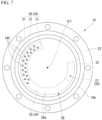
- the outer circumferential portion 22 of the partition member 16 and the holder 21 are disposed downward in this order at the lower end opening edge of the first mounting member 11 and are fixed thereto integrally by screws 23, so that the diaphragm 20 is mounted to the lower end opening of the first mounting member 11 via the partition member 16.
- the bottom portion of the diaphragm 20 is deep at the outer circumferential side and shallow at the central portion.
- various shapes conventionally known can be adopted other than such a shape.
- a first holding groove 16a that is recessed upward is formed in the lower surface of the partition member 16 facing the auxiliary liquid chamber 15 side, at a portion adjacent to the outer circumferential portion 22 on the radially inner side. As the upper end portion of the diaphragm 20 tightly abuts the first holding groove 16a, the space between the diaphragm 20 and the partition member 16 is closed.
- a restriction passage 24 that causes the main liquid chamber 14 and the auxiliary liquid chamber 15 to communicate with each other is formed.
- the restriction passage 24 includes a first communication portion 26 that is open to the main liquid chamber 14, a second communication portion 27 that is open to the auxiliary liquid chamber 15, and a main body flow path 25 that causes the first communication portion 26 and the second communication portion 27 to communicate with each other.
- the main body flow path 25 extends along the circumferential direction in the partition member 16, and the flow direction of the main body flow path 25 and the circumferential direction are coincident with each other.
- the main body flow path 25 is formed in an arc shape arranged coaxially with the central axis O1 and extends over a range in which the central angle centered on the central axis O1 exceeds 180°.
- the main body flow path 25 is defined by a first barrier 28 facing the main liquid chamber 14 and a second barrier 29 facing the auxiliary liquid chamber 15 in the partition member 16.
- Each of the first barrier 28 and the second barrier 29 is formed in a plate shape of which the front and back faces face in the axial direction.
- the first barrier 28 is axially sandwiched by the main body flow path 25 and the main liquid chamber 14 and is located between the main body flow path 25 and the main liquid chamber 14.
- the second barrier 29 is axially sandwiched by the main body flow path 25 and the auxiliary liquid chamber 15 and is located between the main body flow path 25 and the auxiliary liquid chamber 15.
- the second communication portion 27 includes one opening 32 penetrating the second barrier 29 in the axial direction.
- the opening 32 is disposed in a portion of the second barrier 29 that forms one end portion along the circumferential direction of the main body flow path 25.
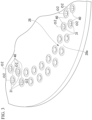
- the first communication portion 26 includes a plurality of pores 31 that penetrate the first barrier 28 in the axial direction and are arranged along the circumferential direction (the flow path direction of the main body flow path 25).
- the plurality of pores 31 are disposed in a portion of the first barrier 28 that forms the other end portion along the circumferential direction of the main body flow path 25. At least some of the plurality of pores 31 form a row of holes spaced in the circumferential direction on concentric circles centered on the central axis O1.
- the one end portion side of the main body flow path 25 along the circumferential direction is referred to as one side, and the other end portion side is referred to as the other side.
- the direction orthogonal to a central axis O2 (see FIG. 3 ) of the pore 31 is referred to as a hole radial direction, and the direction circling around the central axis O2 is referred to as a hole circumferential direction.
- Each of the plurality of pores 31 is smaller than the flow path cross-sectional area of the main body flow path 25 and is disposed inside each of the first barrier 28 and the main body flow path 25 in the plan view.
- the lengths of the plurality of pores 31 are equal to one another.
- the inner diameters of the plurality of pores 31 are equal to one another.
- the lengths and the inner diameters of the plurality of pores 31 may be made different from each other.
- a top portion 40a of the protrusion 40 is formed in an acute angle shape or a curved surface shape which gradually decreases in thickness along the hole radial direction toward the upper side in the longitudinal sectional view.
- the top portion 40a is formed in a curved surface shape protruding upward, and is located at the central portion in the hole radial direction between the inner circumferential surface and the outer circumferential surface of the protrusion 40.
- both the mounting members 11 and 12 are relatively displaced while elastically deforming the elastic body 13. Then, the liquid pressure in the main liquid chamber 14 fluctuates, and the liquid L in the main liquid chamber 14 flows into the auxiliary liquid chamber 15 through the restriction passage 24, and the liquid L in the auxiliary liquid chamber 15 flows into the main liquid chamber 14 through the restriction passage 24.
- the vibration dampening device 10 when the liquid L flows into the main liquid chamber 14 through the plurality of pores 31 from the main body flow path 25, the liquid L flows through each of the pores 31 while being subjected to pressure loss by the first barrier 28 in which the pores 31 are formed, so that the flow velocity of the liquid L flowing into the main liquid chamber 14 can be suppressed.
- the liquid L flows through the plurality of pores 31 instead of a single pore 31, the liquid L can be branched into a plural of flows and can be circulated, so that the flow velocity of the liquid L which has passed through the individual pores 31 can be reduced. Accordingly, even if a large load (vibration) is input to the vibration dampening device 10, the difference in flow velocity generated between the liquid L which has flowed into the main liquid chamber 14 through the pores 31 and the liquid L in the main liquid chamber 14 can be suppressed, so that the generation of a vortex caused by the difference in flow velocity and the generation of bubbles caused by the vortex can be suppressed.
- the bubbles generated by causing the liquid L to pass through the plurality of pores 31 can be separated from each other in the main liquid chamber 14, so that joining and growing of the bubbles are suppressed and the bubbles can be easily maintained in a finely dispersed state.
- the protrusion 40 that has an inner circumferential surface with a shape similar to that of the pore 31 in the plan view and protrudes toward the main liquid chamber 14 is formed over the entire circumference. Therefore, since the liquid L can be caused to flow from the pores 31 into the main liquid chamber 14 along the inner circumferential surface of the protrusion 40, at the opening circumferential edge portion of the pore 31 in the surface 28a of the first barrier 28, the occurrence of separation of the flow of the liquid L can be suppressed, and the velocity of the liquid L flowing from the pores 31 into the main liquid chamber 14 can be suppressed.
- the generation of bubbles themselves can be suppressed, and even if bubbles are generated, the bubbles can be easily maintained in a finely dispersed state. Therefore, even if cavitation collapse in which bubbles collapse occurs, abnormal sound generated can be suppressed.
- the protrusion 40 is formed over the entire circumference of the opening circumferential edge portion of the pore 31 in the surface 28a of the first barrier 28, at the opening circumferential edge portion of the pore 31, the occurrence of separation of the flow of the liquid can be suppressed over the entire circumference regardless of the position in the circumferential direction, and the velocity of the liquid flowing from the pores 31 into the main liquid chamber 14 or the auxiliary liquid chamber 15 can be suppressed.
- a protrusion 40B is intermittently formed over the entire circumference at the opening circumferential edge portion of the pore 31 in the surface 28a of the first barrier 28 facing the main liquid chamber 14. That is, a plurality of intermittent portions 41 are formed in the protrusion 40B at intervals in the hole circumferential direction. In the illustrated example, five intermittent portions are formed in the protrusion 40B at equal intervals in the hole circumferential direction. It is desirable that the sum of the circumferential lengths of the plurality of intermittent portions 41 is equal to or less than 20% of the circumferential length of the opening circumferential edge portion of the pore 31.
- the plurality of intermittent portions 41 are formed at portions avoiding positions having the central axis O2 interposed therebetween in the hole radial direction in the opening circumferential edge portion of the pore 31 in the surface 28a. That is, the intermittent portion 41 is opposed to the inner circumferential surface of the protrusion 40B in the hole radial direction.
- the intermittent portion 41 is opposed to the inner circumferential surface of the protrusion 40B in the hole radial direction, when the liquid flows from the main body flow path 25 into the main liquid chamber 14 through the pores 31, even if bubbles are generated at the plurality of intermittent portions 41, in a case where these bubbles flow in the main liquid chamber 14, flowing of the bubbles along the liquid flowing from the pores 31 into the main liquid chamber 14 and joining the bubbles can be suppressed.
- the protrusion that has an inner circumferential surface with a shape similar to that of the pore in the plan view and protrudes toward the first liquid chamber or the second liquid chamber is formed.
- the generation of bubbles themselves can be suppressed, and even if bubbles are generated, the bubbles can be easily maintained in a finely dispersed state. Therefore, even if cavitation collapse in which bubbles collapse occurs, abnormal sound generated can be suppressed.
- a vibration dampening device 110 is a liquid-sealed type vibration dampening device including: the cylindrical first mounting member 11 connected to any one of the vibration generating portion and the vibration receiving portion, the second mounting member 12 connected to the other of the vibration generating portion and the vibration receiving portion, the elastic body 13 which elastically connects the first mounting member 11 and the second mounting member 12 to each other, and the partition member 16 which partitions the inside of the first mounting member 11 into the main liquid chamber (first liquid chamber) 14 and the auxiliary liquid chamber (second liquid chamber) 15, which will be described later.
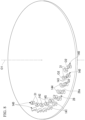
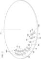
- the first wall portion 143 is formed along the hole circumferential direction, and the inner surface of the first wall portion 143 facing inward in the hole radial direction is flush with the inner circumferential surface of the pore 31. Both end portions of the first wall portion 143 in the hole circumferential direction are located in a range in which the central angle centered on the central axis O2 is 90° or less. Accordingly, when vibration is input, which will be described later, the liquid L which has flowed from the pores 31 into the main liquid chamber 14 and collides with the second wall portion 144 of the awning portion 140 can flow out not only in the extension direction but also in a direction orthogonal to this direction in the plan view.
- the position of the open end portion 142 of the second wall portion 144 in the hole radial direction is equal to a portion opposite to the portion of the opening circumferential edge portion of the pore 31 connected to be base end portion 141 in the surface 28a of the first barrier 28 with the central axis O2 interposed therebetween in the hole radial direction.
- the liquid L flows through the plurality of pores 31 instead of a single pore 31, the liquid L can be branched into a plural of flows and can be circulated, so that the flow velocity of the liquid L which has passed through the individual pores 31 can be reduced. Accordingly, even if a large load (vibration) is input to the vibration dampening device 110, the difference in flow velocity generated between the liquid L which has flowed into the main liquid chamber 14 through the pores 31 and the liquid L in the main liquid chamber 14 can be suppressed, so that the generation of a vortex caused by the difference in flow velocity and the generation of bubbles caused by the vortex can be suppressed.
- the bubbles generated by causing the liquid L to pass through the plurality of pores 31 can be separated from each other in the main liquid chamber 14, so that joining and growing of the bubbles are suppressed and the bubbles can be easily maintained in a finely dispersed state.
- the plurality of awning portions 140 covering the pores 31 are formed at the opening circumferential edge portions of the pores 31 in the surface 28a of the first barrier 28, a pressure loss can be generated by causing the liquid L that has flowed from the pores 31 into the main liquid chamber 14 to collide with the awning portions 140. Therefore, the difference in flow velocity generated between the liquid L which has flowed in as described above and the liquid in the main liquid chamber 14 can be effectively suppressed.
- the vibration dampening device since the generation of bubbles themselves can be suppressed, even if bubbles are generated, the bubbles can be easily maintained in a finely dispersed state. Therefore, even if cavitation collapse in which bubbles collapse occurs, abnormal sound generated can be suppressed.
- the vibration dampening device in the present embodiment joining and growing of the bubbles in the main liquid chamber 14 or the auxiliary liquid chamber 15 are suppressed and the bubbles can be easily maintained in a finely dispersed state.
- the awning portions 140 covering the adjacent pores 31 are arranged so that the extension directions thereof are different from each other in the plan view, the directions of the flows of the liquid L that have flowed from the adjacent pores 31 into the main liquid chamber 14 can be different from each other. Therefore, when the liquid flows from each of the pores into the main liquid chamber 14 or the auxiliary liquid chamber 15, or when the liquid L is circulated through the main body flow path 25, even if bubbles are generated, the directions of the individual bubbles flowing in the main liquid chamber 14 or the auxiliary liquid chamber 15 are different from each other. Therefore, according to the vibration dampening device in the present embodiment, joining and growing of the bubbles in the main liquid chamber 14 or the auxiliary liquid chamber 15 can be effectively suppressed and the bubbles can be more easily maintained in a finely dispersed state.
- the awning portions 140 are formed at the opening circumferential edge portions of at least the pores 31 located farthest from the second communication portion 27 along the flow path direction among the plurality of pores 31, the pores 31 at which the flow rate of the liquid L flowing through the main body flow path 25 increases due to the inertia of the liquid L are covered by the awning portions 140. Therefore, a pressure loss can be generated by causing the liquid L that has flowed from the pores 31 at which the flow rate is high to collide with the awning portions 140, and the difference in flow velocity generated between the liquid L which has flowed into the main liquid chamber 14 and the liquid L in the main liquid chamber 14 can be more effectively suppressed.
- an awning portion 140B includes a pair of side wall portions 146 covering the awning portion 140B from both sides in a direction orthogonal to the extension direction of the awning portion 140B in the plan view.
- the side wall portions 146 connects both ends of each of the first wall portion 143 and the second wall portion 144 in the hole circumferential direction and are connected to the opening circumferential edge portion of the pore 31 in the surface 28a.
- the pair of side wall portions 146 are formed integrally with the first wall portion 143 and the second wall portion 144.
- the awning portion 140B is disposed over a range in which the central angle centered on the central axis O2 is 270° in the opening circumferential edge portion of the pore 31 in the surface 28a of the first barrier 28.
- the awning portions have the base end portion connected to the barrier, and may be arranged so that two or more of the plurality of the awning portions are different from each other in the direction from the central portion of the pore in the hole circumferential direction around the central axis at the base end portion of the awning portion to the central portion in the hole circumferential direction at the open end portion of the awning portion in the plan view.
- the technical scope of the present invention is not limited to the embodiment described above, and various modifications can be made without departing from the scope of the present invention.
- the configuration in which the top portion 40a of the protrusions 40 and 40B is formed in an acute angle shape or a curved surface shape is described, but the top portion 40a is not limited to such an aspect.
- the top portion 40a may be formed on a flat surface.
- the extension directions of the awning portions 140 covering the adjacent pores 31 are different from each other is described, but the extension directions are not limited to such an aspect.
- the extension directions of a plurality of the awning portions 140 covering the adjacent pores 31 may be the same.
- the configuration in which the plurality of the pores 31 are formed in the first barrier 28 at intervals in the flow path direction of the main body flow path 25 is described, but the pores 31 are not limited to such an aspect.
- One pore 31 may be formed in the first barrier 28 or the second barrier 29.
- the configuration in which the awning portion 140 is formed at the opening circumferential edge portion of at least the pore 31 located farthest from the second communication portion 27 along the flow path direction, among the plurality of pores 31, is described, but the awning portion 140 is not limited to such an aspect.
- the awning portion 140 may be formed only at the opening circumferential edge portion of the pore 31 which is located farthest from the first communication portion 26 along the flow path direction.
- the pore 31 is formed in cylindrical shape (straight circular hole shape), but may be formed in a truncated cone shape which gradually decreases in diameter.
- the plurality of pores 31 are formed in a circular shape in a transversal sectional view, but the present invention is not limited thereto.
- an appropriate change can be made, for example, by forming the plurality of pores 31 in an angular shape in the transversal sectional view.
- the first communication portion 26 includes the plurality of pores 31, but for example, may have a configuration having both openings with a larger diameter than the pores 31 and the pores 31.
- the second communication portion 27 may include a plurality of openings 32 arranged along the circumferential direction (the flow path direction of the main body flow path 25).
- the partition member 16 is disposed at the lower end portion of the first mounting member 11, and the outer circumferential portion 22 of the partition member 16 is caused to abut the lower end opening edge of the first mounting member 11.
- the auxiliary liquid chamber 15 may be formed over a range from the lower end portion of the first mounting member 11 to the bottom surface of the diaphragm 20.
- the compression type vibration dampening device 10 in which a positive pressure acts on the main liquid chamber 14 due to the application of a support load is described.
- the embodiment is also applicable to a suspension type vibration dampening device in which the main liquid chamber 14 is located on the lower side in the vertical direction, the auxiliary liquid chamber 15 is mounted so as to be located on the upper side in the vertical direction, and a negative pressure is applied to the main liquid chamber 14 as a support load is applied.
- the partition member 16 partitions the liquid chamber 19 in the first mounting member 11 into the main liquid chamber 14 having the elastic body 13 in a portion of the wall surface and the auxiliary liquid chamber 15, but is not limited thereto.
- a pair of elastic bodies 13 may be provided, and instead of providing the auxiliary liquid chamber 15, a pressure receiving liquid chamber having the elastic body 13 in a portion of the wall surface may be provided.
- a change to another configuration in which the partition member 16 partitions the liquid chamber 19 in the first mounting member 11 in which the liquid L is sealed into the first liquid chamber 14 and the second liquid chamber 15, and at least one of the first liquid chamber 14 and the second liquid chamber 15 has elastic body 13 in a portion of the wall surface is possible as appropriate.
Landscapes
- Engineering & Computer Science (AREA)
- Mechanical Engineering (AREA)
- General Engineering & Computer Science (AREA)
- Chemical & Material Sciences (AREA)
- Combustion & Propulsion (AREA)
- Transportation (AREA)
- Combined Devices Of Dampers And Springs (AREA)
Claims (3)
- Schwingungsdämpfungsvorrichtung (10, 110) des Flüssigkeitsverschlusstyps, die Folgendes umfasst:ein zylindrisches erstes Anbringungselement (11), das mit einem beliebigen von einem Schwingungserzeugungsabschnitt und einem Schwingungsaufnahmeabschnitt verbunden ist, und ein zweites Anbringungselement (12), das mit dem anderen verbunden ist,einen elastischen Körper (13), das die beiden Anbringungselemente (11, 12) elastisch miteinander verbindet, undein Unterteilungselement (16), das eine Flüssigkeitskammer (19) in dem ersten Anbringungselement (11), in der eine Flüssigkeit verschlossen ist, in eine erste Flüssigkeitskammer (14) und eine zweite Flüssigkeitskammer (15) unterteilt,wobei ein Verengungsdurchgang (24), der bewirkt, dass die erste Flüssigkeitskammer (14) und die zweite Flüssigkeitskammer (15) in Verbindung miteinander stehen, in dem Unterteilungselement (16) geformt ist,der Verengungsdurchgang (24) einen ersten Verbindungsabschnitt (26), der zu der ersten Flüssigkeitskammer (14) offen ist, einen zweiten Verbindungsabschnitt (27), der zu der zweiten Flüssigkeitskammer (15) offen ist, und eine Hauptkörper-Strömungsbahn (25), die bewirkt, dass der erste Verbindungsabschnitt (26) und der zweite Verbindungsabschnitt (27) in Verbindung miteinander stehen, einschließt, undmindestens einer von dem ersten Verbindungsabschnitt (26) und dem zweiten Verbindungsabschnitt (27) eine Vielzahl von Poren (31) einschließt, die eine Sperre (28, 29) durchdringen, die eine Oberfläche (28a, 29a) aufweist, die zu der ersten Flüssigkeitskammer (14) oder der zweiten Flüssigkeitskammer (15) zeigt,ein Vorsprung (40, 40B), der von der Oberfläche (28a), die zu der ersten Flüssigkeitskammer (14) zeigt, zu der ersten Flüssigkeitskammer (14) hin vorspringt oder der von der Oberfläche (29a), die zu der zweiten Flüssigkeitskammer (15) zeigt, zu der zweiten Flüssigkeitskammer (15) hin vorspringt, an einem Öffnungsumfangskantenabschnitt mindestens einer Pore (31) unter der Vielzahl von Poren (31) in der Oberfläche (28a, 29a) der Sperre (28, 29) geformt ist, undeine Innenumfangsfläche des Vorsprungs (40, 40B) mit der Innenumfangsfläche der Pore (31) in der Lochradialrichtung ohne einen gestuften Abschnitt verbunden ist,wobei der Vorsprung (40, 40B) ein Verdeckabschnitt (140, 140B, 140C) ist, der geformt ist, um die Pore (31) abzudecken,wobei der Verdeckabschnitt (140, 140B, 140C) einen Basisendabschnitt (141), der mit der Sperre (28, 29) verbunden ist, und einem offenen Endabschnitt (142) aufweist,dadurch gekennzeichnet, dasszwei oder mehr von einer Vielzahl der Verdeckabschnitte (140, 140B, 140C) so angeordnet sind, dass sie sich in einer Richtung von einem mittigen Abschnitt in einer Lochumfangsrichtung um eine Mittelachse (O2) der Pore (31) an dem Basisendabschnitt (141) des Verdeckabschnitts (140, 140B, 140C) bis zu einem mittigen Abschnitt in der Lochumfangsrichtung an dem offenen Endabschnitt (142) des Verdeckabschnitts (140, 140B, 140C) in einer Draufsicht der Sperre (28, 29) voneinander unterscheiden,der Verdeckabschnitt (140, 140B, 140C) Folgendes einschließt:einen ersten Wandabschnitt (143), der den Basisendabschnitt (141) einschließt, der mit der Sperre (28, 29) verbunden ist, und sich von der Oberfläche (28a), die zu der ersten Flüssigkeitskammer (14) zeigt, zu der ersten Flüssigkeitskammer (14) hin erstreckt oder sich von der Oberfläche (29a), die zu der zweiten Flüssigkeitskammer (15) zeigt, zu der zweiten Flüssigkeitskammer (15) hin erstreckt,einen zweiten Wandabschnitt (144), der sich in der Lochradialrichtung von dem Ende des ersten Wandabschnitts (143) aus nach innen erstreckt, das sich auf der Seite, entgegengesetzt zu dem Basisendabschnitt (141), befindet,einen Verbindungsabschnitt (145) zwischen dem ersten Wandabschnitt (143) und dem zweiten Wandabschnitt (144), der in einer gekrümmten Oberflächengestalt geformt ist, die in der Lochradialrichtung nach außen vorspringt, undder offene Endabschnitt (142) ein Abschnitt des zweiten Wandabschnitts (144) ist, der sich auf der Seite, entgegengesetzt zu dem Verbindungsabschnitt (145), befindet, wobei die Mittelachse (O2) der Pore (31) in der Lochradialrichtung zwischen denselben eingefügt ist.
- Schwingungsdämpfungsvorrichtung (110) nach Anspruch 1,
wobei die Verdeckabschnitte (140, 140B, 140C), welche die zueinander benachbarten Poren (31) abdecken, so angeordnet sind, dass sie sich in der Richtung von dem mittigen Abschnitt in der Lochumfangsrichtung an dem Basisendabschnitt (141) des Verdeckabschnitts (140, 140B, 140C) bis zu dem mittigen Abschnitt in der Lochumfangsrichtung an dem offenen Endabschnitt (142) des Verdeckabschnitts (140, 140B, 140C), in der Draufsicht voneinander unterscheiden. - Schwingungsdämpfungsvorrichtung nach Anspruch 1 oder Anspruch 2,wobei die Vielzahl von Poren (31) in der Sperre (28, 29) in Abständen in einer Strömungsbahnrichtung der Hauptkörper-Strömungsbahn (25) geformt sind, undder Vorsprung (40, 40B, 140, 140B, 140C) an dem Öffnungsumfangskantenabschnitt mindestens der Pore (31) geformt ist, die sich am weitesten von dem anderen von dem ersten Verbindungsabschnitt (26) und dem zweiten Verbindungsabschnitt (27) entlang der Strömungsbahnrichtung, unter der Vielzahl von Poren (31), in der Oberfläche (28a, 29a) der Sperre (28, 29) befindet.
Applications Claiming Priority (3)
| Application Number | Priority Date | Filing Date | Title |
|---|---|---|---|
| JP2017081261A JP6871050B2 (ja) | 2017-04-17 | 2017-04-17 | 防振装置 |
| JP2017098940A JP7161842B2 (ja) | 2017-05-18 | 2017-05-18 | 防振装置 |
| PCT/JP2018/014887 WO2018193895A1 (ja) | 2017-04-17 | 2018-04-09 | 防振装置 |
Publications (3)
| Publication Number | Publication Date |
|---|---|
| EP3614015A1 EP3614015A1 (de) | 2020-02-26 |
| EP3614015A4 EP3614015A4 (de) | 2021-01-27 |
| EP3614015B1 true EP3614015B1 (de) | 2025-07-09 |
Family
ID=63855799
Family Applications (1)
| Application Number | Title | Priority Date | Filing Date |
|---|---|---|---|
| EP18788410.1A Active EP3614015B1 (de) | 2017-04-17 | 2018-04-09 | Schwingungsdämpfungsvorrichtung |
Country Status (4)
| Country | Link |
|---|---|
| US (1) | US11371578B2 (de) |
| EP (1) | EP3614015B1 (de) |
| CN (1) | CN110506168B (de) |
| WO (1) | WO2018193895A1 (de) |
Families Citing this family (1)
| Publication number | Priority date | Publication date | Assignee | Title |
|---|---|---|---|---|
| JP6983060B2 (ja) | 2017-12-26 | 2021-12-17 | 株式会社ブリヂストン | 防振装置 |
Family Cites Families (15)
| Publication number | Priority date | Publication date | Assignee | Title |
|---|---|---|---|---|
| JP4922871B2 (ja) * | 2007-08-31 | 2012-04-25 | 東海ゴム工業株式会社 | 流体封入式防振装置 |
| JP5363093B2 (ja) | 2008-04-16 | 2013-12-11 | 東海ゴム工業株式会社 | 流体封入式防振装置 |
| DE112009002210B4 (de) * | 2008-09-17 | 2020-03-05 | Toyota Jidosha Kabushiki Kaisha | Schwingungsabsorber mit eingeschlossener Flüssigkeit |
| JP5535958B2 (ja) | 2011-02-24 | 2014-07-02 | 東洋ゴム工業株式会社 | 液封入式防振装置 |
| JP2015025515A (ja) * | 2013-07-26 | 2015-02-05 | 株式会社ブリヂストン | 防振装置 |
| US10066695B2 (en) | 2013-11-11 | 2018-09-04 | Bridgestone Corporation | Vibration damping device |
| WO2015122034A1 (ja) | 2014-02-17 | 2015-08-20 | 株式会社ブリヂストン | 防振装置 |
| JP6300406B2 (ja) | 2014-04-24 | 2018-03-28 | 株式会社ブリヂストン | 防振装置 |
| JP6300407B2 (ja) * | 2014-04-30 | 2018-03-28 | 株式会社ブリヂストン | 防振装置 |
| JP6448926B2 (ja) | 2014-06-23 | 2019-01-09 | 住友理工株式会社 | 流体封入式防振装置 |
| CN106574683B (zh) * | 2014-08-20 | 2019-03-05 | 株式会社普利司通 | 隔振装置 |
| JP6450619B2 (ja) * | 2015-03-19 | 2019-01-09 | 株式会社ブリヂストン | 防振装置 |
| JP2017081261A (ja) | 2015-10-26 | 2017-05-18 | スズキ株式会社 | ステレオカメラのカバー |
| KR101676255B1 (ko) | 2015-11-02 | 2016-11-29 | 현대자동차주식회사 | 엔진마운트 |
| JP6702100B2 (ja) | 2015-11-18 | 2020-05-27 | カシオ計算機株式会社 | 情報処理装置、情報処理方法、及び、プログラム |
-
2018
- 2018-04-09 EP EP18788410.1A patent/EP3614015B1/de active Active
- 2018-04-09 WO PCT/JP2018/014887 patent/WO2018193895A1/ja not_active Ceased
- 2018-04-09 CN CN201880024851.6A patent/CN110506168B/zh active Active
- 2018-04-09 US US16/603,999 patent/US11371578B2/en active Active
Also Published As
| Publication number | Publication date |
|---|---|
| EP3614015A1 (de) | 2020-02-26 |
| CN110506168A (zh) | 2019-11-26 |
| CN110506168B (zh) | 2021-06-25 |
| US11371578B2 (en) | 2022-06-28 |
| EP3614015A4 (de) | 2021-01-27 |
| US20200049223A1 (en) | 2020-02-13 |
| WO2018193895A1 (ja) | 2018-10-25 |
Similar Documents
| Publication | Publication Date | Title |
|---|---|---|
| EP3273089B1 (de) | Schwingungsdämpfungsvorrichtung | |
| EP3617547B1 (de) | Vibrationsdämpfungsvorrichtung | |
| EP3070365B1 (de) | Schwingungsdämpfungsvorrichtung | |
| WO2019131043A1 (ja) | 防振装置 | |
| CN109073033B (zh) | 隔振装置 | |
| EP3477148B1 (de) | Vibrationsdämpfungsvorrichtung | |
| EP3617546B1 (de) | Vibrationsdämpfungsvorrichtung | |
| EP3614015B1 (de) | Schwingungsdämpfungsvorrichtung | |
| JP6986488B2 (ja) | 防振装置 | |
| JP6836458B2 (ja) | 防振装置 | |
| EP3477146B1 (de) | Vibrationsdämpfungsvorrichtung | |
| JP6853674B2 (ja) | 防振装置 | |
| JP6822860B2 (ja) | 防振装置 | |
| JP6871050B2 (ja) | 防振装置 | |
| JP7161842B2 (ja) | 防振装置 | |
| JP6986489B2 (ja) | 防振装置 |
Legal Events
| Date | Code | Title | Description |
|---|---|---|---|
| STAA | Information on the status of an ep patent application or granted ep patent |
Free format text: STATUS: THE INTERNATIONAL PUBLICATION HAS BEEN MADE |
|
| PUAI | Public reference made under article 153(3) epc to a published international application that has entered the european phase |
Free format text: ORIGINAL CODE: 0009012 |
|
| STAA | Information on the status of an ep patent application or granted ep patent |
Free format text: STATUS: REQUEST FOR EXAMINATION WAS MADE |
|
| 17P | Request for examination filed |
Effective date: 20191004 |
|
| AK | Designated contracting states |
Kind code of ref document: A1 Designated state(s): AL AT BE BG CH CY CZ DE DK EE ES FI FR GB GR HR HU IE IS IT LI LT LU LV MC MK MT NL NO PL PT RO RS SE SI SK SM TR |
|
| AX | Request for extension of the european patent |
Extension state: BA ME |
|
| DAV | Request for validation of the european patent (deleted) | ||
| DAX | Request for extension of the european patent (deleted) | ||
| A4 | Supplementary search report drawn up and despatched |
Effective date: 20210112 |
|
| RIC1 | Information provided on ipc code assigned before grant |
Ipc: B60K 5/12 20060101ALI20201221BHEP Ipc: F16F 13/10 20060101AFI20201221BHEP |
|
| RAP1 | Party data changed (applicant data changed or rights of an application transferred) |
Owner name: PROSPIRA CORPORATION |
|
| STAA | Information on the status of an ep patent application or granted ep patent |
Free format text: STATUS: EXAMINATION IS IN PROGRESS |
|
| 17Q | First examination report despatched |
Effective date: 20240408 |
|
| GRAP | Despatch of communication of intention to grant a patent |
Free format text: ORIGINAL CODE: EPIDOSNIGR1 |
|
| STAA | Information on the status of an ep patent application or granted ep patent |
Free format text: STATUS: GRANT OF PATENT IS INTENDED |
|
| INTG | Intention to grant announced |
Effective date: 20250206 |
|
| P01 | Opt-out of the competence of the unified patent court (upc) registered |
Free format text: CASE NUMBER: APP_8521/2025 Effective date: 20250219 |
|
| GRAS | Grant fee paid |
Free format text: ORIGINAL CODE: EPIDOSNIGR3 |
|
| GRAA | (expected) grant |
Free format text: ORIGINAL CODE: 0009210 |
|
| STAA | Information on the status of an ep patent application or granted ep patent |
Free format text: STATUS: THE PATENT HAS BEEN GRANTED |
|
| AK | Designated contracting states |
Kind code of ref document: B1 Designated state(s): AL AT BE BG CH CY CZ DE DK EE ES FI FR GB GR HR HU IE IS IT LI LT LU LV MC MK MT NL NO PL PT RO RS SE SI SK SM TR |
|
| REG | Reference to a national code |
Ref country code: GB Ref legal event code: FG4D |
|
| REG | Reference to a national code |
Ref country code: CH Ref legal event code: EP |
|
| REG | Reference to a national code |
Ref country code: IE Ref legal event code: FG4D |
|
| REG | Reference to a national code |
Ref country code: DE Ref legal event code: R096 Ref document number: 602018083433 Country of ref document: DE |
|
| REG | Reference to a national code |
Ref country code: NL Ref legal event code: MP Effective date: 20250709 |
|
| PG25 | Lapsed in a contracting state [announced via postgrant information from national office to epo] |
Ref country code: PT Free format text: LAPSE BECAUSE OF FAILURE TO SUBMIT A TRANSLATION OF THE DESCRIPTION OR TO PAY THE FEE WITHIN THE PRESCRIBED TIME-LIMIT Effective date: 20251110 |
|
| PG25 | Lapsed in a contracting state [announced via postgrant information from national office to epo] |
Ref country code: NL Free format text: LAPSE BECAUSE OF FAILURE TO SUBMIT A TRANSLATION OF THE DESCRIPTION OR TO PAY THE FEE WITHIN THE PRESCRIBED TIME-LIMIT Effective date: 20250709 |
|
| REG | Reference to a national code |
Ref country code: AT Ref legal event code: MK05 Ref document number: 1812061 Country of ref document: AT Kind code of ref document: T Effective date: 20250709 |
|
| PG25 | Lapsed in a contracting state [announced via postgrant information from national office to epo] |
Ref country code: IS Free format text: LAPSE BECAUSE OF FAILURE TO SUBMIT A TRANSLATION OF THE DESCRIPTION OR TO PAY THE FEE WITHIN THE PRESCRIBED TIME-LIMIT Effective date: 20251109 |
|
| PG25 | Lapsed in a contracting state [announced via postgrant information from national office to epo] |
Ref country code: NO Free format text: LAPSE BECAUSE OF FAILURE TO SUBMIT A TRANSLATION OF THE DESCRIPTION OR TO PAY THE FEE WITHIN THE PRESCRIBED TIME-LIMIT Effective date: 20251009 |
|
| REG | Reference to a national code |
Ref country code: LT Ref legal event code: MG9D |
|
| PG25 | Lapsed in a contracting state [announced via postgrant information from national office to epo] |
Ref country code: AT Free format text: LAPSE BECAUSE OF FAILURE TO SUBMIT A TRANSLATION OF THE DESCRIPTION OR TO PAY THE FEE WITHIN THE PRESCRIBED TIME-LIMIT Effective date: 20250709 |
|
| PG25 | Lapsed in a contracting state [announced via postgrant information from national office to epo] |
Ref country code: FI Free format text: LAPSE BECAUSE OF FAILURE TO SUBMIT A TRANSLATION OF THE DESCRIPTION OR TO PAY THE FEE WITHIN THE PRESCRIBED TIME-LIMIT Effective date: 20250709 |
|
| PG25 | Lapsed in a contracting state [announced via postgrant information from national office to epo] |
Ref country code: HR Free format text: LAPSE BECAUSE OF FAILURE TO SUBMIT A TRANSLATION OF THE DESCRIPTION OR TO PAY THE FEE WITHIN THE PRESCRIBED TIME-LIMIT Effective date: 20250709 |
|
| PG25 | Lapsed in a contracting state [announced via postgrant information from national office to epo] |
Ref country code: GR Free format text: LAPSE BECAUSE OF FAILURE TO SUBMIT A TRANSLATION OF THE DESCRIPTION OR TO PAY THE FEE WITHIN THE PRESCRIBED TIME-LIMIT Effective date: 20251010 |
|
| PG25 | Lapsed in a contracting state [announced via postgrant information from national office to epo] |
Ref country code: SE Free format text: LAPSE BECAUSE OF FAILURE TO SUBMIT A TRANSLATION OF THE DESCRIPTION OR TO PAY THE FEE WITHIN THE PRESCRIBED TIME-LIMIT Effective date: 20250709 |
|
| PG25 | Lapsed in a contracting state [announced via postgrant information from national office to epo] |
Ref country code: LV Free format text: LAPSE BECAUSE OF FAILURE TO SUBMIT A TRANSLATION OF THE DESCRIPTION OR TO PAY THE FEE WITHIN THE PRESCRIBED TIME-LIMIT Effective date: 20250709 |
|
| PG25 | Lapsed in a contracting state [announced via postgrant information from national office to epo] |
Ref country code: PL Free format text: LAPSE BECAUSE OF FAILURE TO SUBMIT A TRANSLATION OF THE DESCRIPTION OR TO PAY THE FEE WITHIN THE PRESCRIBED TIME-LIMIT Effective date: 20250709 Ref country code: BG Free format text: LAPSE BECAUSE OF FAILURE TO SUBMIT A TRANSLATION OF THE DESCRIPTION OR TO PAY THE FEE WITHIN THE PRESCRIBED TIME-LIMIT Effective date: 20250709 |
|
| PG25 | Lapsed in a contracting state [announced via postgrant information from national office to epo] |
Ref country code: RS Free format text: LAPSE BECAUSE OF FAILURE TO SUBMIT A TRANSLATION OF THE DESCRIPTION OR TO PAY THE FEE WITHIN THE PRESCRIBED TIME-LIMIT Effective date: 20251009 |
|
| PG25 | Lapsed in a contracting state [announced via postgrant information from national office to epo] |
Ref country code: ES Free format text: LAPSE BECAUSE OF FAILURE TO SUBMIT A TRANSLATION OF THE DESCRIPTION OR TO PAY THE FEE WITHIN THE PRESCRIBED TIME-LIMIT Effective date: 20250709 |
|
| PG25 | Lapsed in a contracting state [announced via postgrant information from national office to epo] |
Ref country code: SM Free format text: LAPSE BECAUSE OF FAILURE TO SUBMIT A TRANSLATION OF THE DESCRIPTION OR TO PAY THE FEE WITHIN THE PRESCRIBED TIME-LIMIT Effective date: 20250709 |
|
| PG25 | Lapsed in a contracting state [announced via postgrant information from national office to epo] |
Ref country code: DK Free format text: LAPSE BECAUSE OF FAILURE TO SUBMIT A TRANSLATION OF THE DESCRIPTION OR TO PAY THE FEE WITHIN THE PRESCRIBED TIME-LIMIT Effective date: 20250709 |
|
| PG25 | Lapsed in a contracting state [announced via postgrant information from national office to epo] |
Ref country code: IT Free format text: LAPSE BECAUSE OF FAILURE TO SUBMIT A TRANSLATION OF THE DESCRIPTION OR TO PAY THE FEE WITHIN THE PRESCRIBED TIME-LIMIT Effective date: 20250709 |