EP3616438B1 - Zellenauswahltechniken für gerichtete kommunikation - Google Patents
Zellenauswahltechniken für gerichtete kommunikation Download PDFInfo
- Publication number
- EP3616438B1 EP3616438B1 EP17735264.8A EP17735264A EP3616438B1 EP 3616438 B1 EP3616438 B1 EP 3616438B1 EP 17735264 A EP17735264 A EP 17735264A EP 3616438 B1 EP3616438 B1 EP 3616438B1
- Authority
- EP
- European Patent Office
- Prior art keywords
- cell
- circuitry
- metrics
- outage
- metric
- Prior art date
- Legal status (The legal status is an assumption and is not a legal conclusion. Google has not performed a legal analysis and makes no representation as to the accuracy of the status listed.)
- Active
Links
Images


Classifications
-
- H—ELECTRICITY
- H04—ELECTRIC COMMUNICATION TECHNIQUE
- H04B—TRANSMISSION
- H04B7/00—Radio transmission systems, i.e. using radiation field
- H04B7/02—Diversity systems; Multi-antenna system, i.e. transmission or reception using multiple antennas
- H04B7/04—Diversity systems; Multi-antenna system, i.e. transmission or reception using multiple antennas using two or more spaced independent antennas
- H04B7/06—Diversity systems; Multi-antenna system, i.e. transmission or reception using multiple antennas using two or more spaced independent antennas at the transmitting station
- H04B7/0686—Hybrid systems, i.e. switching and simultaneous transmission
- H04B7/0695—Hybrid systems, i.e. switching and simultaneous transmission using beam selection
- H04B7/06952—Selecting one or more beams from a plurality of beams, e.g. beam training, management or sweeping
- H04B7/0696—Determining beam pairs
-
- H—ELECTRICITY
- H04—ELECTRIC COMMUNICATION TECHNIQUE
- H04B—TRANSMISSION
- H04B7/00—Radio transmission systems, i.e. using radiation field
- H04B7/02—Diversity systems; Multi-antenna system, i.e. transmission or reception using multiple antennas
- H04B7/04—Diversity systems; Multi-antenna system, i.e. transmission or reception using multiple antennas using two or more spaced independent antennas
- H04B7/08—Diversity systems; Multi-antenna system, i.e. transmission or reception using multiple antennas using two or more spaced independent antennas at the receiving station
- H04B7/0868—Hybrid systems, i.e. switching and combining
- H04B7/088—Hybrid systems, i.e. switching and combining using beam selection
-
- H—ELECTRICITY
- H04—ELECTRIC COMMUNICATION TECHNIQUE
- H04W—WIRELESS COMMUNICATION NETWORKS
- H04W36/00—Hand-off or reselection arrangements
- H04W36/0005—Control or signalling for completing the hand-off
- H04W36/0083—Determination of parameters used for hand-off, e.g. generation or modification of neighbour cell lists
- H04W36/00835—Determination of neighbour cell lists
-
- H—ELECTRICITY
- H04—ELECTRIC COMMUNICATION TECHNIQUE
- H04W—WIRELESS COMMUNICATION NETWORKS
- H04W36/00—Hand-off or reselection arrangements
- H04W36/06—Reselecting a communication resource in the serving access point
-
- H—ELECTRICITY
- H04—ELECTRIC COMMUNICATION TECHNIQUE
- H04W—WIRELESS COMMUNICATION NETWORKS
- H04W36/00—Hand-off or reselection arrangements
- H04W36/24—Reselection being triggered by specific parameters
- H04W36/30—Reselection being triggered by specific parameters by measured or perceived connection quality data
- H04W36/302—Reselection being triggered by specific parameters by measured or perceived connection quality data due to low signal strength
-
- H—ELECTRICITY
- H04—ELECTRIC COMMUNICATION TECHNIQUE
- H04W—WIRELESS COMMUNICATION NETWORKS
- H04W88/00—Devices specially adapted for wireless communication networks, e.g. terminals, base stations or access point devices
- H04W88/08—Access point devices
- H04W88/085—Access point devices with remote components
Definitions
- the present disclosure relates to mobile communication and, more particularly to beam adaptation techniques for mobile communications.
- Mobile communication including cellular communication, involves the transfer of data between mobile devices.
- the use of mobile communication is continuously increasing. Additionally, the bandwidth or data rate used and needed for mobile communications is continuously increasing.
- Some of the wavelengths used in mobile communication can be directional and/or sensitive to blocking.
- the blocking can be due to buildings, foliage, vehicle traffic, pedestrian traffic and the like.
- the blocking can make reliable communication challenging.
- WO 2016/138655 A1 discloses methods and apparatus for cell selection, cell reselection, and beam selection in millimetre wave systems.
- the UE measures signal strength, or signal quality or both of them to get the best consolidation measurement result.
- the UE selects the cell with the best consolidation measurement result, or selects the cell containing the candidate control beam found firstly.
- Cell Reselection the serving cell and neighbouring cells are ranked based on the consolidation measurement result.
- the UE selects one or more than one best control beams as the serving control beam to acquire system information and monitor paging message.
- EP 3,206,433 A1 discloses an inter-small cell handover method, device, and system.
- the UE needs to perform synchronous measurement only on each available beam pair in a set of available small cells determined by the UE, thereby reducing a delay of re-accessing a high frequency network by the UE, and improving QoS of receiving a high frequency service by the UE.
- the inter-small cell handover method includes: performing, by UE, synchronous measurement, to determine a set of small cells available for the UE; sending the set of available small cells to a macro base station; when the UE is in a coverage hole of a current serving small cell, receiving, by the UE, a first synchronization indication sent by the macro base station; performing synchronous measurement according to the first synchronization indication, to select an available target beam pair; and handing over to a target small cell corresponding to the available target beam pair.
- US 2012/052828 A1 discloses a method comprising scanning beams of a multiple beam antenna to collect metrics associated with the beams; selecting a best beam based on the collected metrics or based on a manual selection received from an operator; retrieving thresholds associated with the metrics; comparing the collected metrics, associated with the selected best beam, to the retrieved thresholds; and determining whether the antenna unit is in an acceptable location based on the comparison.
- Another method includes scanning beams of the multiple beam antenna to collect metrics associated with the beams; selecting a best beam based on the collected metrics; determining a serving beam; comparing a set of metrics associated with the selected best beam with a corresponding set of metrics associated with the serving beam; and determining whether to switch from the serving beam to the selected best beam based on the comparison.
- a component can be a processor (e.g., a microprocessor, a controller, or other processing device), a process running on a processor, a controller, an object, an executable, a program, a storage device, a computer, a tablet PC, an electronic circuit and/or a mobile phone with a processing device.
- a processor e.g., a microprocessor, a controller, or other processing device
- an application running on a server and the server can also be a component.
- One or more components can reside within a process, and a component can be localized on one computer and/or distributed between two or more computers.
- a set of elements or a set of other components can be described herein, in which the term "set" can be interpreted as "one or more.”
- these components can execute from various computer readable storage media having various data structures stored thereon such as with a module, for example.
- the components can communicate via local and/or remote processes such as in accordance with a signal having one or more data packets (e.g., data from one component interacting with another component in a local system, distributed system, and/or across a network, such as, the Internet, a local area network, a wide area network, or similar network with other systems via the signal).
- a signal having one or more data packets (e.g., data from one component interacting with another component in a local system, distributed system, and/or across a network, such as, the Internet, a local area network, a wide area network, or similar network with other systems via the signal).
- a component can be an apparatus with specific functionality provided by mechanical parts operated by electric or electronic circuitry, in which the electric or electronic circuitry can be operated by a software application or a firmware application executed by one or more processors.
- the one or more processors can be internal or external to the apparatus and can execute at least a part of the software or firmware application.
- a component can be an apparatus that provides specific functionality through electronic components without mechanical parts; the electronic components can include one or more processors therein to execute software and/or firmware that confer(s), at least in part, the functionality of the electronic components.
- circuitry may refer to, be part of, or include an Application Specific Integrated Circuit (ASIC), an electronic circuit, a processor (shared, dedicated, or group), and/or memory (shared, dedicated, or group) that execute one or more software or firmware programs, a combinational logic circuit, and/or other suitable hardware components that provide the described functionality.
- ASIC Application Specific Integrated Circuit
- the circuitry may be implemented in, or functions associated with the circuitry may be implemented by, one or more software or firmware modules.
- circuitry may include logic, at least partially operable in hardware.
- Some metrics for next generation (5G) wireless networks are related to cell formation, cell association and handover for millimeter-wave (mmWave) communication.
- cell formation pertains to grouping of transmit receive points (TRPs) to form a cell.
- TRPs transmit receive points
- multiple TRPs can comprise a cell.
- One associated metric is a rate based metric.
- Another metric is outage probability due to a blocker or blockage.
- the blocker is an object, such as a tree or vehicle, that blocks signals or beams from a cell to a node or device.
- Directional communications such as mmWave communication, are susceptible to blockers and/or blockage.
- the output probability is offered by each candidate cell.
- the outage probability can be derived from raw beam measurements. Additionally, proxy metrics for outage probability are provided. The proxy metrics are proportional to beam separation/correlation.
- Various embodiments and/or techniques are provided that facilitate cell related activities including cell association, cell formation and cell handover.
- the techniques utilize additional metrics including, but not limited to, cell blockage probability.
- Fig. 1 is a diagram illustrating an arrangement 100 for directional mobile communications that facilitates cell related activities.
- the directional communications include millimetre-wave (mmWave) communications and the like.
- the cell related activities include cell association, cell formation and cell handover based on one or more metrics that include cell outage probability for candidate cells.
- the outage probability is associated with directional communications, such as millimetre-wave (mmWave) communications.
- the arrangement 100 can also be an apparatus, system and the like.
- the arrangement 100 mitigates outage probability, enhances a data rate available from a chosen cell, enhances an average rate, mitigates outages given that an associated rate exceeds a threshold and enhances data rate given that an association outage is below a threshold.
- the arrangement 100 includes a user equipment (UE) device 102, a transceiver 106, and nodes 120.
- the nodes 120 include components such as, but not limited to, a packet gateway (PGW), a secondary gateway (SGW), a mobility management entity (MME), a packet data network (PDN), UEs, evolved Node Bs (eNodeB) or (eNB), access points (AP), base stations (BS) and the like.
- the nodes 120 can also include network (NW) nodes.
- the term network node refers to a node operated by a network operator and may share information with other nodes, such as UE devices.
- a node 124 is shown as an eNodeB. However, it is appreciated that the node 124 can be one of the other types shown above.
- the UE 102 includes the transceiver 106, a storage component 118, and control circuitry or controller 104.
- the storage component 118 includes a memory, storage element and the like and is configured to store information for the UE 102.
- the controller 104 is configured to perform various operations associated with the UE 102.
- the controller 104 can include logic, components, circuitry, one or more processors and the like. Further, the controller 104 can include and/or be part of baseband circuitry.
- the transceiver 106 includes transmitter functionality and receiver functionality. Further, the transceiver 106 is associated with RF circuitry.
- the UE 102 also includes one or more antenna 108 for communications with the network entities 120.
- the eNodeB 124 includes a transceiver, a storage component, and control circuitry or controller.
- the storage component includes a memory, storage element and the like and is configured to store information for the eNodeB 124.
- the controller is configured to perform various operations associated with the eNodeB 124.
- the controller can include logic, components, circuitry, one or more processors and the like.
- the transceiver 106 includes transmitter functionality and receiver functionality.
- the eNodeB 124 can also include one or more antenna for communications with the nodes 120 and/or other UEs.
- the UE 102 can be another type of node, such as the types of nodes described above including, but not limited to an eNodeB, BS, and the like.
- the UE 102 is configured to perform and/or facilitate cell related activities including cell selection, cell handover and cell formation for directional communications, such as mmWave networks/communication.
- Cell formation describes grouping of one or more transmit receive points (TRPs) to form a cell.
- TRPs transmit receive points
- the cell related activities are performed and/or facilitated based on one or more metrics including a signal strength and additional metrics.
- the rate based metric refers to a data rate for a cell or candidate cell.
- the term candidate cell refers to a cell to be formed, cell to be formed and/or a possible sell to be selected for cell handover and cell selection.
- the data rate can include peak rate, minimum rate, average rate and the like.
- the outage probability metric refers to a probability of an outage for a cell or candidate cell.
- a cell outage can occur for a variety of reasons including software failures, hardware failures, radio units, antenna failures, power supply failures, network connectivity issues and the like.
- cells are also susceptible to blockages and/or interference from objects, referred to as blockers.
- the beam pairs used for mmWave communications are generally directional, thus objects that go between nodes can interfere with beam pairs of a cell and result in an outage.
- An outage can be when a quality value for a cell falls below a threshold value.
- the outage can be estimated or shown as a probability. Further, the outage probability can be expressed in terms of percentage within a period of time. Additionally, the outage probability can be expressed in terms of a gradient and/or gradual decline over a period of time.
- the UE 102 is configured to obtain metric related measurements for one or more metrics.
- the one or more metrics can include a strength based metric, such as signal strength, and additional metrics.
- the additional metrics can include an outage probability metric and the like.
- the measurements cover a plurality of beam pairs associated with a plurality of TRPs and/or a plurality of candidate cells.
- the controller 104 is configured to obtain measurements from the transceiver 106 and store the measurements in the storage 118.
- the metric related measurements include measurements for beam pairs associated with a plurality of TRPs.
- the UE 102 is configured to calculate one or more metrics based on the obtained measurements.
- the controller 104 is configured to calculate the one or more metrics based on the obtained measurements from the storage 118.
- Various techniques of calculating metrics are provided below.
- an outage probability metric is based on the obtained metric related measurements.
- the outage probability metric can be at least partially based on heuristic proxy metrics, some examples of which are shown below.
- the UE 102 is configured to select a candidate cell of a plurality of candidate cells based on the one or more calculated metrics.
- the selected candidate cell is also provided in a final decision, which includes the selected cell and can include additional information.
- the selected candidate cell is referred to as an alternative cell.
- the controller 104 is configured to select the candidate cell.
- the UE 102 can also be configured to form a cell based on the one or more calculated metrics.
- the cell can be formed from the calculated metrics based on metric measurements for a plurality of beam pairs and/or TRPs.
- the UE 102 is described and obtaining measurements, calculating metrics and performing cell selection. However it is appreciated that portions can be performed at the eNodeB 124 and/or other network nodes.
- the UE 102 obtains the measurements, calculates the one or more metrics and makes the final decision.
- the UE 102 can inform a network and/or nodes about the final decision.
- the UE 102 operates in conjunction with the network to make the final decision.
- the UE 102 performs and obtains the metric related measurements, calculates one or more metrics and informs the network about the one or more calculated metrics.
- the network makes the final decision and can inform the UE 102 about the final decision.
- the network assists the UE 102 by configuring a mobility set.
- the mobility set identifies a set of TRPs that the UE 102 can autonomously connect to.
- the UE 102 performs metric related measurements and provides the measurements to the network or network node(s).
- the network calculates the one or more metrics and makes the final decision.
- the network may inform the UE 102 about the final decision.
- Beam pairs used by the or possible cell are considered. Beam pairs are directional based and include a transmitter and receiver between a pair of nodes.
- KPI key performance indicators
- a beam pair be denoted by (u,b) corresponding to a uth beam index at a UE/receiver and a bth at a network/transmitter side.
- T(b) denotes a mapping from a network beam index to TRP index and
- C(t) denotes a mapping of a TRP index (t) to a cell index in the scenario where a cell includes one or more TRPs.
- the signal strength, such as reference signal received power (RSRP), on beam pair (u,b) is denoted by S(u,b).
- the outage threshold is denoted by ⁇ , and thus the outage for beam pair (u,b) is defined as S(u,b) ⁇ ⁇ .
- An outage for a serving cell occurs when a beam pair (or multiple beam pairs) for a serving cell is blocked or interrupted and/or when there is a probability above a threshold for blockage of the beam pair.
- a re-beamforming procedure is triggered where another beam pair within the serving cell is selected for the UE under consideration for communication.
- the re-beamforming is also referred to as a cell handover.
- the set of candidate beam pairs available from the serving cell is denoted by B.
- KPIs Key Performance Indicators
- Outage Probability This metric captures or covers the chances of all the candidate beams from a serving cell to be in outage simultaneously, i.e. re-beamforming cannot alleviate outage. This could happen if all the candidate beams have high correlation e.g. neighboring beams. A lower value of outage probability enhances communication.
- Some heuristics proxy metrics for the outage probability are shown below. These metrics leverage that UE beam pairs that are further apart have lower blockage/outage correlation.
- a max pairwise great circle distance is a maximum great circle distance corresponding to steering angles among all possible UE beam pairs within a candidate set B of beam pairs.
- An average great circle distance is the average great circle distance corresponding to steering angles among all possible UE beam pairs within the candidate set B of beam pairs.
- a great circle distance is a metric of computing a distance between any two points on sphere.
- the steering angles of a particular UE beam are projected on a unit sphere and the corresponding distance between any pair of beams calculated.
- the GCD between a beam P and a beam Q is used as a measure of the distance between the associated beams.
- the outage probability or outage probability metric is inversely proportional to the above metrics, measurements and/or calculations.
- the inverse of the above metrics or any other metric capturing beam correlation can be calculated and used for cell related activities and/or the final decision.
- outage probability metric(s) can also be determined using statistical and/or historical information about the environment in which the candidate cells operate.
- a number of beams exceed some signal threshold (e.g,. reference signal received power (RSRP), reference signal received quality (RSRQ), received signal strength indicator (RSSI), signal to interference plus noise ratio (SINR) and the like) and an angular difference between the beams can be used to determine the outage probabilities.
- RSRP reference signal received power
- RSSI received signal strength indicator
- SINR signal to interference plus noise ratio
- a number of available backup beams can be used to estimate the outage probability.
- a rate metric can captures a possible or maximum possible throughput achievable from a candidate cell and is typically a monotonic function, f (say) of the corresponding beam RSRPs. A higher value facilitates communication.
- either of the above two metrics may be used as shown below.
- the UE device can associate with a cell that leads to a lowest outage probability or any of its proxies.
- cB is a set of beam pairs for cell c
- Oc is an outage probability measure for cell c.
- the UE device can associate with the cell that leads to highest rate.
- the UE can associate with a cell that leads to a highest rate given that the associated outage is sufficiently low, ie. Outage probability is below a threshold (th).
- th a threshold
- the UE device can also associate with a cell that leads to lowest outage probabiility (or its proxies) given that the rate is sufficiently high, i.e. rate is above a threshold (th).
- th a threshold
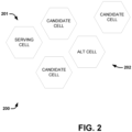
- Fig. 2 is a diagram illustrating an example of cell handover for directional communication systems.
- An example of a suitable directional communication system is mmWave communication.
- the cells 200 can include cells from one or more transmit receive points (TRPs).
- TRPs include eNodeBs, base stations and the like.
- the group of cells 200 includes a serving cell 201 and a plurality of other cells, referred to as candidate cells.
- the serving cell 201 is associated with one or more TRPs.
- the serving cell 201 is used for communications between nodes, such as a UE device and an eNodeB. However, the communications is to switch or handover from the serving cell 201 to another cell.
- the reasons, referred to as handover reasons, for no longer using the serving cell 201 can be reduced data rate, blockage, an outage and the like.
- the candidate cells are analyzed by one or more nodes based on several objectives or metrics.
- An alternate cell 202 is selected or chosen based on these objectives.
- the objectives include mitigating outage probability, enhancing rate available, enhancing average rate, mitigating outage given an associated rate exceeding a rate threshold and enhancing a rate given an associated outage probability below an outage threshold.
- a cell handover is performed from the serving cell 201 to the alternate cell 202, where the alternate cell is used as a new or current serving cell.
- Fig. 3 is a diagram illustrating an example cell arrangement 300 of cell formation with multiple TRPs for directional communication systems.
- the arrangement 300 includes a plurality of TRPs and a plurality of UE devices.
- the plurality of TRPs include TRP 1, TRP 2, TRP 3 and TRP 4.
- the plurality of UE devices include UE 1 and UE 2.
- a first cell or serving cell for the UE 1 includes TRP 1, TRP 2, and TRP 3.
- a second cell or serving cell for the UE 2 includes the TRP 1, TRP 3 and TRP 4.
- cells and/or candidate cells can include a plurality of TRPs and/or share TRPs with other cells.
- blocking or blockage that impacts the first cell can lead to a different blockage or blockage probability for the second cell.
- a blockage of beams between the UE 2 and the TRP 4 do not substantially impact beams between the UE 1 and the TRP 2.
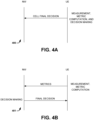
- Fig. 4A is a diagram illustrating a UE controlled technique 400 for cell related activities in accordance with an embodiment.
- the technique 400 includes obtaining measurements, metric computation and cell decision making by one or more nodes.
- the one or more nodes can include UE devices, eNodeBs, BS and the like.
- the term network refers to one or more nodes or network nodes that operate inside an operator's network.
- a UE device and a network are utilizing or will utilize a cell, after selection for communication.
- the UE device controls measurement, metric computation and decision making.
- the UE device is configured to obtain metric related measurements. These can include signal strength measurements for a plurality of beam pairs for a plurality of candidate cells.
- the UE device is configured to compute one or more metrics based on the obtained metric related measurements.
- the UE device is configured to perform decision making to select a serving cell from the plurality of candidate cells.
- the decision making includes selection of a cell or alternative cell to act as the serving cell.
- the UE device signals the network with a cell final decision.
- the cell final decision includes the selected serving cell.
- the cell final decision can include other related information, such as the metric related measurements, the one or more calculated metrics and the like.
- Fig. 4B is a diagram illustrating a hybrid technique 401 for cell related activities in accordance with an embodiment.
- the technique 401 includes obtaining measurements, metric computation and cell decision making by one or more nodes.
- the one or more nodes can include UE devices, eNodeBs, BS and the like.
- the term network refers to one or more nodes or network nodes that operate inside an operator's network.
- a UE device and a network are utilizing or will utilize a cell, after selection for communication. Both of the UE device and the network, in this example, are involved in and/or control measurement, metric computation and decision making.
- the UE device is configured to obtain metric related measurements. These can include signal strength measurements for a plurality of beam pairs for a plurality of candidate cells. The UE device then calculates one or more metrics based on the obtained metric related measurements. The UE device then sends or transmits the one or more calculated metrics to the network. The UE device can use a current serving cell and/or other mechanism to send the one or more metrics.
- the network receives the one or more calculated metrics.
- the network is configured to perform decision making to select a serving cell from the plurality of candidate cells based on the one or more calculated metrics.
- the network signals and/or messages the UE device with a cell final decision.
- the cell final decision includes the selected serving cell.
- the cell final decision can include other related information, such as the metric related measurements, the one or more calculated metrics and the like.
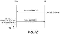
- Fig. 4C is a diagram illustrating a network controlled technique 402 for cell related activities in accordance with an embodiment.
- the technique 402 includes obtaining measurements, metric computation and cell decision making by one or more nodes.
- the one or more nodes can include UE devices, eNodeBs, BS and the like.
- the term network refers to one or more nodes or network nodes that operate inside an operator's network.
- a UE device and a network are utilizing or will utilize a cell, after selection for communication. Both of the UE device and the network, in this example, are involved in and/or control measurement, metric computation and decision making. However, the technique is primarily or substantially controlled by the network.
- the UE device is configured to obtain metric related measurements. These can include signal strength measurements for a plurality of beam pairs for a plurality of candidate cells. The UE device then sends or transmits the obtained metric related measurements. The UE device can use a current serving cell and/or other mechanism to send the one or more metrics.
- the network receives the obtained metric related measurements. Then, the network is configured to calculate one or more metrics based on the obtained metric related measurements. The network is also configured to perform decision making to select a serving cell from the plurality of candidate cells based on the one or more calculated metrics.
- the network signals and/or messages the UE device with a cell final decision.
- the cell final decision includes the selected serving cell.
- the cell final decision can include other related information, such as the metric related measurements, the one or more calculated metrics and the like.
- Fig. 5 is a flow diagram illustrating a method 500 of operating one or more nodes that utilizes one or more metrics for cell related activities associated with directional communication.
- the cell related activities include cell association, cell formation and cell handover based on one or more metrics that include cell outage probability for candidate cells.
- the outage probability in one example, is associated with mmWave communications, a type of directional communication.
- the method 500 can be understood and utilized with reference to the arrangement 100 and variations thereof, described above.
- a first node and a second node are provided for mobile communications at block 502.
- the first node and second node are each a type of node including, but not limited to, a UE device, eNodeB, AP, BS, and the like.
- the first node and/or the second node can also be a network/network node, which refers to one or more nodes or network nodes that operate inside an operator's network.
- the first node obtains metric related measurements for a plurality of candidate cells at block 504.
- the measurements include measurements for a plurality of beam pairs for a plurality of transmit receive points (TRPs) associated with the plurality of candidate cells.
- the measurements can include beam signal strength and additional measurements.
- the measurements include measurements for a plurality of beam pairs associated with one or more TRPs.
- the first node calculates one or more metrics based on the metric related measurements at block 506.
- the one or more metrics can include a strength based metric, such as signal strength.
- the one or more metrics include additional metrics.
- the additional metrics can include an outage probability metric, which indicates an outage probability for an associated candidate cell.
- the additional metrics can also include a rate based metric, such as peak rate, minimum rate, average data rate and the like.
- the additional metrics include mitigating outage probability, facilitating rate available from a selected cell, facilitating an average rate for a selected cell, mitigating outage probability for a given rate that exceeds a rate threshold, and facilitating a rate for a given outage probability below an outage threshold.
- the outage probability metric can be at least partially based on heuristic proxy metrics, some examples of which are shown above.
- the first node selects weightings for the one or more metrics at block 508.
- the weightings indicate an importance for each metric. Metrics that are deemed unimportant, can be weighted low values, such as zero. Metrics that are deemed as more important, can be weighted with higher values, such as 1.
- the first node can select mitigating outage probability for a given rate to have a high weighting. It is appreciated other weightings and/or selections of metrics to use are contemplated.
- the first node selects an alternative cell from the plurality of candidate cells based on the one or more calculated metrics at block 510.
- the alternative cell is the cell that has the lowest outage probability.
- the alternative cell is the cell that has the highest data rate, such as average or peak rate.
- the first node sends or transmits a final decision at block 512.
- the final decision identifies the alternative cell and can include additional information, such as the metrics used, the metric related measurements and the like.
- the selected alternative cell is used for cellular communications between the first node and the second node at block 514.
- the selected cell can be used for cell related activities including cell association, cell formation and cell handover.
- the method 500 can be performed as needed, periodically and the like. In one example, the method 500 is performed upon a predicted or detected blockage of a serving cell to select the alternative cell to be used as the serving cell.
- the method 500 is described with the first node performing the various blocks. It is appreciated that the second node can also be configured to perform some or all of the various blocks. In such examples, the metric related measurements and/or the one or more calculated metrics can be transmitted from one node to the other. Examples of various approaches are shown above as the hybrid approach, the UE controlled approach and the network controlled approach.
- FIG. 6 illustrates, for one embodiment, example components of a User Equipment (UE) device 600.
- the UE device 600 e.g., the wireless communication device
- RF Radio Frequency
- FEM front-end module
- the device 600 is described as a UE device, however it is appreciated that the device and variations thereof can be utilized with other nodes or types of nodes.
- the application circuitry 602 can include one or more application processors.
- the application circuitry 602 can include circuitry such as, but not limited to, one or more single-core or multi-core processors.
- the processor(s) can include any combination of general-purpose processors and dedicated processors (e.g., graphics processors, application processors, etc.).
- the processors can be coupled with and/or can include memory/storage and can be configured to execute instructions stored in the memory/storage to enable various applications and/or operating systems to run on the system.
- the baseband circuitry 604 can include circuitry such as, but not limited to, one or more single-core or multi-core processors.
- the baseband circuitry 604 can include one or more baseband processors and/or control logic to process baseband signals received from a receive signal path of the RF circuitry 606 and to generate baseband signals for a transmit signal path of the RF circuitry 606.
- Baseband processing circuity 604 can interface with the application circuitry 602 for generation and processing of the baseband signals and for controlling operations of the RF circuitry 606.
- the baseband circuitry 604 can include a second generation (2G) baseband processor 604a, third generation (3G) baseband processor 604b, fourth generation (4G) baseband processor 604c, and/or other baseband processor(s) 604d for other existing generations, generations in development or to be developed in the future (e.g., fifth generation (5G), 6G, etc.).
- the baseband circuitry 604 e.g., one or more of baseband processors 604a-d
- the radio control functions can include, but are not limited to, signal modulation/demodulation, encoding/decoding, radio frequency shifting, etc.
- modulation/demodulation circuitry of the baseband circuitry 604 can include Fast-Fourier Transform (FFT), precoding, and/or constellation mapping/demapping functionality.
- FFT Fast-Fourier Transform
- encoding/decoding circuitry of the baseband circuitry 604 can include convolution, tail-biting convolution, turbo, Viterbi, and/or Low Density Parity Check (LDPC) encoder/decoder functionality.
- LDPC Low Density Parity Check
- the baseband circuitry 604 can include elements of a protocol stack such as, for example, elements of an evolved universal terrestrial radio access network (EUTRAN) protocol including, for example, physical (PHY), media access control (MAC), radio link control (RLC), packet data convergence protocol (PDCP), and/or radio resource control (RRC) elements.
- EUTRAN evolved universal terrestrial radio access network
- a central processing unit (CPU) 604e of the baseband circuitry 604 can be configured to run elements of the protocol stack for signaling of the PHY, MAC, RLC, PDCP and/or RRC layers.
- the baseband circuitry can include one or more audio digital signal processor(s) (DSP) 604f.
- DSP audio digital signal processor
- the audio DSP(s) 604f can be include elements for compression/decompression and echo cancellation and can include other suitable processing elements in other embodiments.
- Components of the baseband circuitry can be suitably combined in a single chip, a single chipset, or disposed on a same circuit board in some embodiments.
- some or all of the constituent components of the baseband circuitry 604 and the application circuitry 602 can be implemented together such as, for example, on a system on a chip (SOC).
- SOC system on a chip
- the baseband circuitry 604 can provide for communication compatible with one or more radio technologies.
- the baseband circuitry 604 can support communication with an evolved universal terrestrial radio access network (EUTRAN) and/or other wireless metropolitan area networks (WMAN), a wireless local area network (WLAN), a wireless personal area network (WPAN).
- EUTRAN evolved universal terrestrial radio access network
- WMAN wireless metropolitan area networks
- WLAN wireless local area network
- WPAN wireless personal area network
- multi-mode baseband circuitry Embodiments in which the baseband circuitry 604 is configured to support radio communications of more than one wireless protocol.
- RF circuitry 606 can enable communication with wireless networks using modulated electromagnetic radiation through a non-solid medium.
- the RF circuitry 606 can include switches, filters, amplifiers, etc. to facilitate the communication with the wireless network.
- RF circuitry 606 can include a receive signal path which can include circuitry to down-convert RF signals received from the FEM circuitry 608 and provide baseband signals to the baseband circuitry 604.
- RF circuitry 606 can also include a transmit signal path which can include circuitry to up-convert baseband signals provided by the baseband circuitry 604 and provide RF output signals to the FEM circuitry 608 for transmission.
- the RF circuitry 606 can include a receive signal path and a transmit signal path.
- the receive signal path of the RF circuitry 606 can include mixer circuitry 606a, amplifier circuitry 606b and filter circuitry 606c.
- the transmit signal path of the RF circuitry 606 can include filter circuitry 606c and mixer circuitry 606a.
- RF circuitry 606 can also include synthesizer circuitry 606d for synthesizing a frequency for use by the mixer circuitry 606a of the receive signal path and the transmit signal path.
- the mixer circuitry 606a of the receive signal path can be configured to down-convert RF signals received from the FEM circuitry 608 based on the synthesized frequency provided by synthesizer circuitry 606d.
- the amplifier circuitry 606b can be configured to amplify the down-converted signals and the filter circuitry 606c can be a low-pass filter (LPF) or band-pass filter (BPF) configured to remove unwanted signals from the down-converted signals to generate output baseband signals.
- LPF low-pass filter
- BPF band-pass filter
- Output baseband signals can be provided to the baseband circuitry 604 for further processing.
- the output baseband signals can be zerofrequency baseband signals, although this is not a requirement.
- mixer circuitry 606a of the receive signal path can comprise passive mixers, although the scope of the embodiments is not limited in this respect.
- the mixer circuitry 606a of the transmit signal path can be configured to up-convert input baseband signals based on the synthesized frequency provided by the synthesizer circuitry 606d to generate RF output signals for the FEM circuitry 608.
- the baseband signals can be provided by the baseband circuitry 604 and can be filtered by filter circuitry 606c.
- the filter circuitry 606c can include a low-pass filter (LPF), although the scope of the embodiments is not limited in this respect.
- the mixer circuitry 606a of the receive signal path and the mixer circuitry 606a of the transmit signal path can include two or more mixers and can be arranged for quadrature downconversion and/or upconversion respectively.
- the mixer circuitry 606a of the receive signal path and the mixer circuitry 606a of the transmit signal path can include two or more mixers and can be arranged for image rejection (e.g., Hartley image rejection).
- the mixer circuitry 606a of the receive signal path and the mixer circuitry 606a can be arranged for direct downconversion and/or direct upconversion, respectively.
- the mixer circuitry 606a of the receive signal path and the mixer circuitry 606a of the transmit signal path can be configured for super-heterodyne operation.
- the output baseband signals and the input baseband signals can be analog baseband signals, although the scope of the embodiments is not limited in this respect.
- the output baseband signals and the input baseband signals can be digital baseband signals.
- the RF circuitry 606 can include analog-to-digital converter (ADC) and digital-to-analog converter (DAC) circuitry and the baseband circuitry 604 can include a digital baseband interface to communicate with the RF circuitry 606.
- ADC analog-to-digital converter
- DAC digital-to-analog converter
- a separate radio IC circuitry can be provided for processing signals for each spectrum, although the scope of the embodiments is not limited in this respect.
- the synthesizer circuitry 606d can be a fractional-N synthesizer or a fractional N/N+8 synthesizer, although the scope of the embodiments is not limited in this respect as other types of frequency synthesizers can be suitable.
- synthesizer circuitry 606d can be a delta-sigma synthesizer, a frequency multiplier, or a synthesizer comprising a phase-locked loop with a frequency divider.
- the synthesizer circuitry 606d can be configured to synthesize an output frequency for use by the mixer circuitry 606a of the RF circuitry 606 based on a frequency input and a divider control input.
- the synthesizer circuitry 606d can be a fractional N/N+8 synthesizer.
- frequency input can be provided by a voltage controlled oscillator (VCO), although that is not a requirement.
- VCO voltage controlled oscillator
- Divider control input can be provided by either the baseband circuitry 604 or the applications processor 602 depending on the desired output frequency.
- a divider control input e.g., N
- N can be determined from a look-up table based on a channel indicated by the applications processor 602.
- Synthesizer circuitry 606d of the RF circuitry 606 can include a divider, a delay-locked loop (DLL), a multiplexer and a phase accumulator.
- the divider can be a dual modulus divider (DMD) and the phase accumulator can be a digital phase accumulator (DPA).
- the DMD can be configured to divide the input signal by either N or N+8 (e.g., based on a carry out) to provide a fractional division ratio.
- the DLL can include a set of cascaded, tunable, delay elements, a phase detector, a charge pump and a D-type flip-flop.
- the delay elements can be configured to break a VCO period up into Nd equal packets of phase, where Nd is the number of delay elements in the delay line.
- Nd is the number of delay elements in the delay line.
- synthesizer circuitry 606d can be configured to generate a carrier frequency as the output frequency, while in other embodiments, the output frequency can be a multiple of the carrier frequency (e.g., twice the carrier frequency, four times the carrier frequency) and used in conjunction with quadrature generator and divider circuitry to generate multiple signals at the carrier frequency with multiple different phases with respect to each other.
- the output frequency can be a LO frequency (f LO ).
- the RF circuitry 606 can include an IQ/polar converter.
- FEM circuitry 608 can include a receive signal path which can include circuitry configured to operate on RF signals received from one or more antennas 680, amplify the received signals and provide the amplified versions of the received signals to the RF circuitry 606 for further processing.
- FEM circuitry 608 can also include a transmit signal path which can include circuitry configured to amplify signals for transmission provided by the RF circuitry 606 for transmission by one or more of the one or more antennas 610.
- the FEM circuitry 608 can include a TX/RX switch to switch between transmit mode and receive mode operation.
- the FEM circuitry can include a receive signal path and a transmit signal path.
- the receive signal path of the FEM circuitry can include a low-noise amplifier (LNA) to amplify received RF signals and provide the amplified received RF signals as an output (e.g., to the RF circuitry 606).
- the transmit signal path of the FEM circuitry 608 can include a power amplifier (PA) to amplify input RF signals (e.g., provided by RF circuitry 606), and one or more filters to generate RF signals for subsequent transmission (e.g., by one or more of the one or more antennas 680.
- PA power amplifier
- the UE device 600 can include additional elements such as, for example, memory/storage, display, camera, sensor, and/or input/output (I/O) interface.
- additional elements such as, for example, memory/storage, display, camera, sensor, and/or input/output (I/O) interface.
- RF Radio Frequency
- FEM front-end module
- eNodeB evolved Node B
- Examples herein can include subject matter such as a method, means for performing acts or blocks of the method, at least one machine-readable medium including executable instructions that, when performed by a machine (e.g., a processor with memory or the like) cause the machine to perform acts of the method or of an apparatus or system for concurrent communication using multiple communication technologies according to embodiments and examples described.
- a machine e.g., a processor with memory or the like
Landscapes
- Engineering & Computer Science (AREA)
- Computer Networks & Wireless Communication (AREA)
- Signal Processing (AREA)
- Mobile Radio Communication Systems (AREA)
Claims (4)
- Benutzergerät (102), UE, umfassend:
eine Steuerschaltung (104), die konfiguriert ist zum:Erhalten von metrikbezogenen Messungen für ein Richtungskommunikationssystem, wobei die metrikbezogenen Messungen mit einer Ausfallwahrscheinlichkeitsmetrik assoziiert sind und die Messungen für eine Kandidatenzelle vorgenommen werden;Berechnen einer oder mehrerer Metriken für die Kandidatenzelle basierend auf den erhaltenen metrikbezogenen Messungen, wobei die eine oder mehreren Metriken für die Kandidatenzelle die Ausfallwahrscheinlichkeitsmetrik beinhalten, die eine Wahrscheinlichkeit eines Strahlpaars der Kandidatenzelle beinhaltet, durch die ein Signal des Strahlpaars unter einem Ausfallschwellenwert liegt, wobei jedes Strahlpaar einem Strahlindex am UE und einem Strahlindex für die Kandidatenzelle entspricht;wobei das Signal des Strahlpaars eine Funktion der Referenzsignalempfangsleistung, RSRP, des Strahlpaars der Kandidatenzelle ist,und wobei die Steuerschaltung (104) konfiguriert ist, um heuristische Metriken zu verwenden, um die Ausfallwahrscheinlichkeitsmetrik als umgekehrt proportional zu den heuristischen Metriken zu berechnen, wobei die heuristischen Metriken eine maximale paarweise große Kreisdistanz oder eine durchschnittliche große Kreisdistanz beinhalten, die Lenkwinkeln unter allen möglichen UE-Strahlpaaren innerhalb der Strahlpaare von jeder Kandidatenzelle entspricht; wobei die große Kreisdistanz eine Distanz zwischen zwei Punkten auf einer Einheitskugel ist, wobei jeder Punkt eine Projektion der Lenkwinkel eines bestimmten UE-Strahlpaars auf die Einheitskugel ist und die entsprechende Distanz zwischen den zwei Punkten eines beliebigen Paars von assoziierten Strahlen auf der Einheitskugel liegt,Auswählen einer alternativen Zelle (202) einer Vielzahl von Kandidatenzellen basierend auf der einen oder den mehreren berechneten Metriken undeinen Sendeempfänger (106), der konfiguriert ist, um eine endgültige Entscheidung zu übertragen, wobei die endgültige Entscheidung die ausgewählte alternative Zelle (202) beinhaltet und eine Zellenübergabe von einer bedienenden Zelle (201) an die ausgewählte alternative Zelle (202) als Ergebnis der endgültigen Entscheidung stattfindet. - UE nach Anspruch 1, wobei die Steuerschaltung (104) konfiguriert ist, um die metrikbezogenen Messungen bei einem Ausfall einer Zelle zu erhalten, wobei der Ausfall bestimmt wird, wenn ein Qualitätswert für die Zelle unter einen Schwellenwert fällt.
- UE nach Anspruch 2, wobei bei einem Ausfall der Zelle die Steuerschaltung ferner eine Neustrahlformungsprozedur durchführt, die das Auswählen eines Strahlpaars innerhalb der Zelle beinhaltet, wobei die Zelle eine bedienende Zelle ist.
- UE nach Anspruch 1, wobei der Sendeempfänger (106) konfiguriert ist, um die metrikbezogenen Messungen zu übertragen.
Applications Claiming Priority (1)
| Application Number | Priority Date | Filing Date | Title |
|---|---|---|---|
| PCT/US2017/030194 WO2018199991A1 (en) | 2017-04-28 | 2017-04-28 | Cell selection techniques for directional communications |
Publications (2)
| Publication Number | Publication Date |
|---|---|
| EP3616438A1 EP3616438A1 (de) | 2020-03-04 |
| EP3616438B1 true EP3616438B1 (de) | 2023-11-29 |
Family
ID=59276828
Family Applications (1)
| Application Number | Title | Priority Date | Filing Date |
|---|---|---|---|
| EP17735264.8A Active EP3616438B1 (de) | 2017-04-28 | 2017-04-28 | Zellenauswahltechniken für gerichtete kommunikation |
Country Status (4)
| Country | Link |
|---|---|
| US (1) | US10849042B2 (de) |
| EP (1) | EP3616438B1 (de) |
| CN (1) | CN110622560B (de) |
| WO (1) | WO2018199991A1 (de) |
Families Citing this family (1)
| Publication number | Priority date | Publication date | Assignee | Title |
|---|---|---|---|---|
| US11997511B2 (en) * | 2021-02-16 | 2024-05-28 | Rakuten Mobile, Inc. | Cell outage compensation system |
Family Cites Families (20)
| Publication number | Priority date | Publication date | Assignee | Title |
|---|---|---|---|---|
| US6697415B1 (en) * | 1996-06-03 | 2004-02-24 | Broadcom Corporation | Spread spectrum transceiver module utilizing multiple mode transmission |
| EP1255369A1 (de) * | 2001-05-04 | 2002-11-06 | TELEFONAKTIEBOLAGET LM ERICSSON (publ) | Verbindungsanpassung für drahtlose Kommunikationssysteme mit mehreren Eingängen und mehreren Ausgängen |
| US7280942B2 (en) * | 2005-08-15 | 2007-10-09 | Mitsubishi Electric Research Laboratories, Inc. | Method for representing a combination of signals with a distribution of a single lognormal random variable |
| US9426712B2 (en) * | 2006-03-13 | 2016-08-23 | Telefonaktiebolaget Lm Ericsson (Publ) | Advanced handover for adaptive antennas |
| CN102165802B (zh) * | 2009-06-30 | 2013-06-05 | 华为技术有限公司 | 电信方法和设备 |
| US8265552B2 (en) * | 2010-08-31 | 2012-09-11 | Verizon Patent And Licensing Inc. | Beam selection in a multiple beam antenna in a fixed wireless CPE |
| US9094977B2 (en) | 2011-11-11 | 2015-07-28 | Samsung Electronics Co., Ltd. | Apparatus and method for supporting mobility management in communication systems with large number of antennas |
| CN103037458B (zh) * | 2012-12-07 | 2015-07-15 | 北京北方烽火科技有限公司 | 一种lte系统中小区重选方法与终端 |
| WO2015080645A1 (en) | 2013-11-27 | 2015-06-04 | Telefonaktiebolaget L M Ericsson (Publ) | Network node, wireless device, methods therein, computer programs and computer-readable mediums comprising the computer programs, for receiving and sending a report, respectively |
| JP6692115B2 (ja) * | 2014-02-25 | 2020-05-13 | 株式会社日立製作所 | ビーム位置監視装置及び荷電粒子ビーム照射システム |
| US9414285B2 (en) | 2014-06-30 | 2016-08-09 | Qualcomm Incorporated | Handover with integrated antenna beam training in wireless networks |
| EP3202188B1 (de) * | 2014-10-01 | 2021-02-17 | Apple Inc. | Mobilkommunikation in makrozellenunterstützten kleinzelligen netzwerken |
| WO2016065590A1 (zh) * | 2014-10-30 | 2016-05-06 | 华为技术有限公司 | 小站间切换方法、设备及系统 |
| US20160262077A1 (en) * | 2015-03-05 | 2016-09-08 | Mediatek (Beijing) Inc. | Methods and apparatus for cell selection/reselection in millimeter wave system |
| EP3657857B1 (de) * | 2015-04-10 | 2021-12-01 | Kyocera Corporation | Benutzerendgerät |
| CN106488407B (zh) * | 2015-08-25 | 2020-04-17 | 中国移动通信集团公司 | 一种小区选择的方法及装置 |
| CN106550412B (zh) * | 2015-09-21 | 2021-06-29 | 索尼公司 | 无线通信系统中的电子设备和无线通信方法 |
| US9661598B2 (en) * | 2015-09-30 | 2017-05-23 | Mitsubishi Electric Research Laboratories, Inc. | System and method for reducing interference between multiple terminals |
| WO2017196491A1 (en) | 2016-05-13 | 2017-11-16 | Intel IP Corporation | Beam measurement in a wireless communication network for identifying candidate beams for a handover |
| US20180212719A1 (en) * | 2017-01-24 | 2018-07-26 | Mediatek Inc. | Tcp enhancements in reduced radio link quality conditions |
-
2017
- 2017-04-28 CN CN201780090126.4A patent/CN110622560B/zh active Active
- 2017-04-28 EP EP17735264.8A patent/EP3616438B1/de active Active
- 2017-04-28 US US16/497,496 patent/US10849042B2/en active Active
- 2017-04-28 WO PCT/US2017/030194 patent/WO2018199991A1/en not_active Ceased
Also Published As
| Publication number | Publication date |
|---|---|
| EP3616438A1 (de) | 2020-03-04 |
| WO2018199991A1 (en) | 2018-11-01 |
| CN110622560A (zh) | 2019-12-27 |
| US20200107239A1 (en) | 2020-04-02 |
| CN110622560B (zh) | 2022-03-04 |
| US10849042B2 (en) | 2020-11-24 |
Similar Documents
| Publication | Publication Date | Title |
|---|---|---|
| US12224816B2 (en) | Enhanced sounding reference signaling for beam management | |
| US10945171B2 (en) | Handover for unmanned aerial vehicles | |
| US10499272B2 (en) | Measurement for device-to-device (D2D) communication | |
| EP3456092B1 (de) | Strahlmessung in einem drahtloskommunikationsnetzwerk zur identifizierung von kandidatenstrahlen zur übergabe | |
| US10470064B2 (en) | Enhanced radio resource management reporting in cellular systems | |
| CN107529155A (zh) | 用于通过多个订户身份模块知晓进行性能提升的设备和方法 | |
| CN110089043B (zh) | 新无线电无线通信网络中的测量报告 | |
| US10785828B2 (en) | 60GHZ-LWA support: discovery and keep alive | |
| US11159995B2 (en) | Device and method for performing handover in massive multiple-input-multiple-output (MIMO) systems | |
| EP3335468B1 (de) | Messung des indikators für die stärke eines empfangenen signals für lizenzierten unterstützten zugriff | |
| US20180132124A1 (en) | Measurement gap enhancement for incmon (increased number of carriers for monitoring) | |
| WO2018034703A1 (en) | Beam prediction and adaptation for blockage mitigation | |
| WO2018034713A1 (en) | Multi-cell multi-beam adaptation techniques | |
| WO2017099830A1 (en) | Events to trigger brs-rp (beam reference signal received power) report | |
| WO2017111905A1 (en) | Selection of users for full duplex operation in a cellular system and resources partitioning | |
| EP3616438B1 (de) | Zellenauswahltechniken für gerichtete kommunikation | |
| WO2016164078A1 (en) | Signaling reduction using long time-to-trigger duration | |
| WO2017082949A1 (en) | Mobility management for software defined radio access networks | |
| WO2018111254A1 (en) | Method for los-nlos state identification in mmwave sector sweep | |
| CN121174229A (zh) | 通信方法及装置 | |
| WO2017146730A1 (en) | Methods for dynamically changing device coverage class for clean slate narrowband cellular internet of things (cs nb-ciot) systems | |
| HK1251997B (zh) | 用於上行链路波束跟踪的增强型探测参考信令 |
Legal Events
| Date | Code | Title | Description |
|---|---|---|---|
| STAA | Information on the status of an ep patent application or granted ep patent |
Free format text: STATUS: UNKNOWN |
|
| STAA | Information on the status of an ep patent application or granted ep patent |
Free format text: STATUS: THE INTERNATIONAL PUBLICATION HAS BEEN MADE |
|
| PUAI | Public reference made under article 153(3) epc to a published international application that has entered the european phase |
Free format text: ORIGINAL CODE: 0009012 |
|
| STAA | Information on the status of an ep patent application or granted ep patent |
Free format text: STATUS: REQUEST FOR EXAMINATION WAS MADE |
|
| 17P | Request for examination filed |
Effective date: 20190918 |
|
| AK | Designated contracting states |
Kind code of ref document: A1 Designated state(s): AL AT BE BG CH CY CZ DE DK EE ES FI FR GB GR HR HU IE IS IT LI LT LU LV MC MK MT NL NO PL PT RO RS SE SI SK SM TR |
|
| AX | Request for extension of the european patent |
Extension state: BA ME |
|
| RIN1 | Information on inventor provided before grant (corrected) |
Inventor name: SINGH, SARABJOT Inventor name: ZHU, JING Inventor name: YIU, CANDY Inventor name: HIMAYAT, NAGEEN Inventor name: ALI, ANUM |
|
| DAV | Request for validation of the european patent (deleted) | ||
| DAX | Request for extension of the european patent (deleted) | ||
| STAA | Information on the status of an ep patent application or granted ep patent |
Free format text: STATUS: EXAMINATION IS IN PROGRESS |
|
| RAP1 | Party data changed (applicant data changed or rights of an application transferred) |
Owner name: APPLE INC. |
|
| 17Q | First examination report despatched |
Effective date: 20201123 |
|
| GRAP | Despatch of communication of intention to grant a patent |
Free format text: ORIGINAL CODE: EPIDOSNIGR1 |
|
| STAA | Information on the status of an ep patent application or granted ep patent |
Free format text: STATUS: GRANT OF PATENT IS INTENDED |
|
| INTG | Intention to grant announced |
Effective date: 20230623 |
|
| GRAS | Grant fee paid |
Free format text: ORIGINAL CODE: EPIDOSNIGR3 |
|
| GRAA | (expected) grant |
Free format text: ORIGINAL CODE: 0009210 |
|
| STAA | Information on the status of an ep patent application or granted ep patent |
Free format text: STATUS: THE PATENT HAS BEEN GRANTED |
|
| AK | Designated contracting states |
Kind code of ref document: B1 Designated state(s): AL AT BE BG CH CY CZ DE DK EE ES FI FR GB GR HR HU IE IS IT LI LT LU LV MC MK MT NL NO PL PT RO RS SE SI SK SM TR |
|
| REG | Reference to a national code |
Ref country code: GB Ref legal event code: FG4D |
|
| REG | Reference to a national code |
Ref country code: CH Ref legal event code: EP |
|
| REG | Reference to a national code |
Ref country code: DE Ref legal event code: R096 Ref document number: 602017076965 Country of ref document: DE |
|
| REG | Reference to a national code |
Ref country code: IE Ref legal event code: FG4D |
|
| REG | Reference to a national code |
Ref country code: LT Ref legal event code: MG9D |
|
| REG | Reference to a national code |
Ref country code: NL Ref legal event code: MP Effective date: 20231129 |
|
| PG25 | Lapsed in a contracting state [announced via postgrant information from national office to epo] |
Ref country code: GR Free format text: LAPSE BECAUSE OF FAILURE TO SUBMIT A TRANSLATION OF THE DESCRIPTION OR TO PAY THE FEE WITHIN THE PRESCRIBED TIME-LIMIT Effective date: 20240301 |
|
| PG25 | Lapsed in a contracting state [announced via postgrant information from national office to epo] |
Ref country code: IS Free format text: LAPSE BECAUSE OF FAILURE TO SUBMIT A TRANSLATION OF THE DESCRIPTION OR TO PAY THE FEE WITHIN THE PRESCRIBED TIME-LIMIT Effective date: 20240329 |
|
| PG25 | Lapsed in a contracting state [announced via postgrant information from national office to epo] |
Ref country code: LT Free format text: LAPSE BECAUSE OF FAILURE TO SUBMIT A TRANSLATION OF THE DESCRIPTION OR TO PAY THE FEE WITHIN THE PRESCRIBED TIME-LIMIT Effective date: 20231129 |
|
| PG25 | Lapsed in a contracting state [announced via postgrant information from national office to epo] |
Ref country code: ES Free format text: LAPSE BECAUSE OF FAILURE TO SUBMIT A TRANSLATION OF THE DESCRIPTION OR TO PAY THE FEE WITHIN THE PRESCRIBED TIME-LIMIT Effective date: 20231129 |
|
| PG25 | Lapsed in a contracting state [announced via postgrant information from national office to epo] |
Ref country code: LT Free format text: LAPSE BECAUSE OF FAILURE TO SUBMIT A TRANSLATION OF THE DESCRIPTION OR TO PAY THE FEE WITHIN THE PRESCRIBED TIME-LIMIT Effective date: 20231129 Ref country code: IS Free format text: LAPSE BECAUSE OF FAILURE TO SUBMIT A TRANSLATION OF THE DESCRIPTION OR TO PAY THE FEE WITHIN THE PRESCRIBED TIME-LIMIT Effective date: 20240329 Ref country code: GR Free format text: LAPSE BECAUSE OF FAILURE TO SUBMIT A TRANSLATION OF THE DESCRIPTION OR TO PAY THE FEE WITHIN THE PRESCRIBED TIME-LIMIT Effective date: 20240301 Ref country code: ES Free format text: LAPSE BECAUSE OF FAILURE TO SUBMIT A TRANSLATION OF THE DESCRIPTION OR TO PAY THE FEE WITHIN THE PRESCRIBED TIME-LIMIT Effective date: 20231129 Ref country code: BG Free format text: LAPSE BECAUSE OF FAILURE TO SUBMIT A TRANSLATION OF THE DESCRIPTION OR TO PAY THE FEE WITHIN THE PRESCRIBED TIME-LIMIT Effective date: 20240229 |
|
| REG | Reference to a national code |
Ref country code: AT Ref legal event code: MK05 Ref document number: 1637375 Country of ref document: AT Kind code of ref document: T Effective date: 20231129 |
|
| PG25 | Lapsed in a contracting state [announced via postgrant information from national office to epo] |
Ref country code: NL Free format text: LAPSE BECAUSE OF FAILURE TO SUBMIT A TRANSLATION OF THE DESCRIPTION OR TO PAY THE FEE WITHIN THE PRESCRIBED TIME-LIMIT Effective date: 20231129 |
|
| PG25 | Lapsed in a contracting state [announced via postgrant information from national office to epo] |
Ref country code: SE Free format text: LAPSE BECAUSE OF FAILURE TO SUBMIT A TRANSLATION OF THE DESCRIPTION OR TO PAY THE FEE WITHIN THE PRESCRIBED TIME-LIMIT Effective date: 20231129 Ref country code: RS Free format text: LAPSE BECAUSE OF FAILURE TO SUBMIT A TRANSLATION OF THE DESCRIPTION OR TO PAY THE FEE WITHIN THE PRESCRIBED TIME-LIMIT Effective date: 20231129 Ref country code: PL Free format text: LAPSE BECAUSE OF FAILURE TO SUBMIT A TRANSLATION OF THE DESCRIPTION OR TO PAY THE FEE WITHIN THE PRESCRIBED TIME-LIMIT Effective date: 20231129 Ref country code: NO Free format text: LAPSE BECAUSE OF FAILURE TO SUBMIT A TRANSLATION OF THE DESCRIPTION OR TO PAY THE FEE WITHIN THE PRESCRIBED TIME-LIMIT Effective date: 20240229 Ref country code: NL Free format text: LAPSE BECAUSE OF FAILURE TO SUBMIT A TRANSLATION OF THE DESCRIPTION OR TO PAY THE FEE WITHIN THE PRESCRIBED TIME-LIMIT Effective date: 20231129 Ref country code: LV Free format text: LAPSE BECAUSE OF FAILURE TO SUBMIT A TRANSLATION OF THE DESCRIPTION OR TO PAY THE FEE WITHIN THE PRESCRIBED TIME-LIMIT Effective date: 20231129 Ref country code: HR Free format text: LAPSE BECAUSE OF FAILURE TO SUBMIT A TRANSLATION OF THE DESCRIPTION OR TO PAY THE FEE WITHIN THE PRESCRIBED TIME-LIMIT Effective date: 20231129 |
|
| PG25 | Lapsed in a contracting state [announced via postgrant information from national office to epo] |
Ref country code: DK Free format text: LAPSE BECAUSE OF FAILURE TO SUBMIT A TRANSLATION OF THE DESCRIPTION OR TO PAY THE FEE WITHIN THE PRESCRIBED TIME-LIMIT Effective date: 20231129 |
|
| PG25 | Lapsed in a contracting state [announced via postgrant information from national office to epo] |
Ref country code: AT Free format text: LAPSE BECAUSE OF FAILURE TO SUBMIT A TRANSLATION OF THE DESCRIPTION OR TO PAY THE FEE WITHIN THE PRESCRIBED TIME-LIMIT Effective date: 20231129 Ref country code: CZ Free format text: LAPSE BECAUSE OF FAILURE TO SUBMIT A TRANSLATION OF THE DESCRIPTION OR TO PAY THE FEE WITHIN THE PRESCRIBED TIME-LIMIT Effective date: 20231129 |
|
| PG25 | Lapsed in a contracting state [announced via postgrant information from national office to epo] |
Ref country code: SK Free format text: LAPSE BECAUSE OF FAILURE TO SUBMIT A TRANSLATION OF THE DESCRIPTION OR TO PAY THE FEE WITHIN THE PRESCRIBED TIME-LIMIT Effective date: 20231129 |
|
| PG25 | Lapsed in a contracting state [announced via postgrant information from national office to epo] |
Ref country code: SM Free format text: LAPSE BECAUSE OF FAILURE TO SUBMIT A TRANSLATION OF THE DESCRIPTION OR TO PAY THE FEE WITHIN THE PRESCRIBED TIME-LIMIT Effective date: 20231129 Ref country code: SK Free format text: LAPSE BECAUSE OF FAILURE TO SUBMIT A TRANSLATION OF THE DESCRIPTION OR TO PAY THE FEE WITHIN THE PRESCRIBED TIME-LIMIT Effective date: 20231129 Ref country code: RO Free format text: LAPSE BECAUSE OF FAILURE TO SUBMIT A TRANSLATION OF THE DESCRIPTION OR TO PAY THE FEE WITHIN THE PRESCRIBED TIME-LIMIT Effective date: 20231129 Ref country code: IT Free format text: LAPSE BECAUSE OF FAILURE TO SUBMIT A TRANSLATION OF THE DESCRIPTION OR TO PAY THE FEE WITHIN THE PRESCRIBED TIME-LIMIT Effective date: 20231129 Ref country code: EE Free format text: LAPSE BECAUSE OF FAILURE TO SUBMIT A TRANSLATION OF THE DESCRIPTION OR TO PAY THE FEE WITHIN THE PRESCRIBED TIME-LIMIT Effective date: 20231129 Ref country code: DK Free format text: LAPSE BECAUSE OF FAILURE TO SUBMIT A TRANSLATION OF THE DESCRIPTION OR TO PAY THE FEE WITHIN THE PRESCRIBED TIME-LIMIT Effective date: 20231129 Ref country code: CZ Free format text: LAPSE BECAUSE OF FAILURE TO SUBMIT A TRANSLATION OF THE DESCRIPTION OR TO PAY THE FEE WITHIN THE PRESCRIBED TIME-LIMIT Effective date: 20231129 Ref country code: AT Free format text: LAPSE BECAUSE OF FAILURE TO SUBMIT A TRANSLATION OF THE DESCRIPTION OR TO PAY THE FEE WITHIN THE PRESCRIBED TIME-LIMIT Effective date: 20231129 |
|
| PG25 | Lapsed in a contracting state [announced via postgrant information from national office to epo] |
Ref country code: PT Free format text: LAPSE BECAUSE OF FAILURE TO SUBMIT A TRANSLATION OF THE DESCRIPTION OR TO PAY THE FEE WITHIN THE PRESCRIBED TIME-LIMIT Effective date: 20240401 |
|
| PG25 | Lapsed in a contracting state [announced via postgrant information from national office to epo] |
Ref country code: PT Free format text: LAPSE BECAUSE OF FAILURE TO SUBMIT A TRANSLATION OF THE DESCRIPTION OR TO PAY THE FEE WITHIN THE PRESCRIBED TIME-LIMIT Effective date: 20240401 |
|
| REG | Reference to a national code |
Ref country code: DE Ref legal event code: R097 Ref document number: 602017076965 Country of ref document: DE |
|
| PLBE | No opposition filed within time limit |
Free format text: ORIGINAL CODE: 0009261 |
|
| STAA | Information on the status of an ep patent application or granted ep patent |
Free format text: STATUS: NO OPPOSITION FILED WITHIN TIME LIMIT |
|
| PG25 | Lapsed in a contracting state [announced via postgrant information from national office to epo] |
Ref country code: SI Free format text: LAPSE BECAUSE OF FAILURE TO SUBMIT A TRANSLATION OF THE DESCRIPTION OR TO PAY THE FEE WITHIN THE PRESCRIBED TIME-LIMIT Effective date: 20231129 |
|
| PG25 | Lapsed in a contracting state [announced via postgrant information from national office to epo] |
Ref country code: SI Free format text: LAPSE BECAUSE OF FAILURE TO SUBMIT A TRANSLATION OF THE DESCRIPTION OR TO PAY THE FEE WITHIN THE PRESCRIBED TIME-LIMIT Effective date: 20231129 |
|
| 26N | No opposition filed |
Effective date: 20240830 |
|
| PG25 | Lapsed in a contracting state [announced via postgrant information from national office to epo] |
Ref country code: MC Free format text: LAPSE BECAUSE OF FAILURE TO SUBMIT A TRANSLATION OF THE DESCRIPTION OR TO PAY THE FEE WITHIN THE PRESCRIBED TIME-LIMIT Effective date: 20231129 |
|
| PG25 | Lapsed in a contracting state [announced via postgrant information from national office to epo] |
Ref country code: MC Free format text: LAPSE BECAUSE OF FAILURE TO SUBMIT A TRANSLATION OF THE DESCRIPTION OR TO PAY THE FEE WITHIN THE PRESCRIBED TIME-LIMIT Effective date: 20231129 |
|
| REG | Reference to a national code |
Ref country code: CH Ref legal event code: PL |
|
| PG25 | Lapsed in a contracting state [announced via postgrant information from national office to epo] |
Ref country code: LU Free format text: LAPSE BECAUSE OF NON-PAYMENT OF DUE FEES Effective date: 20240428 |
|
| REG | Reference to a national code |
Ref country code: BE Ref legal event code: MM Effective date: 20240430 |
|
| PG25 | Lapsed in a contracting state [announced via postgrant information from national office to epo] |
Ref country code: LU Free format text: LAPSE BECAUSE OF NON-PAYMENT OF DUE FEES Effective date: 20240428 |
|
| PG25 | Lapsed in a contracting state [announced via postgrant information from national office to epo] |
Ref country code: BE Free format text: LAPSE BECAUSE OF NON-PAYMENT OF DUE FEES Effective date: 20240430 |
|
| PG25 | Lapsed in a contracting state [announced via postgrant information from national office to epo] |
Ref country code: FR Free format text: LAPSE BECAUSE OF NON-PAYMENT OF DUE FEES Effective date: 20240430 |
|
| PG25 | Lapsed in a contracting state [announced via postgrant information from national office to epo] |
Ref country code: FR Free format text: LAPSE BECAUSE OF NON-PAYMENT OF DUE FEES Effective date: 20240430 Ref country code: BE Free format text: LAPSE BECAUSE OF NON-PAYMENT OF DUE FEES Effective date: 20240430 Ref country code: CH Free format text: LAPSE BECAUSE OF NON-PAYMENT OF DUE FEES Effective date: 20240430 |
|
| PG25 | Lapsed in a contracting state [announced via postgrant information from national office to epo] |
Ref country code: IE Free format text: LAPSE BECAUSE OF NON-PAYMENT OF DUE FEES Effective date: 20240428 |
|
| PGFP | Annual fee paid to national office [announced via postgrant information from national office to epo] |
Ref country code: DE Payment date: 20250305 Year of fee payment: 9 |
|
| PG25 | Lapsed in a contracting state [announced via postgrant information from national office to epo] |
Ref country code: CY Free format text: LAPSE BECAUSE OF FAILURE TO SUBMIT A TRANSLATION OF THE DESCRIPTION OR TO PAY THE FEE WITHIN THE PRESCRIBED TIME-LIMIT; INVALID AB INITIO Effective date: 20170428 |
|
| PG25 | Lapsed in a contracting state [announced via postgrant information from national office to epo] |
Ref country code: HU Free format text: LAPSE BECAUSE OF FAILURE TO SUBMIT A TRANSLATION OF THE DESCRIPTION OR TO PAY THE FEE WITHIN THE PRESCRIBED TIME-LIMIT; INVALID AB INITIO Effective date: 20170428 |
|
| PG25 | Lapsed in a contracting state [announced via postgrant information from national office to epo] |
Ref country code: FI Free format text: LAPSE BECAUSE OF FAILURE TO SUBMIT A TRANSLATION OF THE DESCRIPTION OR TO PAY THE FEE WITHIN THE PRESCRIBED TIME-LIMIT Effective date: 20231129 |
|
| PGFP | Annual fee paid to national office [announced via postgrant information from national office to epo] |
Ref country code: GB Payment date: 20260313 Year of fee payment: 10 |