EP3618723B1 - Cathéter d'imagerie - Google Patents
Cathéter d'imagerie Download PDFInfo
- Publication number
- EP3618723B1 EP3618723B1 EP18855537.9A EP18855537A EP3618723B1 EP 3618723 B1 EP3618723 B1 EP 3618723B1 EP 18855537 A EP18855537 A EP 18855537A EP 3618723 B1 EP3618723 B1 EP 3618723B1
- Authority
- EP
- European Patent Office
- Prior art keywords
- sheath
- outer sheath
- imaging
- catheter
- section
- Prior art date
- Legal status (The legal status is an assumption and is not a legal conclusion. Google has not performed a legal analysis and makes no representation as to the accuracy of the status listed.)
- Active
Links
Images


Classifications
-
- A—HUMAN NECESSITIES
- A61—MEDICAL OR VETERINARY SCIENCE; HYGIENE
- A61B—DIAGNOSIS; SURGERY; IDENTIFICATION
- A61B8/00—Diagnosis using ultrasonic, sonic or infrasonic waves
- A61B8/44—Constructional features of the ultrasonic, sonic or infrasonic diagnostic device
- A61B8/4444—Constructional features of the ultrasonic, sonic or infrasonic diagnostic device related to the probe
- A61B8/445—Details of catheter construction
-
- A—HUMAN NECESSITIES
- A61—MEDICAL OR VETERINARY SCIENCE; HYGIENE
- A61B—DIAGNOSIS; SURGERY; IDENTIFICATION
- A61B1/00—Instruments for performing medical examinations of the interior of cavities or tubes of the body by visual or photographical inspection, e.g. endoscopes; Illuminating arrangements therefor
- A61B1/00064—Constructional details of the endoscope body
- A61B1/00071—Insertion part of the endoscope body
- A61B1/0008—Insertion part of the endoscope body characterised by distal tip features
- A61B1/00096—Optical elements
-
- A—HUMAN NECESSITIES
- A61—MEDICAL OR VETERINARY SCIENCE; HYGIENE
- A61B—DIAGNOSIS; SURGERY; IDENTIFICATION
- A61B1/00—Instruments for performing medical examinations of the interior of cavities or tubes of the body by visual or photographical inspection, e.g. endoscopes; Illuminating arrangements therefor
- A61B1/00163—Optical arrangements
- A61B1/00172—Optical arrangements with means for scanning
-
- A—HUMAN NECESSITIES
- A61—MEDICAL OR VETERINARY SCIENCE; HYGIENE
- A61B—DIAGNOSIS; SURGERY; IDENTIFICATION
- A61B1/00—Instruments for performing medical examinations of the interior of cavities or tubes of the body by visual or photographical inspection, e.g. endoscopes; Illuminating arrangements therefor
- A61B1/005—Flexible endoscopes
- A61B1/01—Guiding arrangements therefore
-
- A—HUMAN NECESSITIES
- A61—MEDICAL OR VETERINARY SCIENCE; HYGIENE
- A61B—DIAGNOSIS; SURGERY; IDENTIFICATION
- A61B1/00—Instruments for performing medical examinations of the interior of cavities or tubes of the body by visual or photographical inspection, e.g. endoscopes; Illuminating arrangements therefor
- A61B1/04—Instruments for performing medical examinations of the interior of cavities or tubes of the body by visual or photographical inspection, e.g. endoscopes; Illuminating arrangements therefor combined with photographic or television appliances
- A61B1/046—Instruments for performing medical examinations of the interior of cavities or tubes of the body by visual or photographical inspection, e.g. endoscopes; Illuminating arrangements therefor combined with photographic or television appliances for infrared imaging
-
- A—HUMAN NECESSITIES
- A61—MEDICAL OR VETERINARY SCIENCE; HYGIENE
- A61B—DIAGNOSIS; SURGERY; IDENTIFICATION
- A61B5/00—Measuring for diagnostic purposes; Identification of persons
- A61B5/0059—Measuring for diagnostic purposes; Identification of persons using light, e.g. diagnosis by transillumination, diascopy, fluorescence
- A61B5/0075—Measuring for diagnostic purposes; Identification of persons using light, e.g. diagnosis by transillumination, diascopy, fluorescence by spectroscopy, i.e. measuring spectra, e.g. Raman spectroscopy, infrared absorption spectroscopy
-
- A—HUMAN NECESSITIES
- A61—MEDICAL OR VETERINARY SCIENCE; HYGIENE
- A61B—DIAGNOSIS; SURGERY; IDENTIFICATION
- A61B5/00—Measuring for diagnostic purposes; Identification of persons
- A61B5/0059—Measuring for diagnostic purposes; Identification of persons using light, e.g. diagnosis by transillumination, diascopy, fluorescence
- A61B5/0082—Measuring for diagnostic purposes; Identification of persons using light, e.g. diagnosis by transillumination, diascopy, fluorescence adapted for particular medical purposes
- A61B5/0084—Measuring for diagnostic purposes; Identification of persons using light, e.g. diagnosis by transillumination, diascopy, fluorescence adapted for particular medical purposes for introduction into the body, e.g. by catheters
- A61B5/0086—Measuring for diagnostic purposes; Identification of persons using light, e.g. diagnosis by transillumination, diascopy, fluorescence adapted for particular medical purposes for introduction into the body, e.g. by catheters using infrared radiation
-
- A—HUMAN NECESSITIES
- A61—MEDICAL OR VETERINARY SCIENCE; HYGIENE
- A61B—DIAGNOSIS; SURGERY; IDENTIFICATION
- A61B5/00—Measuring for diagnostic purposes; Identification of persons
- A61B5/02—Detecting, measuring or recording for evaluating the cardiovascular system, e.g. pulse, heart rate, blood pressure or blood flow
- A61B5/02007—Evaluating blood vessel condition, e.g. elasticity, compliance
-
- A—HUMAN NECESSITIES
- A61—MEDICAL OR VETERINARY SCIENCE; HYGIENE
- A61B—DIAGNOSIS; SURGERY; IDENTIFICATION
- A61B5/00—Measuring for diagnostic purposes; Identification of persons
- A61B5/68—Arrangements of detecting, measuring or recording means, e.g. sensors, in relation to patient
- A61B5/6846—Arrangements of detecting, measuring or recording means, e.g. sensors, in relation to patient specially adapted to be brought in contact with an internal body part, i.e. invasive
- A61B5/6847—Arrangements of detecting, measuring or recording means, e.g. sensors, in relation to patient specially adapted to be brought in contact with an internal body part, i.e. invasive mounted on an invasive device
- A61B5/6852—Catheters
-
- A—HUMAN NECESSITIES
- A61—MEDICAL OR VETERINARY SCIENCE; HYGIENE
- A61B—DIAGNOSIS; SURGERY; IDENTIFICATION
- A61B8/00—Diagnosis using ultrasonic, sonic or infrasonic waves
- A61B8/12—Diagnosis using ultrasonic, sonic or infrasonic waves in body cavities or body tracts, e.g. by using catheters
-
- A—HUMAN NECESSITIES
- A61—MEDICAL OR VETERINARY SCIENCE; HYGIENE
- A61B—DIAGNOSIS; SURGERY; IDENTIFICATION
- A61B1/00—Instruments for performing medical examinations of the interior of cavities or tubes of the body by visual or photographical inspection, e.g. endoscopes; Illuminating arrangements therefor
- A61B1/00147—Holding or positioning arrangements
- A61B1/0016—Holding or positioning arrangements using motor drive units
-
- A—HUMAN NECESSITIES
- A61—MEDICAL OR VETERINARY SCIENCE; HYGIENE
- A61B—DIAGNOSIS; SURGERY; IDENTIFICATION
- A61B2560/00—Constructional details of operational features of apparatus; Accessories for medical measuring apparatus
- A61B2560/02—Operational features
- A61B2560/0223—Operational features of calibration, e.g. protocols for calibrating sensors
-
- A—HUMAN NECESSITIES
- A61—MEDICAL OR VETERINARY SCIENCE; HYGIENE
- A61B—DIAGNOSIS; SURGERY; IDENTIFICATION
- A61B8/00—Diagnosis using ultrasonic, sonic or infrasonic waves
- A61B8/08—Clinical applications
- A61B8/0891—Clinical applications for diagnosis of blood vessels
-
- A—HUMAN NECESSITIES
- A61—MEDICAL OR VETERINARY SCIENCE; HYGIENE
- A61M—DEVICES FOR INTRODUCING MEDIA INTO, OR ONTO, THE BODY; DEVICES FOR TRANSDUCING BODY MEDIA OR FOR TAKING MEDIA FROM THE BODY; DEVICES FOR PRODUCING OR ENDING SLEEP OR STUPOR
- A61M25/00—Catheters; Hollow probes
- A61M25/01—Introducing, guiding, advancing, emplacing or holding catheters
- A61M25/06—Body-piercing guide needles or the like
- A61M25/0662—Guide tubes
-
- A—HUMAN NECESSITIES
- A61—MEDICAL OR VETERINARY SCIENCE; HYGIENE
- A61M—DEVICES FOR INTRODUCING MEDIA INTO, OR ONTO, THE BODY; DEVICES FOR TRANSDUCING BODY MEDIA OR FOR TAKING MEDIA FROM THE BODY; DEVICES FOR PRODUCING OR ENDING SLEEP OR STUPOR
- A61M25/00—Catheters; Hollow probes
- A61M25/01—Introducing, guiding, advancing, emplacing or holding catheters
- A61M25/09—Guide wires
Definitions
- the present invention relates generally to catheters and, more particularly, to intravascular catheters for imaging vessels in the human body.
- Intravascular ultrasound (IVUS) and near-infrared spectroscopy (NIRS) imaging are widely used in interventional cardiology as catheter-carried diagnostic tools for assessing a vessel, such as an artery, within the human body to determine the need for treatment, to guide intervention, and/or to assess the effectiveness of treatment.
- Guide wire lumen or “monorail" designs employ a guide wire lumen at the distal end of the catheter.
- the IVUS and NIRS imaging components may then be disposed, typically in some form of housing, in close axially spaced relation to the guide wire lumen.
- a key aspect of most imaging catheter designs is the annular thickness of the catheter sheath at the imaging window, typically located immediately proximal or rearward of the juncture between the terminal end of the sheath and a guidewire lumen, and where the near infra-red energy passes into and out of the catheter lumen during operation. More specifically, accurate optimal imaging requires the thinnest possible material forming the catheter sheath so as not to unduly attenuate and/or distort the optical signals passing therethrough.
- a catheter sheath made of thin material tends to bend or kink, thereby preventing the imaging window from being delivered to the intended target location in an artery or the like. More specifically, once the catheter has been kinked, the performance of the catheter is substantially degraded; higher friction will be encountered at the location of the kink, adversely affecting torque transmission, as well as making it more difficult to advance the catheter over the guidewire.
- US 6 949 072 B2 discloses devices for vulnerable plaque detection.
- US 2014/163421 A1 discloses a sheath for a rotational intravascular probe for insertion into a vasculature.
- US 2013/253328 A1 discloses a catheter sheath and methods thereof.
- the tubing of an imaging catheter, along a terminal length section of the catheter sheath at the imaging window and forwardly thereof to the monorail section is strengthened against transverse bending or kinking by any of several suitable means.
- the annular thickness of the near infrared-transparent material at the catheter terminal length section and distally therefrom to the monorail section may be increased sufficiently to resist or prevent kinking.
- a sleeve of different and more rigid material may be placed about the catheter along the catheter sheath terminal length section.
- the sheath terminal length section may be reinforced with embedded material strengthening material or elements.
- the strengthening at the applied location must be sufficient to resist catheter bending or kinking when normal pushing forces are applied longitudinally and resisted by typically occurring opposing forces, such as friction.
- the strengthening material may be transmissive to ultrasound energy so that the IVUS components can function properly at the reinforced location.
- means may be provided for selectively retracting the NIRS light transmitting and receiving components to a section of the catheter located proximally of the reinforced section to an infra-red transparent section of the catheter.
- the optical components located in the catheter lumen for transmitting and receiving near infrared light through the catheter tubing wall can be selectively translated axially to a location where optical transmission through the catheter material is more efficient. Since the IVUS components are typically disposed in fixed spatial relation with the NIRS components (i.e., located in a common housing or other structure), the IVUS components are likewise axially translated.
- An imaging catheter may comprise an elongate outer sheath made of a material that is transmissive of near infrared light.
- the outer sheath may include a terminal section at a distal end of the outer sheath and a main section extending from a proximal end of the outer sheath to the terminal section.
- a guidewire section may extend distally from the distal end of the outer sheath and includes a lumen configured to receive a guidewire.
- a torque cable may be rotatably disposed in the outer sheath, and an imaging tip may be located at a distal end of the torque cable.
- the imaging tip may include optical components configured to transmit and receive near infrared light via the outer sheath.
- the torque cable may be configured to position the imaging tip at the terminal length section of said sheath, and a sheath reinforcement may be disposed along only the terminal section of the outer sheath and may be configured to resist transverse bending of the terminal section of the outer sheath.
- the sheath reinforcement includes a sleeve of material annularly abutting and surrounding the terminal length section of the outer sheath. Using a sleeve as a sheath reinforcement can facilitate reinforcement of a conventional outer sheath.
- the sleeve is of the same material as the outer sheath. Forming the sleeve of the same material as the outer sheath may facilitate certain types of imaging through the terminal section of the outer sheath.
- the sleeve is of a material different from that of the outer sheath. Forming the sleeve of a material that is different than that of the outer sheath may allow a thinner sleeve to be used and/or may provide additional or different functionality (such as for calibration purposes).
- the sheath reinforcement is configured to cause the terminal section of the outer sheath to have a flexure modulus more than twice that of the main section of the outer sheath, and preferably more than two and a half times that of the main section of the outer sheath.
- the flexure modulus of the reinforced terminal section of the outer sheath is greater than 160 Mpa. Configuring the sheath reinforcement to impart such values has been found to provide adequate resistance to bending when the catheter is advanced into a vessel.
- a thickness of the terminal section of the outer sheath is more than twice that of the main section of the outer sheath. Configuring the sheath reinforcement to have a thickness more than twice that of the main section of the outer sheath has been found to provide adequate resistance to bending when the catheter is advanced into a vessel.
- the sheath reinforcement has a length that is longer than the imaging tip. Configuring the sheath reinforcement to have a length that is longer than the imaging tip may allow the imaging tip to be better protected as the catheter is advanced into a vessel.
- the sheath reinforcement extends distally beyond the terminal section of the outer sheath to the guidewire section. Configuring the sheath reinforcement to extend distally beyond the terminal section may further improve bending resistance at the terminal section and/or strength of the guidewire section.
- the sheath reinforcement is made of a material that is reflective of near infrared light.
- the sheath reinforcement is doped with material that provides near infrared reflectivity, such as barium sulfate or carbon black. Configuring the sheath reinforcement to be made of a material that is reflective of near infrared light, such as barium sulfate or carbon black, may allow the sheath reinforcement to also be used for calibration purposes.
- the imaging tip further includes an ultrasound transducer and both the terminal section and the sheath reinforcement are both transmissive of ultrasound energy.
- Providing an ultrasound transducer on the imaging tip and configuring the sheath reinforcement and terminal section to be transmissive of ultrasound energy may increase usefulness of the catheter by allowing it to be used to obtain ultrasound data in both the terminal and main sections of the outer sheath, even if near infrared data may only be obtained in the main section of the outer sheath.
- the sheath reinforcement has optical characteristics that significantly limit transmission of near infrared light therethrough
- the imaging catheter further comprises a pullback system including a linear translation stage coupled with the torque cable and configured to selectively retract the cable proximally to axially relocate the imaging tip immediately proximal the terminal section of the outer sheath and the sheath reinforcement.
- a pullback system that includes a linear translation stage coupled with the torque cable and configured to selectively retract the torque cable proximally to relocate or reposition the imaging tip proximally of the terminal section of the outer sheath may facilitate protection of the imaging tip during insertion of the catheter into a vessel and acquisition of data once the catheter is positioned at a desired location in the vessel.
- Another aspect of the invention is directed to a method of operating any of the above catheter embodiments comprising, prior to obtaining near infrared spectroscopy data, selectively retracting the torque cable proximally to axially relocate the imaging tip proximal the terminal section of the outer sheath and the sheath reinforcement.
- Another aspect of the invention is directed to a method of preventing kinking of a near infrared light transmissive sheath of an intraluminal imaging catheter as the catheter is pushed distally through a blood vessel or the like using a guidewire threaded through a guidewire lumen section at a distal end of the catheter, wherein the sheath includes a terminal section adjacent the guidewire lumen section and a main section extending proximally from the terminal section.
- the method comprises disposing a sleeve of material in annularly abutting and surrounding relation about only the terminal section of the sheath, and positioning an imaging tip at the distal end of a torque cable in the terminal section of the sheath.
- the step of disposing comprises forming the sleeve by molding it with the sheath.
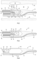
- an intravascular probe 100 includes an imaging catheter 112 with a guidewire lumen 110 defined in a monorail length section 113 at the distal end of the catheter.
- the guidewire lumen extends distally from an exit opening 111 defined in the catheter peripheral wall.
- the catheter comprises a longitudinally extending inner member in the form of a hollow torque cable or tube 136 and an outer sheath layer 114 composed of a material that is efficiently transmissive (i.e., transparent or translucent) to near infrared light.
- a material that is efficiently transmissive (i.e., transparent or translucent) to near infrared light may be, for example, petrothene or any suitable polymer that efficiently transmits infrared light.
- a transmission medium 134 such as saline or other fluid, surrounding an ultrasound transducer 120 for providing enhanced improved acoustic transmission for IVUS operation.
- the transmission medium 134 is also transparent to the infrared light emitted from an optical bench 118 for NIRS operation.
- the intravascular probe can be inserted into a lumen 106 of an artery using a guidewire 108 that is threaded through the catheter guidewire lumen 110 in monorail section 113.
- a delivery optical fiber 122 and a collection optical fiber 123 extend between proximal and distal ends of the catheter 112. The distal ends of both the collection and delivery fibers are secured to optical bench 118.
- a housing 116 may be located at the distal end or imaging tip of the torque cable 136 and houses and/or provides a mounting support for both the optical bench 118 with its NIRS components and one or more ultrasound transducers 120 serving as the IVUS components.
- the housing 116, including the optical bench 118 and the ultrasound transducer 120, may also be referred to herein as an imaging tip.
- a near infrared light source such as a laser (not shown) couples light into a proximal end of the delivery optical fiber 122 which guides the light distally to the reflective surface of a delivery mirror 124 located on optical bench 118.
- Mirror 124 is positioned to redirect the delivered light 125 toward the arterial wall 104.
- a collection mirror 126 also disposed on the optical bench 118, redirects light 127 scattered from various depths of the arterial wall 104 into the distal end of collection fiber 123 which transmits the collected light proximally in the catheter to an optical detector (not shown) for processing and analysis.
- Other light redirectors can be used in place of mirrors (e.g., prisms, bends in the optical fiber tips, etc.).
- the optical detector that receives the collected light from collection fiber 123 produces an electrical signal that contains a spectral signature indicating the composition of the arterial wall 104 and, in particular, whether the composition is consistent with the presence of lipids found in a vulnerable plaque 102.
- the spectral signature in the electrical signal can be analyzed using a spectrum analyzer (not shown) implemented in hardware, software, or a combination thereof.
- the thin annular wall of sheath 114 optimizes transmission of near infrared light therethrough without significant attenuation and distortion.
- the thin sheath wall at the imaging window section is particularly subject to kinking or bending when the catheter is pushed through an artery or similar lumen.
- the terminal length section is reinforced or strengthened. In the embodiment illustrated in FIG.
- this strengthening may be achieved by a sheath reinforcement in the form of a sleeve 140 disposed to annularly abut and surround the sheath terminal length section to be protected.
- the sleeve extends axially from, or slightly proximally of, the proximal end of the NIRS and IVUS imaging components (i.e., housing 116) to approximately the proximal end of monorail section 113.
- the sleeve 140 surrounds and structurally protects the terminal length section of the catheter most susceptible to kinking when the catheter is pushed distally in an artery.
- Sleeve 140 may be made of a material different from that of the material of catheter sheath 114, or it may be molded from the same material as an annularly thicker integral section of the catheter.
- sleeve 140 or other sheath reinforcement is constituted such that its presence does not significantly adversely affect transmission (i.e., by distortion and/or attenuation) of near infrared energy through the catheter sheath wall at the imaging window, NIRS and IVUS components can remain in the position shown and function as required. Under any circumstances, the sleeve or its equivalent sheath reinforcement should not adversely affect transmission of ultrasonic energy to and from ultrasound transducers 120 through the catheter sheath. However, cost or other considerations may force the use of sheath reinforcements that attenuate and/or distort near infrared transmission therethrough and thereby preclude effective NIRS operation at the strengthened location.
- the imaging components may be selectively pulled a short distance proximally so as to transversely align with a non-reinforced section of the catheter where the annular sheath wall is maximally transmissive to near infrared light.
- FIG. 4 Such a configuration is illustrated in FIG. 4 where the NIRS and IVUS components are shown in a retracted location, having been pulled back by torque cable 136 ( FIG. 3 ) from the terminal length section of the sheath, so as not to be surrounded by sleeve 140.
- the pullback operation is described in greater detail below.
- the material chosen for strengthening the sheath terminal length section may be chosen to permit near infrared reflection measurements to be made for system normalization or calibration purposes. More specifically, if the sleeve 140 is made more highly reflective of near infrared light, with the imaging tip at the distal end of the torque cable positioned in longitudinal alignment with the sleeve, NIRS imaging may be activated. The delivered light, rather than being transmitted out of the catheter to the arterial tissue, will be substantially reflected back from the sleeve to the collection mirror and transmitted back to the processing system as a reference signal. The resulting data can then be used for system normalization. If the sleeve is made of a plastic material, that material may be doped with material (e.g., barium sulfate, carbon black, etc.) that provides the desired near infrared reflectivity characteristics.
- material e.g., barium sulfate, carbon black, etc.
- Table I shows measurements of stiffness for ten specimens of catheters at an imaging window location that has not been strengthened according to the present invention. It is noted that mean bending or flexure modulus for these measurements is 60.732 MPa. Table II shows measurements of stiffness for ten specimens of catheters at an imaging window location that has been strengthened according to the present invention. The mean bending or flexure modulus for these measurements is 166.91 MPa, or 2.7 times that for the non-strengthened catheters.
- FIGS. 5, 5A and 5B A less schematically represented embodiment of a catheter 212 embodying the principles of the invention is illustrated in FIGS. 5, 5A and 5B .
- the catheter comprises an inner torque cable or tube 236 and an outer infrared transmissive sheath layer 214 composed of a material such as petrothene or any suitable polymer that transmits near infrared light.
- a guidewire lumen 210 is defined longitudinally through a guidewire or monorail length section 213 extending distally from the terminus of sheath 214 to define the distal end of the catheter.
- Guidewire lumen 210 extends distally from a guidewire exit opening 211 defined through the catheter peripheral wall.
- a guidewire 208 may be threaded through the catheter guidewire lumen 210 in monorail section 213 when the catheter is inserted into a lumen of an artery.
- Delivery and collection optical fibers extend within torque cable 236 between proximal and distal ends of the catheter.
- a housing 216 may be located at the distal end or tip of the torque cable 236 and houses and/or serves as a mounting support for NIRS components on an optical bench (not shown) and IVUS components in the form of one or more ultrasound transducers (not shown). Operation of the catheter in the IVUS and NIRS modes is as described in connection with FIGS. 2, 3 and 4 .
- Strengthening of catheter 212 is achieved by means of a sleeve 240 disposed to annularly abut and surround the terminal length section of the catheter to be protected.
- the sleeve extends axially and distally from a location slightly rearward or proximal of the proximal end of the NIRS and IVUS imaging components (i.e., in housing 216) to slightly beyond the proximal end of monorail section 213.
- the sleeve 240 surrounds and structurally protects the terminal length section of the sheath, which is most susceptible to kinking when the catheter is pushed distally in an artery.
- Sleeve 240 is molded from the same material as the catheter sheath 214, thereby providing the sheath as an annularly thicker integral section of the catheter.
- the sleeve 240 may be made of a strengthening material different from that of the material of the sheath, such as a plastic, metal, etc., as described above.
- the monorail section 213 has an elongate portion with a longitudinal axis laterally offset from a longitudinal axis of the outer sheath 214, and a small angled portion extending proximally from the elongate portion to the outer sheath.
- Guidewire exit 211 is formed through the elongate portion of the monorail section 213 distally of the small angled portion.
- the sleeve 240 extends distally from a location slightly rearward or proximal of housing 216 in its fully extended state, across the small angled portion of the monorail section 213 to a location along the elongate portion of the monorail section distally of the guidewire exit 211.
- sleeve 240 may reinforce and strengthen the monorail section 213 in the vicinity of guidewire exit 211 while also resisting bending or kinking of the outer sheath 214 proximally of the monorail section.
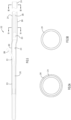
- proximal and distal ends of the sleeve 240 are tapered to avoid edges that can make it more difficult to push the catheter through the vessel and/or damage the vessel wall, and a medial portion of the sleeve is bent at an angle corresponding to the angle of the monorail's angled section.
- the reinforced portion of the monorail section 213 in the vicinity of the guidewire exit 211 has a first wall thickness
- the reinforced terminal length section of the outer sheath 214 has a second wall thickness smaller than the first wall thickness
- the remainder of the outer sheath 214 has a third wall thickness smaller than the second wall thickness.
- Exemplary dimensions for the catheter shown in FIGS. 5, 5A and 5B are as follows, it being understood that these dimensions are provided solely as perspective for understanding the invention and are not per se limiting on the scope of the invention: i.
- Sleeve 240 axial length 3.76 ⁇ 0.25 mm ii.
- Sleeve 240 outside diameter 1.118 ⁇ 0.051 mm iii.
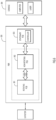
- a pullback and rotation control unit (PBR) 300 is shown as including a stationary printed circuit board (PCB) controller 303 for controlling a non-rotating PCB section 302 that is linearly movable and a rotating PCB section 301 that rotates and moves linearly.
- PCB printed circuit board
- Non-rotating PCB section 302 and rotating PCB section 301 are linearly translatable and signals may be transmitted therebetween via slip rings or the like.
- Control unit 300 serves to permit controlled rotation and longitudinal translation of the catheter torque cable 136 or 236 in FIGS. 3 and 5 , respectively, from an operator console 304 at which a system processor and a near infrared laser are located.
- Longitudinal translation is effected in a conventional manner, for example by means of a lead screw and rotary motor that power the lead screw via a pulley and belt arrangement.
- Rotating PCB 301 and the rotary motor may be mounted on a shuttle (indicated by broken lines in FIG. 6 ) that is movable linearly within PBR 300.
- Non-rotating PCB section 302 may also be mounted on the shuttle to longitudinally translate with the rotating PCB 301.
- a motor for effecting linear translation may be mounted on the housing for PBR 300.
- Motor control including pullback control, may originate from the stationary PCB controller 303 as shown, or from a controller located on the rotating PCB 301 or the non-rotating PCB 302.
- the catheter is shown in a ready position in FIGS. 3 and 5 .
- the imaging tip 116 or 216 is located in the terminal length section of the outer sheath 114 or 214.
- the imaging tip is in its fully distal position in the ready position to provide a reliable reference point for subsequent operations.
- the PBR 300 may be configured to inhibit NIRS and IVUS data collection from the imaging tip and linearly retract the imaging tip to a start position proximally spaced relative to the reinforcement means 140 or 240 (i.e., a start position), after which NIRS and/or IVUS data collection may be enabled and the imaging tip may be pulled back and rotated to acquire IVUS and NIRS data along a length of the vessel.
- Data acquisition between the ready and start positions is preferably inhibited because the sheath reinforcement may be nontransmissive of NIR light and, even if it is transmissive of IVUS energy, the sheath reinforcement may be non-uniform (e.g., uneven, tapered, and/or angled) along its length, which might cause IVUS imaging anomalies that could be mistaken for abnormalities in the vessel.
- the sheath reinforcement may be nontransmissive of NIR light and, even if it is transmissive of IVUS energy, the sheath reinforcement may be non-uniform (e.g., uneven, tapered, and/or angled) along its length, which might cause IVUS imaging anomalies that could be mistaken for abnormalities in the vessel.
- the transducer on the imaging tip may be used in the ready position to acquire and display live IVUS (LIVUS) data (e.g., by requesting LIVUS mode on the PBR unit).
- the imaging tip (and, thus, the transducer) may be retracted from the ready position to a start position proximally spaced relative to the reinforcement means before acquiring and displaying LIVUS data (e.g., by requesting pullback on the PBR).
- the catheter including the sheath and the imaging tip
- the imaging tip may be manually rotated and/or translated as a unit from outside the body to aim the ultrasound transducer within the vessel.
- controls on the PBR may be used to effect linear translation of the imaging tip (and, thus, the transducer) relative to the outer sheath.
- the PBR is configured to rotate the imaging tip as it is retracted or otherwise linearly translated relative to the outer sheath. Rotating the imaging tip during linear translation has been found to improve operation of the catheter in tortuous vessels.
- a user may request automatic pullback and rotation of the imaging tip (and, thus, the transducer) while the system is in LIVUS mode.
- the PBR may be configured to inhibit data collection and to retract the imaging tip (and, thus, the transducer) relative to the outer sheath, to a position proximally spaced relative to the reinforcement means (e.g., the start position), before initiating the pullback and rotation operation.
- the pullback and rotation operation may proceed without an initial retraction of the imaging tip.
- FIG. 7 Examples of the various states, modes or conditions of system operation 400 described above are illustrated in the flow chart shown in FIG. 7 to which reference is now made.
- the system is shown powered off at 401.
- At power on the system goes through an initialization state or mode 403 and then goes into a home rotary state or mode 405 (e.g., wherein the rotary motor spins the rotary axis of the rotating PCB until it finds an index mark in an encoder). It then places the system in a home linear state or mode 407 (e.g., by moving the lead screw until it finds the boundary of a linear sensor at the desired home position). If the sensor is not found, the user at the console may actuate keys at the console keypad or on the PBR to place the system in the home linear state.
- a home rotary state or mode 405 e.g., wherein the rotary motor spins the rotary axis of the rotating PCB until it finds an index mark in an encoder.
- a home linear state or mode 407
- both the rotational and linear axes are at home and the system enters a catheter disconnected state or mode 408 from which it can go to an idle state or mode 409 if a catheter is already connected to the PBR or it can remain in the catheter disconnected mode awaiting connection of a catheter.
- a catheter is connected to the PBR in the catheter disconnected mode 408, the system enters a catheter jog state or mode 410 in which the PBR is configured to automatically advance the carriage distally a small distance (e.g., 1 mm) to ensure that the catheter is seated on the nose piece of the PBR.
- the catheter and PBR may be configured to connect only when the imaging tip is at or very near the ready position (e.g., by configuring hub components of the catheter to align with corresponding portions of the nose piece of the PBR only when the imaging tip is at or very near the ready position).
- translation buttons on the PBR may be operable in the catheter disconnected mode 408 to linearly translate the imaging tip to the ready position. If a catheter is then connected, the system moves to the above-described catheter jog state 410, to ensure proper seating of the catheter, and enters the idle mode 409.
- the imaging tip is preferably at or near its ready (e.g., fully distal) position when the system enters the idle mode 409.
- LIVUS is requested (e.g., by actuating a LIVUS key on the PBR or console) while the system is in the idle mode 409
- the system is placed in the LIVUS requested state or mode 411 and then enters the LIVUS mode 413 in which data is being taken at the imaging tip using the ultrasound transducer. While data being acquired in LIVUS mode 413 may be displayed, the system may or may not be configured to record or save the data while in LIVUS mode.
- Other possible scenarios include:
- the initialize state 403, home rotary state 405, and home linear state 407 are examples of one time states (i.e., they occur once per reset).
- the Idle state 409, LIVUS requested state 411, LIVUS mode 413, PB requested states 415 and 423, and stop acquisition state 417 are examples of linear motion disabled states (i.e., states in which motion of the imaging tip relative to the sheath is disabled) that can occur more than once during a procedure.
- the PB moving state 417, and the LIVUS translation state 425 are examples of linear motion enabled states (i.e., states in which motion of the imaging tip relative to the sheath is enabled).
- the PBR 300 may be configured to retract the imaging tip from the ready state at a speed that is different than the speed at which it pulls back the imaging tip from the start state.
- the PBR may be configured to reposition or retract the imaging tip from the ready state to the start state at 2mm/sec or 10 mm/sec, and to pull back the imaging tip back from the start state at 0.5 mm/sec, 1 mm/sec, or 2 mm/sec while acquiring data.
- the imaging tip while in LIVUS mode, the imaging tip may be translated by the user at 2mm/sec or 10 mm/sec.
- pressure or force sensors may be mounted on the nose piece of the PBR and the system may be configured to monitor an axial force exerted on the nose piece by the inner member (e.g., the torque cable) and to enter a Force Error state or mode 429 when the imaging tip is moving distally in the sheath and the axial force on the nose piece exceeds a predetermined threshold (e.g., suggesting that the rotating imaging tip is encountering a kink in the outer sheath or an extremely tortuous anatomical feature or user error). Since excessive force can indicate a dangerous condition (e.g., a risk of penetration through the outer sheath), in the Force Error mode 429, the system may perform one or more remedial actions.
- the inner member e.g., the torque cable
- the system may automatically stop rotation and/or further linear translation of the imaging tip.
- the system may automatically retract the imaging tip proximally a predetermined distance (e.g., 10 mm).
- the system may continue to rotate the imaging tip during retraction following a force error event.
- the system may be configured to enter an In Fault state or mode 431 in which the system automatically stops rotation and linear translation of the imaging tip.
- FIG. 7 represent a particular embodiment of a system in which an imaging tip in an imaging catheter may be selectively pulled back or retracted from a position at a specified length section of the catheter.
- the pullback may be necessitated because of degradation of transmissivity of light (e.g., near infrared light) at the specified length section due to structural enhancement thereof or for other reasons (such as non-uniformity of ultrasound transmissiveness).
- transmissivity of light e.g., near infrared light
- the PBR may be configured to inhibit data collection and linearly retract the imaging tip to a position proximally spaced relative to the reinforcement means, after which data collection may be enabled and the imaging tip may be pulled back and rotated to collect NIR and/or IVUS data.
- data may be collected through the reinforcement means and subjected to data processing specific to the reinforced section which differs from the normal data processing used to process data collected through unreinforced sections of the catheter.
Landscapes
- Health & Medical Sciences (AREA)
- Life Sciences & Earth Sciences (AREA)
- Surgery (AREA)
- Physics & Mathematics (AREA)
- General Health & Medical Sciences (AREA)
- Biomedical Technology (AREA)
- Heart & Thoracic Surgery (AREA)
- Medical Informatics (AREA)
- Molecular Biology (AREA)
- Pathology (AREA)
- Animal Behavior & Ethology (AREA)
- Biophysics (AREA)
- Public Health (AREA)
- Veterinary Medicine (AREA)
- Engineering & Computer Science (AREA)
- Nuclear Medicine, Radiotherapy & Molecular Imaging (AREA)
- Radiology & Medical Imaging (AREA)
- Optics & Photonics (AREA)
- Vascular Medicine (AREA)
- Spectroscopy & Molecular Physics (AREA)
- Physiology (AREA)
- Cardiology (AREA)
- Ultra Sonic Daignosis Equipment (AREA)
- Endoscopes (AREA)
- Media Introduction/Drainage Providing Device (AREA)
Claims (17)
- Un cathéter d'imagerie (112) comprenant :une gaine externe allongée (114) réalisée en un matériau qui laisse passer la lumière dans le proche infrarouge, la gaine externe (114) comprenant une section terminale à une extrémité distale de la gaine externe (114), et une section principale s'étendant d'une extrémité proximale de la gaine externe (114) jusqu'à la section terminale ;une section pour fil-guide s'étendant distalement à partir de l'extrémité distale de la gaine externe (114) et comprenant une lumière (210) configurée pour recevoir un fil-guide ;un câble de torsion (236) disposé à rotation dans la gaine externe (114) ;un embout d'imagerie (116) situé à une extrémité distale du câble de torsion (236), l'embout d'imagerie (116) comprenant des composants optiques configurés pour émettre et recevoir de la lumière dans le proche infrarouge via la gaine externe (114) ; etun renfort de gaine (140) disposé seulement le long de la section terminale de la gaine externe (114) et configuré pour résister à une courbure transversale de la section terminale de la gaine externe (114),caractérisé en ce quela section terminale de la gaine externe (114) est renforcée, et le câble de torsion (236) est configuré pour positionner l'embout d'imagerie (116) dans la section terminale renforcée de la gaine externe (114).
- Le cathéter d'imagerie (112) de la revendication 1, dans lequel le renfort de gaine (140) comprend un manchon (140) en un matériau, entourant et venant en butée annulaire avec la section terminale de la gaine externe (114) .
- Le cathéter d'imagerie (112) de la revendication 2, dans lequel le manchon (140) est du même matériau que la gaine externe (114).
- Le cathéter d'imagerie (112) de la revendication 2, dans lequel le manchon (140) est en un matériau différent de celui de la gaine externe (114).
- Le cathéter d'imagerie (112) de la revendication 1, dans lequel le renfort de gaine (140) est configuré pour faire en sorte que la section terminale de la gaine externe (114) présente un module de flexion qui soit plus du double de celui de la section principale de la gaine externe (114).
- Le cathéter d'imagerie (112) de la revendication 1, dans lequel le renfort de gaine (140) est configuré pour faire en sorte que la section terminale de la gaine externe (114) présente un module de flexion supérieur à deux fois et demi celui de la section principale de la gaine externe (114).
- Le cathéter d'imagerie (112) de la revendication 1, dans lequel le module de flexion de la section terminale renforcée de la gaine externe (114) est supérieur à 160 MPa.
- Le cathéter d'imagerie (112) de la revendication 1, dans lequel une épaisseur combinée de la section terminale de la gaine externe (114) et du renfort de gaine (140) est supérieure au double de celle de la section principale de la gaine externe (114).
- Le cathéter d'imagerie (112) de la revendication 1, dans lequel le renfort de gaine (140) présente une longueur qui est supérieure à celle de l'embout d'imagerie (116).
- Le cathéter d'imagerie (112) de la revendication 1, dans lequel le renfort de gaine (140) s'étend distalement au-delà de la section terminale de la gaine externe (114) vers la section pour fil-guide.
- Le cathéter d'imagerie (112) de la revendication 1, dans lequel le renfort de gaine (140) est réalisé en un matériau qui réfléchit la lumière dans le proche infrarouge.
- Le cathéter d'imagerie (112) de la revendication 1, dans lequel le renfort de gaine (140) est dopé par un matériau de dopage qui procure une réflectivité dans le proche infrarouge.
- Le cathéter d'imagerie (112) de la revendication 12, dans lequel le matériau dopant est choisi dans le groupe comprenant le sulfate de baryum et le noir de carbone.
- Le cathéter d'imagerie (112) de la revendication 1, dans lequel l'embout d'imagerie (116) comprend en outre un transducteur à ultrasons, et dans lequel la section terminale et le renfort de gaine (140) transmettent tous les deux l'énergie des ultrasons.
- Le cathéter d'imagerie (112) de la revendication 1, dans lequel le renfort de gaine (140) présente des caractéristiques optiques qui limitent la transmission de la lumière dans le proche infrarouge qui le traverse, et comprenant en outre un système d'entraînement de recul comprenant un étage de translation linéaire couplé au câble (236) et configuré pour assurer le retrait sélectif du câble (236) proximalement pour replacer axialement l'embout d'imagerie (116) immédiatement proximal à la section terminale de la gaine externe (114) et du renfort de gaine (140).
- Un procédé de fabrication d'un cathéter d'imagerie intraluminal selon la revendication 1, ledit procédé comprenant la mise en place d'un manchon de matériau en relation d'entourage et de venue en butée annulaire seulement avec la section terminale de la gaine, et le positionnement de l'embout d'imagerie sur l'extrémité distale du câble de torsion dans la section terminale de la gaine, pour empêcher que la gaine transmettant la lumière dans le proche infrarouge ne se coude lorsque le cathéter est poussé distalement dans un vaisseau sanguin ou analogue à l'aide d'un fil-guide enfilé dans la section de lumière pour fil-guide à une extrémité distale du cathéter.
- Le procédé de la revendication 16, dans lequel l'étape de mise en place comprend la formation du manchon par moulage de celui-ci avec la gaine externe.
Applications Claiming Priority (2)
| Application Number | Priority Date | Filing Date | Title |
|---|---|---|---|
| US201762558913P | 2017-09-15 | 2017-09-15 | |
| PCT/US2018/050997 WO2019055736A1 (fr) | 2017-09-15 | 2018-09-14 | Cathéter d'imagerie |
Publications (3)
| Publication Number | Publication Date |
|---|---|
| EP3618723A1 EP3618723A1 (fr) | 2020-03-11 |
| EP3618723A4 EP3618723A4 (fr) | 2021-01-27 |
| EP3618723B1 true EP3618723B1 (fr) | 2024-07-24 |
Family
ID=65719610
Family Applications (2)
| Application Number | Title | Priority Date | Filing Date |
|---|---|---|---|
| EP18855537.9A Active EP3618723B1 (fr) | 2017-09-15 | 2018-09-14 | Cathéter d'imagerie |
| EP18857076.6A Active EP3627993B1 (fr) | 2017-09-15 | 2018-09-14 | Cathéter d'imagerie doté d'une section renforcée |
Family Applications After (1)
| Application Number | Title | Priority Date | Filing Date |
|---|---|---|---|
| EP18857076.6A Active EP3627993B1 (fr) | 2017-09-15 | 2018-09-14 | Cathéter d'imagerie doté d'une section renforcée |
Country Status (4)
| Country | Link |
|---|---|
| US (4) | US11284860B2 (fr) |
| EP (2) | EP3618723B1 (fr) |
| JP (2) | JP7026202B2 (fr) |
| WO (2) | WO2019055739A1 (fr) |
Families Citing this family (7)
| Publication number | Priority date | Publication date | Assignee | Title |
|---|---|---|---|---|
| EP3618723B1 (fr) * | 2017-09-15 | 2024-07-24 | INFRAREDEX, Inc. | Cathéter d'imagerie |
| US11972561B2 (en) * | 2020-08-06 | 2024-04-30 | Canon U.S.A., Inc. | Auto-pullback triggering method for intracoronary imaging apparatuses or systems using blood clearing |
| US12458778B2 (en) | 2020-08-06 | 2025-11-04 | Canon U.S.A., Inc. | Optimized catheter sheath for Rx catheter |
| US12112488B2 (en) | 2020-08-06 | 2024-10-08 | Canon U.S.A., Inc. | Methods and systems for image synchronization |
| JP7487319B2 (ja) * | 2020-09-08 | 2024-05-20 | 朝日インテック株式会社 | カテーテル、及び、再開通カテーテルシステム |
| JP7624650B2 (ja) * | 2020-11-06 | 2025-01-31 | 朝日インテック株式会社 | 光照射デバイス、及び、光照射システム |
| JP7674170B2 (ja) * | 2021-06-30 | 2025-05-09 | カーディナルヘルス株式会社 | 体内留置型医療デバイス、及びこれを用いた内視鏡システム |
Family Cites Families (49)
| Publication number | Priority date | Publication date | Assignee | Title |
|---|---|---|---|---|
| US5372138A (en) | 1988-03-21 | 1994-12-13 | Boston Scientific Corporation | Acousting imaging catheters and the like |
| US5024234A (en) | 1989-10-17 | 1991-06-18 | Cardiovascular Imaging Systems, Inc. | Ultrasonic imaging catheter with guidewire channel |
| EP0563179B1 (fr) | 1990-12-17 | 1997-08-27 | Cardiovascular Imaging Systems, Inc. | Catheter vasculaire dont l'extremite distale a un profile mince |
| US5445155A (en) | 1991-03-13 | 1995-08-29 | Scimed Life Systems Incorporated | Intravascular imaging apparatus and methods for use and manufacture |
| US5201316A (en) | 1991-03-18 | 1993-04-13 | Cardiovascular Imaging Systems, Inc. | Guide wire receptacle for catheters having rigid housings |
| DK0626823T3 (da) | 1992-02-21 | 2000-09-11 | Boston Scient Ltd | Ledetråd til ultralydbilleddannelse |
| US5300048A (en) * | 1993-05-12 | 1994-04-05 | Sabin Corporation | Flexible, highly radiopaque plastic material catheter |
| US5458585A (en) | 1993-07-28 | 1995-10-17 | Cardiovascular Imaging Systems, Inc. | Tracking tip for a work element in a catheter system |
| US5443457A (en) | 1994-02-24 | 1995-08-22 | Cardiovascular Imaging Systems, Incorporated | Tracking tip for a short lumen rapid exchange catheter |
| JPH08206114A (ja) | 1995-02-02 | 1996-08-13 | Terumo Corp | 超音波カテーテル |
| US5738100A (en) | 1995-06-30 | 1998-04-14 | Terumo Kabushiki Kaisha | Ultrasonic imaging catheter |
| JP3754500B2 (ja) | 1995-06-30 | 2006-03-15 | テルモ株式会社 | 超音波カテーテル |
| US6050949A (en) | 1997-09-22 | 2000-04-18 | Scimed Life Systems, Inc. | Catheher system having connectable distal and proximal portions |
| US6078831A (en) | 1997-09-29 | 2000-06-20 | Scimed Life Systems, Inc. | Intravascular imaging guidewire |
| WO1999016347A1 (fr) | 1997-09-29 | 1999-04-08 | Scimed Life Systems, Inc. | Fil-guide d'imagerie intravasculaire |
| US6419644B1 (en) | 1998-09-08 | 2002-07-16 | Scimed Life Systems, Inc. | System and method for intraluminal imaging |
| US6162179A (en) | 1998-12-08 | 2000-12-19 | Scimed Life Systems, Inc. | Loop imaging catheter |
| US6508804B2 (en) | 1999-07-28 | 2003-01-21 | Scimed Life Systems, Inc. | Catheter having continuous lattice and coil reinforcement |
| US6615062B2 (en) | 2001-05-31 | 2003-09-02 | Infraredx, Inc. | Referencing optical catheters |
| JP4672188B2 (ja) | 2001-06-08 | 2011-04-20 | テルモ株式会社 | 超音波カテーテル |
| AU2003223749A1 (en) | 2002-04-25 | 2003-11-10 | The Board Of Trustees Of The Leland Stanford Junior University | Expandable guide sheath and apparatus and methods using such sheaths |
| US7672713B2 (en) | 2002-06-19 | 2010-03-02 | Infraredx, Inc. | Multi-channel catheter tip |
| US7335180B2 (en) | 2003-11-24 | 2008-02-26 | Flowcardia, Inc. | Steerable ultrasound catheter |
| US6966891B2 (en) | 2002-08-27 | 2005-11-22 | Terumo Kabushiki Kaisha | Catheter |
| JP4065167B2 (ja) | 2002-09-05 | 2008-03-19 | テルモ株式会社 | カテーテル |
| US20040193034A1 (en) | 2003-03-28 | 2004-09-30 | Lawrence Wasicek | Combined long rail/short rail IVUS catheter |
| US6949072B2 (en) * | 2003-09-22 | 2005-09-27 | Infraredx, Inc. | Devices for vulnerable plaque detection |
| JP2004275784A (ja) | 2004-06-24 | 2004-10-07 | Terumo Corp | 超音波カテーテル |
| DE102005059261B4 (de) | 2005-12-12 | 2013-09-05 | Siemens Aktiengesellschaft | Kathetervorrichtung zur Behandlung eines teilweisen und/oder vollständigen Gefässverschlusses und Röntgeneinrichtung |
| JP2009544356A (ja) | 2006-07-21 | 2009-12-17 | プレサイエント メディカル, インコーポレイテッド | 適合可能な組織接触カテーテル |
| US8864675B2 (en) | 2007-06-28 | 2014-10-21 | W. L. Gore & Associates, Inc. | Catheter |
| US8285362B2 (en) | 2007-06-28 | 2012-10-09 | W. L. Gore & Associates, Inc. | Catheter with deflectable imaging device |
| US9622706B2 (en) | 2007-07-12 | 2017-04-18 | Volcano Corporation | Catheter for in vivo imaging |
| US8277381B2 (en) | 2007-12-21 | 2012-10-02 | Boston Scientific Scimed, Inc. | Low profile intravascular ultrasound catheter |
| US9713448B2 (en) | 2008-04-03 | 2017-07-25 | Infraredx, Inc. | System and method for intravascular structural analysis compensation of chemical analysis modality |
| US20090270815A1 (en) * | 2008-04-29 | 2009-10-29 | Infraredx, Inc. | Catheter Priming System |
| US8052605B2 (en) * | 2008-05-07 | 2011-11-08 | Infraredx | Multimodal catheter system and method for intravascular analysis |
| WO2010103718A1 (fr) | 2009-03-12 | 2010-09-16 | テルモ株式会社 | Dispositif d'imagerie de diagnostic et procédé de commande de celui-ci |
| US8876722B2 (en) | 2009-07-23 | 2014-11-04 | Acist Medical Systems, Inc. | Endoventricular injection catheter system with integrated echocardiographic capabilities |
| WO2011027821A1 (fr) | 2009-09-04 | 2011-03-10 | テルモ株式会社 | Cathéter |
| WO2011033938A1 (fr) | 2009-09-15 | 2011-03-24 | テルモ株式会社 | Cathéter |
| JP2011067262A (ja) | 2009-09-24 | 2011-04-07 | Terumo Corp | 体腔内診断システム |
| JP5436266B2 (ja) | 2010-02-26 | 2014-03-05 | 朝日インテック株式会社 | 医療用コイル構造体と、その製造方法、並びに医療用コイル構造体を形成して成る医療用内視鏡と、医療用処置具と、超音波診断医療用カテーテルと、光干渉診断医療用カテーテル |
| CN102802492B (zh) | 2010-03-16 | 2015-02-11 | 泰尔茂株式会社 | 导丝及导管组装体 |
| US10905851B2 (en) | 2012-03-23 | 2021-02-02 | Acist Medical Systems, Inc. | Catheter sheath and methods thereof |
| JP2015536223A (ja) | 2012-12-06 | 2015-12-21 | ヴォルカノ コーポレイションVolcano Corporation | 柔軟な端部を有する強化カテーテル移行 |
| EP3011315A4 (fr) | 2013-06-19 | 2017-02-22 | The General Hospital Corporation | Appareil, dispositifs et procédés pour obtenir une visualisation omnidirectionnelle par un cathéter |
| JP6923545B2 (ja) | 2016-02-26 | 2021-08-18 | サニーブルック リサーチ インスティチュート | 回転可能なコアを有する撮像プローブ |
| EP3618723B1 (fr) * | 2017-09-15 | 2024-07-24 | INFRAREDEX, Inc. | Cathéter d'imagerie |
-
2018
- 2018-09-14 EP EP18855537.9A patent/EP3618723B1/fr active Active
- 2018-09-14 EP EP18857076.6A patent/EP3627993B1/fr active Active
- 2018-09-14 US US16/131,177 patent/US11284860B2/en active Active
- 2018-09-14 WO PCT/US2018/051000 patent/WO2019055739A1/fr not_active Ceased
- 2018-09-14 WO PCT/US2018/050997 patent/WO2019055736A1/fr not_active Ceased
- 2018-09-14 JP JP2020503904A patent/JP7026202B2/ja active Active
- 2018-09-14 US US16/131,183 patent/US11331074B2/en active Active
- 2018-09-14 JP JP2020504008A patent/JP7084468B2/ja active Active
-
2022
- 2022-03-29 US US17/707,285 patent/US12465328B2/en active Active
- 2022-04-20 US US17/724,891 patent/US12076188B2/en active Active
Also Published As
| Publication number | Publication date |
|---|---|
| JP2020529232A (ja) | 2020-10-08 |
| US20190082965A1 (en) | 2019-03-21 |
| US20220218307A1 (en) | 2022-07-14 |
| WO2019055739A1 (fr) | 2019-03-21 |
| US20220249057A1 (en) | 2022-08-11 |
| JP7084468B2 (ja) | 2022-06-14 |
| US11284860B2 (en) | 2022-03-29 |
| EP3627993B1 (fr) | 2024-07-31 |
| WO2019055736A1 (fr) | 2019-03-21 |
| JP7026202B2 (ja) | 2022-02-25 |
| EP3627993A4 (fr) | 2021-06-16 |
| US12076188B2 (en) | 2024-09-03 |
| US11331074B2 (en) | 2022-05-17 |
| US12465328B2 (en) | 2025-11-11 |
| EP3627993A1 (fr) | 2020-04-01 |
| EP3618723A4 (fr) | 2021-01-27 |
| EP3618723A1 (fr) | 2020-03-11 |
| US20190083062A1 (en) | 2019-03-21 |
| JP2020528789A (ja) | 2020-10-01 |
Similar Documents
| Publication | Publication Date | Title |
|---|---|---|
| US12076188B2 (en) | Method of using an imaging catheter with a reinforced section | |
| US7785286B2 (en) | Method and system for imaging, diagnosing, and/or treating an area of interest in a patient's body | |
| JP5188242B2 (ja) | 生体内挿入用プローブ | |
| US9119936B2 (en) | Catheter with spiral slit terminating in slit termination portion oriented to suppress crack occurrence | |
| US7155272B2 (en) | Catheter | |
| EP2081486B1 (fr) | Dispositif d'imagerie opto-acoustique | |
| US12403285B2 (en) | Intravascular imaging catheter system with force error detection and automatic remediation via pullback and rotation | |
| EP3185781B1 (fr) | Dispositifs intravasculaires possédant des orifices d'échange rapide renforcés, et systèmes associés | |
| JP5864182B2 (ja) | モータ駆動装置及び画像診断装置 | |
| WO2021065312A1 (fr) | Jeu d'instruments médicaux et élément tubulaire | |
| JP5171355B2 (ja) | 生体内挿入用プローブ装置 | |
| JP5171354B2 (ja) | 生体内画像診断プローブ | |
| EP3717051B1 (fr) | Système d'imagerie intravasculaire avec détection et correction d'erreur de force | |
| JP2025538686A (ja) | 血管内撮像デバイス | |
| JP6779799B2 (ja) | 医療デバイス | |
| US20120277580A1 (en) | System and method for diluting blood in a vessel |
Legal Events
| Date | Code | Title | Description |
|---|---|---|---|
| STAA | Information on the status of an ep patent application or granted ep patent |
Free format text: STATUS: THE INTERNATIONAL PUBLICATION HAS BEEN MADE |
|
| PUAI | Public reference made under article 153(3) epc to a published international application that has entered the european phase |
Free format text: ORIGINAL CODE: 0009012 |
|
| STAA | Information on the status of an ep patent application or granted ep patent |
Free format text: STATUS: REQUEST FOR EXAMINATION WAS MADE |
|
| 17P | Request for examination filed |
Effective date: 20191202 |
|
| AK | Designated contracting states |
Kind code of ref document: A1 Designated state(s): AL AT BE BG CH CY CZ DE DK EE ES FI FR GB GR HR HU IE IS IT LI LT LU LV MC MK MT NL NO PL PT RO RS SE SI SK SM TR |
|
| AX | Request for extension of the european patent |
Extension state: BA ME |
|
| DAV | Request for validation of the european patent (deleted) | ||
| DAX | Request for extension of the european patent (deleted) | ||
| A4 | Supplementary search report drawn up and despatched |
Effective date: 20210114 |
|
| RIC1 | Information provided on ipc code assigned before grant |
Ipc: G01S 15/89 20060101ALI20201223BHEP Ipc: G01N 21/35 20140101ALI20201223BHEP Ipc: A61B 5/1459 20060101ALI20201223BHEP Ipc: A61B 8/00 20060101ALI20201223BHEP Ipc: A61B 5/00 20060101ALI20201223BHEP Ipc: A61B 10/00 20060101AFI20201223BHEP Ipc: A61B 8/08 20060101ALN20201223BHEP Ipc: A61B 5/02 20060101ALI20201223BHEP Ipc: A61B 8/13 20060101ALI20201223BHEP Ipc: A61B 8/12 20060101ALI20201223BHEP |
|
| STAA | Information on the status of an ep patent application or granted ep patent |
Free format text: STATUS: EXAMINATION IS IN PROGRESS |
|
| 17Q | First examination report despatched |
Effective date: 20230620 |
|
| GRAP | Despatch of communication of intention to grant a patent |
Free format text: ORIGINAL CODE: EPIDOSNIGR1 |
|
| STAA | Information on the status of an ep patent application or granted ep patent |
Free format text: STATUS: GRANT OF PATENT IS INTENDED |
|
| RIC1 | Information provided on ipc code assigned before grant |
Ipc: A61B 8/08 20060101ALN20240425BHEP Ipc: A61B 1/04 20060101ALI20240425BHEP Ipc: A61B 1/00 20060101ALI20240425BHEP Ipc: A61B 8/00 20060101ALI20240425BHEP Ipc: G01S 15/89 20060101ALI20240425BHEP Ipc: G01N 21/35 20140101ALI20240425BHEP Ipc: A61B 8/13 20060101ALI20240425BHEP Ipc: A61B 8/12 20060101ALI20240425BHEP Ipc: A61B 5/1459 20060101ALI20240425BHEP Ipc: A61B 5/02 20060101ALI20240425BHEP Ipc: A61B 5/00 20060101ALI20240425BHEP Ipc: A61B 10/00 20060101AFI20240425BHEP |
|
| GRAS | Grant fee paid |
Free format text: ORIGINAL CODE: EPIDOSNIGR3 |
|
| INTG | Intention to grant announced |
Effective date: 20240514 |
|
| RIN1 | Information on inventor provided before grant (corrected) |
Inventor name: MADDEN, SEAN, P. Inventor name: DEROSA, KATHLEEN Inventor name: BARONE, DAVID |
|
| GRAA | (expected) grant |
Free format text: ORIGINAL CODE: 0009210 |
|
| STAA | Information on the status of an ep patent application or granted ep patent |
Free format text: STATUS: THE PATENT HAS BEEN GRANTED |
|
| AK | Designated contracting states |
Kind code of ref document: B1 Designated state(s): AL AT BE BG CH CY CZ DE DK EE ES FI FR GB GR HR HU IE IS IT LI LT LU LV MC MK MT NL NO PL PT RO RS SE SI SK SM TR |
|
| REG | Reference to a national code |
Ref country code: GB Ref legal event code: FG4D |
|
| REG | Reference to a national code |
Ref country code: CH Ref legal event code: EP |
|
| REG | Reference to a national code |
Ref country code: IE Ref legal event code: FG4D Ref country code: DE Ref legal event code: R096 Ref document number: 602018072283 Country of ref document: DE |
|
| REG | Reference to a national code |
Ref country code: LT Ref legal event code: MG9D |
|
| REG | Reference to a national code |
Ref country code: NL Ref legal event code: MP Effective date: 20240724 |
|
| PG25 | Lapsed in a contracting state [announced via postgrant information from national office to epo] |
Ref country code: PT Free format text: LAPSE BECAUSE OF FAILURE TO SUBMIT A TRANSLATION OF THE DESCRIPTION OR TO PAY THE FEE WITHIN THE PRESCRIBED TIME-LIMIT Effective date: 20241125 |
|
| REG | Reference to a national code |
Ref country code: AT Ref legal event code: MK05 Ref document number: 1705528 Country of ref document: AT Kind code of ref document: T Effective date: 20240724 |
|
| PG25 | Lapsed in a contracting state [announced via postgrant information from national office to epo] |
Ref country code: NL Free format text: LAPSE BECAUSE OF FAILURE TO SUBMIT A TRANSLATION OF THE DESCRIPTION OR TO PAY THE FEE WITHIN THE PRESCRIBED TIME-LIMIT Effective date: 20240724 |
|
| PG25 | Lapsed in a contracting state [announced via postgrant information from national office to epo] |
Ref country code: PT Free format text: LAPSE BECAUSE OF FAILURE TO SUBMIT A TRANSLATION OF THE DESCRIPTION OR TO PAY THE FEE WITHIN THE PRESCRIBED TIME-LIMIT Effective date: 20241125 Ref country code: NL Free format text: LAPSE BECAUSE OF FAILURE TO SUBMIT A TRANSLATION OF THE DESCRIPTION OR TO PAY THE FEE WITHIN THE PRESCRIBED TIME-LIMIT Effective date: 20240724 |
|
| PG25 | Lapsed in a contracting state [announced via postgrant information from national office to epo] |
Ref country code: NO Free format text: LAPSE BECAUSE OF FAILURE TO SUBMIT A TRANSLATION OF THE DESCRIPTION OR TO PAY THE FEE WITHIN THE PRESCRIBED TIME-LIMIT Effective date: 20241024 |
|
| PG25 | Lapsed in a contracting state [announced via postgrant information from national office to epo] |
Ref country code: GR Free format text: LAPSE BECAUSE OF FAILURE TO SUBMIT A TRANSLATION OF THE DESCRIPTION OR TO PAY THE FEE WITHIN THE PRESCRIBED TIME-LIMIT Effective date: 20241025 Ref country code: PL Free format text: LAPSE BECAUSE OF FAILURE TO SUBMIT A TRANSLATION OF THE DESCRIPTION OR TO PAY THE FEE WITHIN THE PRESCRIBED TIME-LIMIT Effective date: 20240724 Ref country code: FI Free format text: LAPSE BECAUSE OF FAILURE TO SUBMIT A TRANSLATION OF THE DESCRIPTION OR TO PAY THE FEE WITHIN THE PRESCRIBED TIME-LIMIT Effective date: 20240724 |
|
| PG25 | Lapsed in a contracting state [announced via postgrant information from national office to epo] |
Ref country code: BG Free format text: LAPSE BECAUSE OF FAILURE TO SUBMIT A TRANSLATION OF THE DESCRIPTION OR TO PAY THE FEE WITHIN THE PRESCRIBED TIME-LIMIT Effective date: 20240724 |
|
| PG25 | Lapsed in a contracting state [announced via postgrant information from national office to epo] |
Ref country code: LV Free format text: LAPSE BECAUSE OF FAILURE TO SUBMIT A TRANSLATION OF THE DESCRIPTION OR TO PAY THE FEE WITHIN THE PRESCRIBED TIME-LIMIT Effective date: 20240724 |
|
| PG25 | Lapsed in a contracting state [announced via postgrant information from national office to epo] |
Ref country code: IS Free format text: LAPSE BECAUSE OF FAILURE TO SUBMIT A TRANSLATION OF THE DESCRIPTION OR TO PAY THE FEE WITHIN THE PRESCRIBED TIME-LIMIT Effective date: 20241124 Ref country code: AT Free format text: LAPSE BECAUSE OF FAILURE TO SUBMIT A TRANSLATION OF THE DESCRIPTION OR TO PAY THE FEE WITHIN THE PRESCRIBED TIME-LIMIT Effective date: 20240724 |
|
| PG25 | Lapsed in a contracting state [announced via postgrant information from national office to epo] |
Ref country code: HR Free format text: LAPSE BECAUSE OF FAILURE TO SUBMIT A TRANSLATION OF THE DESCRIPTION OR TO PAY THE FEE WITHIN THE PRESCRIBED TIME-LIMIT Effective date: 20240724 |
|
| PG25 | Lapsed in a contracting state [announced via postgrant information from national office to epo] |
Ref country code: RS Free format text: LAPSE BECAUSE OF FAILURE TO SUBMIT A TRANSLATION OF THE DESCRIPTION OR TO PAY THE FEE WITHIN THE PRESCRIBED TIME-LIMIT Effective date: 20241024 Ref country code: ES Free format text: LAPSE BECAUSE OF FAILURE TO SUBMIT A TRANSLATION OF THE DESCRIPTION OR TO PAY THE FEE WITHIN THE PRESCRIBED TIME-LIMIT Effective date: 20240724 |
|
| PG25 | Lapsed in a contracting state [announced via postgrant information from national office to epo] |
Ref country code: RS Free format text: LAPSE BECAUSE OF FAILURE TO SUBMIT A TRANSLATION OF THE DESCRIPTION OR TO PAY THE FEE WITHIN THE PRESCRIBED TIME-LIMIT Effective date: 20241024 Ref country code: PL Free format text: LAPSE BECAUSE OF FAILURE TO SUBMIT A TRANSLATION OF THE DESCRIPTION OR TO PAY THE FEE WITHIN THE PRESCRIBED TIME-LIMIT Effective date: 20240724 Ref country code: NO Free format text: LAPSE BECAUSE OF FAILURE TO SUBMIT A TRANSLATION OF THE DESCRIPTION OR TO PAY THE FEE WITHIN THE PRESCRIBED TIME-LIMIT Effective date: 20241024 Ref country code: LV Free format text: LAPSE BECAUSE OF FAILURE TO SUBMIT A TRANSLATION OF THE DESCRIPTION OR TO PAY THE FEE WITHIN THE PRESCRIBED TIME-LIMIT Effective date: 20240724 Ref country code: IS Free format text: LAPSE BECAUSE OF FAILURE TO SUBMIT A TRANSLATION OF THE DESCRIPTION OR TO PAY THE FEE WITHIN THE PRESCRIBED TIME-LIMIT Effective date: 20241124 Ref country code: HR Free format text: LAPSE BECAUSE OF FAILURE TO SUBMIT A TRANSLATION OF THE DESCRIPTION OR TO PAY THE FEE WITHIN THE PRESCRIBED TIME-LIMIT Effective date: 20240724 Ref country code: GR Free format text: LAPSE BECAUSE OF FAILURE TO SUBMIT A TRANSLATION OF THE DESCRIPTION OR TO PAY THE FEE WITHIN THE PRESCRIBED TIME-LIMIT Effective date: 20241025 Ref country code: FI Free format text: LAPSE BECAUSE OF FAILURE TO SUBMIT A TRANSLATION OF THE DESCRIPTION OR TO PAY THE FEE WITHIN THE PRESCRIBED TIME-LIMIT Effective date: 20240724 Ref country code: ES Free format text: LAPSE BECAUSE OF FAILURE TO SUBMIT A TRANSLATION OF THE DESCRIPTION OR TO PAY THE FEE WITHIN THE PRESCRIBED TIME-LIMIT Effective date: 20240724 Ref country code: BG Free format text: LAPSE BECAUSE OF FAILURE TO SUBMIT A TRANSLATION OF THE DESCRIPTION OR TO PAY THE FEE WITHIN THE PRESCRIBED TIME-LIMIT Effective date: 20240724 Ref country code: AT Free format text: LAPSE BECAUSE OF FAILURE TO SUBMIT A TRANSLATION OF THE DESCRIPTION OR TO PAY THE FEE WITHIN THE PRESCRIBED TIME-LIMIT Effective date: 20240724 |
|
| PG25 | Lapsed in a contracting state [announced via postgrant information from national office to epo] |
Ref country code: SM Free format text: LAPSE BECAUSE OF FAILURE TO SUBMIT A TRANSLATION OF THE DESCRIPTION OR TO PAY THE FEE WITHIN THE PRESCRIBED TIME-LIMIT Effective date: 20240724 Ref country code: DK Free format text: LAPSE BECAUSE OF FAILURE TO SUBMIT A TRANSLATION OF THE DESCRIPTION OR TO PAY THE FEE WITHIN THE PRESCRIBED TIME-LIMIT Effective date: 20240724 Ref country code: RO Free format text: LAPSE BECAUSE OF FAILURE TO SUBMIT A TRANSLATION OF THE DESCRIPTION OR TO PAY THE FEE WITHIN THE PRESCRIBED TIME-LIMIT Effective date: 20240724 |
|
| PG25 | Lapsed in a contracting state [announced via postgrant information from national office to epo] |
Ref country code: MC Free format text: LAPSE BECAUSE OF FAILURE TO SUBMIT A TRANSLATION OF THE DESCRIPTION OR TO PAY THE FEE WITHIN THE PRESCRIBED TIME-LIMIT Effective date: 20240724 Ref country code: EE Free format text: LAPSE BECAUSE OF FAILURE TO SUBMIT A TRANSLATION OF THE DESCRIPTION OR TO PAY THE FEE WITHIN THE PRESCRIBED TIME-LIMIT Effective date: 20240724 |
|
| PG25 | Lapsed in a contracting state [announced via postgrant information from national office to epo] |
Ref country code: CZ Free format text: LAPSE BECAUSE OF FAILURE TO SUBMIT A TRANSLATION OF THE DESCRIPTION OR TO PAY THE FEE WITHIN THE PRESCRIBED TIME-LIMIT Effective date: 20240724 |
|
| REG | Reference to a national code |
Ref country code: DE Ref legal event code: R097 Ref document number: 602018072283 Country of ref document: DE |
|
| PG25 | Lapsed in a contracting state [announced via postgrant information from national office to epo] |
Ref country code: IT Free format text: LAPSE BECAUSE OF FAILURE TO SUBMIT A TRANSLATION OF THE DESCRIPTION OR TO PAY THE FEE WITHIN THE PRESCRIBED TIME-LIMIT Effective date: 20240724 Ref country code: SK Free format text: LAPSE BECAUSE OF FAILURE TO SUBMIT A TRANSLATION OF THE DESCRIPTION OR TO PAY THE FEE WITHIN THE PRESCRIBED TIME-LIMIT Effective date: 20240724 |
|
| REG | Reference to a national code |
Ref country code: CH Ref legal event code: PL |
|
| PG25 | Lapsed in a contracting state [announced via postgrant information from national office to epo] |
Ref country code: LU Free format text: LAPSE BECAUSE OF NON-PAYMENT OF DUE FEES Effective date: 20240914 |
|
| PLBE | No opposition filed within time limit |
Free format text: ORIGINAL CODE: 0009261 |
|
| STAA | Information on the status of an ep patent application or granted ep patent |
Free format text: STATUS: NO OPPOSITION FILED WITHIN TIME LIMIT |
|
| 26N | No opposition filed |
Effective date: 20250425 |
|
| REG | Reference to a national code |
Ref country code: BE Ref legal event code: MM Effective date: 20240930 |
|
| PG25 | Lapsed in a contracting state [announced via postgrant information from national office to epo] |
Ref country code: BE Free format text: LAPSE BECAUSE OF NON-PAYMENT OF DUE FEES Effective date: 20240930 |
|
| PG25 | Lapsed in a contracting state [announced via postgrant information from national office to epo] |
Ref country code: CH Free format text: LAPSE BECAUSE OF NON-PAYMENT OF DUE FEES Effective date: 20240930 |
|
| PG25 | Lapsed in a contracting state [announced via postgrant information from national office to epo] |
Ref country code: IE Free format text: LAPSE BECAUSE OF NON-PAYMENT OF DUE FEES Effective date: 20240914 |
|
| PG25 | Lapsed in a contracting state [announced via postgrant information from national office to epo] |
Ref country code: SE Free format text: LAPSE BECAUSE OF FAILURE TO SUBMIT A TRANSLATION OF THE DESCRIPTION OR TO PAY THE FEE WITHIN THE PRESCRIBED TIME-LIMIT Effective date: 20240724 |
|
| PGFP | Annual fee paid to national office [announced via postgrant information from national office to epo] |
Ref country code: DE Payment date: 20250919 Year of fee payment: 8 |
|
| PGFP | Annual fee paid to national office [announced via postgrant information from national office to epo] |
Ref country code: GB Payment date: 20250919 Year of fee payment: 8 |
|
| PGFP | Annual fee paid to national office [announced via postgrant information from national office to epo] |
Ref country code: FR Payment date: 20250922 Year of fee payment: 8 |
|
| PG25 | Lapsed in a contracting state [announced via postgrant information from national office to epo] |
Ref country code: CY Free format text: LAPSE BECAUSE OF FAILURE TO SUBMIT A TRANSLATION OF THE DESCRIPTION OR TO PAY THE FEE WITHIN THE PRESCRIBED TIME-LIMIT; INVALID AB INITIO Effective date: 20180914 |
|
| PG25 | Lapsed in a contracting state [announced via postgrant information from national office to epo] |
Ref country code: HU Free format text: LAPSE BECAUSE OF FAILURE TO SUBMIT A TRANSLATION OF THE DESCRIPTION OR TO PAY THE FEE WITHIN THE PRESCRIBED TIME-LIMIT; INVALID AB INITIO Effective date: 20180914 |