EP3621382B1 - Datenübertragungsverfahren und .vorrichtung, speichermedium und prozessor - Google Patents
Datenübertragungsverfahren und .vorrichtung, speichermedium und prozessor Download PDFInfo
- Publication number
- EP3621382B1 EP3621382B1 EP18794377.4A EP18794377A EP3621382B1 EP 3621382 B1 EP3621382 B1 EP 3621382B1 EP 18794377 A EP18794377 A EP 18794377A EP 3621382 B1 EP3621382 B1 EP 3621382B1
- Authority
- EP
- European Patent Office
- Prior art keywords
- slot
- transmission
- information
- node
- transmission period
- Prior art date
- Legal status (The legal status is an assumption and is not a legal conclusion. Google has not performed a legal analysis and makes no representation as to the accuracy of the status listed.)
- Active
Links
Images


Classifications
-
- H—ELECTRICITY
- H04—ELECTRIC COMMUNICATION TECHNIQUE
- H04L—TRANSMISSION OF DIGITAL INFORMATION, e.g. TELEGRAPHIC COMMUNICATION
- H04L1/00—Arrangements for detecting or preventing errors in the information received
- H04L1/12—Arrangements for detecting or preventing errors in the information received by using return channel
- H04L1/16—Arrangements for detecting or preventing errors in the information received by using return channel in which the return channel carries supervisory signals, e.g. repetition request signals
- H04L1/1607—Details of the supervisory signal
-
- H—ELECTRICITY
- H04—ELECTRIC COMMUNICATION TECHNIQUE
- H04L—TRANSMISSION OF DIGITAL INFORMATION, e.g. TELEGRAPHIC COMMUNICATION
- H04L27/00—Modulated-carrier systems
- H04L27/26—Systems using multi-frequency codes
- H04L27/2601—Multicarrier modulation systems
- H04L27/2647—Arrangements specific to the receiver only
- H04L27/2655—Synchronisation arrangements
-
- H—ELECTRICITY
- H04—ELECTRIC COMMUNICATION TECHNIQUE
- H04L—TRANSMISSION OF DIGITAL INFORMATION, e.g. TELEGRAPHIC COMMUNICATION
- H04L5/00—Arrangements affording multiple use of the transmission path
- H04L5/003—Arrangements for allocating sub-channels of the transmission path
- H04L5/0032—Distributed allocation, i.e. involving a plurality of allocating devices, each making partial allocation
- H04L5/0035—Resource allocation in a cooperative multipoint environment
-
- H—ELECTRICITY
- H04—ELECTRIC COMMUNICATION TECHNIQUE
- H04L—TRANSMISSION OF DIGITAL INFORMATION, e.g. TELEGRAPHIC COMMUNICATION
- H04L5/00—Arrangements affording multiple use of the transmission path
- H04L5/003—Arrangements for allocating sub-channels of the transmission path
- H04L5/0044—Allocation of payload; Allocation of data channels, e.g. PDSCH or PUSCH
-
- H—ELECTRICITY
- H04—ELECTRIC COMMUNICATION TECHNIQUE
- H04L—TRANSMISSION OF DIGITAL INFORMATION, e.g. TELEGRAPHIC COMMUNICATION
- H04L5/00—Arrangements affording multiple use of the transmission path
- H04L5/003—Arrangements for allocating sub-channels of the transmission path
- H04L5/0048—Allocation of pilot signals, i.e. of signals known to the receiver
-
- H—ELECTRICITY
- H04—ELECTRIC COMMUNICATION TECHNIQUE
- H04L—TRANSMISSION OF DIGITAL INFORMATION, e.g. TELEGRAPHIC COMMUNICATION
- H04L5/00—Arrangements affording multiple use of the transmission path
- H04L5/003—Arrangements for allocating sub-channels of the transmission path
- H04L5/0053—Allocation of signalling, i.e. of overhead other than pilot signals
-
- H—ELECTRICITY
- H04—ELECTRIC COMMUNICATION TECHNIQUE
- H04W—WIRELESS COMMUNICATION NETWORKS
- H04W72/00—Local resource management
- H04W72/04—Wireless resource allocation
- H04W72/044—Wireless resource allocation based on the type of the allocated resource
- H04W72/0446—Resources in time domain, e.g. slots or frames
-
- H—ELECTRICITY
- H04—ELECTRIC COMMUNICATION TECHNIQUE
- H04W—WIRELESS COMMUNICATION NETWORKS
- H04W72/00—Local resource management
- H04W72/12—Wireless traffic scheduling
-
- H—ELECTRICITY
- H04—ELECTRIC COMMUNICATION TECHNIQUE
- H04W—WIRELESS COMMUNICATION NETWORKS
- H04W72/00—Local resource management
- H04W72/20—Control channels or signalling for resource management
- H04W72/21—Control channels or signalling for resource management in the uplink direction of a wireless link, i.e. towards the network
-
- H—ELECTRICITY
- H04—ELECTRIC COMMUNICATION TECHNIQUE
- H04W—WIRELESS COMMUNICATION NETWORKS
- H04W72/00—Local resource management
- H04W72/20—Control channels or signalling for resource management
- H04W72/23—Control channels or signalling for resource management in the downlink direction of a wireless link, i.e. towards a terminal
-
- H—ELECTRICITY
- H04—ELECTRIC COMMUNICATION TECHNIQUE
- H04L—TRANSMISSION OF DIGITAL INFORMATION, e.g. TELEGRAPHIC COMMUNICATION
- H04L5/00—Arrangements affording multiple use of the transmission path
- H04L5/0001—Arrangements for dividing the transmission path
- H04L5/0003—Two-dimensional division
- H04L5/0005—Time-frequency
- H04L5/0007—Time-frequency the frequencies being orthogonal, e.g. OFDM(A) or DMT
Definitions
- the present disclosure relates to the field of communications and, particularly, to a data transmission method and apparatus, a computer storage medium and a processor.
- the traffic adaptation refers to allowing semi-persistent configuration and/or dynamic configuration in uplink and downlink transmission directions to satisfy a traffic load requirement or match the change of the traffic load.
- How to support or implement flexible duplexing or dynamic time division duplexing (TDD) is a problem to be solved first for achieving the traffic adaptation.
- TDD time division duplexing
- the problem of cross-link interference caused by the dynamic change also needs to be considered. This problem has not accomplished in the third generation partnership project (3GPP) standard discussion yet.
- 3GPP third generation partnership project
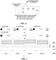
- a base station sends downlink control information (DCI) in slot 1 to schedule slot 3 and slot 4 for uplink data transmission.
- DCI downlink control information
- downlink data with a high priority e.g., a downlink data packet of ultra reliable and low latency communication (URLLC) traffic needs to be imminently sent in slot 2, or strong interference is measured, then what the base station should do, how to notify a UE, and how to process the HARQ corresponding to the scheduled data need to be considered to satisfy the traffic requirement.
- URLLC ultra reliable and low latency communication
- LTE long term evolution
- SIB system information block
- uplink and downlink configuration has only 7 predefined configurations.
- the base station After configuring a certain transmission direction, the base station will not change the transmission direction at least for a period.
- enhanced interference management for traffic adaptation eIMTA
- eIMTA enhanced interference management for traffic adaptation
- the uplink and downlink transmission direction is still one of the original fixed 7 configurations.
- the problem of HARQ caused by the sub-frame structure change is solved through eIMTA in a manner of defining a reference configuration.
- SFI Slot format indicator
- Aggregated slot level(#of slots) is proposed as the part of GC PDCCH contents.
- Group common PDCCH will indicate different information that may correspond to different periodicity. Slot type will be indicated in group common PDCCH. It is also supported to indicate the PDSCH starting symbol. However it is not decided if common PDCCH will indicate that starting symbol.
- Another potential dynamic indication in common PDCCH is for the detecting OFDM symbols in control resource set duration. A semi-static control resource set duration should also be configured. The dynamic indication is to further reduce the blind decoding.
- the embodiments of the present disclosure provide a data transmission method to at least solve the problem of cross-link interference in the related art.
- the scope of the invention is defined by appended independent claim 1. Further embodiments are defined in the respective dependent claims.
- a first node configures configuration information of each time unit within a transmission period, where the configuration information includes: a transmission direction and transmission content in each time unit; the configuration information is notified to a second node; and the first node performs data transceiving with the second node according to the configuration information.
- the transmission direction and the transmission content are configured for each time unit, so the problem of cross-link interference is effectively avoided through a combination of a semi-persistent configuration manner and a dynamic (signaling) notification manner.
- FIG. 1 is a flowchart of the data transmission method according to an embodiment of the present disclosure. As shown in FIG. 1 , the method includes steps described below.
- a first node configures configuration information of each time unit within a transmission period.
- the configuration information includes: a transmission direction and transmission content in each time unit.
- the first node notifies the configuration information to a second node.
- the first node performs data transceiving with the second node according to the configuration information.
- the first node configures the configuration information of each time unit within the transmission period, where the configuration information includes: the transmission direction and transmission content in each time unit; the first node notifies the configuration information to the second node; and the first node performs the data transceiving with the second node according to the configuration information.
- the configuration information is configured only for the time units within one transmission period (a certain period). This manner of configuring configuration information for time units within only one transmission period may be referred to as a semi-persistent configuration manner. That is, in this embodiment, the transmission direction and transmission content are configured in the semi-persistent configuration manner for each time unit.
- the first node once the first node configures the configuration information for time units within one transmission period, the first node notifies the configuration information to the second node.
- This notification manner may be regarded as a dynamic notification manner. Therefore, in this embodiment, the problem of cross-link interference can be effectively avoided through a combination of the semi-persistent configuration manner and the dynamic (signaling) notification manner.
- the first node performing the above steps may be a network element on the network side, such as a base station, an evolved base station or a small base station.
- the first node may also be another network element capable of being served a base station, for example, a central node.
- the second node is an equipment on the terminal side, such as a user equipment (UE), a mobile phone and the like, but is not limited thereto.
- UE user equipment
- FIG. 2 is a flowchart of another data transmission method according to the embodiment of the present disclosure. As shown in FIG. 2 , the method includes steps described below.
- the second node performs data transceiving according to the configuration information.
- the time unit may be one of: a sub-frame, a slot, a mini-slot, an orthogonal frequency division multiplexing symbol or an aggregated slot (a slot in 5G).
- a transmission direction within the transmission period is configured.
- the transmission direction includes at least one of: an uplink transmission direction or a downlink transmission direction.
- the transmission period is determined in one of the following manners: configuring the transmission period through operation administration and maintenance; configuring the transmission period through a radio resource control signaling; configuring the transmission period through a physical broadcast channel; notifying the transmission period through a system information block; configuring the transmission period by a media access control unit; or acquiring the transmission period in a random access process.
- the transmission resource for the uplink transmission within the transmission period is configured by: configuring, through the system information block or high-layer signaling, a time unit used for the uplink transmission within the transmission period, and configuring a periodic sounding reference signal for transmission, a physical uplink control channel and a physical random access channel.
- the transmission resource for the downlink transmission within the transmission period is configured by: configuring a time unit fixedly used for the downlink transmission within the transmission period, and configuring a synchronization signal block for transmission, and a periodic channel state information-reference signal for transmission.
- the transmission direction within the transmission period is configured through one of steps described below.
- the transmission direction of each time unit or a potential slot structure of each time unit is semi-persistently configured.
- the transmission direction to be adjusted of the time unit is indicated through dynamic downlink control information.
- the structure of a remaining flexible-resource part of each slot within the transmission period is configured and notified through DCI.
- the structure indicates at least the transmission direction of the remaining resource part of each slot within the transmission period.
- the transmission direction within the transmission period is notified through a group common physical downlink control channel or a common.
- the time unit whose transmission direction changes is notified to a scheduled second node through UE-specific downlink control information. This corresponding to the claimed step.
- the structures of a current time unit and one or more time units next to the current time unit are notified in a license assisted access manner.
- the first symbol or first two symbols of each time unit are determined to be used for the downlink transmission, and the last symbol or last two symbols of each time unit are determined to be used for the uplink transmission.
- a candidate time-unit structure is semi-persistently configured, and an index of the structure is notified through a group common physical downlink control channel or media access control unit.
- the group common physical downlink control channel is sent to a group of second nodes.
- Each group of second nodes is classified in one of the following manners: being classified according to geographical positions; being classified according to beams; being classified according to sizes of traffic volumes; being classified according to resources; or being classified according to coverage ranges.
- the group identity information of the group common physical downlink control channel is acquired in an initial access process, or configured through radio resource control signaling or a media access control unit.
- the slot structure when each slot has the uplink control information, the downlink control information and the group common physical downlink control channel and the structure of each slot is the same, the structures of a plurality of slots are semi-persistently configured, and aggregation classes of the plurality of slots are determined through the group common physical downlink control channel.
- configuration information about the slot aggregation is used for transmitting a transmission block or for retransmitting a code block group; or a part is used for ultra reliable and low latency communication traffic, and the other part except the part for ultra reliable and low latency communication traffic is used for retransmitting the code block group.
- the first node performs the data transceiving with the second node according to the configuration information through steps described below.
- the first node performs the data transceiving with the second node according to the configuration information as follows: for dynamic time-division duplexing, when the uplink and downlink attribute of a slot where original acknowledgement/non-acknowledgement feedback is located changes so that the original acknowledgement/non-acknowledgement feedback cannot be transmitted, the original acknowledgement/non-acknowledgement is processed in one of the following manners: being discarded; being transmitted with acknowledgement/non-acknowledgement of a next slot in a manner of channel selection or multiplexing; configuring and feeding back all acknowledgement/non-acknowledgement feedback according to a reference uplink and downlink transmission direction; being successively delayed; or providing a new slot position or symbol position for the acknowledgement/non-acknowledgement feedback in downlink control information.
- the configuration information is generated through semi-persistent configuration and dynamic configuration.
- the second node performs the data transceiving according to the configuration information as follows: when semi-persistently configured information and dynamically configured information conflict, the second node determines the transmission direction and the transmission content according to the latest received dynamic downlink control information signaling or configured priority of information to be transmitted.
- the second node determines the transmission direction and the transmission content according to the latest received dynamic downlink control information signaling or the configured priority of the information to be transmitted in one of the following manners.
- a scheduled second node transmits data according to a latest scheduling signaling or slot format, and punches, according to semi-persistently configured signaling, at the transmission position of an original reference signal different in direction to discard data in uplink or downlink transmission at the punched position.
- Dynamic adjustment of the transmission position of an aperiodic reference signal is indicated.
- the indication is performed through UE-specific downlink control information.
- the indication is performed through a group common physical downlink control channel.
- downlink control information is adopted again to schedule a new resource, or the ending of current transmission is indicated.
- transmission data is reserved for a zero power-channel state information-reference signal.
- the transmission direction and the transmission content are determined according to pre-configured information or specific downlink control information.
- the computer software product is stored in a storage medium (such as a read-only memory (ROM)/random access memory (RAM), a magnetic disk or an optical disk) and includes several instructions for enabling a terminal device (which may be a mobile phone, a computer, a server, a network device or the like) to execute the method according to each embodiment of the present disclosure.
- a storage medium such as a read-only memory (ROM)/random access memory (RAM), a magnetic disk or an optical disk
- a terminal device which may be a mobile phone, a computer, a server, a network device or the like
- a data transmission apparatus is further provided in this embodiment.
- the apparatus is used for implementing the above-mentioned embodiments and preferred implementation modes, and repetition will not be made about what has been described.
- the term "module” may be software, hardware or a combination thereof capable of implementing predetermined functions.
- the apparatus in the embodiments described below is preferably implemented by software, but implementation by hardware or by a combination of software and hardware is also possible and conceived.
- FIG. 3 is a structural block diagram of a data transmission apparatus according to an embodiment of the present disclosure.
- the apparatus is applied to a base station.
- the apparatus includes a configuration module 30, a notification module 32 and a communication module 34.
- the configuration module 30 is configured to configure configuration information of each time unit within a period.
- the configuration information includes: a transmission direction and transmission content in each time unit.
- the data transmission apparatus shown in FIG. 3 may be a network element at the network side, such as a base station, an evolved base station and a small base station; the apparatus may also be another network element capable of being served as a base station, for example, a central node.
- FIG. 4 is a structural block diagram of another data transmission apparatus according to an embodiment of the present disclosure.
- the apparatus is applied to a UE.
- the apparatus includes a reception module 40 and a communication module 42.
- This embodiment is an optional embodiment according to the present disclosure. A detailed description of the present application is given below in conjunction with specific implementation modes.
- the transmission direction of the remaining symbol is indicated according to the inherent attribute of the remaining symbol.
- the offset of a scheduled PUSCH from the last symbol of a scheduled DCI is indicated through UE-specific uplink (UL) grant. That is, the starting position of the scheduled PUSCH is indicated through the UL grant to be the last symbol position of the scheduled DCI. It can be understood that the length of the PUSCH in this solution may be semi-persistently configured or dynamically indicated.
- the starting position of the reference signal is the starting symbol position of a data channel; and the offset of the reference signal, that is, the length of the reference signal, is semi-persistently configured or dynamically indicated according to an actual condition.
- symbols other than the PUSCH, PDSCH and reference signal are set to gap (null) by default.
- Manner 6 Several slot structures are predefined or semi-persistently configured according to deployment or application scenes, and then a base station notifies the slot structures to a terminal through the group common PDCCH, or notifies the slot structures to the terminal through a media access control (MAC) control element (CE).
- MAC media access control
- Case 1 Certain slots or mini-slots are semi-persistently configured to be used for uplink transmission, and the uplink transmission needs to be dynamically adjusted to be downlink transmission due to URLLC traffic.
- the transmission of periodic signals is affected, for example, the transmission of the periodic channel state information-reference signal (CSI-RS), sounding reference signal (SRS), synchronization signal block (SS block), semi-persistent scheduling (SPS) and grant-free resource are affected.
- CSI-RS channel state information-reference signal
- SRS sounding reference signal
- SS block synchronization signal block
- SPS semi-persistent scheduling
- grant-free resource are affected.
- a scheduled UE transmits the PDSCH/PUSCH according to the latest scheduling signaling or slot format, and punches, according to the semi-persistently configured signaling, at a transmission position of the reference signal whose direction is different from the original direction. Then data transmitted at the punched position is discarded during uplink data transmission or downlink data transmission.
- the periodic CSI-RS is transmitted by default, and the periodic SRS and periodic CSI/beam related feedbacks are not transmitted; and when the direction is indicated to be uplink, the periodic CSI-RS is not transmitted, and the periodic SRS and periodic CSI/beam feedbacks are transmitted.
- Adjustment of the transmission position of an aperiodic reference signal is indicated dynamically.
- the indication is performed through UE-specific DIC.
- the indication is performed through a common PDCCH to facilitate measurement.
- DCI is adopted again to schedule a new resource, or the ending of current transmission is indicated.
- Zero power-channel state information-reference signal ZP-CSI-RS
- no punching needs to be performed.
- Case 4 For a semi-persistently configured resource for grant-free transmission, or for multi-slot PDSCH reception, or for multi-slot PUSCH/PUCCH transmission, when new DCI received is URLLC, processing is performed according to the solution described below.
- Manner 2 Several slot structures are predefined or semi-persistently configured according to deployment or application scenes, and then notified through the group common PDCCH.
- Each symbol may be UL, DL, blank and sidelink. If each case is supported, the signaling overhead will be large, and thus the indication manner, i.e., this Manner 2, may be used to save signaling overhead.
- the indication manner i.e., this Manner 2
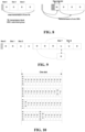
- FIG. 10 is a schematic diagram of the slot configuration structures according to the embodiment of the present disclosure.
- Downlink symbols configured in the middle are used for sending downlink control information to indicate the multiplexing of eMBB and URLLC.
- Manner 3 the granularity of allocation changes from a sub-frame to a symbol in a LAA manner.
- Manner 4 The resource of a physical downlink control channel is acquired through blind detection of UE, UE-specific DCI indicates the starting symbol position of a scheduled PDSCH/PUSCH, and the symbol position of a short PUCCH is semi-persistently configured.
- This instance describes a data transmission method according to the embodiment of the present disclosure on a terminal side.
- a terminal receives a transmission period, in the uplink and downlink transmission directions, determined by the base-station side. Specifically, on the base-station side, the transmission period in the transmission direction is configured through RRC signaling, or configured through a broadcast PBCH, or notified through a SIB, or acquired through a random access process or from MAC CE configuration.
- a base station notifies the transmission period to the terminal, and the terminal receives the transmission period.
- information received by the terminal further includes the transmission direction and the transmission content in addition to the transmission period.
- the terminal determines the transmission directions and transmission content of certain one or more transmission units according to some information about the slot structure within the transmission period sent from the base station. That is, the terminal determines the transmission directions and transmission contents of the transmission units for uplink and downlink transmission according to the indication from the base-station side.
- a UE Based on this information, a UE performs PRACH random access, reception of system information, sending and measurement of a reference signal, and channel estimation on a determined resource (in transmission unit specified by a terminal).
- the terminal receives the configuration information such that the terminal starts blind detection, on the first OFDM symbol of a downlink slot or an uplink dominant slot or a downlink dominant slot, of common downlink control information, group common downlink control information and specific downlink control information.
- the configuration information is determined to be received.
- Uplink traffic data is sent and downlink traffic data is received according to specific scheduling information and high-layer semi-persistently configured information. Specifically, the terminal transmits uplink and downlink traffic data according to the received configuration information.
- one scheduled transmission block TB may be transmitted in multiple slots, then when one of the multiple slots has a transmission error, only the content of the one slot is retransmitted during the next retransmission, and the content of other slots without a transmission error does not need to be retransmitted.
- the terminal processes data according to some rules.
- the particular rules are as shown in Table 1 according to embodiment 3 above.
- This instance describes the case of multiple-slot aggregation scheduling.
- the base station sends scheduling information.
- a schematic diagram illustrating that when the scheduling information indicates that one transmission block (TB) is transmitted in four slots is as shown in FIG. 11.
- FIG. 11 is the schematic diagram illustrating that the base station sends the scheduling information indicating that the one TB is transmitted in the four slots according to an embodiment of the present disclosure, where the one TB is initially transmitted in the four slots that is, two CBGs. Processing of a particular feedback and retransmission combined with dynamic TDD is described below.
- FIG. 12 is a schematic diagram illustrating that URLLC data is transmitted or a new TB is scheduled in a remaining slot according to an embodiment of the present disclosure.
- FIG. 13 is a schematic diagram of performing scheduling retransmission through a mini-slot when one CBG has a transmission error according to an embodiment of the present disclosure.
- multi-slot scheduling information is designed as described below.
- the content of downlink control information is classified into three types.
- the content of DCI is common for all CBGs (this part of the DCI content is identical for the all CBGs).
- An MCS and a resource allocation indication bit field are included.
- the content of DCI is independent for each CBG (this part of the DCI content is different for each CBG).
- a new data indicator (NDI)/ACK/NACK and a HARQ process index indication bit field are included.
- Example 2 One DCI schedules one of multiple CBGs in one TB, and the one TB is scheduled through multiple pieces of DCI information.
Landscapes
- Engineering & Computer Science (AREA)
- Signal Processing (AREA)
- Computer Networks & Wireless Communication (AREA)
- Mobile Radio Communication Systems (AREA)
Claims (12)
- Datenübertragungsverfahren, das Folgendes umfasst:Konfigurieren von Konfigurationsinformationen jeder Zeiteinheit innerhalb einer Übertragungsperiode (S102) durch einen ersten Knoten, wobei die Konfigurationsinformationen umfassen: eine Schlitzstruktur jeder Zeiteinheit;Benachrichtigung eines zweiten Knotens (S104) durch den ersten Knoten über die Konfigurationsinformationen; undDurchführen einer Datenübertragung zwischen dem ersten Knoten und dem zweiten Knoten durch den ersten Knoten gemäß den Konfigurationsinformationen (S106);wobei das Konfigurieren von Konfigurationsinformationen jeder Zeiteinheit innerhalb einer Übertragungsperiode (S102) umfasst:die Bestimmung des Übertragungszeitraums;Konfigurieren einer Übertragungsressource für die Uplink-Übertragung innerhalb der Übertragungsperiode und Konfigurieren einer Übertragungsressource für die Downlink-Übertragung innerhalb der Übertragungsperiode; undKonfigurieren der Schlitzstruktur innerhalb der Übertragungsperiode, wobei die Schlitzstruktur mindestens eines der folgenden Elemente umfasst: eine Aufwärtsstrecken-Schlitzstruktur oder eine Abwärtsstrecken-Schlitzstruktur;
wobei
das Konfigurieren der Schlitzstruktur innerhalb der Übertragungsperiode und das Mitteilen der Konfigurationsinformationen an einen zweiten Knoten umfassen : Benachrichtigen der Schlitzstruktur jeder Zeiteinheit innerhalb der Übertragungsperiode über einen gruppengemeinsamen physikalischen Abwärtsstrecken-Steuerkanal, der Anzeigeinformationen zum Anzeigen einer verworfenen Ressource für einen extrem zuverlässigen und latenzarmen Kommunikationsverkehr trägt, und Benachrichtigen des zweiten Knotens über UE-spezifische Abwärtsstrecken-Steuerinformationen über eine Zeiteinheit, deren Schlitzstruktur geändert wird. - Verfahren nach Anspruch 1, wobei die Übertragungsdauer auf eine der folgenden Weisen bestimmt wird:die Konfiguration des Übertragungszeitraums durch Betriebsverwaltung und Wartung; Konfigurieren der Übertragungsdauer durch eine Funkressourcensteuerungssignalisierung;Konfiguration des Übertragungszeitraums über einen physischen Rundfunkkanal; Mitteilung des Übertragungszeitraums durch einen Systeminformationsblock; Konfigurieren des Übertragungszeitraums durch eine Medienzugriffskontrolleinheit; oderErfassen des Übertragungszeitraums in einem Zufallszugriffsverfahren.
- Verfahren nach Anspruch 1, wobei das Konfigurieren einer Übertragungsressource für die Aufwärtsübertragung innerhalb der Übertragungsperiode umfasst:
Konfigurieren einer Zeiteinheit, die für die Uplink-Übertragung innerhalb der Übertragungsperiode verwendet wird, eines periodisch klingenden Referenzsignals für die Übertragung, eines physikalischen Uplink-Steuerkanals und eines physikalischen Zufallszugriffskanals durch einen Systeminformationsblock oder eine Signalisierung auf hoher Ebene. - Verfahren nach Anspruch 1, wobei das Konfigurieren einer Übertragungsressource für die Downlink-Übertragung innerhalb der Übertragungsperiode umfasst:
Konfigurieren einer Zeiteinheit, die fest für die Downlink-Übertragung innerhalb der Übertragungsperiode verwendet wird; eine Zeiteinheit zum Übertragen eines Synchronisationssignalblocks und Übertragen eines periodischen Kanalzustandsanzeige-Referenzsignals. - Verfahren nach Anspruch 1, wobei die halbpermanent konfigurierte Kandidaten-Zeiteinheitsstruktur über den gruppengemeinsamen physikalischen Downlink-Kontrollkanal an eine Gruppe von zweiten Knoten gesendet wird und die Gruppe der zweiten Knoten durch zweite Knoten gebildet wird, die in der Lage sind, die von einem gleichen gruppengemeinsamen physikalischen Downlink-Kontrollkanal gesendete Zeiteinheitsstruktur auf mindestens eine der folgenden Weisen zu empfangen:die durch Klassifizierung der zweiten Knoten nach geografischen Positionen gebildet werden;die durch Klassifizierung der zweiten Knoten nach Strahlen gebildet werden die durch Klassifizierung der zweiten Knoten nach der Größe des Verkehrsaufkommens gebildet werden;durch Klassifizierung der zweiten Knoten nach Ressourcen gebildet wird; oderdie durch Klassifizierung der zweiten Knoten nach Erfassungsbereichen gebildet werden.
- Verfahren nach Anspruch 1, wobei der gemeinsame physikalische Abwärtsverbindungs-Kontrollkanal der Gruppe, über den die semi-persistent konfigurierte Kandidaten-Zeiteinheit-Struktur gesendet wird, vorbestimmte Gruppenidentitätsinformationen aufweist, wobei die Gruppenidentitätsinformationen in einem anfänglichen Zugriffsprozess erworben oder durch Funkressourcen-Kontrollsignalisierung oder eine Medienzugriffssteuerungseinheit konfiguriert werden.
- Verfahren nach Anspruch 1, wobei die Konfigurationsinformation eine Schlitzstruktur mit Schlitzaggregation und flexiblem Duplexing kombiniert umfasst.
- Verfahren nach Anspruch 7, wobei die Schlitzstruktur eines der das Folgenden umfasst:jeder Schlitz umfasst Aufwärtsstrecken-Steuerinformationen, Abwärtsstrecken-Steuerinformationen und einen gemeinsamen physikalischen Abwärtsstrecken-Steuerkanal, und die Struktur jedes Schlitzes ist gleich;nur ein erster aggregierter Slot die Abwärtsstrecken-Kontrollinformationen enthält und nur ein letzter aggregierter Slot die Aufwärtsstrecken-Kontrollinformationen enthält; oderjeder Slot umfasst die Uplink-Kontrollinformationen, die Downlink-Kontrollinformationen und den gemeinsamen physikalischen Downlink-Kontrollkanal der Gruppe, und die Struktur jedes Slots ist unterschiedlich.
- Verfahren nach Anspruch 7, wobei als Reaktion auf die Feststellung, dass in der Schlitzstruktur nur der erste aggregierte Schlitz die Abwärtsverbindungs-Steuerinformationen und nur der letzte aggregierte Schlitz die Aufwärtsverbindungs-Steuerinformationen umfasst, eine Aggregationsklasse und eine Ressourcenposition des gruppengemeinsamen physikalischen Abwärtsverbindungs-Steuerkanals in einer Art semi-persistenter Funkressourcen-Steuersignalisierungskonfiguration konfiguriert werden.
- Verfahren nach Anspruch 7, wobei als Reaktion auf die Feststellung, dass in der Schlitzstruktur jeder Schlitz Aufwärtsstrecken-Steuerinformationen, Abwärtsstrecken-Steuerinformationen und den gemeinsamen physikalischen Abwärtsstrecken-Steuerkanal der Gruppe umfasst, die Schlitzstruktur durch den ersten Knoten semi-persistent durch Signalisierung auf hoher Ebene konfiguriert wird, wobei die Schlitzstruktur in einer Bitmap-Anzeigeweise durch den gemeinsamen physikalischen Abwärtsstrecken-Steuerkanal der Gruppe konfiguriert wird, und die Anzeigeweise zum Anzeigen einer Struktur jedes Schlitzes unter den aggregierten Schlitzen und zum Anzeigen, dass die Struktur jedes Schlitzes unterschiedlich ist, verwendet wird.
- Verfahren nach Anspruch 1, wobei das Durchführen von Datenübertragungen zwischen einem ersten Knoten und dem zweiten Knoten gemäß den Konfigurationsinformationen (S106) umfasst:
als Reaktion auf die Feststellung, dass die semi-persistente Konfigurationsplanung und die hybride automatische Gruppen-Wiederholungsanforderungs-Bestätigungs-Rückmeldung innerhalb der Zeitsteuerungszeit zurückgeführt werden, wenn die Schlitzstruktur eines Schlitzes geändert wird, werden die in einer ursprünglichen Struktur übertragenen Daten auf eine der folgenden Weisen verarbeitet:verworfen werden;in einer freien Ressource in einem nächsten Zeitschlitz mit derselben Zeitschlitzstruktur übertragen werden, wenn der nächste Zeitschlitz die freie Ressource hat;wenn eine Frequenzposition, an der der zweite Knoten in dem Schlitz eingeplant ist, die gleiche ist wie die Frequenzposition, an der der zweite Knoten in einem nächsten Schlitz mit der gleichen Schlitzstruktur eingeplant ist, Durchführen von Mehrbenutzermultiplexing durch den zweiten Knoten an der Frequenzposition in dem nächsten Schlitz mit der gleichen Schlitzstruktur, um die Daten zu übertragen;eine neue Datenübertragungsposition anzuzeigen;Vorkonfiguration von zwei Zeitbereichspositionen bei der anfänglichen Planung und Senden der Daten an einer ersten verfügbaren Zeitbereichsposition; oderfür den zweiten Knoten, der einen aktuellen Schlitz einplant, eine Abtastung einer Frequenzbereichsressource durchführt, die für ein erstes orthogonales Frequenzmultiplexsymbol in einem nächsten Schlitz mit derselben Schlitzstruktur eingeplant ist, und die Daten überträgt, wenn die Abtastung erfolgreich ist, während die Übertragung aufgegeben oder die Übertragung in einem Modulations- und Kodierungsschema oder mit einer Leistung durchgeführt wird, die niedriger als ein vorgegebener Schwellenwert ist, wenn die Abtastung fehlschlägt. - Verfahren nach Anspruch 1, wobei jede Zeiteinheit eines der folgenden Elemente umfasst:
ein Sub-Frame, ein Slot, ein Mini-Slot, ein Orthogonal-Frequency-Division-Multiplexing-Symbol oder ein aggregierter Slot.
Applications Claiming Priority (2)
| Application Number | Priority Date | Filing Date | Title |
|---|---|---|---|
| CN201710313815.9A CN108811120B (zh) | 2017-05-05 | 2017-05-05 | 数据传输方法及装置 |
| PCT/CN2018/085305 WO2018202032A1 (zh) | 2017-05-05 | 2018-05-02 | 数据传输方法、装置、存储介质及处理器 |
Publications (3)
| Publication Number | Publication Date |
|---|---|
| EP3621382A1 EP3621382A1 (de) | 2020-03-11 |
| EP3621382A4 EP3621382A4 (de) | 2020-12-30 |
| EP3621382B1 true EP3621382B1 (de) | 2025-07-02 |
Family
ID=64015848
Family Applications (1)
| Application Number | Title | Priority Date | Filing Date |
|---|---|---|---|
| EP18794377.4A Active EP3621382B1 (de) | 2017-05-05 | 2018-05-02 | Datenübertragungsverfahren und .vorrichtung, speichermedium und prozessor |
Country Status (4)
| Country | Link |
|---|---|
| US (1) | US11239974B2 (de) |
| EP (1) | EP3621382B1 (de) |
| CN (1) | CN108811120B (de) |
| WO (1) | WO2018202032A1 (de) |
Cited By (1)
| Publication number | Priority date | Publication date | Assignee | Title |
|---|---|---|---|---|
| US20240080168A1 (en) * | 2021-03-16 | 2024-03-07 | Qualcomm Incorporated | Multiple time domain patterns for selection |
Families Citing this family (39)
| Publication number | Priority date | Publication date | Assignee | Title |
|---|---|---|---|---|
| WO2019063188A1 (en) | 2017-09-29 | 2019-04-04 | Sony Corporation | METHODS, INFRASTRUCTURE EQUIPMENT AND COMMUNICATION DEVICE |
| CN110167170B (zh) * | 2018-02-13 | 2023-01-13 | 华为技术有限公司 | 通信方法、装置和系统 |
| CN110708750B (zh) * | 2018-07-09 | 2021-06-22 | 华为技术有限公司 | 一种功率调整方法、终端及存储介质 |
| EP3847846B1 (de) * | 2018-09-07 | 2025-01-29 | Sierra Wireless, ULC | Verfahren und vorrichtungen für kleine datenübertragungen |
| US11991690B2 (en) * | 2018-09-07 | 2024-05-21 | Lenovo (Beijing) Limited | Method and apparatus for flexible transmission on unlicensed spectrum |
| CN109565650B (zh) | 2018-11-15 | 2021-08-31 | 北京小米移动软件有限公司 | 同步信号块的配置信息的广播、接收方法和装置 |
| CN111246587B (zh) * | 2018-11-29 | 2021-10-19 | 华为技术有限公司 | 传输方法和装置 |
| CN111356243B (zh) * | 2018-12-21 | 2023-08-11 | 中兴通讯股份有限公司 | 数据的传输方法、装置、存储介质及电子装置 |
| CN112262607B (zh) * | 2018-12-26 | 2024-03-05 | Oppo广东移动通信有限公司 | 一种dmrs配置方法、终端设备及网络设备 |
| CN111278056A (zh) * | 2019-01-02 | 2020-06-12 | 维沃移动通信有限公司 | 信息传输方法、终端及网络设备 |
| EP3681233B1 (de) * | 2019-01-10 | 2022-06-15 | Panasonic Intellectual Property Corporation of America | Sendeempfängervorrichtung und planungsvorrichtung |
| CN111432349B (zh) * | 2019-01-10 | 2021-10-15 | 华为技术有限公司 | 一种通信方法及装置 |
| CN111436123B (zh) * | 2019-01-11 | 2023-06-23 | 华为技术有限公司 | 一种通信方法及装置 |
| CN111263450B (zh) * | 2019-01-11 | 2022-09-30 | 维沃移动通信有限公司 | Pdcch监测方法、装置、终端、基站和存储介质 |
| CN112586031A (zh) * | 2019-01-11 | 2021-03-30 | Oppo广东移动通信有限公司 | 无线通信方法和终端 |
| CN111435894B (zh) * | 2019-01-11 | 2023-07-14 | 中兴通讯股份有限公司 | 资源配置的方法及装置、存储介质及电子装置 |
| CN111526588B (zh) | 2019-02-02 | 2023-05-12 | 华为技术有限公司 | 确定传输资源的方法和装置 |
| CN111585692B (zh) * | 2019-02-15 | 2021-10-26 | 华为技术有限公司 | 初始信号检测方法、装置 |
| US11497042B2 (en) * | 2019-02-15 | 2022-11-08 | Qualcomm Incorporated | Resource scheduling techniques in wireless systems |
| SG11202109985UA (en) * | 2019-03-11 | 2021-10-28 | Beijing Xiaomi Mobile Software Co Ltd | Transmission indication method and apparatus |
| CN111294127B (zh) * | 2019-03-29 | 2022-03-18 | 北京紫光展锐通信技术有限公司 | 基于同步资源的数据传输方法及装置、存储介质、用户设备 |
| AU2019462295B2 (en) * | 2019-08-16 | 2023-10-26 | Huawei Technologies Co., Ltd. | Transmission resource configuration method and device |
| US20210076111A1 (en) * | 2019-09-05 | 2021-03-11 | Ciena Corporation | Flexible Ethernet over wireless links |
| CN114389761A (zh) * | 2019-09-18 | 2022-04-22 | 上海朗帛通信技术有限公司 | 一种被用于无线通信的节点中的方法和装置 |
| WO2021056593A1 (zh) * | 2019-09-29 | 2021-04-01 | 华为技术有限公司 | 通信方法、设备及系统 |
| EP4044707A4 (de) * | 2019-09-30 | 2022-11-09 | Huawei Technologies Co., Ltd. | Dynamische ressourcenanzeigeverfahren und -vorrichtung |
| WO2021163929A1 (zh) * | 2020-02-19 | 2021-08-26 | 华为技术有限公司 | 业务传输的方法和通信装置 |
| CN121508777A (zh) * | 2020-04-06 | 2026-02-10 | Tcl通讯(宁波)有限公司 | 通信方法和通信装置 |
| US11558885B2 (en) * | 2020-04-22 | 2023-01-17 | Qualcomm Incorporated | Simultaneous bandwidth part (BWP) switch on multiple cells |
| US12464520B2 (en) | 2020-09-18 | 2025-11-04 | Qualcomm Incorporated | Delayed HARQ-ACK report for SPS |
| WO2022077249A1 (en) * | 2020-10-14 | 2022-04-21 | Lenovo (Beijing) Limited | Ta update during uplink transmission |
| US20220317635A1 (en) * | 2021-04-06 | 2022-10-06 | International Business Machines Corporation | Smart ecosystem curiosity-based self-learning |
| US11991686B2 (en) * | 2021-07-14 | 2024-05-21 | Nokia Technologies Oy | CG/SPS in cross-division duplex |
| EP4271106B1 (de) | 2022-04-28 | 2025-10-15 | Nokia Technologies Oy | Handhabung von querverbindungsinterferenzen bei physikalischen direktzugriffskanalgelegenheiten bei flexiblen/vollduplex-schlitzen |
| CN117042142A (zh) * | 2022-04-29 | 2023-11-10 | 北京紫光展锐通信技术有限公司 | 数据传输方法及装置、计算机可读存储介质 |
| WO2024005621A1 (ko) * | 2022-06-27 | 2024-01-04 | 삼성전자 주식회사 | 무선 통신 시스템에서 xdd(cross division duplex)에 기반하여 신호를 송수신하기 위한 장치 및 방법 |
| US12501420B2 (en) * | 2022-09-23 | 2025-12-16 | Qualcomm Incorporated | Signaling to override radio resource control (RRC) configured direction |
| US20250023614A1 (en) * | 2023-07-14 | 2025-01-16 | Qualcomm Incorporated | Base station information exchange with qos class and/or measurement metrics |
| US20250317876A1 (en) * | 2024-04-04 | 2025-10-09 | Qualcomm Incorporated | Slot format indicator interpretation rules in the presence of adapted synchronization signal blocks |
Family Cites Families (14)
| Publication number | Priority date | Publication date | Assignee | Title |
|---|---|---|---|---|
| WO2011108883A2 (ko) * | 2010-03-05 | 2011-09-09 | 엘지전자 주식회사 | 상향링크 전력을 제어하는 단말 장치 및 그 방법 |
| US8948111B2 (en) * | 2011-10-03 | 2015-02-03 | Qualcomm Incorporated | Uplink resource management under coordinated multipoint transmission |
| US9107191B2 (en) * | 2011-11-11 | 2015-08-11 | Qualcomm Incorporated | System and method for managing simultaneous uplink signal transmissions in carrier aggregation systems |
| CN103220802B (zh) * | 2012-01-19 | 2019-04-05 | 中兴通讯股份有限公司 | 下行数据处理方法及装置 |
| WO2014110783A1 (en) * | 2013-01-18 | 2014-07-24 | Broadcom Corporation | Inter-cell cross-link interference coordination in flexible time division duplex communication |
| CN104105215A (zh) * | 2013-04-02 | 2014-10-15 | 中兴通讯股份有限公司 | 一种数据发送方法和站点设备 |
| CN104703205A (zh) * | 2013-12-07 | 2015-06-10 | 上海朗帛通信技术有限公司 | 一种网络辅助干扰消除的方法和装置 |
| US9577778B2 (en) * | 2014-02-24 | 2017-02-21 | Intel Corporation | Interference reduction using hybrid signaling |
| JP6785664B2 (ja) * | 2015-01-28 | 2020-11-18 | シャープ株式会社 | 端末装置、基地局装置および方法 |
| US10841946B2 (en) * | 2015-08-31 | 2020-11-17 | Ntt Docomo, Inc. | User terminal, radio base station, and radio communication method |
| CN106255207B (zh) * | 2015-08-31 | 2019-11-01 | 北京智谷技术服务有限公司 | 上行资源配置方法、上行传输方法、及其装置 |
| CN108605348B (zh) * | 2016-02-05 | 2022-02-08 | 三星电子株式会社 | 移动通信系统中的通信方法和设备 |
| US20200068556A1 (en) * | 2016-11-03 | 2020-02-27 | Nokia Technologies Oy | Communication system |
| RU2730967C1 (ru) * | 2017-04-21 | 2020-08-26 | Хуавей Текнолоджиз Ко., Лтд. | Устройство и способ конфигурирования направления передачи частотно-временного ресурса |
-
2017
- 2017-05-05 CN CN201710313815.9A patent/CN108811120B/zh active Active
-
2018
- 2018-05-02 US US16/610,987 patent/US11239974B2/en active Active
- 2018-05-02 WO PCT/CN2018/085305 patent/WO2018202032A1/zh not_active Ceased
- 2018-05-02 EP EP18794377.4A patent/EP3621382B1/de active Active
Cited By (1)
| Publication number | Priority date | Publication date | Assignee | Title |
|---|---|---|---|---|
| US20240080168A1 (en) * | 2021-03-16 | 2024-03-07 | Qualcomm Incorporated | Multiple time domain patterns for selection |
Also Published As
| Publication number | Publication date |
|---|---|
| CN108811120A (zh) | 2018-11-13 |
| EP3621382A1 (de) | 2020-03-11 |
| WO2018202032A1 (zh) | 2018-11-08 |
| US11239974B2 (en) | 2022-02-01 |
| CN108811120B (zh) | 2023-05-02 |
| EP3621382A4 (de) | 2020-12-30 |
| US20200177341A1 (en) | 2020-06-04 |
Similar Documents
| Publication | Publication Date | Title |
|---|---|---|
| EP3621382B1 (de) | Datenübertragungsverfahren und .vorrichtung, speichermedium und prozessor | |
| US12133223B2 (en) | Uplink control information transmitting method and apparatus | |
| US11863313B2 (en) | Data transmission method, base station, user equipment, and system | |
| US11729793B2 (en) | Scheduling uplink transmissions | |
| US10314037B2 (en) | Latency reduction techniques in wireless communications | |
| CN108271430B (zh) | 用于在非授权频带中发送上行链路信号的方法和终端 | |
| CN105580457B (zh) | 确定上行链路发送定时的方法及使用该方法的用户设备 | |
| US20220015129A1 (en) | Radio access node, communication terminal and methods performed therein | |
| CN111884770B (zh) | Harq-ack码本产生方法 | |
| JP2019520734A (ja) | アップリンク制御情報を伝送するための方法および装置 | |
| WO2014116078A1 (ko) | 무선 통신 시스템에서 단말의 통신 방법 및 장치 | |
| JP2018533304A (ja) | 1セグメントpucchフォーマット | |
| EP3386254B1 (de) | Verfahren zur trägerübergreifenden planung, und vorrichtungen | |
| US20250008549A1 (en) | Method and device for transmitting sidelink resource coordination information | |
| US10880053B2 (en) | Wireless device, a network node and methods therein for handling transmissions in a wireless communications network | |
| KR20160134497A (ko) | 면허 및 비면허 대역을 지원하는 네트워크에서 통신 노드의 동작 방법 |
Legal Events
| Date | Code | Title | Description |
|---|---|---|---|
| STAA | Information on the status of an ep patent application or granted ep patent |
Free format text: STATUS: THE INTERNATIONAL PUBLICATION HAS BEEN MADE |
|
| PUAI | Public reference made under article 153(3) epc to a published international application that has entered the european phase |
Free format text: ORIGINAL CODE: 0009012 |
|
| STAA | Information on the status of an ep patent application or granted ep patent |
Free format text: STATUS: REQUEST FOR EXAMINATION WAS MADE |
|
| 17P | Request for examination filed |
Effective date: 20191127 |
|
| AK | Designated contracting states |
Kind code of ref document: A1 Designated state(s): AL AT BE BG CH CY CZ DE DK EE ES FI FR GB GR HR HU IE IS IT LI LT LU LV MC MK MT NL NO PL PT RO RS SE SI SK SM TR |
|
| AX | Request for extension of the european patent |
Extension state: BA ME |
|
| DAV | Request for validation of the european patent (deleted) | ||
| DAX | Request for extension of the european patent (deleted) | ||
| A4 | Supplementary search report drawn up and despatched |
Effective date: 20201127 |
|
| RIC1 | Information provided on ipc code assigned before grant |
Ipc: H04W 72/04 20090101AFI20201123BHEP |
|
| STAA | Information on the status of an ep patent application or granted ep patent |
Free format text: STATUS: EXAMINATION IS IN PROGRESS |
|
| 17Q | First examination report despatched |
Effective date: 20230103 |
|
| REG | Reference to a national code |
Ref country code: DE Ref legal event code: R079 Ipc: H04W0072044600 Ref country code: DE Ref legal event code: R079 Ref document number: 602018083223 Country of ref document: DE Free format text: PREVIOUS MAIN CLASS: H04W0072040000 Ipc: H04W0072044600 |
|
| GRAP | Despatch of communication of intention to grant a patent |
Free format text: ORIGINAL CODE: EPIDOSNIGR1 |
|
| STAA | Information on the status of an ep patent application or granted ep patent |
Free format text: STATUS: GRANT OF PATENT IS INTENDED |
|
| RIC1 | Information provided on ipc code assigned before grant |
Ipc: H04L 5/00 20060101ALI20250217BHEP Ipc: H04W 72/0446 20230101AFI20250217BHEP |
|
| INTG | Intention to grant announced |
Effective date: 20250311 |
|
| GRAS | Grant fee paid |
Free format text: ORIGINAL CODE: EPIDOSNIGR3 |
|
| GRAA | (expected) grant |
Free format text: ORIGINAL CODE: 0009210 |
|
| STAA | Information on the status of an ep patent application or granted ep patent |
Free format text: STATUS: THE PATENT HAS BEEN GRANTED |
|
| AK | Designated contracting states |
Kind code of ref document: B1 Designated state(s): AL AT BE BG CH CY CZ DE DK EE ES FI FR GB GR HR HU IE IS IT LI LT LU LV MC MK MT NL NO PL PT RO RS SE SI SK SM TR |
|
| REG | Reference to a national code |
Ref country code: GB Ref legal event code: FG4D |
|
| REG | Reference to a national code |
Ref country code: CH Ref legal event code: EP |
|
| REG | Reference to a national code |
Ref country code: DE Ref legal event code: R096 Ref document number: 602018083223 Country of ref document: DE |
|
| REG | Reference to a national code |
Ref country code: IE Ref legal event code: FG4D |
|
| REG | Reference to a national code |
Ref country code: NL Ref legal event code: MP Effective date: 20250702 |
|
| PG25 | Lapsed in a contracting state [announced via postgrant information from national office to epo] |
Ref country code: PT Free format text: LAPSE BECAUSE OF FAILURE TO SUBMIT A TRANSLATION OF THE DESCRIPTION OR TO PAY THE FEE WITHIN THE PRESCRIBED TIME-LIMIT Effective date: 20251103 |
|
| PG25 | Lapsed in a contracting state [announced via postgrant information from national office to epo] |
Ref country code: NL Free format text: LAPSE BECAUSE OF FAILURE TO SUBMIT A TRANSLATION OF THE DESCRIPTION OR TO PAY THE FEE WITHIN THE PRESCRIBED TIME-LIMIT Effective date: 20250702 |
|
| REG | Reference to a national code |
Ref country code: AT Ref legal event code: MK05 Ref document number: 1810773 Country of ref document: AT Kind code of ref document: T Effective date: 20250702 |
|
| PG25 | Lapsed in a contracting state [announced via postgrant information from national office to epo] |
Ref country code: IS Free format text: LAPSE BECAUSE OF FAILURE TO SUBMIT A TRANSLATION OF THE DESCRIPTION OR TO PAY THE FEE WITHIN THE PRESCRIBED TIME-LIMIT Effective date: 20251102 |
|
| PG25 | Lapsed in a contracting state [announced via postgrant information from national office to epo] |
Ref country code: NO Free format text: LAPSE BECAUSE OF FAILURE TO SUBMIT A TRANSLATION OF THE DESCRIPTION OR TO PAY THE FEE WITHIN THE PRESCRIBED TIME-LIMIT Effective date: 20251002 |
|
| REG | Reference to a national code |
Ref country code: LT Ref legal event code: MG9D |
|
| PG25 | Lapsed in a contracting state [announced via postgrant information from national office to epo] |
Ref country code: AT Free format text: LAPSE BECAUSE OF FAILURE TO SUBMIT A TRANSLATION OF THE DESCRIPTION OR TO PAY THE FEE WITHIN THE PRESCRIBED TIME-LIMIT Effective date: 20250702 |
|
| PG25 | Lapsed in a contracting state [announced via postgrant information from national office to epo] |
Ref country code: FI Free format text: LAPSE BECAUSE OF FAILURE TO SUBMIT A TRANSLATION OF THE DESCRIPTION OR TO PAY THE FEE WITHIN THE PRESCRIBED TIME-LIMIT Effective date: 20250702 |
|
| PG25 | Lapsed in a contracting state [announced via postgrant information from national office to epo] |
Ref country code: HR Free format text: LAPSE BECAUSE OF FAILURE TO SUBMIT A TRANSLATION OF THE DESCRIPTION OR TO PAY THE FEE WITHIN THE PRESCRIBED TIME-LIMIT Effective date: 20250702 |
|
| PG25 | Lapsed in a contracting state [announced via postgrant information from national office to epo] |
Ref country code: GR Free format text: LAPSE BECAUSE OF FAILURE TO SUBMIT A TRANSLATION OF THE DESCRIPTION OR TO PAY THE FEE WITHIN THE PRESCRIBED TIME-LIMIT Effective date: 20251003 |
|
| PG25 | Lapsed in a contracting state [announced via postgrant information from national office to epo] |
Ref country code: SE Free format text: LAPSE BECAUSE OF FAILURE TO SUBMIT A TRANSLATION OF THE DESCRIPTION OR TO PAY THE FEE WITHIN THE PRESCRIBED TIME-LIMIT Effective date: 20250702 Ref country code: CZ Free format text: LAPSE BECAUSE OF FAILURE TO SUBMIT A TRANSLATION OF THE DESCRIPTION OR TO PAY THE FEE WITHIN THE PRESCRIBED TIME-LIMIT Effective date: 20250702 |
|
| PG25 | Lapsed in a contracting state [announced via postgrant information from national office to epo] |
Ref country code: LV Free format text: LAPSE BECAUSE OF FAILURE TO SUBMIT A TRANSLATION OF THE DESCRIPTION OR TO PAY THE FEE WITHIN THE PRESCRIBED TIME-LIMIT Effective date: 20250702 |
|
| PG25 | Lapsed in a contracting state [announced via postgrant information from national office to epo] |
Ref country code: BG Free format text: LAPSE BECAUSE OF FAILURE TO SUBMIT A TRANSLATION OF THE DESCRIPTION OR TO PAY THE FEE WITHIN THE PRESCRIBED TIME-LIMIT Effective date: 20250702 Ref country code: PL Free format text: LAPSE BECAUSE OF FAILURE TO SUBMIT A TRANSLATION OF THE DESCRIPTION OR TO PAY THE FEE WITHIN THE PRESCRIBED TIME-LIMIT Effective date: 20250702 |
|
| PG25 | Lapsed in a contracting state [announced via postgrant information from national office to epo] |
Ref country code: RS Free format text: LAPSE BECAUSE OF FAILURE TO SUBMIT A TRANSLATION OF THE DESCRIPTION OR TO PAY THE FEE WITHIN THE PRESCRIBED TIME-LIMIT Effective date: 20251002 |
|
| PG25 | Lapsed in a contracting state [announced via postgrant information from national office to epo] |
Ref country code: ES Free format text: LAPSE BECAUSE OF FAILURE TO SUBMIT A TRANSLATION OF THE DESCRIPTION OR TO PAY THE FEE WITHIN THE PRESCRIBED TIME-LIMIT Effective date: 20250702 |
|
| PG25 | Lapsed in a contracting state [announced via postgrant information from national office to epo] |
Ref country code: SM Free format text: LAPSE BECAUSE OF FAILURE TO SUBMIT A TRANSLATION OF THE DESCRIPTION OR TO PAY THE FEE WITHIN THE PRESCRIBED TIME-LIMIT Effective date: 20250702 |
|
| PGFP | Annual fee paid to national office [announced via postgrant information from national office to epo] |
Ref country code: GB Payment date: 20260312 Year of fee payment: 9 |
|
| PG25 | Lapsed in a contracting state [announced via postgrant information from national office to epo] |
Ref country code: DK Free format text: LAPSE BECAUSE OF FAILURE TO SUBMIT A TRANSLATION OF THE DESCRIPTION OR TO PAY THE FEE WITHIN THE PRESCRIBED TIME-LIMIT Effective date: 20250702 |
|
| PG25 | Lapsed in a contracting state [announced via postgrant information from national office to epo] |
Ref country code: IT Free format text: LAPSE BECAUSE OF FAILURE TO SUBMIT A TRANSLATION OF THE DESCRIPTION OR TO PAY THE FEE WITHIN THE PRESCRIBED TIME-LIMIT Effective date: 20250702 |