EP3623347A1 - Procédé d'élimination d'un contaminant à partir d'eaux usées provenant d'une installation industrielle et système permettant de mettre en uvre un tel procédé - Google Patents
Procédé d'élimination d'un contaminant à partir d'eaux usées provenant d'une installation industrielle et système permettant de mettre en uvre un tel procédé Download PDFInfo
- Publication number
- EP3623347A1 EP3623347A1 EP18194743.3A EP18194743A EP3623347A1 EP 3623347 A1 EP3623347 A1 EP 3623347A1 EP 18194743 A EP18194743 A EP 18194743A EP 3623347 A1 EP3623347 A1 EP 3623347A1
- Authority
- EP
- European Patent Office
- Prior art keywords
- wastewater
- compartment
- chloride
- osmosis module
- plant
- Prior art date
- Legal status (The legal status is an assumption and is not a legal conclusion. Google has not performed a legal analysis and makes no representation as to the accuracy of the status listed.)
- Withdrawn
Links
Images


Classifications
-
- C—CHEMISTRY; METALLURGY
- C02—TREATMENT OF WATER, WASTE WATER, SEWAGE, OR SLUDGE
- C02F—TREATMENT OF WATER, WASTE WATER, SEWAGE, OR SLUDGE
- C02F1/00—Treatment of water, waste water, or sewage
- C02F1/44—Treatment of water, waste water, or sewage by dialysis, osmosis or reverse osmosis
- C02F1/445—Treatment of water, waste water, or sewage by dialysis, osmosis or reverse osmosis by forward osmosis
-
- C—CHEMISTRY; METALLURGY
- C02—TREATMENT OF WATER, WASTE WATER, SEWAGE, OR SLUDGE
- C02F—TREATMENT OF WATER, WASTE WATER, SEWAGE, OR SLUDGE
- C02F1/00—Treatment of water, waste water, or sewage
- C02F1/44—Treatment of water, waste water, or sewage by dialysis, osmosis or reverse osmosis
-
- C—CHEMISTRY; METALLURGY
- C02—TREATMENT OF WATER, WASTE WATER, SEWAGE, OR SLUDGE
- C02F—TREATMENT OF WATER, WASTE WATER, SEWAGE, OR SLUDGE
- C02F1/00—Treatment of water, waste water, or sewage
- C02F1/46—Treatment of water, waste water, or sewage by electrochemical methods
- C02F1/461—Treatment of water, waste water, or sewage by electrochemical methods by electrolysis
- C02F1/467—Treatment of water, waste water, or sewage by electrochemical methods by electrolysis by electrochemical disinfection; by electrooxydation or by electroreduction
- C02F1/4672—Treatment of water, waste water, or sewage by electrochemical methods by electrolysis by electrochemical disinfection; by electrooxydation or by electroreduction by electrooxydation
- C02F1/4674—Treatment of water, waste water, or sewage by electrochemical methods by electrolysis by electrochemical disinfection; by electrooxydation or by electroreduction by electrooxydation with halogen or compound of halogens, e.g. chlorine, bromine
-
- C—CHEMISTRY; METALLURGY
- C02—TREATMENT OF WATER, WASTE WATER, SEWAGE, OR SLUDGE
- C02F—TREATMENT OF WATER, WASTE WATER, SEWAGE, OR SLUDGE
- C02F1/00—Treatment of water, waste water, or sewage
- C02F1/46—Treatment of water, waste water, or sewage by electrochemical methods
- C02F1/461—Treatment of water, waste water, or sewage by electrochemical methods by electrolysis
- C02F1/467—Treatment of water, waste water, or sewage by electrochemical methods by electrolysis by electrochemical disinfection; by electrooxydation or by electroreduction
- C02F1/4676—Treatment of water, waste water, or sewage by electrochemical methods by electrolysis by electrochemical disinfection; by electrooxydation or by electroreduction by electroreduction
- C02F1/4678—Treatment of water, waste water, or sewage by electrochemical methods by electrolysis by electrochemical disinfection; by electrooxydation or by electroreduction by electroreduction of metals
-
- C—CHEMISTRY; METALLURGY
- C02—TREATMENT OF WATER, WASTE WATER, SEWAGE, OR SLUDGE
- C02F—TREATMENT OF WATER, WASTE WATER, SEWAGE, OR SLUDGE
- C02F2101/00—Nature of the contaminant
- C02F2101/10—Inorganic compounds
- C02F2101/12—Halogens or halogen-containing compounds
-
- C—CHEMISTRY; METALLURGY
- C02—TREATMENT OF WATER, WASTE WATER, SEWAGE, OR SLUDGE
- C02F—TREATMENT OF WATER, WASTE WATER, SEWAGE, OR SLUDGE
- C02F2103/00—Nature of the water, waste water, sewage or sludge to be treated
- C02F2103/34—Nature of the water, waste water, sewage or sludge to be treated from industrial activities not provided for in groups C02F2103/12 - C02F2103/32
-
- C—CHEMISTRY; METALLURGY
- C02—TREATMENT OF WATER, WASTE WATER, SEWAGE, OR SLUDGE
- C02F—TREATMENT OF WATER, WASTE WATER, SEWAGE, OR SLUDGE
- C02F2201/00—Apparatus for treatment of water, waste water or sewage
- C02F2201/46—Apparatus for electrochemical processes
- C02F2201/461—Electrolysis apparatus
-
- C—CHEMISTRY; METALLURGY
- C02—TREATMENT OF WATER, WASTE WATER, SEWAGE, OR SLUDGE
- C02F—TREATMENT OF WATER, WASTE WATER, SEWAGE, OR SLUDGE
- C02F2301/00—General aspects of water treatment
- C02F2301/08—Multistage treatments, e.g. repetition of the same process step under different conditions
Definitions
- This application relates to a novel system and method for treating concentrated industrial fertilizer wastewater using electrolysis, and more particularly nitrophosphate wastewater or wastewater from other mineral or organo-mineral fertilizer processes.
- the goal is to reduce the amount of wastewater being discharged into the environment by recirculating the wastewater effluent back into the industrial system itself.
- the nature of the wastewater may vary depending on the type of fertilizer being produced and the specific processes involved.
- Mineral fertilisers contain one or more primary (major) nutrients nitrogen (N), phosphorus (P) or potassium (K) in inorganic form or as urea or cyanamide.
- the primary nutrients N, P, and K are required by plants in large or moderate amounts.
- mineral fertilisers also contain other nutrients required by plants to a minor degree, such as Ca, Mg, and S. Trace elements required in small quantities are B, Cl, Cu, Fe, Mn, Mo, Zn.
- Fertilizers are classified in terms of their major nutrient contents: straight fertilisers generally contain only one major or primary nutrient (N, P or K) whereas complex fertilizers contain two or more major nutrients (NP, PK or NPK and more particularly NP or NPK fertilizers).
- nitrophosphate process there are two common processes for producing complex fertilizers, namely the mixed acid process and the nitrophosphate process.
- the nitrophosphate process specifically, rock phosphate is initially dissolved in excess nitric acid and Ca(NO 3 ) 2 *4H 2 O is removed from the digested raw phosphate solution by cooling and filtration. Then, by neutralizing the resulting filtrate, a solution containing mainly ammonium nitrate and ammonium calcium phosphates is formed.
- an AN-MAP-DCP (ammonium nitrate - monoammonium phospohate - dicalcium phospohate) slurry-melt is formed, to which may be added potassium chloride/potassium sulphate salts.
- the main effluent components in NP or NPK wastewater are ammonia, nitrate, fluoride, and phosphate, and the wastewater may also contain heavy metals from the phosphate rock, such as Cd, Hg and Zn.
- Recommendation 2 is in line with the abovementioned goal to reduce the amount of wastewater discharged into the environment by recirculating the wastewater effluent back into the industrial system itself. It is of benefit to recirculate nitrogen, phosphorous and potassium containing wastewater to a plant producing NPK fertilizers as this reduces the environmental impact and optimizes the quantities of raw materials and water fed to the production process.
- Chloride is not typically considered as an important contaminant in the wastewater from fertilizer plants. This may be due to the relatively low levels of chloride seen in fertilizer wastewater which may only be on the order of 1000 ppm. For comparison, drinking water has maximum levels of 250 ppm, whereas salt water contains 35,000 ppm sodium chloride, the chloride portion of which is approximately 21,400 ppm. As such, the levels seen in fertilizer wastewater are not generally considered to be an environmental concern.
- safety limits must be respected upon recycling fertilizer wastewater back to the fertilizer solution in the production process. Indeed, at the high temperatures of the granulation step or the evaporation step for subsequent prilling, strict chlorine limits must be observed in order to prevent decomposition of ammonium nitrate and related fire and explosion hazards. Consequently, the level of recycling of the wastewater has to be controlled in order for the chlorine levels to stay below safety limits, in the fertilizer solution prior to the particulation stage.
- the treatment of the wastewater for chlorine removal will introduce additional flexibility with respect to the volumes of wastewater recycled to the process and/or to the chlorine content of the rock phosphate that is fed to the first step of the process.
- Chloride ions are electrolyzed to hypochlorite and the reaction of those hypochlorite ions with the nitrogen compounds results in the production of clean nitrogen gas, CO 2 , and chloride ions.
- the chloride ions can be converted to hypochlorite ions by recirculation of the wastewater back to the electrochemical cell.
- JPS5113007 discloses a treatment for the wastewater of chemical fertilizer plants in two stages.
- CaF 2 is removed in a first electrochemical cell, by adsorption onto diatomaceous earth activated through preliminary electrolysis.
- amines are converted to chloramines by reaction with chlorine and hypochlorite.
- Chlorine and hypochlorite are obtained by separate electrolysis of sea water and the resulting electrolyzed water is added to the second electrochemical cell for treating the fertilizer wastewater.
- electrolysis and adsorption by means of electrolytic active diatomaceous earth promote the stability of chloramines.
- the two stages of treatment incidentally remove PO 4 and SiO 2 .
- WO2017/103041 and WO2017/103042 present methods for treating industrial wastewater and more particularly nitrophosphate fertilizer wastewater or wastewater from other mineral organo-mineral fertilizer processes. Both applications disclose the removal of chloride as chlorine gas by electrolysis of the wastewater. WO2017/103042 further addresses the issue of scaling in the cathode chamber by recirculating the acidic anolyte into the cathode chamber, thereby dissolving the scaling. The applications disclose chloride concentrations as low as 250 ppm after removal from by the electrochemical treatment. WO2017/103042 discloses a Faradaic current efficiency of 8.6%.
- Described herein is a novel concept for removing contaminants from waste water from an industrial plant, in particular fertilizer plant. It has been found that by concentrating the contaminants in the wastewater prior to the electrolysis step the efficiency of the process can be increased considerably.
- a method for removing a contaminant from waste water from an industrial plant. The method comprises the steps of:
- the contaminant is chloride and the chloride concentration of the wastewater after the concentrating step is between 1250 and 2250 ppm, more in particular between 1500 and 2250 ppm and more in particular between 1750 and 2250 ppm..
- the step of concentrating the wastewater is performed by a forward osmosis module or a pressure assisted module, comprising a first compartment and a second compartment separated by a membrane.
- the method comprises a further step of directing the wastewater to the first compartment of the osmosis module and the recirculating step comprises the steps of directing the electrolyzed wastewater to the second compartment of the osmosis module and recirculating the wastewater from the second compartment of the osmosis module to the fertilizer plant.
- the flow of the wastewater in the first compartment of the osmosis module is counter-current with respect to the flow in the second compartment of the osmosis module.
- the method comprises a further step of adding a salt solution to or upstream of the second compartment of the osmosis module is comprised.
- the salt solution added to or upstream of the second compartment of the osmosis module comprises one or more of ammonium nitrate, ammonium calcium phosphates and calcium nitrate .
- the industrial plant is a fertilizer plant, in particular a nitro-phosphate or another mineral, or organo-mineral fertilizer plant and, more in particular, the industrial plant produces compositions comprising ammonium nitrate.
- the contaminant is chloride and the concentration of chloride in the electrolyzed wastewater is less than 350 ppm.
- a system for removing from waste water from an industrial plant a contaminant present in the waste water.
- the system comprises a concentrating unit fluidly connected to the wastewater from the fertilizer plant and an electrochemical treatment unit for removing the contaminant fluidly connected downstream of the concentration unit and fluidly connected to recirculate the treated wastewater to the fertilizer plant.
- the concentrating unit is a forward osmosis module, a pressure assisted osmosis module, a reverse osmosis module, or an electrodialysis module.
- the concentrating unit is a forward or pressure assisted osmosis module comprising a first compartment and a second compartment separated by a membrane.
- the wastewater from the industrial plant to be treated is fluidly connected to the first compartment, the first compartment is fluidly connected to the electrochemical treatment unit and the treated wastewater is fluidly connected to the second compartment and flows through the second compartment to be recirculated to the industrial plant.
- a feed of salt solution is fluidly connected to the second compartment.
- the concentrating unit comprises more than one osmosis module, in particular two or three osmosis modules, connected in series.
- the wastewater flow in the first compartment of the osmosis module flows counter-currently with respect to the flow of the water in the second compartment of the osmosis module.
- a fertilizer plant in particular a nitro-phosphate fertilizer plant, or another mineral or organo-mineral fertilizer plant, more in particular a fertilizer plant producing compositions comprising ammonium nitrate.
- a measurable value such as a parameter, an amount, a time period, and the like
- a measurable value such as a parameter, an amount, a time period, and the like
- the invention is described in detail below for the removal of chloride from fertilizer waste water through formation and removal of chlorine gas from the wastewater.
- the present application can be applied to the removal from any industrial wastewater of any contaminant that can be chemically converted by electrolysis, in order for the wastewater to be recycled back to the industrial plant.
- contaminants are found, for example, in streams including but not limited to, brines which are found in uranium processing, and sodium sulphate electrolysis.
- Examples 3 and 4 describe such applications for non-fertilizers wastewater or recycle streams and Example 6 also describes the increase in the Faradaic current efficiency due to pre-concentration.
- the contaminant forms a gas and is removed in the gas phase during the electrolysis step.
- the Faradaic current efficiency is defined as the percentage of the current provided to the electrolysis cell that is used for converting the contaminant.
- Chloride can be seen in fertilizer wastewater, particularly wastewater from the nitrophosphate, organic or organo-mineral process.
- the chloride may have originated from the phosphate rock, depending on the source of phosphate rock. This impurity may be present in only modest concentrations on the order of 1000 ppm. If the wastewater is merely released into the environment, this level of chloride may not present any environmental or regulatory concern. However, if the wastewater is then recirculated back into the fertilizer plant, then chloride when present even in modest amounts can destabilize ammonium nitrate which can become explosive and present a significant safety concern. More particularly, in the process of producing, for example, NPK granules, water is evaporated and in doing so, the local concentration of any chloride present can increase substantially. Since ammonium nitrate would also be present, the combination can then become explosive.
- Electrolysis is a well-known technique and the following discussion on the reactions at the electrodes, as well as the nature of potential electrodes and electrolytes are not meant to limit the generality of the technique to the skilled person.
- wastewater streams with low levels of chlorides can have particular advantages in relation to the nitrophosphate, other mineral or organo-mineral fertilizer processes, and even more particularly when the wastewater is recirculated back to the fertilizer plant as in the present application.
- Electrolysis of the concentrated wastewater can be used to bring the chloride concentration to levels lower than 500 ppm and more particularly lower than 350 ppm, and even more particularly lower than 250 ppm. All chloride levels indicated in the remaining of this application were measured according to the ASTMD512-12 standard, the potentiometric silver nitrate titration with an ion selective electrode.
- the electrolysis may be performed at elevated temperatures.
- the anolyte and/or the catholyte may have a temperature over 20°C.
- the anolyte and/or the catholyte may have a temperature over 30°C.
- the anolyte and/or the catholyte may have a temperature over 40°C.
- the anolyte and the catholyte may have a temperature in the range of 30 to 80°C.
- Temperatures in excess of the atmospheric boiling point of the solution could be used if the method is performed under increased pressure. Operation at higher temperature may facilitate removal of chlorine from a solution which produces chlorine during electrolysis. Operation at increased pressure may reduce the size of any gas treatment equipment.
- Chloride is oxidized to chlorine at the anode and is liberated as chlorine gas.
- the oxidation of chloride to chlorine competes with oxidation of water to oxygen.
- the relative rate of oxidation of chloride to chlorine compared to oxidation of water is favoured by increasing the concentration of the chloride. For this reason, the economics of the process may be favoured by pre-concentration.
- the chlorine gas may be separated from the liquid leaving the cell and may then be removed in an off-gas scrubber prior to release of any remaining harmless gases to the atmosphere together with produced oxygen.
- the scrubbed gas which may contain components such as hydrogen may be used as make-up gas for combustion devices.
- the gas is used for make-up air in combustion equipment, and if that combustion equipment is suitably equipped with a device for scrubbing of acid gases, then the gases might be sent directly to the combustion equipment.
- Suitable off-gas systems which may be used to scrub the liberated chlorine may, for example, use NaOH as the scrubbing agent. This would then produce NaCl and NaClO, which may be re-used as a decontamination agent or discharged to the sea after conversion of NaClO to NaCl using, for example, sodium thiosulfate or sodium bisulphite.
- Solid state scrubbers can also be employed or a mixture of Cl2, O2, and H2 gases can be burned in a controlled manner as described above.
- the anolyte is the effluent from the process.
- the wastewater may be concentrated through a concentration step prior to entering the electrochemical cell where it becomes the anolyte.
- the catholyte may also be the effluent from the wastewater or a concentrated salt solution, after treatment in the anolyte side of the cell, an acid solution such as nitric acid, water or another appropriate solution chosen by a skilled person.
- the anode material of the cell should be stable in the electrolyte.
- the material should be suitable for both oxygen and chlorine evolution and demonstrate low wear rates for both reactions, as well as low over potentials for chlorine evolution.
- Typical materials for use as anode materials include boron-doped diamond, coated titanium (coated with oxides of metals, e.g. iridium oxide, mixed iridium/ruthenium oxide and tin oxide), carbon (graphite) and bulk platinum.
- electrodes known from the chlor - alkali industry might be used such as a DSATM electrode from Permascand.
- the selection of materials for the cathode materials requires stability in the electrolyte and ideally a low over-potential for the generation of hydrogen. Stability is often not a problem when the material is cathodically protected, as during operation, but the material must also be stable on shutdown.
- stainless steel may be suitable and reasonably inexpensive, but this in no way limits the number of available materials, and a wide range of other materials which would be readily apparent to a person skilled in the art may also be employed for this purpose.
- Typical separators or diaphragms are polymeric in nature and may comprise any of a number of commercially available alternatives which would be apparent to a skilled person.
- the separators may be either diaphragms, which provide physical separation but do not selectively transport either anions or cations, or ion exchange membranes.
- Common examples of diaphragms include, for example, asbestos or microporous polypropylene.
- a suitable separator may also be a PMX® diaphragm from De Nora.
- An example of an ion exchange membrane separator is Nafion® (sulphonated tetrafluoroethylene based fluoropolymer copolymer) which is a cationic selective membrane.
- separators developed for the chlor - alkali industry may be beneficially used.
- the membranes used in the chlor - alkali industry are commonly made of perfluorinated polymers and are resistant to chlorine oxidation.
- the membranes may have one or more layers, but generally, consist of two layers in chlor-alkali applications. One of these layers consists of perfluorinated polymer with substituted carboxylic groups and is adjacent to the cathodic side.
- the other layer consists of perfluorinated polymer with substituted sulphonic groups and is adjacent to the anodic side.
- the membrane may be reinforced with PTFE fibres.
- the first step namely the mass transport may be the limiting step.
- the mass transfer limitation may be reduced by increasing the concentration of the species which needs to be transported, in this case, the chloride ion.
- concentration technique known to the skilled in the art and suitable for concentrating a fertilizer solution can be beneficially used to concentrate a system ahead of an electrochemical treatment process.
- Evaporation, electrodialysis, reverse osmosis and forward osmosis are examples of such concentration techniques.
- the osmosis module is a forward osmosis module or a pressure assisted osmosis module.
- a chemical process or wastewater treatment process in which the concentration of salts in the streams entering and leaving the process are different, either by virtue of the process itself, or by the desire to add a reagent, opportunities exist to transfer water between entering and leaving streams utilizing the osmotic pressure difference between the two streams. This can be used to beneficially concentrate the feed to the process and allow intensification of the process. This is particularly the case when the process operates more efficiently with an increased feed concentration. If the product stream is inherently more concentrated, by virtue of the process, then forward osmosis can be used to concentrate the feed by drawing water into the product.
- the forward osmosis process does not change the overall amount of water leaving the process. If the wastewater treatment is achieved through electrolysis, forward osmosis removes the requirement to handle all of the water in the electrochemical cell. Even if the stream leaving the process is not significantly different in concentration from the feed, there are still be significant benefits to exchanging water between the inlet and feed, for example by using the product as a "sweep stream" on what would traditionally be the permeate side of a reverse osmosis system. Water can be transported from feed to sweep side at significantly reduced pressure than would be needed to overcome the full osmotic pressure and produce pure water as permeate. This is referred to as pressure assisted osmosis. Relative to other concentration processes such as evaporation or electrodialysis, osmosis based processes, reverse osmosis, forward osmosis and pressure assisted osmosis may offer lower capital and operating costs.
- the total dissolved salt concentration is between 40 g/l and 100 g/l.
- the chloride concentration is between 1250 ppm and 15000 ppm, or between 1500 ppm and 10000 ppm, or between 1750 ppm and 2500 ppm. It has been found that the efficiency of the decontamination process can be increased by concentrating the waste stream to a higher degree.
- the total dissolved salt concentration is only marginally increased to between 41 g/l and 105 g/l, the increase being due to electrolysis and evaporative losses, and the chloride concentration is reduced to below 350 ppm, or below 250 ppm, or below 200 ppm, or below 150 ppm.
- the treated solution leaving the cell is then introduced back into the process.
- components such as calcium nitrate are added to the treated solution which are needed in the downstream process.
- This stream is suitable to use as a draw stream for forward osmosis to remove water from the feed stream to the cell.
- the concentration step concentrates the contaminant in the wastewater prior to the electrolysis, in particular in an amount of more than 10%, more in particular more than 20%, more in particular more than 25%, more in particular more than 50%, more in particular more than 75%, more in particular more than 100%, more in particular more than 125%, or more in particular more than 150%.
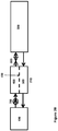
- FIG 1 is a general schematic of the process whereby wastewater from fertilizer plant 100 is first concentrated in concentrator 200. Chloride from the wastewater is then removed in electrochemical treatment unit 300 before the wastewater is recirculated to fertilizer plant 100.
- the concentrator 200 is a forward osmosis module 210.
- the forward osmosis module 210 comprises a first compartment 400 and a second compartment 500, separated by a membrane 450. Because the stream in compartment 500 is similar in composition and concentration to stream 400, no pressure driving force, and therefore less energy, is required for removal of water from stream 400 for the forward osmosis process as compared to the reverse osmosis process.
- the forward osmosis module may be an Aquaporin INSIDETM osmosis module.
- the concentrating step described herein will not specifically concentrate the chloride ions in the wastewater but all ions present in the wastewater. This concentration step is not to be interpreted as a sole chloride purification step. Moreover, the concentration of other ions present in the wastewater may have no material effect on the efficacy of the chloride removal in the electrochemical treatment unit 300.
- the wastewater is concentrated by directing the wastewater to the first compartment 400 of the forward osmosis module 210 and the electrolyzed water is directed to the second compartment 500 of the forward osmosis module 210.
- the wastewater is then recirculated from the second compartment 500 of the forward osmosis module 210 to the fertilizer plant 100.
- the flow of the wastewater in the first compartment 400 is counter-current with respect to the flow in the second compartment 500.
- the concentration gradients in each compartment will be more favorable in performing the concentration step when such counter-current flow profile is operated.
- forward osmosis can also be used with co-current flow.
- chloride can be concentrated from approximately 1000 ppm 2500 ppm or considered alternately by a factor of 2.5 times. This should not be considered a theoretical limit on the amount of concentration which can be performed. This will depend upon the solution to be concentrated, the mode of contacting, concurrent or countercurrent, the specifics of the contacting equipment, and the tendency of the solution to foul the osmosis membranes by precipitation. In general, the process will benefit by concentrating a solution as much as possible until a practical limit such as solubility is reached.
- fertilizer plant 100 is a fertilizer plant producing compositions comprising ammonium nitrate. Chloride removal will be necessary when such compositions are produced, in order to ensure recycling of safe and acceptably low levels of chlorine to fertilizer plant 100.
- concentration of chloride in the electrolyzed water recycled to the fertilizer plant 100 through the second compartment 500 is less than 350 ppm.
- the concentration step is further improved upon adding a salt solution to the second compartment 500 of the osmosis module 210 from salt reservoir 600, as shown in Figure 2A .
- a salt solution to the second compartment 500 will increase the osmotic pressure and will, thereby further drive the flow of water molecules from the first compartment 400 to the second compartment 500.
- any salt solution may be used for increasing the osmosis pressure.
- an increased osmotic pressure will reduce the size of the concentration step.
- the salt solution from salt reservoir 600 is a fertilizer solution essentially free of chloride.
- essentially free of chloride means less than 500 ppm, more particularly lower than 350 ppm and even more particularly even lower levels, such as below 250 ppm, below 200 ppm, or below 150 ppm. Those low levels of chloride ions will prevent any safety hazard in the downstream fertilizer process.
- the fertilizer plant 100 to which the electrolyzed water is recycled is an ammonium nitrate plant and the salt solution from salt reservoir 600 is an ammonium nitrate salt solution.
- the fertilizer plant 100 to which the electrolyzed water is recycled is a nitro-phosphate or other organo-mineral fertilizer plant and the salt solution from salt reservoir 600 s a fertilizer solution comprises mainly ammonium nitrate, ammonium calcium phosphates or calcium nitrate or a combination thereof. In this manner, part of an existing feed of the process can be utilized as the feed of saturated solution to the second compartment 500 of the osmosis module 210.
- any salt solution could be used to increase the osmotic pressure across membrane 450.
- the only real restriction on the selection of an appropriate salt solution is that any salt should be essentially free of chloride.
- essentially free means that there is less chloride present in the salt solution as would be present in the wastewater after the electrolysis step.
- the salt solution should not be providing additional chloride back to the wastewater.
- the salt solution from salt reservoir 600 contains less than 500 ppm, more particularly less than 350 ppm, less than 250 ppm, less than 200 ppm or even less than 150 ppm of chloride.
- the forward osmosis module shown in Figure 2A is replaced by a pressure assisted osmosis module.
- This requires a pump 700 and a back pressure valve 800 but substantially reduces the pressure required for osmosis by using the product stream as a draw in compartment 500. It also permits the processing of more concentrated streams than could generally be processed by reverse osmosis by reducing the pressure required to drive fluid across the membrane.
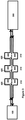
- the concentrating unit 200 can include multiple forward osmosis modules 210 connected in series, for example, 2 or 3 forward osmosis modules.
- Figure 3 is an illustration of such an embodiment containing 3 forward osmosis modules 210 connected in series and each comprising a first compartment 400 and a second compartment 500 separated by a membrane 450.
- the wastewater is subsequently treated through the electrochemical treatment unit 300.
- the flow of the wastewater in the first compartments 400 can be counter-current with the flow in the second compartments 450 as shown in Figure 3 or the flow can be co-current.
- a divided electrochemical cell was equipped with an anode which was a dimensionally stable anode from Permascand, and the cathode was SS 316 stainless steel.
- the membrane separator was Nafion 324.
- a chloride selective electrode was used on the anolyte samples to measure chloride concentration over the duration of the experiment.
- the construction material of the cell was PVC.
- Wastewater from Porsgrunn comprising 1100 ppm chloride with a weight percentage of dissolved solids of 5.1 % comprising primarily of ammonium nitrate, was added to the anode chamber of an electrochemical cell and the pH was adjusted down to 2.0 with nitric acid.
- a catholyte solution of sodium sulphate was prepared and pH adjusted down to 0.5 with nitric acid such that it had the same ionic strength as the wastewater to minimize osmotic water transfer in the cell. This solution was then added to the cathode compartment of the cell.
- the cell was operated with a current density of 860 A m -2 in a batch-wise mode. The experiment was performed at room temperature. Calculations showed that the Faradaic current efficiency was approximately 8 % for chloride removal down to 200 ppm over 115 minutes.
- Example 2 without feed of calcium nitrate for forward osmosis draw
- a divided electrochemical cell was equipped with an anode which was a dimensional stable anode from Permascand, and the cathode was SS 316 stainless steel.
- the membrane separator was Nafion 324.
- a chloride selective electrode was used on the anolyte samples to measure chloride concentration over the duration of the experiment.
- the construction material of the cell was PVC.
- the wastewater stream according to example 1 was first directed at a flow rate of 1.1 L/min to the tube-side inlet of an Aquaporin Module comprising a tube and shell compartment where the tubes are made of a water-permeable membrane.
- This Aquaporin INSIDETM module was a tube-in-shell forward osmosis unit with a 2.3 m 2 membrane area.
- the chloride concentration of the wastewater exiting the tube-side was 1470 ppm and the weight percentage of the solids in this exiting solution, at the outlet of the first compartment was 7.4 %. This outlet wastewater was collected at a rate of 0.8 L/min.
- the draw stream fed to the shell of the Aquaporin module was a "simulated" strengthened solution which would be returned from the electrochemical cell after the chloride was removed.
- This "simulated" wastewater had a solids weight percentage of 14% ammonium nitrate with 0 ppm of chloride. It was fed to the shell at 0.9 L/min.
- the outlet stream from the shell had a weight percentage of solids of 10.3%, contained 26 ppm of chloride, and was collected at 1.2 L/min.
- the concentrated wastewater was added to the anode chamber of an electrochemical cell and the pH was adjusted down to 2.0 with nitric acid.
- a catholyte solution of sodium sulphate was prepared and pH adjusted down to 0.5 with nitric acid such that it had the same ionic strength as the wastewater to minimize osmotic water transfer in the cell. This solution was then added to the cathode compartment of the cell.
- the cell was operated with a current density of 860 A m -2 in a batch-wise mode. The experiment was performed at room temperature. Interpolating from experimental results, the Faradaic current efficiency was approximately 25 % for chloride removal from 1470 ppm down to 400 ppm over 120 minutes. If this solution were then diluted in a forward osmosis module as the draw stream (as in Figure 2A ) to a solids content from Example 1 of 5.1 % solids, the chloride level would be below 200 ppm, equivalent to the result from Example 1 in which no concentration step was performed prior to the electrolysis step.
- This experiment represented a potential single stage in a counter-current cascade forward osmosis system that would bring the typical wastewater from 1100 to 2000 ppm of chloride to operate the electrochemical cell at a higher Faradaic current efficiency.
- the stream could be re-used as a draw stream for the FO system, because it will be slightly concentrated due to evaporation and water loss from electrolysis.
- a divided electrochemical cell was equipped with an anode which was a dimensionally stable anode from Permascand, and the cathode was SS 316 stainless steel.
- the membrane separator was Nafion 324.
- a chloride selective electrode was used on the anolyte samples to measure chloride concentration over the duration of the experiment.
- the construction material of the cell was PVC.
- wastewater at 25 °C from Porsgrunn comprising 1100 ppm chloride with a weight percentage of solids of 5.1 % was directed at a flow rate of 1.1 L/min to the tube-side inlet of an Aquaporin Module comprising a tube and shell compartment where the tubes are made of a water-permeable membrane.
- This Aquaporin INSIDETM module was a tube-in-shell forward osmosis unit with a 2.3 m 2 membrane area.
- the chloride concentration of the wastewater exiting the tube-side was 1470 ppm and the weight percentage of the solids in this exiting solution, at the outlet of the first compartment was 7.4 %.
- This outlet wastewater was collected at a rate of 0.8 L/min.
- the draw stream fed to the shell of the Aquaporin module was a "simulated" strengthened solution which would be returned from the electrochemical cell after the chloride was removed.
- This "simulated" wastewater had a solids weight percentage of 14% ammonium nitrate with 0 ppm of chloride. It was fed to the shell at 0.9 L/min.
- the outlet stream from the shell had a weight percentage of solids of 10.3%, contained 26 ppm of chloride, and was collected at 1.2 L/min.
- the concentrated wastewater was added to the anode chamber of an electrochemical cell and the pH was adjusted down to 2.0 with nitric acid.
- a catholyte solution of sodium sulphate was prepared and pH adjusted down to 0.5 with nitric acid such that it had the same ionic strength as the wastewater to minimize osmotic water transfer in the cell. This solution was then added to the cathode compartment of the cell.
- the cell was operated with a current density of 860 A m -2 in a batch-wise mode. The experiment was performed at room temperature. Calculations showed that the Faradaic current efficiency was approximately 25 % for chloride removal down to 400 ppm over 120 minutes; If this solution were then diluted in a forward osmosis module as the draw stream (as in Figure 2A ) to a solids content from Example 1 of 5.1 % solids, the chloride level would be below 200 ppm, equivalent to the result from Example 1 in which no concentration step was performed prior to the electrolysis step.
- This experiment represented a potential single stage in a counter-current cascade forward osmosis system that would bring the typical wastewater from 1100 to 2000 ppm of chloride to operate the electrochemical cell at a higher Faradaic current efficiency.
- the stream could be dosed with calcium nitrate - a salt used downstream in a typical nitrophosphate fertilizer process - before being used as a draw stream for the forward osmosis system.
- This stream would now have a significantly higher ionic strength compared to the feed stream and would reduce the membrane area required for the forward osmosis system.
- US 8,703,077 B2 describes a process for extraction of uranium from phosphoric acid.
- the process uses iron exchange or solvent extraction to remove the uranium from a phosphoric acid stream which is then returned to process.
- Iron in the ferric state which is present in the acid together with the uranium, competes with the uranium for sites on the ion exchange resin or in the solvent extraction.
- Electroreduction of ferric iron to ferrous iron which does not compete with uranium in the Ion exchange/solvent extraction process, is presented as one option to improve the performance of the uranium extraction process.
- the Faradaic current efficiency of this electroreduction process will be limited by competition of reduction of ferric to ferrous with evolution of hydrogen due to the low concentration of iron in the acidic solution.
- Osmotic concentration of the solution feeding the cell either by forward or assisted osmosis, using the treated stream as a draw, will benefit the process by raising the concentration of ferric iron in the feed, and raising the Faradaic current efficiency
- the oil and gas sector is facing increasing pressure to properly handle "produced water".
- This is a saline stream which is extracted together with the hydrocarbon. It contains primarily sodium chloride at a concentration which may be up to approximately 5 wt % salt. More typically the concentration is closer to seawater, approximately 3.5 wt% NaCl.
- the process of electrochemical salt splitting is made more efficient by working with the strongest available brine. Also, water addition is required in the anolyte and catholyte compartments of the electrochemical cell to maintain the concentration of these products. Forward osmosis between the products and the feed solutions, as detailed in this patent, is suited to reducing the power consumption of the overall process by economically concentrating the feed stream, while maintaining the anolyte and catholyte concentrations by dilution using the water extracted from the feed.
- Sodium sulphate can be split electrochemically in a 3 compartment cell.
- the sodium sulphate solution flows into the center compartment where sodium ions pass through a cation exchange membrane into the catholyte compartment, and sulphate ions pass through an anion exchange membrane into the anolyte. Due to the mechanism of transfer through the membranes, there is significant water transfer (roughly 12-15x mol H 2 O/mol Na 2 SO 4 ) out of the center compartment into the anolyte and catholyte compartments. To minimize voltaic losses in the center compartment, this stream would not run to full depletion but be recycled back to the solid dissolution stage of the process. Additional water would be required to make up for the lost water across the membranes.
- the sulfuric acid concentration in the anolyte compartment cannot be economically operated above approximately 2.0 mol/L without losses in the Faradaic current efficiency due to back-migration through the membrane.
- the acid stream would subsequently be concentrated in various stages up to, for example, 98 wt%. Since the center compartment (with the sodium sulphate) can be operated close to the solubility limit (roughly 2.6 mol/L), there is an ionic gradient between the two streams that could be utilized in a forward osmosis system to remove water from the product acid stream and added to the recycle sodium sulphate stream for the dissolution of fresh solid sodium sulphate. This approach would be an energy efficient process for the initial concentration of the product sulphuric acid and could additionally increase the Faradaic current efficiency by operating at a lower acid concentration in the anolyte compartment.
Landscapes
- Chemical & Material Sciences (AREA)
- Organic Chemistry (AREA)
- Engineering & Computer Science (AREA)
- Environmental & Geological Engineering (AREA)
- Water Supply & Treatment (AREA)
- Hydrology & Water Resources (AREA)
- Life Sciences & Earth Sciences (AREA)
- Chemical Kinetics & Catalysis (AREA)
- Electrochemistry (AREA)
- General Chemical & Material Sciences (AREA)
- Water Treatment By Electricity Or Magnetism (AREA)
- Fertilizers (AREA)
- Separation Using Semi-Permeable Membranes (AREA)
Priority Applications (11)
| Application Number | Priority Date | Filing Date | Title |
|---|---|---|---|
| EP18194743.3A EP3623347A1 (fr) | 2018-09-17 | 2018-09-17 | Procédé d'élimination d'un contaminant à partir d'eaux usées provenant d'une installation industrielle et système permettant de mettre en uvre un tel procédé |
| BR112021005056-6A BR112021005056B1 (pt) | 2018-09-17 | 2019-09-17 | Método para remoção de um contaminante de águas residuais de uma usina industrial e um sistema para realizar o referido método |
| LTEPPCT/EP2019/074768T LT3853179T (lt) | 2018-09-17 | 2019-09-17 | Būdas teršalui pašalinti iš pramonės gamyklos nuotekų ir tokio būdo atlikimo sistema |
| PCT/EP2019/074768 WO2020058218A1 (fr) | 2018-09-17 | 2019-09-17 | Procédé d'élimination d'un contaminant d'eaux usées d'une installation industrielle et système pour la mise en oeuvre d'un tel procédé |
| PL19765401.5T PL3853179T3 (pl) | 2018-09-17 | 2019-09-17 | Sposób usuwania zanieczyszczeń ze ścieków z zakładu przemysłowego oraz system do wykonywania tej metody |
| CN201980047714.9A CN112437754B (zh) | 2018-09-17 | 2019-09-17 | 用于从来自工业工厂的废水去除污染物的方法和用于实施这样的方法的系统 |
| ES19765401T ES2922325T3 (es) | 2018-09-17 | 2019-09-17 | Método para eliminar un contaminante de aguas residuales de una planta industrial y un sistema para llevar a cabo dicho método |
| US17/274,157 US11767240B2 (en) | 2018-09-17 | 2019-09-17 | Method for removing a contaminant from wastewater from an industrial plant and a system for performing such method |
| EP19765401.5A EP3853179B1 (fr) | 2018-09-17 | 2019-09-17 | Procédé d'élimination d'un contaminant à partir d'eaux usées provenant d'une installation industrielle et système permettant de mettre en uvre un tel procédé |
| CONC2021/0003292A CO2021003292A2 (es) | 2018-09-17 | 2021-03-12 | Metodo para remover un contaminante de aguas residuales de una planta industrial y un sistema para realizar dicho metodo |
| US18/231,531 US20230391641A1 (en) | 2018-09-17 | 2023-08-08 | Method for removing a contaminant from wastewater from an industrial plant and a system for performing such method |
Applications Claiming Priority (1)
| Application Number | Priority Date | Filing Date | Title |
|---|---|---|---|
| EP18194743.3A EP3623347A1 (fr) | 2018-09-17 | 2018-09-17 | Procédé d'élimination d'un contaminant à partir d'eaux usées provenant d'une installation industrielle et système permettant de mettre en uvre un tel procédé |
Publications (1)
| Publication Number | Publication Date |
|---|---|
| EP3623347A1 true EP3623347A1 (fr) | 2020-03-18 |
Family
ID=63762193
Family Applications (2)
| Application Number | Title | Priority Date | Filing Date |
|---|---|---|---|
| EP18194743.3A Withdrawn EP3623347A1 (fr) | 2018-09-17 | 2018-09-17 | Procédé d'élimination d'un contaminant à partir d'eaux usées provenant d'une installation industrielle et système permettant de mettre en uvre un tel procédé |
| EP19765401.5A Active EP3853179B1 (fr) | 2018-09-17 | 2019-09-17 | Procédé d'élimination d'un contaminant à partir d'eaux usées provenant d'une installation industrielle et système permettant de mettre en uvre un tel procédé |
Family Applications After (1)
| Application Number | Title | Priority Date | Filing Date |
|---|---|---|---|
| EP19765401.5A Active EP3853179B1 (fr) | 2018-09-17 | 2019-09-17 | Procédé d'élimination d'un contaminant à partir d'eaux usées provenant d'une installation industrielle et système permettant de mettre en uvre un tel procédé |
Country Status (8)
| Country | Link |
|---|---|
| US (2) | US11767240B2 (fr) |
| EP (2) | EP3623347A1 (fr) |
| CN (1) | CN112437754B (fr) |
| CO (1) | CO2021003292A2 (fr) |
| ES (1) | ES2922325T3 (fr) |
| LT (1) | LT3853179T (fr) |
| PL (1) | PL3853179T3 (fr) |
| WO (1) | WO2020058218A1 (fr) |
Families Citing this family (3)
| Publication number | Priority date | Publication date | Assignee | Title |
|---|---|---|---|---|
| EP4096738A1 (fr) * | 2020-01-28 | 2022-12-07 | Fresenius Medical Care Deutschland GmbH | Dispositif et procédé de production de dialysat |
| IL298376A (en) * | 2020-05-20 | 2023-01-01 | Harvard College | Forward osmosis driven by electrolysis |
| CN116040869B (zh) * | 2023-01-09 | 2025-05-16 | 江苏南大华兴环保科技股份公司 | 一种高效脱除低盐废水中氨氮的处理系统及工艺 |
Citations (7)
| Publication number | Priority date | Publication date | Assignee | Title |
|---|---|---|---|---|
| JP2000051817A (ja) * | 1998-08-07 | 2000-02-22 | Ube Ind Ltd | 塩化ビニール樹脂を含む有機性廃棄物のリサイクル法 |
| US6132627A (en) | 1996-12-18 | 2000-10-17 | Kurita Water Industries Ltd. | Treatment method for water containing nitrogen compounds |
| US8703077B2 (en) | 2008-07-31 | 2014-04-22 | Urtek, Llc. | Extraction of uranium from wet-process phosphoric acid |
| CN204138483U (zh) * | 2014-10-10 | 2015-02-04 | 南京舜业环保科技有限公司 | 酸洗镍废水回收循环再生装置 |
| WO2015058109A1 (fr) * | 2013-10-18 | 2015-04-23 | Dow Global Technologies Llc | Processus d'extraction de saumure |
| WO2017103041A1 (fr) | 2015-12-18 | 2017-06-22 | Yara International Asa | Procédés d'élimination du chlorure présent dans des eaux résiduaires d'engrais |
| WO2017103042A1 (fr) | 2015-12-18 | 2017-06-22 | Yara International Asa | Procédés de traitement des eaux résiduaires industrielles par électrolyse |
Family Cites Families (8)
| Publication number | Priority date | Publication date | Assignee | Title |
|---|---|---|---|---|
| US3422425A (en) | 1965-06-29 | 1969-01-14 | Rca Corp | Conversion from nrz code to selfclocking code |
| US6315886B1 (en) | 1998-12-07 | 2001-11-13 | The Electrosynthesis Company, Inc. | Electrolytic apparatus and methods for purification of aqueous solutions |
| FI117618B (fi) | 2004-02-10 | 2006-12-29 | Kemira Oyj | Menetelmä ammoniumin poistamiseksi jätevedestä |
| PL3307423T3 (pl) | 2015-06-12 | 2021-09-13 | Spraying Systems Co. | System elektrolizowania wody o dużej objętości i sposób jego wykorzystywania |
| US20170129796A1 (en) * | 2015-11-10 | 2017-05-11 | Nrgtek, Inc. | Hybrid Systems and Methods with Forward Osmosis and Electrodeionization Using High-Conductivity Membranes |
| CN105417801A (zh) * | 2016-01-18 | 2016-03-23 | 青岛理工大学 | 一种正渗透与电渗析协同从污水中提取淡水的方法及系统 |
| EP3497266B1 (fr) | 2016-08-10 | 2021-07-21 | Covestro Intellectual Property GmbH & Co. KG | Procede de nettoyage electrochimique de solutions de processus contenant du chlorure |
| US10848894B2 (en) | 2018-04-09 | 2020-11-24 | Nokia Technologies Oy | Controlling audio in multi-viewpoint omnidirectional content |
-
2018
- 2018-09-17 EP EP18194743.3A patent/EP3623347A1/fr not_active Withdrawn
-
2019
- 2019-09-17 EP EP19765401.5A patent/EP3853179B1/fr active Active
- 2019-09-17 LT LTEPPCT/EP2019/074768T patent/LT3853179T/lt unknown
- 2019-09-17 WO PCT/EP2019/074768 patent/WO2020058218A1/fr not_active Ceased
- 2019-09-17 CN CN201980047714.9A patent/CN112437754B/zh active Active
- 2019-09-17 PL PL19765401.5T patent/PL3853179T3/pl unknown
- 2019-09-17 ES ES19765401T patent/ES2922325T3/es active Active
- 2019-09-17 US US17/274,157 patent/US11767240B2/en active Active
-
2021
- 2021-03-12 CO CONC2021/0003292A patent/CO2021003292A2/es unknown
-
2023
- 2023-08-08 US US18/231,531 patent/US20230391641A1/en active Pending
Patent Citations (7)
| Publication number | Priority date | Publication date | Assignee | Title |
|---|---|---|---|---|
| US6132627A (en) | 1996-12-18 | 2000-10-17 | Kurita Water Industries Ltd. | Treatment method for water containing nitrogen compounds |
| JP2000051817A (ja) * | 1998-08-07 | 2000-02-22 | Ube Ind Ltd | 塩化ビニール樹脂を含む有機性廃棄物のリサイクル法 |
| US8703077B2 (en) | 2008-07-31 | 2014-04-22 | Urtek, Llc. | Extraction of uranium from wet-process phosphoric acid |
| WO2015058109A1 (fr) * | 2013-10-18 | 2015-04-23 | Dow Global Technologies Llc | Processus d'extraction de saumure |
| CN204138483U (zh) * | 2014-10-10 | 2015-02-04 | 南京舜业环保科技有限公司 | 酸洗镍废水回收循环再生装置 |
| WO2017103041A1 (fr) | 2015-12-18 | 2017-06-22 | Yara International Asa | Procédés d'élimination du chlorure présent dans des eaux résiduaires d'engrais |
| WO2017103042A1 (fr) | 2015-12-18 | 2017-06-22 | Yara International Asa | Procédés de traitement des eaux résiduaires industrielles par électrolyse |
Non-Patent Citations (1)
| Title |
|---|
| SHIQIANG ZOU ET AL: "Electrodialysis recovery of reverse-fluxed fertilizer draw solute during forward osmosis water treatment", CHEMICAL ENGINEERING JOURNAL, vol. 330, 31 July 2017 (2017-07-31), pages 550 - 558, XP055526524, ISSN: 1385-8947, DOI: 10.1016/j.cej.2017.07.181 * |
Also Published As
| Publication number | Publication date |
|---|---|
| EP3853179B1 (fr) | 2022-06-22 |
| WO2020058218A1 (fr) | 2020-03-26 |
| US20230391641A1 (en) | 2023-12-07 |
| PL3853179T3 (pl) | 2022-08-22 |
| US20210276889A1 (en) | 2021-09-09 |
| CN112437754B (zh) | 2022-11-11 |
| US11767240B2 (en) | 2023-09-26 |
| LT3853179T (lt) | 2022-07-25 |
| CO2021003292A2 (es) | 2021-03-29 |
| ES2922325T3 (es) | 2022-09-13 |
| CN112437754A (zh) | 2021-03-02 |
| EP3853179A1 (fr) | 2021-07-28 |
| BR112021005056A2 (pt) | 2021-06-08 |
Similar Documents
| Publication | Publication Date | Title |
|---|---|---|
| US20230391641A1 (en) | Method for removing a contaminant from wastewater from an industrial plant and a system for performing such method | |
| AU2024220043B2 (en) | Li recovery processes and onsite chemical production for li recovery processes | |
| EP2867388B1 (fr) | Procédé et appareil de génération ou de récupération d'acide chlorhydrique à partir de solutions de sels métalliques | |
| CN104379512B (zh) | 氨处理系统 | |
| US20170014758A1 (en) | Conversion of gas and treatment of a solution | |
| EP3390285B1 (fr) | Procédés de traitement des eaux résiduaires industrielles par électrolyse | |
| EP3895785A1 (fr) | Unité de dessalement et de séquestration de gaz à effet de serre | |
| CN120019175A (zh) | 从电池制造和回收出口料流中电化学生产碱金属氢氧化物和硫酸 | |
| EP3390284B1 (fr) | Procédé et système d'élimination du chlorure présent dans des eaux résiduaires d'engrais | |
| CN113200633A (zh) | 一种利用垃圾渗滤液制氢的方法及系统 | |
| EP0967003B1 (fr) | Procédé et système pour le traitement des gaz d'échappement | |
| RU2793787C2 (ru) | Способ удаления загрязняющих веществ из сточной воды от промышленного производства и система для осуществления такого способа | |
| BR112021005056B1 (pt) | Método para remoção de um contaminante de águas residuais de uma usina industrial e um sistema para realizar o referido método | |
| HK1210233B (en) | Process and apparatus for generating or recovering hydrochloric acid from metal salt solutions |
Legal Events
| Date | Code | Title | Description |
|---|---|---|---|
| PUAI | Public reference made under article 153(3) epc to a published international application that has entered the european phase |
Free format text: ORIGINAL CODE: 0009012 |
|
| AK | Designated contracting states |
Kind code of ref document: A1 Designated state(s): AL AT BE BG CH CY CZ DE DK EE ES FI FR GB GR HR HU IE IS IT LI LT LU LV MC MK MT NL NO PL PT RO RS SE SI SK SM TR |
|
| AX | Request for extension of the european patent |
Extension state: BA ME |
|
| STAA | Information on the status of an ep patent application or granted ep patent |
Free format text: STATUS: THE APPLICATION IS DEEMED TO BE WITHDRAWN |
|
| 18D | Application deemed to be withdrawn |
Effective date: 20200919 |