EP3627164A1 - Steuervorrichtung eines trennorgans einer elektrischen anlage, und testverfahren dieser vorrichtung - Google Patents
Steuervorrichtung eines trennorgans einer elektrischen anlage, und testverfahren dieser vorrichtung Download PDFInfo
- Publication number
- EP3627164A1 EP3627164A1 EP19195694.5A EP19195694A EP3627164A1 EP 3627164 A1 EP3627164 A1 EP 3627164A1 EP 19195694 A EP19195694 A EP 19195694A EP 3627164 A1 EP3627164 A1 EP 3627164A1
- Authority
- EP
- European Patent Office
- Prior art keywords
- power transistor
- control
- circuit
- voltage
- transistor
- Prior art date
- Legal status (The legal status is an assumption and is not a legal conclusion. Google has not performed a legal analysis and makes no representation as to the accuracy of the status listed.)
- Granted
Links
Images

Classifications
-
- G—PHYSICS
- G01—MEASURING; TESTING
- G01R—MEASURING ELECTRIC VARIABLES; MEASURING MAGNETIC VARIABLES
- G01R31/00—Arrangements for testing electric properties; Arrangements for locating electric faults; Arrangements for electrical testing characterised by what is being tested not provided for elsewhere
- G01R31/327—Testing of circuit interrupters, switches or circuit-breakers
- G01R31/3271—Testing of circuit interrupters, switches or circuit-breakers of high voltage or medium voltage devices
- G01R31/3275—Fault detection or status indication
Definitions
- the field of the invention is that of electrical installations, and more particularly the control of the safety members of an electrical installation.
- the invention relates to a device for controlling a cut-off member of an electrical installation, and in particular of an ultra-fast circuit breaker.
- the invention finds its application in particular in the field of power supply to rail networks, in particular for tram, RER ("regional express network”) and metro networks.
- circuit breakers over fuses are inexpensive and have the advantages of being reset, that is, they can be reused because they are not expected to be damaged during operation.
- the network security elements typically include ultra-fast (or DUR) circuit breakers, that is, say having a fast opening speed.
- NF EN 50126, NF EN 50 128, NF EN 50129 and IEC 61508 are applicable to all players in the rail sector and define safety levels allowing products to be produced that meet safety expectations.
- an ultra fast circuit breaker is equipped with a control coil to open or close the circuit breaker, and is controlled by a protection relay.
- a solenoid coil of an ultra-fast circuit breaker demagnetizes, conventionally, in approximately 6 milliseconds (or ms). However, it takes about 5 milliseconds for a protection relay to switch, or about 10 milliseconds for the relay to open and close. Thus, by the time the relay is opened and then closed, the solenoid coil of the high-speed circuit breaker discharges and the electrical network is cut by the tripping of the circuit breaker by the coil.
- the invention particularly aims to overcome these drawbacks of the prior art.
- an objective of the invention is to provide a circuit for controlling a circuit breaker which is reliable.
- Another objective of the invention is to provide a technique making it possible to ensure the proper functioning of such a control circuit without affecting or interrupting the operation of the electrical installation.
- the invention also aims to provide such a technique which is relatively inexpensive to implement and which meets the requirements of the railway and the standards in force.
- a device for controlling a cut-off member of an electrical installation such as an ultra-fast circuit breaker, comprising a control relay, the input terminal of which is connected to electrical supply means and the output terminal of which is connected to a power transistor, the output terminal of the power transistor being connected to said switching device, the device comprising further means for continuously monitoring the operating state of said power transistor, said continuous monitoring means comprising a control circuit for the power transistor capable of generating a predetermined electrical pulse intended to switch said power transistor, a malfunction of said power transistor being detected when the latter does not switch in response to said predetermined electrical pulse.
- the invention therefore provides a device for testing the control circuit of a circuit breaker of an electrical installation, without interrupting the operation thereof.
- This function continuously monitors the control circuit to ensure that it is capable of tripping the breaking device without interrupting the operation of the installation in which the circuit breaker and its control circuit are operated.
- the protection relay is associated on the side of its output with a transistor which is controlled by switching. If it is detected that the transistor is not switching, a anomaly is identified and the circuit breaker is no longer supplied with power until the anomaly is resolved.
- said continuous control means further comprise a circuit for measuring the voltage at the terminals of said power transistor, said circuit for measuring the voltage at the terminals of said power transistor comprising a first portion of circuit located upstream from said power transistor and a second circuit portion located downstream of said power transistor.
- said predetermined electrical pulse is a voltage blackout of duration between 0.1 ms and 1 ms.
- said electrical pulse is applied periodically, the period being substantially equal to one tenth of a millisecond.
- said power transistor (2) has a switching time of 100 ns.
- the device further comprises a control circuit for said piloting relay.
- said output terminal of said power transistor is an "all or nothing" output.
- said power transistor and said control relay are binary controlled in opposite directions.
- the electrical supply means supply the electrical installation with a direct current.
- said step of generating a predetermined electrical pulse being of duration between 0.1 ms and 1 ms.
- test method is repeated periodically, the period being substantially equal to one tenth of a millisecond.
- the test method further comprises a step of checking the operating state of said control relay.
- the method comprises a step of cutting the voltage at said output terminal of said power transistor.
- Ultra-fast circuit breakers when used in the railway sector, make it possible to protect and isolate the section, or sub-station, of the overhead contact line (supply line above the rolling stock, by example for a tram), or the ground contact line (supply line under rolling stock, for example for a metro) against faults and possible overloads. They can, for example, be secured by mechanical locking, in order to allow any maintenance action on the electrical section in complete safety. Finally, they are able to communicate with the circuit breakers of the adjacent substations.
- the ultra-fast circuit breaker includes an internal breaking circuit comprising an electromagnetic control coil.
- This coil has a demagnetization time of several milliseconds, generally of the order of 5 to 10 milliseconds. In this way, the ultra fast circuit breaker is protected against micro-breaks which could take place within the electrical circuit in which it is placed, and will not trip at each micro-break less than the demagnetization time of the coil.
- the invention provides a device for controlling a new structure.
- the control or piloting device 1 of a cut-off member of an electrical installation which is in this embodiment an ultra-fast circuit breaker 4, comprises a power relay, called a pilot relay, 3 constituting a switch and comprising a coil controlling a contact.
- the input terminal of the control relay 3 is connected to power supply means 5 and its output terminal is connected to a power transistor 2 forming a switch, the output terminal of the power transistor 2, called fast output , being connected to the high-speed circuit breaker 4.
- control relay 3 and the power transistor 2 are connected in series in the supply circuit of the control coil of the ultra-fast circuit breaker 4, the control coil being intended to close or open the circuit breaker when it is powered or not, respectively.
- this input terminal of the control relay can for example comprise an angled capacitor
- the electrical supply means supply a direct current.
- the current flowing in the high-speed circuit breaker can vary from 0 A to 8 kA nominal and can tolerate faults up to 100 kA.
- control device can also comprise at least one protection diode, for example a first diode 8 in series with a Zener diode 9.
- control relay 3 and of the power transistor 2 makes it possible to obtain a double level of dependability, without common mode, so as to be able, for example in the event of detection of an anomaly on the electrical circuit , allow tripping of the breaking device, namely the ultra-fast circuit breaker 4.
- the power transistor 2 is, in this embodiment, an n-type MOSFET transistor (having a gate, a drain and a source). It will be recalled that when the gate-source voltage V GS is less than the threshold voltage, it is said that the transistor is blocked, it does not conduct. Otherwise, it is said to be conducting, and in this case, it conducts the current between the drain and the source. Thus the power transistor 2 can switch according to the voltage applied between the gate and the source.
- the control relay 3 To respond to the failure modes (blocked open or blocked closed) of the power transistor 2, the control relay 3 is arranged in series (for the blocked blocked mode) and in the blocked open mode, the danger for people is zero because the ultra fast circuit breaker 4 is blocked open.
- the invention proposes to verify during operation that the power transistor 2 and the control relay 3 have the capacity to switch.
- control or piloting device 1 comprises means for continuously monitoring the operating state of the power transistor 2, said means for continuously monitoring comprising a control circuit 21 capable of generating a predetermined electrical pulse intended to switch said power transistor 2.
- control circuit 21 of the power transistor 2 comprises a voltage converter, 211 and an operational amplifier 212 which is mounted in a follower arrangement.
- the control circuit 21 is configured to inject a test signal on the gate of the power transistor 2.
- the voltage converter 211 is more particularly programmed to establish a predetermined test sequence so as to determine the operation or non-operation of the power transistor 2 continuously. This allows the operating state of the circuit breaker control circuit to be tested at any time.
- the test is carried out by means of a program executed by the voltage converter 211. This test can be triggered periodically.
- a malfunction of the power transistor 2 (which corresponds to the blocking of the transistor in open or closed position) can be detected when the latter does not switch in response to a predetermined electrical pulse sent by the control circuit 2.
- This pulse electrical corresponds to a voltage micro-interruption of duration between 0.1ms and 1ms.
- the power transistor 2 has a switching time of 100 ns.
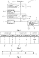
- the test signal illustrated in figure 4 includes a periodic electrical pulse, the period being between X and Y seconds.
- this period is of the order of a tenth of a millisecond.
- the continuous control means further comprise a circuit for measuring the voltage across the terminals of the power transistor 2.
- the voltage converter 211 thus detects the voltage at the terminals of the power transistor 2 by means of a voltage measurement circuit which is mounted in bypass. across the power transistor 2 to detect a conduction or non-conduction state thereof for the purpose of carrying out a test of its correct operation.
- This circuit for measuring the voltage across the power transistor 2 comprises a first portion 6 of circuit placed upstream of the power transistor 4 and a second portion 7 of circuit placed downstream of the power transistor 4.
- each of these two portions 6, 7 of the voltage measurement circuit across the power transistor is provided with a plurality of modules, each of these modules comprising a transistor connected to a resistor.
- the power transistor 2 is encouraged to switch. If the voltage value across the power transistor 2 does not change then it is determined that the latter is blocked in the open or closed position. Otherwise, if the voltage value at the terminals of the power transistor 2 changes, it is determined that the latter is in good working condition, and is capable of fulfilling its role of cutting off the installation if necessary.
- this control device 1 implements a test method, also subject of the invention.
- the step of generating a predetermined electrical pulse is implemented, according to the embodiments, for a duration of between 0.1 ms and 1 ms.
- test method is repeated periodically, the period being of the order of tenths of a millisecond.
- the voltage upstream and downstream of the power transistor 2 is measured and is then compared as a function of the state of said power transistor 2, so as to control the proper functioning of the power transistor. power 2.
- this output terminal 22 of the power transistor 2 is an “all or nothing” output, which therefore allows either all of the current or no current to pass, depending on the switching state of the transistor.
- a protection circuit 23 is implemented near this output terminal 22.
- Such a protection circuit comprises, in this embodiment, a plurality of “freewheeling” diodes and an n-type MOSFET.
- the power transistor 2 and the control relay 3 are binary opposite.
- the control relay 3 is active (closed) with a command at 0 and inactive (open) with a command at 1 while the power transistor is active (closed) with a command at 1 and inactive ( open) with a command at 0.
- the first portion 6 of the measurement circuit detects a voltage upstream of the transistor power 2 while no voltage is detected downstream of the power transistor 2 by the second portion 7 of the measurement circuit.
- the output terminal 22 of the power transistor 2 has a zero current.
- the first 6 and second 7 portions of the circuit detect a voltage.
- the output terminal 22 of the power transistor 2 has a positive current.
- the first 6 and second 7 portions of the circuit detect no voltage.
- the output terminal 22 has a zero current.
- the first portion 6 of the measurement circuit detects no voltage upstream of the power transistor 2 while no voltage is detected downstream of the power transistor 2 by the second portion 7 of the measurement circuit.
- the output terminal 22 of the power transistor 2 has a zero current.
- this “watchdog” can also be triggered if no voltage is detected upstream and downstream.
- This cutting step can, depending on the embodiment presented, appear after a predetermined number of iterations.
- the test process before opening the high-speed circuit breaker, the test process can be iterated one or more times, so as to ensure that the anomaly is real, in order to prevent the the high-speed circuit breaker is not opened by the transmission of a non-existent anomaly.
- This plurality of iterations thus makes it possible to ensure the veracity of this anomaly with enhanced reliability.
- the method comprises a step of cutting the voltage leaving the output terminal 22 of the power transistor 2.
- the method comprises the step of cutting the voltage leaving the output terminal 22 of the power transistor 2.
- the method can also comprise a step of checking the operating state of the control relay 3.
- Such a step of checking the operating state of the control relay 3 can for example be implemented before each restart of the electrical network, or during periodic maintenance phases (monthly, annual).
- This control step can also make it possible to determine whether or not to activate the piloting relay, by means of the relay control circuit.
- the closing condition of the control relay can include a plurality of preconditions such as the “ready” state of the control relay, the absence of a fault detected in the electrical network and in particular at the level of the transistor.
- the periodic maintenance phases may also include steps for controlling switching (opening and closing) of the control relay 3 and of the power transistor 2.
- test method for controlling a cut-off device which is the subject of the invention can be adapted for any type of ultra-fast circuit breaker.
- the ultra-fast circuit breaker is a 24 V, 48 V or even 127 V circuit breaker.
Landscapes
- Physics & Mathematics (AREA)
- General Physics & Mathematics (AREA)
- Emergency Protection Circuit Devices (AREA)
Applications Claiming Priority (2)
| Application Number | Priority Date | Filing Date | Title |
|---|---|---|---|
| FR1858440A FR3086062A1 (fr) | 2018-09-18 | 2018-09-18 | Dispositif de commande d’un organe de coupure d’une installation electrique et procede de test d'un tel dispositif |
| FR1901340A FR3086061B1 (fr) | 2018-09-18 | 2019-02-11 | Dispositif de commande d’un organe de coupure d’une installation électrique et procédé de test d'un tel dispositif |
Publications (2)
| Publication Number | Publication Date |
|---|---|
| EP3627164A1 true EP3627164A1 (de) | 2020-03-25 |
| EP3627164B1 EP3627164B1 (de) | 2023-08-09 |
Family
ID=67847661
Family Applications (1)
| Application Number | Title | Priority Date | Filing Date |
|---|---|---|---|
| EP19195694.5A Active EP3627164B1 (de) | 2018-09-18 | 2019-09-05 | System mit einer steuervorrichtung eines schnellschalters einer elektrischen anlage, und testverfahren dieses systems |
Country Status (1)
| Country | Link |
|---|---|
| EP (1) | EP3627164B1 (de) |
Citations (9)
| Publication number | Priority date | Publication date | Assignee | Title |
|---|---|---|---|---|
| FR2489038A1 (fr) * | 1980-08-21 | 1982-02-26 | Biegelmeier Gottfried | Disjoncteur a courant de defaut |
| FR2500927A1 (fr) * | 1981-02-27 | 1982-09-03 | Marchal Equip Auto | Disposilif de mesure du debit d'un fluide |
| FR2556904A1 (fr) * | 1983-12-20 | 1985-06-21 | Ates Componenti Elettron | Circuit de commande en commutation de charges inductives, integrale monolithiquement, comprenant un etage final de type darlington |
| FR2651915A1 (fr) * | 1989-09-13 | 1991-03-15 | Merlin Gerin | Disjoncteur statique ultra-rapide a isolement galvanique. |
| US5629610A (en) * | 1994-05-06 | 1997-05-13 | Sgs-Thomson Microelectronics S.R.L. | Dual threshold current mode digital PWM controller |
| FR2843676A1 (fr) * | 2002-06-25 | 2004-02-20 | Yazaki Corp | Appareil de pilotage de lampe pour vehicule |
| US20080007883A1 (en) * | 2006-05-15 | 2008-01-10 | Infineon Technologies Ag | Vehicle on-board electric power system |
| FR3028894A1 (fr) * | 2014-11-26 | 2016-05-27 | Peugeot Citroen Automobiles Sa | Dispositif de commande d’alimentation electrique d’un solenoide de demarreur |
| US20170110870A1 (en) * | 2014-06-23 | 2017-04-20 | Robert Bosch Gmbh | Method and device for current sensing of small currents |
-
2019
- 2019-09-05 EP EP19195694.5A patent/EP3627164B1/de active Active
Patent Citations (9)
| Publication number | Priority date | Publication date | Assignee | Title |
|---|---|---|---|---|
| FR2489038A1 (fr) * | 1980-08-21 | 1982-02-26 | Biegelmeier Gottfried | Disjoncteur a courant de defaut |
| FR2500927A1 (fr) * | 1981-02-27 | 1982-09-03 | Marchal Equip Auto | Disposilif de mesure du debit d'un fluide |
| FR2556904A1 (fr) * | 1983-12-20 | 1985-06-21 | Ates Componenti Elettron | Circuit de commande en commutation de charges inductives, integrale monolithiquement, comprenant un etage final de type darlington |
| FR2651915A1 (fr) * | 1989-09-13 | 1991-03-15 | Merlin Gerin | Disjoncteur statique ultra-rapide a isolement galvanique. |
| US5629610A (en) * | 1994-05-06 | 1997-05-13 | Sgs-Thomson Microelectronics S.R.L. | Dual threshold current mode digital PWM controller |
| FR2843676A1 (fr) * | 2002-06-25 | 2004-02-20 | Yazaki Corp | Appareil de pilotage de lampe pour vehicule |
| US20080007883A1 (en) * | 2006-05-15 | 2008-01-10 | Infineon Technologies Ag | Vehicle on-board electric power system |
| US20170110870A1 (en) * | 2014-06-23 | 2017-04-20 | Robert Bosch Gmbh | Method and device for current sensing of small currents |
| FR3028894A1 (fr) * | 2014-11-26 | 2016-05-27 | Peugeot Citroen Automobiles Sa | Dispositif de commande d’alimentation electrique d’un solenoide de demarreur |
Also Published As
| Publication number | Publication date |
|---|---|
| EP3627164B1 (de) | 2023-08-09 |
Similar Documents
| Publication | Publication Date | Title |
|---|---|---|
| EP2053741B1 (de) | Selbstschützende elektrische Schaltvorrichtung | |
| EP1764891B1 (de) | Elektronische Auslösevorrichtung mit Überwachungsmittel und entsprechendes Überwachungsverfahren | |
| EP3507877B1 (de) | Verfahren zur steuerung einer anlage mit ermöglichung von gleichstromübertragung in einem netzwerk bei schutz des netzwerks vor einem kurzschluss | |
| FR2952470A1 (fr) | Disjoncteur limiteur de courant, dispositif de distribution electrique pourvu d'un tel disjoncteur limiteur et procede de limitation de courant | |
| EP3577672B1 (de) | Hochspannungsgleichstromunterbrechungsvorrichtung | |
| EP1225673B1 (de) | Elektrische Energieverteilungsvorrichtung, Anlage mit einer solchen Vorrichtung und Verfahren zum elektrischen Schutz | |
| EP3033821A1 (de) | Remote-schutz- und schaltvorrichtung für stromsysteme | |
| EP2011235A1 (de) | Sicherheitseinrichtung für einen halbleiterschalter | |
| EP4016570B1 (de) | Elektromechanische schaltvorrichtung einer elektrischen leistungsschaltung | |
| WO2020164945A1 (fr) | Systeme de commutation statique et de limitation d'un courant continu | |
| EP4199284B1 (de) | Verfahren zur erkennung eines elektrischen fehlers, zugehörige elektrische schutzsysteme | |
| EP3627164B1 (de) | System mit einer steuervorrichtung eines schnellschalters einer elektrischen anlage, und testverfahren dieses systems | |
| EP3869659B1 (de) | Energieversorgungssystem mit mehreren batterien | |
| FR3086061A1 (fr) | Dispositif de commande d’un organe de coupure d’une installation électrique et procédé de test d'un tel dispositif | |
| EP0720193A1 (de) | Elektrisches Steuergerät zum Öffnen und Schliessen eines Last- oder Leistungsschalters | |
| FR2870996A1 (fr) | Protection de circuit electrique en mode veille pour vehicule | |
| WO2016131867A1 (fr) | Systeme de protection selective d'un reseau electrique et procede de protection associe | |
| EP3297111B1 (de) | Vorrichtung und verfahren zur überwachung der aktivität der verarbeitungseinheiten in einem elektrischen auslöser | |
| FR2976414A1 (fr) | Procede de protection differentielle d'une liaison electrique de grande longueur avec courant capacitif eleve dans un reseau moyenne, haute ou tres haute tension | |
| FR3048138A1 (fr) | Coupe-circuit et systeme de protection d'un reseau electrique | |
| EP2693585B1 (de) | Schutzsystem für eine Vielzahl von elektrischen Ableitungen gegen Kurzschlüsse, und Elektroanlage, die ein solches Schutzsystem umfasst | |
| FR3133279A1 (fr) | Système et procédé de protection d’un réseau électrique | |
| EP1378925B1 (de) | Hilfseinrichtung zur Öffnungssteuerung eines Schaltgerätes | |
| EP1764892A1 (de) | Vorrichtung zur Überwachung eines Fehlerstromes am Ausgang einer Energiequelle eines Kraftfahrzeuges | |
| EP4672289A1 (de) | Vorrichtung und verfahren zur elektrischen schaltung |
Legal Events
| Date | Code | Title | Description |
|---|---|---|---|
| PUAI | Public reference made under article 153(3) epc to a published international application that has entered the european phase |
Free format text: ORIGINAL CODE: 0009012 |
|
| STAA | Information on the status of an ep patent application or granted ep patent |
Free format text: STATUS: THE APPLICATION HAS BEEN PUBLISHED |
|
| AK | Designated contracting states |
Kind code of ref document: A1 Designated state(s): AL AT BE BG CH CY CZ DE DK EE ES FI FR GB GR HR HU IE IS IT LI LT LU LV MC MK MT NL NO PL PT RO RS SE SI SK SM TR |
|
| AX | Request for extension of the european patent |
Extension state: BA ME |
|
| STAA | Information on the status of an ep patent application or granted ep patent |
Free format text: STATUS: REQUEST FOR EXAMINATION WAS MADE |
|
| 17P | Request for examination filed |
Effective date: 20200911 |
|
| RBV | Designated contracting states (corrected) |
Designated state(s): AL AT BE BG CH CY CZ DE DK EE ES FI FR GB GR HR HU IE IS IT LI LT LU LV MC MK MT NL NO PL PT RO RS SE SI SK SM TR |
|
| STAA | Information on the status of an ep patent application or granted ep patent |
Free format text: STATUS: EXAMINATION IS IN PROGRESS |
|
| 17Q | First examination report despatched |
Effective date: 20221108 |
|
| GRAP | Despatch of communication of intention to grant a patent |
Free format text: ORIGINAL CODE: EPIDOSNIGR1 |
|
| STAA | Information on the status of an ep patent application or granted ep patent |
Free format text: STATUS: GRANT OF PATENT IS INTENDED |
|
| INTG | Intention to grant announced |
Effective date: 20230331 |
|
| P01 | Opt-out of the competence of the unified patent court (upc) registered |
Effective date: 20230519 |
|
| GRAS | Grant fee paid |
Free format text: ORIGINAL CODE: EPIDOSNIGR3 |
|
| GRAA | (expected) grant |
Free format text: ORIGINAL CODE: 0009210 |
|
| STAA | Information on the status of an ep patent application or granted ep patent |
Free format text: STATUS: THE PATENT HAS BEEN GRANTED |
|
| AK | Designated contracting states |
Kind code of ref document: B1 Designated state(s): AL AT BE BG CH CY CZ DE DK EE ES FI FR GB GR HR HU IE IS IT LI LT LU LV MC MK MT NL NO PL PT RO RS SE SI SK SM TR |
|
| REG | Reference to a national code |
Ref country code: GB Ref legal event code: FG4D Free format text: NOT ENGLISH |
|
| REG | Reference to a national code |
Ref country code: CH Ref legal event code: EP |
|
| REG | Reference to a national code |
Ref country code: IE Ref legal event code: FG4D Free format text: LANGUAGE OF EP DOCUMENT: FRENCH |
|
| REG | Reference to a national code |
Ref country code: DE Ref legal event code: R096 Ref document number: 602019034430 Country of ref document: DE |
|
| REG | Reference to a national code |
Ref country code: LT Ref legal event code: MG9D |
|
| REG | Reference to a national code |
Ref country code: NL Ref legal event code: MP Effective date: 20230809 |
|
| REG | Reference to a national code |
Ref country code: AT Ref legal event code: MK05 Ref document number: 1598135 Country of ref document: AT Kind code of ref document: T Effective date: 20230809 |
|
| PG25 | Lapsed in a contracting state [announced via postgrant information from national office to epo] |
Ref country code: GR Free format text: LAPSE BECAUSE OF FAILURE TO SUBMIT A TRANSLATION OF THE DESCRIPTION OR TO PAY THE FEE WITHIN THE PRESCRIBED TIME-LIMIT Effective date: 20231110 |
|
| PG25 | Lapsed in a contracting state [announced via postgrant information from national office to epo] |
Ref country code: IS Free format text: LAPSE BECAUSE OF FAILURE TO SUBMIT A TRANSLATION OF THE DESCRIPTION OR TO PAY THE FEE WITHIN THE PRESCRIBED TIME-LIMIT Effective date: 20231209 |
|
| PG25 | Lapsed in a contracting state [announced via postgrant information from national office to epo] |
Ref country code: SE Free format text: LAPSE BECAUSE OF FAILURE TO SUBMIT A TRANSLATION OF THE DESCRIPTION OR TO PAY THE FEE WITHIN THE PRESCRIBED TIME-LIMIT Effective date: 20230809 Ref country code: RS Free format text: LAPSE BECAUSE OF FAILURE TO SUBMIT A TRANSLATION OF THE DESCRIPTION OR TO PAY THE FEE WITHIN THE PRESCRIBED TIME-LIMIT Effective date: 20230809 Ref country code: PT Free format text: LAPSE BECAUSE OF FAILURE TO SUBMIT A TRANSLATION OF THE DESCRIPTION OR TO PAY THE FEE WITHIN THE PRESCRIBED TIME-LIMIT Effective date: 20231211 Ref country code: NO Free format text: LAPSE BECAUSE OF FAILURE TO SUBMIT A TRANSLATION OF THE DESCRIPTION OR TO PAY THE FEE WITHIN THE PRESCRIBED TIME-LIMIT Effective date: 20231109 Ref country code: NL Free format text: LAPSE BECAUSE OF FAILURE TO SUBMIT A TRANSLATION OF THE DESCRIPTION OR TO PAY THE FEE WITHIN THE PRESCRIBED TIME-LIMIT Effective date: 20230809 Ref country code: LV Free format text: LAPSE BECAUSE OF FAILURE TO SUBMIT A TRANSLATION OF THE DESCRIPTION OR TO PAY THE FEE WITHIN THE PRESCRIBED TIME-LIMIT Effective date: 20230809 Ref country code: LT Free format text: LAPSE BECAUSE OF FAILURE TO SUBMIT A TRANSLATION OF THE DESCRIPTION OR TO PAY THE FEE WITHIN THE PRESCRIBED TIME-LIMIT Effective date: 20230809 Ref country code: IS Free format text: LAPSE BECAUSE OF FAILURE TO SUBMIT A TRANSLATION OF THE DESCRIPTION OR TO PAY THE FEE WITHIN THE PRESCRIBED TIME-LIMIT Effective date: 20231209 Ref country code: HR Free format text: LAPSE BECAUSE OF FAILURE TO SUBMIT A TRANSLATION OF THE DESCRIPTION OR TO PAY THE FEE WITHIN THE PRESCRIBED TIME-LIMIT Effective date: 20230809 Ref country code: GR Free format text: LAPSE BECAUSE OF FAILURE TO SUBMIT A TRANSLATION OF THE DESCRIPTION OR TO PAY THE FEE WITHIN THE PRESCRIBED TIME-LIMIT Effective date: 20231110 Ref country code: FI Free format text: LAPSE BECAUSE OF FAILURE TO SUBMIT A TRANSLATION OF THE DESCRIPTION OR TO PAY THE FEE WITHIN THE PRESCRIBED TIME-LIMIT Effective date: 20230809 Ref country code: AT Free format text: LAPSE BECAUSE OF FAILURE TO SUBMIT A TRANSLATION OF THE DESCRIPTION OR TO PAY THE FEE WITHIN THE PRESCRIBED TIME-LIMIT Effective date: 20230809 |
|
| PG25 | Lapsed in a contracting state [announced via postgrant information from national office to epo] |
Ref country code: PL Free format text: LAPSE BECAUSE OF FAILURE TO SUBMIT A TRANSLATION OF THE DESCRIPTION OR TO PAY THE FEE WITHIN THE PRESCRIBED TIME-LIMIT Effective date: 20230809 |
|
| PG25 | Lapsed in a contracting state [announced via postgrant information from national office to epo] |
Ref country code: ES Free format text: LAPSE BECAUSE OF FAILURE TO SUBMIT A TRANSLATION OF THE DESCRIPTION OR TO PAY THE FEE WITHIN THE PRESCRIBED TIME-LIMIT Effective date: 20230809 |
|
| PG25 | Lapsed in a contracting state [announced via postgrant information from national office to epo] |
Ref country code: SM Free format text: LAPSE BECAUSE OF FAILURE TO SUBMIT A TRANSLATION OF THE DESCRIPTION OR TO PAY THE FEE WITHIN THE PRESCRIBED TIME-LIMIT Effective date: 20230809 Ref country code: RO Free format text: LAPSE BECAUSE OF FAILURE TO SUBMIT A TRANSLATION OF THE DESCRIPTION OR TO PAY THE FEE WITHIN THE PRESCRIBED TIME-LIMIT Effective date: 20230809 Ref country code: ES Free format text: LAPSE BECAUSE OF FAILURE TO SUBMIT A TRANSLATION OF THE DESCRIPTION OR TO PAY THE FEE WITHIN THE PRESCRIBED TIME-LIMIT Effective date: 20230809 Ref country code: EE Free format text: LAPSE BECAUSE OF FAILURE TO SUBMIT A TRANSLATION OF THE DESCRIPTION OR TO PAY THE FEE WITHIN THE PRESCRIBED TIME-LIMIT Effective date: 20230809 Ref country code: DK Free format text: LAPSE BECAUSE OF FAILURE TO SUBMIT A TRANSLATION OF THE DESCRIPTION OR TO PAY THE FEE WITHIN THE PRESCRIBED TIME-LIMIT Effective date: 20230809 Ref country code: CZ Free format text: LAPSE BECAUSE OF FAILURE TO SUBMIT A TRANSLATION OF THE DESCRIPTION OR TO PAY THE FEE WITHIN THE PRESCRIBED TIME-LIMIT Effective date: 20230809 Ref country code: SK Free format text: LAPSE BECAUSE OF FAILURE TO SUBMIT A TRANSLATION OF THE DESCRIPTION OR TO PAY THE FEE WITHIN THE PRESCRIBED TIME-LIMIT Effective date: 20230809 |
|
| REG | Reference to a national code |
Ref country code: CH Ref legal event code: PL |
|
| REG | Reference to a national code |
Ref country code: DE Ref legal event code: R097 Ref document number: 602019034430 Country of ref document: DE |
|
| PG25 | Lapsed in a contracting state [announced via postgrant information from national office to epo] |
Ref country code: LU Free format text: LAPSE BECAUSE OF NON-PAYMENT OF DUE FEES Effective date: 20230905 |
|
| PG25 | Lapsed in a contracting state [announced via postgrant information from national office to epo] |
Ref country code: LU Free format text: LAPSE BECAUSE OF NON-PAYMENT OF DUE FEES Effective date: 20230905 Ref country code: IT Free format text: LAPSE BECAUSE OF FAILURE TO SUBMIT A TRANSLATION OF THE DESCRIPTION OR TO PAY THE FEE WITHIN THE PRESCRIBED TIME-LIMIT Effective date: 20230809 Ref country code: MC Free format text: LAPSE BECAUSE OF FAILURE TO SUBMIT A TRANSLATION OF THE DESCRIPTION OR TO PAY THE FEE WITHIN THE PRESCRIBED TIME-LIMIT Effective date: 20230809 |
|
| PLBE | No opposition filed within time limit |
Free format text: ORIGINAL CODE: 0009261 |
|
| STAA | Information on the status of an ep patent application or granted ep patent |
Free format text: STATUS: NO OPPOSITION FILED WITHIN TIME LIMIT |
|
| REG | Reference to a national code |
Ref country code: IE Ref legal event code: MM4A |
|
| PG25 | Lapsed in a contracting state [announced via postgrant information from national office to epo] |
Ref country code: IE Free format text: LAPSE BECAUSE OF NON-PAYMENT OF DUE FEES Effective date: 20230905 |
|
| 26N | No opposition filed |
Effective date: 20240513 |
|
| PG25 | Lapsed in a contracting state [announced via postgrant information from national office to epo] |
Ref country code: CH Free format text: LAPSE BECAUSE OF NON-PAYMENT OF DUE FEES Effective date: 20230930 |
|
| PG25 | Lapsed in a contracting state [announced via postgrant information from national office to epo] |
Ref country code: IE Free format text: LAPSE BECAUSE OF NON-PAYMENT OF DUE FEES Effective date: 20230905 Ref country code: CH Free format text: LAPSE BECAUSE OF NON-PAYMENT OF DUE FEES Effective date: 20230930 Ref country code: SI Free format text: LAPSE BECAUSE OF FAILURE TO SUBMIT A TRANSLATION OF THE DESCRIPTION OR TO PAY THE FEE WITHIN THE PRESCRIBED TIME-LIMIT Effective date: 20230809 |
|
| PGFP | Annual fee paid to national office [announced via postgrant information from national office to epo] |
Ref country code: DE Payment date: 20240925 Year of fee payment: 6 |
|
| PGFP | Annual fee paid to national office [announced via postgrant information from national office to epo] |
Ref country code: GB Payment date: 20240930 Year of fee payment: 6 |
|
| PGFP | Annual fee paid to national office [announced via postgrant information from national office to epo] |
Ref country code: BE Payment date: 20240927 Year of fee payment: 6 |
|
| PG25 | Lapsed in a contracting state [announced via postgrant information from national office to epo] |
Ref country code: BG Free format text: LAPSE BECAUSE OF FAILURE TO SUBMIT A TRANSLATION OF THE DESCRIPTION OR TO PAY THE FEE WITHIN THE PRESCRIBED TIME-LIMIT Effective date: 20230809 |
|
| PG25 | Lapsed in a contracting state [announced via postgrant information from national office to epo] |
Ref country code: BG Free format text: LAPSE BECAUSE OF FAILURE TO SUBMIT A TRANSLATION OF THE DESCRIPTION OR TO PAY THE FEE WITHIN THE PRESCRIBED TIME-LIMIT Effective date: 20230809 |
|
| PG25 | Lapsed in a contracting state [announced via postgrant information from national office to epo] |
Ref country code: CY Free format text: LAPSE BECAUSE OF FAILURE TO SUBMIT A TRANSLATION OF THE DESCRIPTION OR TO PAY THE FEE WITHIN THE PRESCRIBED TIME-LIMIT; INVALID AB INITIO Effective date: 20190905 |
|
| PG25 | Lapsed in a contracting state [announced via postgrant information from national office to epo] |
Ref country code: HU Free format text: LAPSE BECAUSE OF FAILURE TO SUBMIT A TRANSLATION OF THE DESCRIPTION OR TO PAY THE FEE WITHIN THE PRESCRIBED TIME-LIMIT; INVALID AB INITIO Effective date: 20190905 |
|
| PGFP | Annual fee paid to national office [announced via postgrant information from national office to epo] |
Ref country code: FR Payment date: 20250929 Year of fee payment: 7 |
|
| PG25 | Lapsed in a contracting state [announced via postgrant information from national office to epo] |
Ref country code: TR Free format text: LAPSE BECAUSE OF FAILURE TO SUBMIT A TRANSLATION OF THE DESCRIPTION OR TO PAY THE FEE WITHIN THE PRESCRIBED TIME-LIMIT Effective date: 20230809 |