EP3630459B1 - Procédés de vérification du fonctionnement d'une ensacheuse tubulaire - Google Patents
Procédés de vérification du fonctionnement d'une ensacheuse tubulaire Download PDFInfo
- Publication number
- EP3630459B1 EP3630459B1 EP18729333.7A EP18729333A EP3630459B1 EP 3630459 B1 EP3630459 B1 EP 3630459B1 EP 18729333 A EP18729333 A EP 18729333A EP 3630459 B1 EP3630459 B1 EP 3630459B1
- Authority
- EP
- European Patent Office
- Prior art keywords
- target
- drive
- transverse sealing
- actual
- control system
- Prior art date
- Legal status (The legal status is an assumption and is not a legal conclusion. Google has not performed a legal analysis and makes no representation as to the accuracy of the status listed.)
- Active
Links
Images


Classifications
-
- B—PERFORMING OPERATIONS; TRANSPORTING
- B29—WORKING OF PLASTICS; WORKING OF SUBSTANCES IN A PLASTIC STATE IN GENERAL
- B29C—SHAPING OR JOINING OF PLASTICS; SHAPING OF MATERIAL IN A PLASTIC STATE, NOT OTHERWISE PROVIDED FOR; AFTER-TREATMENT OF THE SHAPED PRODUCTS, e.g. REPAIRING
- B29C65/00—Joining or sealing of preformed parts, e.g. welding of plastics materials; Apparatus therefor
- B29C65/02—Joining or sealing of preformed parts, e.g. welding of plastics materials; Apparatus therefor by heating, with or without pressure
-
- B—PERFORMING OPERATIONS; TRANSPORTING
- B29—WORKING OF PLASTICS; WORKING OF SUBSTANCES IN A PLASTIC STATE IN GENERAL
- B29C—SHAPING OR JOINING OF PLASTICS; SHAPING OF MATERIAL IN A PLASTIC STATE, NOT OTHERWISE PROVIDED FOR; AFTER-TREATMENT OF THE SHAPED PRODUCTS, e.g. REPAIRING
- B29C66/00—General aspects of processes or apparatus for joining preformed parts
- B29C66/01—General aspects dealing with the joint area or with the area to be joined
- B29C66/05—Particular design of joint configurations
- B29C66/10—Particular design of joint configurations particular design of the joint cross-sections
- B29C66/11—Joint cross-sections comprising a single joint-segment, i.e. one of the parts to be joined comprising a single joint-segment in the joint cross-section
- B29C66/112—Single lapped joints
- B29C66/1122—Single lap to lap joints, i.e. overlap joints
-
- B—PERFORMING OPERATIONS; TRANSPORTING
- B29—WORKING OF PLASTICS; WORKING OF SUBSTANCES IN A PLASTIC STATE IN GENERAL
- B29C—SHAPING OR JOINING OF PLASTICS; SHAPING OF MATERIAL IN A PLASTIC STATE, NOT OTHERWISE PROVIDED FOR; AFTER-TREATMENT OF THE SHAPED PRODUCTS, e.g. REPAIRING
- B29C66/00—General aspects of processes or apparatus for joining preformed parts
- B29C66/40—General aspects of joining substantially flat articles, e.g. plates, sheets or web-like materials; Making flat seams in tubular or hollow articles; Joining single elements to substantially flat surfaces
- B29C66/41—Joining substantially flat articles ; Making flat seams in tubular or hollow articles
- B29C66/43—Joining a relatively small portion of the surface of said articles
- B29C66/431—Joining the articles to themselves
- B29C66/4312—Joining the articles to themselves for making flat seams in tubular or hollow articles, e.g. transversal seams
-
- B—PERFORMING OPERATIONS; TRANSPORTING
- B29—WORKING OF PLASTICS; WORKING OF SUBSTANCES IN A PLASTIC STATE IN GENERAL
- B29C—SHAPING OR JOINING OF PLASTICS; SHAPING OF MATERIAL IN A PLASTIC STATE, NOT OTHERWISE PROVIDED FOR; AFTER-TREATMENT OF THE SHAPED PRODUCTS, e.g. REPAIRING
- B29C66/00—General aspects of processes or apparatus for joining preformed parts
- B29C66/80—General aspects of machine operations or constructions and parts thereof
- B29C66/82—Pressure application arrangements, e.g. transmission or actuating mechanisms for joining tools or clamps
- B29C66/822—Transmission mechanisms
- B29C66/8226—Cam mechanisms; Wedges; Eccentric mechanisms
- B29C66/82265—Eccentric mechanisms
-
- B—PERFORMING OPERATIONS; TRANSPORTING
- B29—WORKING OF PLASTICS; WORKING OF SUBSTANCES IN A PLASTIC STATE IN GENERAL
- B29C—SHAPING OR JOINING OF PLASTICS; SHAPING OF MATERIAL IN A PLASTIC STATE, NOT OTHERWISE PROVIDED FOR; AFTER-TREATMENT OF THE SHAPED PRODUCTS, e.g. REPAIRING
- B29C66/00—General aspects of processes or apparatus for joining preformed parts
- B29C66/80—General aspects of machine operations or constructions and parts thereof
- B29C66/83—General aspects of machine operations or constructions and parts thereof characterised by the movement of the joining or pressing tools
- B29C66/834—General aspects of machine operations or constructions and parts thereof characterised by the movement of the joining or pressing tools moving with the parts to be joined
- B29C66/8351—Jaws mounted on rollers, cylinders, drums, bands, belts or chains; Flying jaws
- B29C66/83541—Jaws mounted on rollers, cylinders, drums, bands, belts or chains; Flying jaws flying jaws, e.g. jaws mounted on crank mechanisms or following a hand over hand movement
- B29C66/83543—Jaws mounted on rollers, cylinders, drums, bands, belts or chains; Flying jaws flying jaws, e.g. jaws mounted on crank mechanisms or following a hand over hand movement cooperating flying jaws
-
- B—PERFORMING OPERATIONS; TRANSPORTING
- B29—WORKING OF PLASTICS; WORKING OF SUBSTANCES IN A PLASTIC STATE IN GENERAL
- B29C—SHAPING OR JOINING OF PLASTICS; SHAPING OF MATERIAL IN A PLASTIC STATE, NOT OTHERWISE PROVIDED FOR; AFTER-TREATMENT OF THE SHAPED PRODUCTS, e.g. REPAIRING
- B29C66/00—General aspects of processes or apparatus for joining preformed parts
- B29C66/80—General aspects of machine operations or constructions and parts thereof
- B29C66/84—Specific machine types or machines suitable for specific applications
- B29C66/849—Packaging machines
-
- B—PERFORMING OPERATIONS; TRANSPORTING
- B29—WORKING OF PLASTICS; WORKING OF SUBSTANCES IN A PLASTIC STATE IN GENERAL
- B29C—SHAPING OR JOINING OF PLASTICS; SHAPING OF MATERIAL IN A PLASTIC STATE, NOT OTHERWISE PROVIDED FOR; AFTER-TREATMENT OF THE SHAPED PRODUCTS, e.g. REPAIRING
- B29C66/00—General aspects of processes or apparatus for joining preformed parts
- B29C66/80—General aspects of machine operations or constructions and parts thereof
- B29C66/87—Auxiliary operations or devices
- B29C66/872—Starting or stopping procedures
-
- B—PERFORMING OPERATIONS; TRANSPORTING
- B29—WORKING OF PLASTICS; WORKING OF SUBSTANCES IN A PLASTIC STATE IN GENERAL
- B29C—SHAPING OR JOINING OF PLASTICS; SHAPING OF MATERIAL IN A PLASTIC STATE, NOT OTHERWISE PROVIDED FOR; AFTER-TREATMENT OF THE SHAPED PRODUCTS, e.g. REPAIRING
- B29C66/00—General aspects of processes or apparatus for joining preformed parts
- B29C66/80—General aspects of machine operations or constructions and parts thereof
- B29C66/87—Auxiliary operations or devices
- B29C66/876—Maintenance or cleaning
-
- B—PERFORMING OPERATIONS; TRANSPORTING
- B29—WORKING OF PLASTICS; WORKING OF SUBSTANCES IN A PLASTIC STATE IN GENERAL
- B29C—SHAPING OR JOINING OF PLASTICS; SHAPING OF MATERIAL IN A PLASTIC STATE, NOT OTHERWISE PROVIDED FOR; AFTER-TREATMENT OF THE SHAPED PRODUCTS, e.g. REPAIRING
- B29C66/00—General aspects of processes or apparatus for joining preformed parts
- B29C66/90—Measuring or controlling the joining process
- B29C66/92—Measuring or controlling the joining process by measuring or controlling the pressure, the force, the mechanical power or the displacement of the joining tools
- B29C66/922—Measuring or controlling the joining process by measuring or controlling the pressure, the force, the mechanical power or the displacement of the joining tools by measuring the pressure, the force, the mechanical power or the displacement of the joining tools
- B29C66/9221—Measuring or controlling the joining process by measuring or controlling the pressure, the force, the mechanical power or the displacement of the joining tools by measuring the pressure, the force, the mechanical power or the displacement of the joining tools by measuring the pressure, the force or the mechanical power
- B29C66/92211—Measuring or controlling the joining process by measuring or controlling the pressure, the force, the mechanical power or the displacement of the joining tools by measuring the pressure, the force, the mechanical power or the displacement of the joining tools by measuring the pressure, the force or the mechanical power with special measurement means or methods
-
- B—PERFORMING OPERATIONS; TRANSPORTING
- B29—WORKING OF PLASTICS; WORKING OF SUBSTANCES IN A PLASTIC STATE IN GENERAL
- B29C—SHAPING OR JOINING OF PLASTICS; SHAPING OF MATERIAL IN A PLASTIC STATE, NOT OTHERWISE PROVIDED FOR; AFTER-TREATMENT OF THE SHAPED PRODUCTS, e.g. REPAIRING
- B29C66/00—General aspects of processes or apparatus for joining preformed parts
- B29C66/90—Measuring or controlling the joining process
- B29C66/92—Measuring or controlling the joining process by measuring or controlling the pressure, the force, the mechanical power or the displacement of the joining tools
- B29C66/922—Measuring or controlling the joining process by measuring or controlling the pressure, the force, the mechanical power or the displacement of the joining tools by measuring the pressure, the force, the mechanical power or the displacement of the joining tools
- B29C66/9231—Measuring or controlling the joining process by measuring or controlling the pressure, the force, the mechanical power or the displacement of the joining tools by measuring the pressure, the force, the mechanical power or the displacement of the joining tools by measuring the displacement of the joining tools
- B29C66/92311—Measuring or controlling the joining process by measuring or controlling the pressure, the force, the mechanical power or the displacement of the joining tools by measuring the pressure, the force, the mechanical power or the displacement of the joining tools by measuring the displacement of the joining tools with special measurement means or methods
-
- B—PERFORMING OPERATIONS; TRANSPORTING
- B29—WORKING OF PLASTICS; WORKING OF SUBSTANCES IN A PLASTIC STATE IN GENERAL
- B29C—SHAPING OR JOINING OF PLASTICS; SHAPING OF MATERIAL IN A PLASTIC STATE, NOT OTHERWISE PROVIDED FOR; AFTER-TREATMENT OF THE SHAPED PRODUCTS, e.g. REPAIRING
- B29C66/00—General aspects of processes or apparatus for joining preformed parts
- B29C66/90—Measuring or controlling the joining process
- B29C66/92—Measuring or controlling the joining process by measuring or controlling the pressure, the force, the mechanical power or the displacement of the joining tools
- B29C66/924—Measuring or controlling the joining process by measuring or controlling the pressure, the force, the mechanical power or the displacement of the joining tools by controlling or regulating the pressure, the force, the mechanical power or the displacement of the joining tools
- B29C66/9241—Measuring or controlling the joining process by measuring or controlling the pressure, the force, the mechanical power or the displacement of the joining tools by controlling or regulating the pressure, the force, the mechanical power or the displacement of the joining tools by controlling or regulating the pressure, the force or the mechanical power
-
- B—PERFORMING OPERATIONS; TRANSPORTING
- B29—WORKING OF PLASTICS; WORKING OF SUBSTANCES IN A PLASTIC STATE IN GENERAL
- B29C—SHAPING OR JOINING OF PLASTICS; SHAPING OF MATERIAL IN A PLASTIC STATE, NOT OTHERWISE PROVIDED FOR; AFTER-TREATMENT OF THE SHAPED PRODUCTS, e.g. REPAIRING
- B29C66/00—General aspects of processes or apparatus for joining preformed parts
- B29C66/90—Measuring or controlling the joining process
- B29C66/92—Measuring or controlling the joining process by measuring or controlling the pressure, the force, the mechanical power or the displacement of the joining tools
- B29C66/929—Measuring or controlling the joining process by measuring or controlling the pressure, the force, the mechanical power or the displacement of the joining tools characterized by specific pressure, force, mechanical power or displacement values or ranges
- B29C66/9292—Measuring or controlling the joining process by measuring or controlling the pressure, the force, the mechanical power or the displacement of the joining tools characterized by specific pressure, force, mechanical power or displacement values or ranges in explicit relation to another variable, e.g. pressure diagrams
-
- B—PERFORMING OPERATIONS; TRANSPORTING
- B29—WORKING OF PLASTICS; WORKING OF SUBSTANCES IN A PLASTIC STATE IN GENERAL
- B29C—SHAPING OR JOINING OF PLASTICS; SHAPING OF MATERIAL IN A PLASTIC STATE, NOT OTHERWISE PROVIDED FOR; AFTER-TREATMENT OF THE SHAPED PRODUCTS, e.g. REPAIRING
- B29C66/00—General aspects of processes or apparatus for joining preformed parts
- B29C66/90—Measuring or controlling the joining process
- B29C66/96—Measuring or controlling the joining process characterised by the method for implementing the controlling of the joining process
-
- B—PERFORMING OPERATIONS; TRANSPORTING
- B65—CONVEYING; PACKING; STORING; HANDLING THIN OR FILAMENTARY MATERIAL
- B65B—MACHINES, APPARATUS OR DEVICES FOR, OR METHODS OF, PACKAGING ARTICLES OR MATERIALS; UNPACKING
- B65B51/00—Devices for, or methods of, sealing or securing package folds or closures; Devices for gathering or twisting wrappers, or necks of bags
- B65B51/10—Applying or generating heat or pressure or combinations thereof
- B65B51/26—Devices specially adapted for producing transverse or longitudinal seams in webs or tubes
- B65B51/30—Devices, e.g. jaws, for applying pressure and heat, e.g. for subdividing filled tubes
- B65B51/303—Devices, e.g. jaws, for applying pressure and heat, e.g. for subdividing filled tubes reciprocating along only one axis
-
- B—PERFORMING OPERATIONS; TRANSPORTING
- B65—CONVEYING; PACKING; STORING; HANDLING THIN OR FILAMENTARY MATERIAL
- B65B—MACHINES, APPARATUS OR DEVICES FOR, OR METHODS OF, PACKAGING ARTICLES OR MATERIALS; UNPACKING
- B65B57/00—Automatic control, checking, warning, or safety devices
-
- B—PERFORMING OPERATIONS; TRANSPORTING
- B65—CONVEYING; PACKING; STORING; HANDLING THIN OR FILAMENTARY MATERIAL
- B65B—MACHINES, APPARATUS OR DEVICES FOR, OR METHODS OF, PACKAGING ARTICLES OR MATERIALS; UNPACKING
- B65B65/00—Details peculiar to packaging machines and not otherwise provided for; Arrangements of such details
- B65B65/02—Driving gear
-
- B—PERFORMING OPERATIONS; TRANSPORTING
- B29—WORKING OF PLASTICS; WORKING OF SUBSTANCES IN A PLASTIC STATE IN GENERAL
- B29C—SHAPING OR JOINING OF PLASTICS; SHAPING OF MATERIAL IN A PLASTIC STATE, NOT OTHERWISE PROVIDED FOR; AFTER-TREATMENT OF THE SHAPED PRODUCTS, e.g. REPAIRING
- B29C66/00—General aspects of processes or apparatus for joining preformed parts
- B29C66/80—General aspects of machine operations or constructions and parts thereof
- B29C66/82—Pressure application arrangements, e.g. transmission or actuating mechanisms for joining tools or clamps
- B29C66/824—Actuating mechanisms
- B29C66/8246—Servomechanisms, e.g. servomotors
-
- B—PERFORMING OPERATIONS; TRANSPORTING
- B29—WORKING OF PLASTICS; WORKING OF SUBSTANCES IN A PLASTIC STATE IN GENERAL
- B29C—SHAPING OR JOINING OF PLASTICS; SHAPING OF MATERIAL IN A PLASTIC STATE, NOT OTHERWISE PROVIDED FOR; AFTER-TREATMENT OF THE SHAPED PRODUCTS, e.g. REPAIRING
- B29C66/00—General aspects of processes or apparatus for joining preformed parts
- B29C66/90—Measuring or controlling the joining process
- B29C66/92—Measuring or controlling the joining process by measuring or controlling the pressure, the force, the mechanical power or the displacement of the joining tools
- B29C66/924—Measuring or controlling the joining process by measuring or controlling the pressure, the force, the mechanical power or the displacement of the joining tools by controlling or regulating the pressure, the force, the mechanical power or the displacement of the joining tools
- B29C66/9261—Measuring or controlling the joining process by measuring or controlling the pressure, the force, the mechanical power or the displacement of the joining tools by controlling or regulating the pressure, the force, the mechanical power or the displacement of the joining tools by controlling or regulating the displacement of the joining tools
Definitions
- the invention relates to a method for checking the function of a tubular bag machine according to the preamble of claim 1.
- Flow wrapping machines are generically equipped with a drive control that can control several electronic drive units independently of one another. This makes it possible to drive the various functional elements of the packaging machine, in particular the sealing units, in synchronism with the cycle when performing predefined movement sequences.
- the method according to the invention is directed to the functional check of the transverse sealing unit of a tubular bag machine.
- the transverse sealing unit of the generic tubular bag machine comprises at least one drive motor, for example a servo motor, a gear servo motor or a torque motor, with which two transverse sealing jaws that can be driven relative to one another can be driven.
- the film tubes are welded transversely to the conveying direction by means of the transverse sealing jaws.
- transverse sealing jaws are moved together with the inclusion of the film web of the tubular bag and introduced welded by process heat.
- Such generic devices and methods for controlling the movement of transverse sealing units of a tubular bag machine are for example from the EP 0 368 016 A2 , the JP 2006 193176 A , the DE 10 2007 004140 A1 , DE 10 2013 203295 A1 and the EP 0 865 989 A2 famous.
- the described transverse sealing unit comprises two transverse sealing jaws that can be driven relative to one another for welding a packaging film, the position of the drive motor being able to be determined with a rotation angle detector.
- a drive motor which is equipped with a position sensor system to be provided to drive the transverse sealing jaws.
- a drive controller which is to be characterized quite generally by the fact that it can be used to measure the drive torque applied by the drive motor directly or indirectly.
- the drive controller for example, the power consumption of the drive motor can be measured and the drive torque of the drive motor can be derived from this value using the motor characteristics.
- the position sensor system should be characterized quite generally in that the position of the drive motor can be measured directly or indirectly with it.
- the sealing force acting between the transverse sealing jaws is a highly relevant process parameter for maintaining the desired sealing quality.
- the direct measurement of the sealing force between the two transverse sealing jaws is only possible with complex sensor systems, which is why the drive torque of the drive motor is usually used instead in known tubular bag machines is measured. Since the drive torque is transmitted from the mechanical components of the transverse sealing unit to the transverse sealing jaws, the sealing force acting between the transverse sealing jaws can be derived from the respective drive torque of the drive motor using a transfer function that essentially represents the spring stiffness of the mechanical component of the transverse sealing unit.
- the transfer function to be used to characterize the mechanical properties of the transverse sealing unit, with which the drive torque of the drive motor is transferred into the sealing force of the sealing jaws is determined experimentally. Once this transfer function has been set, the flow wrapping machine is then operated, although disturbances and deviations in the transfer function can no longer be determined.
- the transfer function with which the drive torque is translated into the sealing force may change because, for example, the new sealing tool has a different rigidity than the one previously used. Changes in the transfer function can also occur as a result of different installation conditions or the installation of new installation equipment, such as washers.
- the object of the present invention is therefore to propose a method for checking the function of a tubular bag machine with which changes in the transfer function between the drive motor and the transverse sealing unit can be determined.
- the method according to the invention is based first of all on the fact that the film tube is only removed from the sealing zone between the transverse sealing jaws at the beginning of the functional check.
- the transverse sealing jaws are then moved together under specification of a setpoint torque stored in the drive control.
- the actual position of the drive motor is then measured.
- this actual position of the drive motor is last compared with a target position stored in the drive control, which is assigned to the specified target torque. If the measured actual position deviates from the expected target position when the target torque is reached, it can be concluded from this that the transfer function between the drive motor and the transverse sealing unit has undergone an unexpected change, so that the previously existing transfer function should no longer be used .
- method steps b), c) and d) are repeated one after the other for different target torques and the respectively assigned target positions.
- the way in which the target positions assigned to the target torques are determined is basically arbitrary. This can be achieved in a particularly simple manner by first calibrating the transverse sealing unit together with the entire tubular bag machine and thereby providing for known boundary conditions during the operation of the tubular bag machine. In this calibrated operation, the transfer function between the drive motor and the transverse sealing unit can be known as be accepted. The actual position reached for various target torques is then measured, and this measured actual position is then stored in the drive control as the target position for the later function checks. An assigned setpoint position is then stored in the drive control for each setpoint torque.
- the method according to the invention can also be carried out in that when the transverse sealing jaws move together, a target position is specified instead of a target torque. Then the actual torque of the drive motor applied after the target position has been reached is measured and lastly this measured actual torque is compared with a target torque stored in the drive control, which is assigned to the specified target position.
- the diagnostic quality can also be improved with this variant of the method if several target torques are stored in the drive control for several target positions and method steps b), c) and d) are performed one after the other for the different target positions and the respectively assigned target torque. Torques are repeated.
- the target torques that are assigned to the specified target positions can also be recorded in this variant of the method by recording the actual torques when the calibrated tubular bag machine is in operation without a film tube.
- the process temperature present in each case is also of decisive importance. This is because the mechanical strength of the components between the drive motor and the transverse sealing jaws is either increased or decreased depending on the respective temperature. This changes accordingly also the transfer function between the drive motor and the transverse sealing jaws.
- the method according to the invention with method steps a), b), c) and d) is carried out at a reference temperature stored in the drive control.
- the reference temperature would preferably correspond to the temperature at which the target positions or target torques were determined by measuring actual positions or actual torques of the calibrated transverse sealing unit.
- the measured actual values are each compared with the expected setpoint values for the position or the torque of the drive motor.
- the way in which the actual position of the drive motor is measured is basically arbitrary. According to a preferred embodiment, it is provided that the actual position is measured directly with a rotation angle sensor.
- method steps a), b), c) and d) of the two methods according to the invention should preferably be carried out in order to identify or exclude the transverse sealing unit as a possible source of error.
- the method according to the invention can be used for functional testing both of continuously operating tubular bag machines and of intermittently operating tubular bag machines.
- Fig. 1 the transverse sealing unit of a tubular bag machine with two transverse sealing jaws 13a and 13b movable relative to one another is sketched as an example.
- Fig. 1 You can see in Fig. 1 an endlessly produced film tube 09, in which a packaged item can be filled by means of a filler tube 08.
- the film tube 09 is transported in the conveying direction 21.
- the film tube 09 is sealed transversely.
- the transverse sealing jaws 13a and 13b are used for this. These transverse sealing jaws 13a and 13b can be moved towards one another or away from one another in the transverse direction 22 transversely to the conveying direction 21. In the sealing position, the transverse sealing jaws 13a and 13b are moved towards one another, so that the film tube 09 lying between them can be pressed and welded by heating the transverse sealing jaws 13a and 13b.
- the technique for the transverse sealing of tubular bags is known in principle and requires no further explanation.
- the transverse sealing jaws 13a and 13b are in the in Fig. 1
- the illustrated embodiment is arranged in each case on holding rods 16, which are mounted in a holding rod mounting 17 such that they can be linearly displaced in the transverse direction.
- An opposite movement of the transverse sealing jaws 13a and 13b is realized by means of an eccentric arrangement.
- an eccentric element 14a and 14b is attached to the drive shaft 04 for each holding rod 16 in a rotationally fixed manner.
- a coupling element 15 is rotatably mounted, which is pivotable with the associated support rod 16 is in connection.
- the transmission device with the transverse sealing jaws 13a and 13b is part of the transverse sealing unit 11.
- a drive motor 02 with a stator 03a and a stator 03b is provided for driving the drive shaft 04.
- the drive motor 02 is designed in the manner of a drive motor, in which the actual position, namely the angle of rotation ⁇ , and the actual torque M with a corresponding drive controller, which is shown in Fig. 1 is not shown, can be measured.
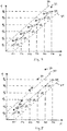
- Fig. 2 shows a diagram for recording target positions, namely target rotation angles ⁇ , each of which is assigned a target torque M.
- target rotation angles ⁇ 1 to ⁇ 6 the entire tubular bag machine with the transverse sealing unit 01 is first calibrated and the film tube 09 between the transverse sealing jaws 13a and 13b is removed. Subsequently, the transverse sealing unit 01 is given the set torques M1, M2, M3, M4, M5 and M6 one after the other by the drive control. As soon as the respective torque values M1 to M6 have been reached, the actual angle of rotation ⁇ determined by the position sensor system is determined and the determined actual angle of rotation is saved as the set angle of rotation ⁇ 1 to ⁇ 6 in the drive control.
- a setpoint rotation angle ⁇ 1 to ⁇ 6 is stored for each setpoint torque M1 to M6, the setpoint torques and setpoint angle of rotation each forming pairs of values.
- the value pairs plotted in the torque-angle of rotation diagram are all on a straight line. The slope of this straight line represents the spring stiffness of the translation between the drive motor 02 and the transverse sealing jaws 13a and 13b.
- Fig. 3 shows the diagram according to Fig. 2 supplemented by two tolerance thresholds 30 and 31.
- the two tolerance thresholds form a corridor around the straight line through the value pairs of the set torques M1 to M6 with the set angles of rotation ⁇ 1 to ⁇ 6.
- FIG. 4 The diagram shown shows the diagram according to Fig. 3 after a first functional check has been carried out. During this functional check, the film tube 02 between the transverse sealing jaws 13a and 13b is again removed and the transverse sealing jaws moved together. Then the target torque M1 to M6 is applied one after the other by the drive motor 02 and the resulting actual angle of rotation of the drive motor 02 is measured in each case.
- the corresponding value pairs 32 are in Fig. 4 marked circled. It can be seen that the six pairs of values 32 that result from the function check all lie on a straight line that is shifted upwards parallel to the straight line through the pairs of values 33 of the target torque and target angle of rotation (see FIG Fig. 3 ).
- This parallel displacement of the spring line can be based, for example, on the fact that when a new transverse sealing tool was installed, a somewhat different distance was implemented between the transverse sealing jaws 13a and 13b. However, since the value pairs 32 are all within the corridor between the tolerance thresholds 30 and 31, an error message does not need to be output.
- Fig. 5 shows the value pairs 34 of a second function check, which represents the actual position, namely the actual angle of rotation together with the respectively applied setpoint torque M1 to M6. It can be seen that the pairs of values 34 also all lie on a straight line, this straight line resulting in a different slope than the straight line through the pairs of values 33 made up of the target torque and target angle of rotation. This other slope of the Spring line through the value pairs 34 can be caused, for example, by the installation of a stiffer component, for example a somewhat stiffer transverse sealing tool. Since the upper three pairs of values 34 lie outside the corridor between the tolerance thresholds 30 and 31, an error message is output in this case so that the operating personnel can carry out an error diagnosis.
Landscapes
- Engineering & Computer Science (AREA)
- Mechanical Engineering (AREA)
- Package Closures (AREA)
- Containers And Plastic Fillers For Packaging (AREA)
Claims (15)
- Procédé pour contrôler la fonction d'une machine de sachet tubulaire, la machine de sachet tubulaire comprenant un système de commande d'entraînement et plusieurs unités d'entraînement électroniques qui sont commandées indépendamment les unes des autres par le système de commande d'entraînement et qui entrainent des éléments fonctionnels différents de la machine d'emballage de manière synchrone au niveau du temps de cycle lorsque des séquences de mouvement prédéfinies sont exécutées, et une unité d'entraînement étant réalisée à la manière d'une unité de scellage transversal, et l'unité de scellage transversal comprenant au moins un moteur d'entraînement (02) et deux mâchoires de scellage (13a, 13b) transversal qui sont entraînées l'une par rapport à l'autre par le moteur d'entraînement (02) et au moyen desquelles un tube de film (09) est soudé transversalement à la direction du convoyage (21), et la position (cp) du moteur d'entraînement (02) étant mesurée indirectement ou directement au moyen d'un capteur de position,
caractérisé en ce que
le couple d'entraînement (M) du moteur d'entraînement (02) est mesuré indirectement ou directement au moyen d'un régulateur d'entraînement, le procédé comprenant les étapes du procédé consistant à :a) retirer le tube de film (09) de la zone de scellage entre les deux mâchoires de scellage (13a, 13b) transversal ;b) fermer les mâchoires de scellage (13a, 13b) transversal conformément à un couple de consigne prédéfini et mémorisé dans le système de commande d'entraînement ;c) mesurer la position réelle du moteur d'entraînement (02) après avoir atteint le couple de consigne ;d) comparer la position réelle mesurée avec une position de consigne mémorisée dans le système de commande d'entraînement et attribuée au couple de consigne prédéfini. - Procédé selon la revendication 1,
caractérisé en ce que
plusieurs couples de consigne, dont chacun a une position de consigne attribuée, sont mémorisés dans le système de commande d'entraînement, les étapes du procédé b), c) et d) étant répétées l'une après l'autre pour les couples de consigne différents et leurs positions de consigne attribuées. - Procédé selon la revendication 1 ou 2,
caractérisé en ce que
pour déterminer les positions de consigne, l'unité de scellage transversal est d'abord calibrée et, ensuite, les positions réelles atteintes sont mesurées pour des couples de consigne différents, les positions réelles mesurées de cette manière étant mémorisées dans le système de commande d'entraînement comme positions de consigne attribuées aux couples de consigne respectifs. - Procédé pour contrôler la fonction d'une machine de sachet tubulaire, la machine de sachet tubulaire comprenant un système de commande d'entraînement et plusieurs unités d'entraînement électroniques qui sont commandées indépendamment les unes des autres par le système de commande d'entraînement et qui entrainent des éléments fonctionnels différents de la machine d'emballage de manière synchrone au niveau du temps de cycle lorsque des séquences de mouvement prédéfinies sont exécutées, et une unité d'entraînement étant réalisée à la manière d'une unité de scellage transversal, et l'unité de scellage transversal comprenant au moins un moteur d'entraînement (02) et deux mâchoires de scellage (13a, 13b) transversal qui sont entraînées l'une par rapport à l'autre par le moteur d'entraînement (02) et au moyen desquelles un tube de film (09) est soudé transversalement à la direction du convoyage (21), et la position (cp) du moteur d'entraînement (02) étant mesurée indirectement ou directement au moyen d'un capteur de position,
caractérisé en ce que
le couple d'entraînement (M) du moteur d'entraînement (02) est mesuré indirectement ou directement au moyen d'un régulateur d'entraînement, le procédé comprenant les étapes du procédé consistant à :a) retirer le tube de film (09) de la zone de scellage entre les deux mâchoires de scellage (13a, 13b) transversal ;b) fermer les mâchoires de scellage (13a, 13b) transversal conformément à une position de consigne prédéfinie et mémorisée dans le système de commande d'entraînement ;c) mesurer le couple réel du moteur d'entraînement après avoir atteint la position de consigne ;d) comparer le couple réel mesuré avec un couple de consigne mémorisé dans le système de commande d'entraînement et attribué à la position de consigne prédéfinie. - Procédé selon la revendication 4,
caractérisé en ce que
plusieurs positions de consigne, dont chacune a un couple de consigne attribué, sont mémorisées dans le système de commande d'entraînement, les étapes du procédé b), c) et d) étant répétées l'une après l'autre pour les positions de consigne différentes et leurs couples de consigne attribués. - Procédé selon la revendication 4 ou 5,
caractérisé en ce que
pour déterminer les couples de consigne, l'unité de scellage transversal est d'abord calibrée et, ensuite, les couples réelles atteints sont mesurés pour des positions de consigne différentes, les couples réels mesurés de cette manière étant mémorisés dans le système de commande d'entraînement comme couples de consigne attribués aux positions de consigne respectives. - Procédé selon l'une quelconque des revendications 1 à 6,
caractérisé en ce que
les étapes de procédé a), b), c) et d) sont effectuées à une température de référence mémorisée dans le système de commande d'entraînement, notamment à température ambiante. - Procédé selon la revendication 7,
caractérisé en ce que
la température de référence correspond à la température mesurée à laquelle les positions de consigne ou les couples de consigne ont été déterminés en mesurant des positions réelles ou des couples réels de l'unité de scellage transversal calibrée. - Procédé selon l'une quelconque des revendications 1 à 8,
caractérisé en ce
qu'une différence déterminée dans l'étape de procédé d) entre la position de consigne et la position réelle ou entre le couple de consigne et le couple réel est comparée avec un seuil de tolérance (30, 31) mémorisé dans le système de commande d'entraînement, un défaut étant signalé lorsque le seuil de tolérance (30, 31) est excédé. - Procédé selon l'une quelconque des revendications 1 à 9,
caractérisé en ce que
la position réelle est mesurée directement au moyen d'un capteur d'angle de rotation. - Procédé selon l'une quelconque des revendications 1 à 10,
caractérisé en ce que
le couple réel est mesuré indirectement par le régulateur d'entraînement du moteur d'entraînement (02). - Procédé selon l'une quelconque des revendications 1 à 11,
caractérisé en ce que
les étapes de procédé a), b), c) et d) sont effectuées après un remplacement des mâchoires de scellage transversal. - Procédé selon l'une quelconque des revendications 1 à 11,
caractérisé en ce que
les étapes de procédé a),b), c) et d) sont effectuées après un dérangement du fonctionnement de la machine de sachet tubulaire. - Procédé selon l'une quelconque des revendications 1 à 13,
caractérisé en ce
qu'une séquence de mouvement est exécutée par les unités d'entraînement pour la production intermittente de sachets tubulaires. - Procédé selon l'une quelconque des revendications 1 à 13,
caractérisé en ce
qu'une séquence de mouvement est exécutée par les unités d'entraînement pour la production continue de sachets tubulaires.
Applications Claiming Priority (2)
| Application Number | Priority Date | Filing Date | Title |
|---|---|---|---|
| DE102017208766.8A DE102017208766A1 (de) | 2017-05-23 | 2017-05-23 | Verfahren zur Funktionsüberprüfung einer Schlauchbeutelmaschine |
| PCT/EP2018/062682 WO2018215256A1 (fr) | 2017-05-23 | 2018-05-16 | Procédé de vérification du fonctionnement d'une ensacheuse tubulaire |
Publications (3)
| Publication Number | Publication Date |
|---|---|
| EP3630459A1 EP3630459A1 (fr) | 2020-04-08 |
| EP3630459B1 true EP3630459B1 (fr) | 2021-08-11 |
| EP3630459B9 EP3630459B9 (fr) | 2022-08-17 |
Family
ID=62530178
Family Applications (1)
| Application Number | Title | Priority Date | Filing Date |
|---|---|---|---|
| EP18729333.7A Active EP3630459B9 (fr) | 2017-05-23 | 2018-05-16 | Procédés de vérification du fonctionnement d'une ensacheuse tubulaire |
Country Status (5)
| Country | Link |
|---|---|
| US (1) | US11370573B2 (fr) |
| EP (1) | EP3630459B9 (fr) |
| DE (1) | DE102017208766A1 (fr) |
| ES (1) | ES2887265T3 (fr) |
| WO (1) | WO2018215256A1 (fr) |
Families Citing this family (3)
| Publication number | Priority date | Publication date | Assignee | Title |
|---|---|---|---|---|
| JP7113564B2 (ja) * | 2019-04-05 | 2022-08-05 | 伊東電機株式会社 | コンベヤシステム、原因情報報知装置、原因情報報知装置用のプログラム、及び原因情報報知装置用のプログラムを記録したコンピュータ読み取り可能な記録媒体 |
| BE1030346B1 (nl) * | 2022-03-15 | 2023-10-16 | Engilico Eng Solutions Nv | Werkwijze en inrichting voor detecteren van defecten bij het verzegelen van een folie omvattende verpakking |
| CN116572216A (zh) * | 2023-06-05 | 2023-08-11 | 广州达意隆包装机械股份有限公司 | 一种自立袋夹具控制系统、控制方法、装置及存储介质 |
Family Cites Families (10)
| Publication number | Priority date | Publication date | Assignee | Title |
|---|---|---|---|---|
| DE3907208A1 (de) * | 1988-10-18 | 1990-04-19 | Rovema Gmbh | Verfahren und vorrichtung zur steuerung der bewegung von querschweissbacken einer schlauchbeutelmaschine |
| US5322586A (en) * | 1992-05-11 | 1994-06-21 | Reynolds Metals Company | Computer controller heat-sealing machine |
| JP3473861B2 (ja) * | 1993-12-28 | 2003-12-08 | 株式会社イシダ | 包材の封止部に介在する介在物の有無の判定方法 |
| WO1996040558A1 (fr) * | 1995-06-07 | 1996-12-19 | Tetra Laval Holdings & Finance S.A. | Systeme de diagnostic pour un appareil mu par un servomoteur |
| US5653085A (en) | 1996-05-20 | 1997-08-05 | Ibaraki Seiki Machinery Company, Ltd. | Sealing device for packaging machine |
| US5836136A (en) | 1997-03-18 | 1998-11-17 | Kliklok Corporation | Seal integrity monitoring and adaptive control method and apparatus |
| JP2006193176A (ja) | 2005-01-13 | 2006-07-27 | Ishida Co Ltd | 製袋包装機 |
| DE102007004140B4 (de) | 2007-01-26 | 2018-04-26 | Rovema Gmbh | Schlauchbeutelmaschine |
| US20100108249A1 (en) | 2008-11-05 | 2010-05-06 | Cmd Corporation | Method and Apparatus For Making Sealed Pouches |
| DE102013203295A1 (de) | 2013-02-27 | 2014-08-28 | Rovema Gmbh | Schlauchbeutelmaschine mit kombiniertem Antrieb für zwei Achsen |
-
2017
- 2017-05-23 DE DE102017208766.8A patent/DE102017208766A1/de not_active Ceased
-
2018
- 2018-05-16 EP EP18729333.7A patent/EP3630459B9/fr active Active
- 2018-05-16 WO PCT/EP2018/062682 patent/WO2018215256A1/fr not_active Ceased
- 2018-05-16 ES ES18729333T patent/ES2887265T3/es active Active
- 2018-05-16 US US16/613,358 patent/US11370573B2/en active Active
Also Published As
| Publication number | Publication date |
|---|---|
| US11370573B2 (en) | 2022-06-28 |
| EP3630459B9 (fr) | 2022-08-17 |
| US20210078745A1 (en) | 2021-03-18 |
| DE102017208766A1 (de) | 2018-11-29 |
| ES2887265T3 (es) | 2021-12-22 |
| WO2018215256A1 (fr) | 2018-11-29 |
| EP3630459A1 (fr) | 2020-04-08 |
Similar Documents
| Publication | Publication Date | Title |
|---|---|---|
| DE102013214019B3 (de) | Spannvorrichtung zum Positionieren von Werkstücken, Werkzeugmaschine mit einer derartigen Spannvorrichtung, Verfahren zum Positionieren von Werkstücken mittels einer derartigen Spannvorrichtung | |
| EP3630459B1 (fr) | Procédés de vérification du fonctionnement d'une ensacheuse tubulaire | |
| EP2853354B1 (fr) | Régulation de position avec prévention de collision et adaptation d'un modèle de machine à la machine réelle | |
| DE102020208961B3 (de) | Verfahren zur Ausrichtung eines Roboterarms | |
| DE19723650C2 (de) | Verfahren und Vorrichtung zur Überwachung eines Stellgeräts | |
| DE20321807U1 (de) | Vorrichtung zum Steuern der Andruckkraft einer Schweißzange | |
| DE102014226008B3 (de) | Verfahren zur Überprüfung der Zuordnung eines Antriebs zu einer Steuereinrichtung | |
| EP3630462B1 (fr) | Procédé de commande d'une ensacheuse tubulaire et ensacheuse tubulaire | |
| DE102019212631A1 (de) | Verfahren zur Zustandsüberwachung einer Vorrichtung und Vorrichtung | |
| EP3630460B1 (fr) | Procédés de surveillance du fonctionnement d'une ensacheuse tubulaire | |
| DE102011001167A1 (de) | Verfahren zum Betreiben einer Schweißvorrichtung, insbesondere eines wärmeimpulsgesteuerten und/oder dauerbeheizten Folienschweiß- und/oder Heißsiegelgerätes mit vorwählbarer elektronischer, prozessorgesteuerter Anpressdruck- und Temperaturregelung und Vorrichtung hierzu | |
| EP1806837B1 (fr) | Méthode pour tester la fonction de freinage d'un entraînement du robot | |
| EP3747734A1 (fr) | Détermination d'une position de direction dans un système de direction de véhicule à engrenage variable | |
| DE10354526A1 (de) | Industrieroboter mit Reibschweißeinheit und Verfahren zur Steuerung | |
| DE102004047207A1 (de) | Verfahren und Vorrichtung zum Bewegen einer Schweißbacke | |
| DE102005013786A1 (de) | Maschinenfähigkeitsuntersuchung in Winkelschritten | |
| DE102014004877B3 (de) | Antriebssystem und Verfahren zum Betreiben eines Antriebssystems | |
| DE112022005622T5 (de) | Einrichtung zur Herstellung von Behältern, die mit einer Flüssigkeit gefüllt und versiegelt sind | |
| EP3258331B1 (fr) | Surveillance d'une machine | |
| DE10204183A1 (de) | Verfahren zum Ermitteln einer fehlerbehafteten Ansteuerung eines über einen Stellantrieb angetriebenen Bauteils | |
| EP2000875B1 (fr) | Procédé destiné à l'étalonnage automatique d'un dispositif de réglage pour une introduction de liquide réglable | |
| DE10104099A1 (de) | Getriebe und ein Verfahren hierfür | |
| EP3127683B1 (fr) | Poste de soudure destine a souder des sachets en film et procede associe | |
| EP4177134B1 (fr) | Système de direction électromécanique et procédé de fonctionnement d'un système de direction électromécanique avec vérification de plausibilité de valeurs de capteur d'angle | |
| DE102019007101A1 (de) | Vorrichtung und Verfahren zur Bestimmung der Lebensdauer eines mechatronischen Systems sowie Roboter |
Legal Events
| Date | Code | Title | Description |
|---|---|---|---|
| STAA | Information on the status of an ep patent application or granted ep patent |
Free format text: STATUS: UNKNOWN |
|
| STAA | Information on the status of an ep patent application or granted ep patent |
Free format text: STATUS: THE INTERNATIONAL PUBLICATION HAS BEEN MADE |
|
| PUAI | Public reference made under article 153(3) epc to a published international application that has entered the european phase |
Free format text: ORIGINAL CODE: 0009012 |
|
| STAA | Information on the status of an ep patent application or granted ep patent |
Free format text: STATUS: REQUEST FOR EXAMINATION WAS MADE |
|
| 17P | Request for examination filed |
Effective date: 20191205 |
|
| AK | Designated contracting states |
Kind code of ref document: A1 Designated state(s): AL AT BE BG CH CY CZ DE DK EE ES FI FR GB GR HR HU IE IS IT LI LT LU LV MC MK MT NL NO PL PT RO RS SE SI SK SM TR |
|
| AX | Request for extension of the european patent |
Extension state: BA ME |
|
| DAV | Request for validation of the european patent (deleted) | ||
| DAX | Request for extension of the european patent (deleted) | ||
| GRAP | Despatch of communication of intention to grant a patent |
Free format text: ORIGINAL CODE: EPIDOSNIGR1 |
|
| STAA | Information on the status of an ep patent application or granted ep patent |
Free format text: STATUS: GRANT OF PATENT IS INTENDED |
|
| RIC1 | Information provided on ipc code assigned before grant |
Ipc: B29C 65/02 20060101AFI20210218BHEP Ipc: B65B 51/30 20060101ALI20210218BHEP Ipc: B65B 57/00 20060101ALI20210218BHEP Ipc: B65B 65/02 20060101ALI20210218BHEP |
|
| INTG | Intention to grant announced |
Effective date: 20210305 |
|
| GRAS | Grant fee paid |
Free format text: ORIGINAL CODE: EPIDOSNIGR3 |
|
| GRAA | (expected) grant |
Free format text: ORIGINAL CODE: 0009210 |
|
| STAA | Information on the status of an ep patent application or granted ep patent |
Free format text: STATUS: THE PATENT HAS BEEN GRANTED |
|
| AK | Designated contracting states |
Kind code of ref document: B1 Designated state(s): AL AT BE BG CH CY CZ DE DK EE ES FI FR GB GR HR HU IE IS IT LI LT LU LV MC MK MT NL NO PL PT RO RS SE SI SK SM TR |
|
| REG | Reference to a national code |
Ref country code: CH Ref legal event code: EP |
|
| REG | Reference to a national code |
Ref country code: DE Ref legal event code: R096 Ref document number: 502018006546 Country of ref document: DE |
|
| REG | Reference to a national code |
Ref country code: IE Ref legal event code: FG4D Free format text: LANGUAGE OF EP DOCUMENT: GERMAN Ref country code: AT Ref legal event code: REF Ref document number: 1418947 Country of ref document: AT Kind code of ref document: T Effective date: 20210915 |
|
| REG | Reference to a national code |
Ref country code: NL Ref legal event code: FP |
|
| REG | Reference to a national code |
Ref country code: LT Ref legal event code: MG9D |
|
| REG | Reference to a national code |
Ref country code: ES Ref legal event code: FG2A Ref document number: 2887265 Country of ref document: ES Kind code of ref document: T3 Effective date: 20211222 |
|
| PG25 | Lapsed in a contracting state [announced via postgrant information from national office to epo] |
Ref country code: FI Free format text: LAPSE BECAUSE OF FAILURE TO SUBMIT A TRANSLATION OF THE DESCRIPTION OR TO PAY THE FEE WITHIN THE PRESCRIBED TIME-LIMIT Effective date: 20210811 Ref country code: HR Free format text: LAPSE BECAUSE OF FAILURE TO SUBMIT A TRANSLATION OF THE DESCRIPTION OR TO PAY THE FEE WITHIN THE PRESCRIBED TIME-LIMIT Effective date: 20210811 Ref country code: RS Free format text: LAPSE BECAUSE OF FAILURE TO SUBMIT A TRANSLATION OF THE DESCRIPTION OR TO PAY THE FEE WITHIN THE PRESCRIBED TIME-LIMIT Effective date: 20210811 Ref country code: SE Free format text: LAPSE BECAUSE OF FAILURE TO SUBMIT A TRANSLATION OF THE DESCRIPTION OR TO PAY THE FEE WITHIN THE PRESCRIBED TIME-LIMIT Effective date: 20210811 Ref country code: PT Free format text: LAPSE BECAUSE OF FAILURE TO SUBMIT A TRANSLATION OF THE DESCRIPTION OR TO PAY THE FEE WITHIN THE PRESCRIBED TIME-LIMIT Effective date: 20211213 Ref country code: NO Free format text: LAPSE BECAUSE OF FAILURE TO SUBMIT A TRANSLATION OF THE DESCRIPTION OR TO PAY THE FEE WITHIN THE PRESCRIBED TIME-LIMIT Effective date: 20211111 Ref country code: BG Free format text: LAPSE BECAUSE OF FAILURE TO SUBMIT A TRANSLATION OF THE DESCRIPTION OR TO PAY THE FEE WITHIN THE PRESCRIBED TIME-LIMIT Effective date: 20211111 Ref country code: LT Free format text: LAPSE BECAUSE OF FAILURE TO SUBMIT A TRANSLATION OF THE DESCRIPTION OR TO PAY THE FEE WITHIN THE PRESCRIBED TIME-LIMIT Effective date: 20210811 |
|
| PG25 | Lapsed in a contracting state [announced via postgrant information from national office to epo] |
Ref country code: PL Free format text: LAPSE BECAUSE OF FAILURE TO SUBMIT A TRANSLATION OF THE DESCRIPTION OR TO PAY THE FEE WITHIN THE PRESCRIBED TIME-LIMIT Effective date: 20210811 Ref country code: LV Free format text: LAPSE BECAUSE OF FAILURE TO SUBMIT A TRANSLATION OF THE DESCRIPTION OR TO PAY THE FEE WITHIN THE PRESCRIBED TIME-LIMIT Effective date: 20210811 Ref country code: GR Free format text: LAPSE BECAUSE OF FAILURE TO SUBMIT A TRANSLATION OF THE DESCRIPTION OR TO PAY THE FEE WITHIN THE PRESCRIBED TIME-LIMIT Effective date: 20211112 |
|
| PG25 | Lapsed in a contracting state [announced via postgrant information from national office to epo] |
Ref country code: DK Free format text: LAPSE BECAUSE OF FAILURE TO SUBMIT A TRANSLATION OF THE DESCRIPTION OR TO PAY THE FEE WITHIN THE PRESCRIBED TIME-LIMIT Effective date: 20210811 |
|
| REG | Reference to a national code |
Ref country code: DE Ref legal event code: R097 Ref document number: 502018006546 Country of ref document: DE |
|
| PG25 | Lapsed in a contracting state [announced via postgrant information from national office to epo] |
Ref country code: SM Free format text: LAPSE BECAUSE OF FAILURE TO SUBMIT A TRANSLATION OF THE DESCRIPTION OR TO PAY THE FEE WITHIN THE PRESCRIBED TIME-LIMIT Effective date: 20210811 Ref country code: SK Free format text: LAPSE BECAUSE OF FAILURE TO SUBMIT A TRANSLATION OF THE DESCRIPTION OR TO PAY THE FEE WITHIN THE PRESCRIBED TIME-LIMIT Effective date: 20210811 Ref country code: RO Free format text: LAPSE BECAUSE OF FAILURE TO SUBMIT A TRANSLATION OF THE DESCRIPTION OR TO PAY THE FEE WITHIN THE PRESCRIBED TIME-LIMIT Effective date: 20210811 Ref country code: EE Free format text: LAPSE BECAUSE OF FAILURE TO SUBMIT A TRANSLATION OF THE DESCRIPTION OR TO PAY THE FEE WITHIN THE PRESCRIBED TIME-LIMIT Effective date: 20210811 Ref country code: AL Free format text: LAPSE BECAUSE OF FAILURE TO SUBMIT A TRANSLATION OF THE DESCRIPTION OR TO PAY THE FEE WITHIN THE PRESCRIBED TIME-LIMIT Effective date: 20210811 |
|
| PLBE | No opposition filed within time limit |
Free format text: ORIGINAL CODE: 0009261 |
|
| STAA | Information on the status of an ep patent application or granted ep patent |
Free format text: STATUS: NO OPPOSITION FILED WITHIN TIME LIMIT |
|
| 26N | No opposition filed |
Effective date: 20220512 |
|
| REG | Reference to a national code |
Ref country code: CH Ref legal event code: PK Free format text: BERICHTIGUNG B9 |
|
| PG25 | Lapsed in a contracting state [announced via postgrant information from national office to epo] |
Ref country code: SI Free format text: LAPSE BECAUSE OF FAILURE TO SUBMIT A TRANSLATION OF THE DESCRIPTION OR TO PAY THE FEE WITHIN THE PRESCRIBED TIME-LIMIT Effective date: 20210811 |
|
| REG | Reference to a national code |
Ref country code: CH Ref legal event code: PL |
|
| REG | Reference to a national code |
Ref country code: BE Ref legal event code: MM Effective date: 20220531 |
|
| PG25 | Lapsed in a contracting state [announced via postgrant information from national office to epo] |
Ref country code: MC Free format text: LAPSE BECAUSE OF FAILURE TO SUBMIT A TRANSLATION OF THE DESCRIPTION OR TO PAY THE FEE WITHIN THE PRESCRIBED TIME-LIMIT Effective date: 20210811 Ref country code: LU Free format text: LAPSE BECAUSE OF NON-PAYMENT OF DUE FEES Effective date: 20220516 Ref country code: LI Free format text: LAPSE BECAUSE OF NON-PAYMENT OF DUE FEES Effective date: 20220531 Ref country code: CH Free format text: LAPSE BECAUSE OF NON-PAYMENT OF DUE FEES Effective date: 20220531 |
|
| PG25 | Lapsed in a contracting state [announced via postgrant information from national office to epo] |
Ref country code: IE Free format text: LAPSE BECAUSE OF NON-PAYMENT OF DUE FEES Effective date: 20220516 |
|
| PG25 | Lapsed in a contracting state [announced via postgrant information from national office to epo] |
Ref country code: BE Free format text: LAPSE BECAUSE OF NON-PAYMENT OF DUE FEES Effective date: 20220531 |
|
| P01 | Opt-out of the competence of the unified patent court (upc) registered |
Effective date: 20230524 |
|
| PG25 | Lapsed in a contracting state [announced via postgrant information from national office to epo] |
Ref country code: MK Free format text: LAPSE BECAUSE OF FAILURE TO SUBMIT A TRANSLATION OF THE DESCRIPTION OR TO PAY THE FEE WITHIN THE PRESCRIBED TIME-LIMIT Effective date: 20210811 Ref country code: CY Free format text: LAPSE BECAUSE OF FAILURE TO SUBMIT A TRANSLATION OF THE DESCRIPTION OR TO PAY THE FEE WITHIN THE PRESCRIBED TIME-LIMIT Effective date: 20210811 |
|
| PG25 | Lapsed in a contracting state [announced via postgrant information from national office to epo] |
Ref country code: HU Free format text: LAPSE BECAUSE OF FAILURE TO SUBMIT A TRANSLATION OF THE DESCRIPTION OR TO PAY THE FEE WITHIN THE PRESCRIBED TIME-LIMIT; INVALID AB INITIO Effective date: 20180516 |
|
| REG | Reference to a national code |
Ref country code: AT Ref legal event code: MM01 Ref document number: 1418947 Country of ref document: AT Kind code of ref document: T Effective date: 20230516 |
|
| PG25 | Lapsed in a contracting state [announced via postgrant information from national office to epo] |
Ref country code: AT Free format text: LAPSE BECAUSE OF NON-PAYMENT OF DUE FEES Effective date: 20230516 |
|
| PG25 | Lapsed in a contracting state [announced via postgrant information from national office to epo] |
Ref country code: AT Free format text: LAPSE BECAUSE OF NON-PAYMENT OF DUE FEES Effective date: 20230516 |
|
| PG25 | Lapsed in a contracting state [announced via postgrant information from national office to epo] |
Ref country code: MT Free format text: LAPSE BECAUSE OF FAILURE TO SUBMIT A TRANSLATION OF THE DESCRIPTION OR TO PAY THE FEE WITHIN THE PRESCRIBED TIME-LIMIT Effective date: 20210811 |
|
| PGFP | Annual fee paid to national office [announced via postgrant information from national office to epo] |
Ref country code: NL Payment date: 20250522 Year of fee payment: 8 |
|
| PGFP | Annual fee paid to national office [announced via postgrant information from national office to epo] |
Ref country code: GB Payment date: 20250522 Year of fee payment: 8 Ref country code: ES Payment date: 20250616 Year of fee payment: 8 |
|
| PGFP | Annual fee paid to national office [announced via postgrant information from national office to epo] |
Ref country code: IT Payment date: 20250530 Year of fee payment: 8 |
|
| PGFP | Annual fee paid to national office [announced via postgrant information from national office to epo] |
Ref country code: FR Payment date: 20250523 Year of fee payment: 8 |
|
| PGFP | Annual fee paid to national office [announced via postgrant information from national office to epo] |
Ref country code: CZ Payment date: 20250430 Year of fee payment: 8 |
|
| PGFP | Annual fee paid to national office [announced via postgrant information from national office to epo] |
Ref country code: DE Payment date: 20250722 Year of fee payment: 8 |
|
| PG25 | Lapsed in a contracting state [announced via postgrant information from national office to epo] |
Ref country code: TR Free format text: LAPSE BECAUSE OF FAILURE TO SUBMIT A TRANSLATION OF THE DESCRIPTION OR TO PAY THE FEE WITHIN THE PRESCRIBED TIME-LIMIT Effective date: 20210811 |
|
| PGFP | Annual fee paid to national office [announced via postgrant information from national office to epo] |
Ref country code: AT Payment date: 20260410 Year of fee payment: 5 |