EP3631576B1 - Commande de densité de puissance optique dans un laser couplé à une fibre - Google Patents
Commande de densité de puissance optique dans un laser couplé à une fibre Download PDFInfo
- Publication number
- EP3631576B1 EP3631576B1 EP18805491.0A EP18805491A EP3631576B1 EP 3631576 B1 EP3631576 B1 EP 3631576B1 EP 18805491 A EP18805491 A EP 18805491A EP 3631576 B1 EP3631576 B1 EP 3631576B1
- Authority
- EP
- European Patent Office
- Prior art keywords
- fiber
- length
- optical beam
- perturbation
- optical
- Prior art date
- Legal status (The legal status is an assumption and is not a legal conclusion. Google has not performed a legal analysis and makes no representation as to the accuracy of the status listed.)
- Active
Links
Images


Classifications
-
- G—PHYSICS
- G02—OPTICS
- G02B—OPTICAL ELEMENTS, SYSTEMS OR APPARATUS
- G02B27/00—Optical systems or apparatus not provided for by any of the groups G02B1/00 - G02B26/00, G02B30/00
- G02B27/09—Beam shaping, e.g. changing the cross-sectional area, not otherwise provided for
- G02B27/0927—Systems for changing the beam intensity distribution, e.g. Gaussian to top-hat
-
- G—PHYSICS
- G02—OPTICS
- G02F—OPTICAL DEVICES OR ARRANGEMENTS FOR THE CONTROL OF LIGHT BY MODIFICATION OF THE OPTICAL PROPERTIES OF THE MEDIA OF THE ELEMENTS INVOLVED THEREIN; NON-LINEAR OPTICS; FREQUENCY-CHANGING OF LIGHT; OPTICAL LOGIC ELEMENTS; OPTICAL ANALOGUE/DIGITAL CONVERTERS
- G02F1/00—Devices or arrangements for the control of the intensity, colour, phase, polarisation or direction of light arriving from an independent light source, e.g. switching, gating or modulating; Non-linear optics
- G02F1/01—Devices or arrangements for the control of the intensity, colour, phase, polarisation or direction of light arriving from an independent light source, e.g. switching, gating or modulating; Non-linear optics for the control of the intensity, phase, polarisation or colour
- G02F1/011—Devices or arrangements for the control of the intensity, colour, phase, polarisation or direction of light arriving from an independent light source, e.g. switching, gating or modulating; Non-linear optics for the control of the intensity, phase, polarisation or colour in optical waveguides, not otherwise provided for in this subclass
- G02F1/0115—Devices or arrangements for the control of the intensity, colour, phase, polarisation or direction of light arriving from an independent light source, e.g. switching, gating or modulating; Non-linear optics for the control of the intensity, phase, polarisation or colour in optical waveguides, not otherwise provided for in this subclass in optical fibres
-
- B—PERFORMING OPERATIONS; TRANSPORTING
- B22—CASTING; POWDER METALLURGY
- B22F—WORKING METALLIC POWDER; MANUFACTURE OF ARTICLES FROM METALLIC POWDER; MAKING METALLIC POWDER; APPARATUS OR DEVICES SPECIALLY ADAPTED FOR METALLIC POWDER
- B22F10/00—Additive manufacturing of workpieces or articles from metallic powder
- B22F10/20—Direct sintering or melting
-
- B—PERFORMING OPERATIONS; TRANSPORTING
- B22—CASTING; POWDER METALLURGY
- B22F—WORKING METALLIC POWDER; MANUFACTURE OF ARTICLES FROM METALLIC POWDER; MAKING METALLIC POWDER; APPARATUS OR DEVICES SPECIALLY ADAPTED FOR METALLIC POWDER
- B22F10/00—Additive manufacturing of workpieces or articles from metallic powder
- B22F10/30—Process control
- B22F10/31—Calibration of process steps or apparatus settings, e.g. before or during manufacturing
-
- B—PERFORMING OPERATIONS; TRANSPORTING
- B22—CASTING; POWDER METALLURGY
- B22F—WORKING METALLIC POWDER; MANUFACTURE OF ARTICLES FROM METALLIC POWDER; MAKING METALLIC POWDER; APPARATUS OR DEVICES SPECIALLY ADAPTED FOR METALLIC POWDER
- B22F10/00—Additive manufacturing of workpieces or articles from metallic powder
- B22F10/30—Process control
- B22F10/36—Process control of energy beam parameters
-
- B—PERFORMING OPERATIONS; TRANSPORTING
- B22—CASTING; POWDER METALLURGY
- B22F—WORKING METALLIC POWDER; MANUFACTURE OF ARTICLES FROM METALLIC POWDER; MAKING METALLIC POWDER; APPARATUS OR DEVICES SPECIALLY ADAPTED FOR METALLIC POWDER
- B22F3/00—Manufacture of workpieces or articles from metallic powder characterised by the manner of compacting or sintering; Apparatus specially adapted therefor ; Presses and furnaces
- B22F3/10—Sintering only
- B22F3/11—Making porous workpieces or articles
- B22F3/1103—Making porous workpieces or articles with particular physical characteristics
- B22F3/1109—Inhomogenous pore distribution
-
- B—PERFORMING OPERATIONS; TRANSPORTING
- B22—CASTING; POWDER METALLURGY
- B22F—WORKING METALLIC POWDER; MANUFACTURE OF ARTICLES FROM METALLIC POWDER; MAKING METALLIC POWDER; APPARATUS OR DEVICES SPECIALLY ADAPTED FOR METALLIC POWDER
- B22F3/00—Manufacture of workpieces or articles from metallic powder characterised by the manner of compacting or sintering; Apparatus specially adapted therefor ; Presses and furnaces
- B22F3/24—After-treatment of workpieces or articles
-
- B—PERFORMING OPERATIONS; TRANSPORTING
- B23—MACHINE TOOLS; METAL-WORKING NOT OTHERWISE PROVIDED FOR
- B23K—SOLDERING OR UNSOLDERING; WELDING; CLADDING OR PLATING BY SOLDERING OR WELDING; CUTTING BY APPLYING HEAT LOCALLY, e.g. FLAME CUTTING; WORKING BY LASER BEAM
- B23K26/00—Working by laser beam, e.g. welding, cutting or boring
- B23K26/02—Positioning or observing the workpiece, e.g. with respect to the point of impact; Aligning, aiming or focusing the laser beam
- B23K26/03—Observing, e.g. monitoring, the workpiece
- B23K26/032—Observing, e.g. monitoring, the workpiece using optical means
-
- B—PERFORMING OPERATIONS; TRANSPORTING
- B23—MACHINE TOOLS; METAL-WORKING NOT OTHERWISE PROVIDED FOR
- B23K—SOLDERING OR UNSOLDERING; WELDING; CLADDING OR PLATING BY SOLDERING OR WELDING; CUTTING BY APPLYING HEAT LOCALLY, e.g. FLAME CUTTING; WORKING BY LASER BEAM
- B23K26/00—Working by laser beam, e.g. welding, cutting or boring
- B23K26/02—Positioning or observing the workpiece, e.g. with respect to the point of impact; Aligning, aiming or focusing the laser beam
- B23K26/03—Observing, e.g. monitoring, the workpiece
- B23K26/034—Observing the temperature of the workpiece
-
- B—PERFORMING OPERATIONS; TRANSPORTING
- B23—MACHINE TOOLS; METAL-WORKING NOT OTHERWISE PROVIDED FOR
- B23K—SOLDERING OR UNSOLDERING; WELDING; CLADDING OR PLATING BY SOLDERING OR WELDING; CUTTING BY APPLYING HEAT LOCALLY, e.g. FLAME CUTTING; WORKING BY LASER BEAM
- B23K26/00—Working by laser beam, e.g. welding, cutting or boring
- B23K26/02—Positioning or observing the workpiece, e.g. with respect to the point of impact; Aligning, aiming or focusing the laser beam
- B23K26/03—Observing, e.g. monitoring, the workpiece
- B23K26/0342—Observing magnetic fields related to the workpiece
-
- B—PERFORMING OPERATIONS; TRANSPORTING
- B23—MACHINE TOOLS; METAL-WORKING NOT OTHERWISE PROVIDED FOR
- B23K—SOLDERING OR UNSOLDERING; WELDING; CLADDING OR PLATING BY SOLDERING OR WELDING; CUTTING BY APPLYING HEAT LOCALLY, e.g. FLAME CUTTING; WORKING BY LASER BEAM
- B23K26/00—Working by laser beam, e.g. welding, cutting or boring
- B23K26/02—Positioning or observing the workpiece, e.g. with respect to the point of impact; Aligning, aiming or focusing the laser beam
- B23K26/06—Shaping the laser beam, e.g. by masks or multi-focusing
- B23K26/062—Shaping the laser beam, e.g. by masks or multi-focusing by direct control of the laser beam
-
- B—PERFORMING OPERATIONS; TRANSPORTING
- B23—MACHINE TOOLS; METAL-WORKING NOT OTHERWISE PROVIDED FOR
- B23K—SOLDERING OR UNSOLDERING; WELDING; CLADDING OR PLATING BY SOLDERING OR WELDING; CUTTING BY APPLYING HEAT LOCALLY, e.g. FLAME CUTTING; WORKING BY LASER BEAM
- B23K26/00—Working by laser beam, e.g. welding, cutting or boring
- B23K26/02—Positioning or observing the workpiece, e.g. with respect to the point of impact; Aligning, aiming or focusing the laser beam
- B23K26/06—Shaping the laser beam, e.g. by masks or multi-focusing
- B23K26/064—Shaping the laser beam, e.g. by masks or multi-focusing by means of optical elements, e.g. lenses, mirrors or prisms
-
- B—PERFORMING OPERATIONS; TRANSPORTING
- B23—MACHINE TOOLS; METAL-WORKING NOT OTHERWISE PROVIDED FOR
- B23K—SOLDERING OR UNSOLDERING; WELDING; CLADDING OR PLATING BY SOLDERING OR WELDING; CUTTING BY APPLYING HEAT LOCALLY, e.g. FLAME CUTTING; WORKING BY LASER BEAM
- B23K26/00—Working by laser beam, e.g. welding, cutting or boring
- B23K26/02—Positioning or observing the workpiece, e.g. with respect to the point of impact; Aligning, aiming or focusing the laser beam
- B23K26/06—Shaping the laser beam, e.g. by masks or multi-focusing
- B23K26/067—Dividing the beam into multiple beams, e.g. multi-focusing
-
- B—PERFORMING OPERATIONS; TRANSPORTING
- B23—MACHINE TOOLS; METAL-WORKING NOT OTHERWISE PROVIDED FOR
- B23K—SOLDERING OR UNSOLDERING; WELDING; CLADDING OR PLATING BY SOLDERING OR WELDING; CUTTING BY APPLYING HEAT LOCALLY, e.g. FLAME CUTTING; WORKING BY LASER BEAM
- B23K26/00—Working by laser beam, e.g. welding, cutting or boring
- B23K26/02—Positioning or observing the workpiece, e.g. with respect to the point of impact; Aligning, aiming or focusing the laser beam
- B23K26/06—Shaping the laser beam, e.g. by masks or multi-focusing
- B23K26/073—Shaping the laser spot
-
- B—PERFORMING OPERATIONS; TRANSPORTING
- B23—MACHINE TOOLS; METAL-WORKING NOT OTHERWISE PROVIDED FOR
- B23K—SOLDERING OR UNSOLDERING; WELDING; CLADDING OR PLATING BY SOLDERING OR WELDING; CUTTING BY APPLYING HEAT LOCALLY, e.g. FLAME CUTTING; WORKING BY LASER BEAM
- B23K26/00—Working by laser beam, e.g. welding, cutting or boring
- B23K26/20—Bonding
- B23K26/21—Bonding by welding
-
- B—PERFORMING OPERATIONS; TRANSPORTING
- B23—MACHINE TOOLS; METAL-WORKING NOT OTHERWISE PROVIDED FOR
- B23K—SOLDERING OR UNSOLDERING; WELDING; CLADDING OR PLATING BY SOLDERING OR WELDING; CUTTING BY APPLYING HEAT LOCALLY, e.g. FLAME CUTTING; WORKING BY LASER BEAM
- B23K26/00—Working by laser beam, e.g. welding, cutting or boring
- B23K26/34—Laser welding for purposes other than joining
- B23K26/342—Build-up welding
-
- B—PERFORMING OPERATIONS; TRANSPORTING
- B23—MACHINE TOOLS; METAL-WORKING NOT OTHERWISE PROVIDED FOR
- B23K—SOLDERING OR UNSOLDERING; WELDING; CLADDING OR PLATING BY SOLDERING OR WELDING; CUTTING BY APPLYING HEAT LOCALLY, e.g. FLAME CUTTING; WORKING BY LASER BEAM
- B23K26/00—Working by laser beam, e.g. welding, cutting or boring
- B23K26/36—Removing material
- B23K26/38—Removing material by boring or cutting
-
- B—PERFORMING OPERATIONS; TRANSPORTING
- B23—MACHINE TOOLS; METAL-WORKING NOT OTHERWISE PROVIDED FOR
- B23K—SOLDERING OR UNSOLDERING; WELDING; CLADDING OR PLATING BY SOLDERING OR WELDING; CUTTING BY APPLYING HEAT LOCALLY, e.g. FLAME CUTTING; WORKING BY LASER BEAM
- B23K26/00—Working by laser beam, e.g. welding, cutting or boring
- B23K26/70—Auxiliary operations or equipment
- B23K26/702—Auxiliary equipment
- B23K26/704—Beam dispersers, e.g. beam wells
-
- B—PERFORMING OPERATIONS; TRANSPORTING
- B29—WORKING OF PLASTICS; WORKING OF SUBSTANCES IN A PLASTIC STATE IN GENERAL
- B29C—SHAPING OR JOINING OF PLASTICS; SHAPING OF MATERIAL IN A PLASTIC STATE, NOT OTHERWISE PROVIDED FOR; AFTER-TREATMENT OF THE SHAPED PRODUCTS, e.g. REPAIRING
- B29C48/00—Extrusion moulding, i.e. expressing the moulding material through a die or nozzle which imparts the desired form; Apparatus therefor
- B29C48/03—Extrusion moulding, i.e. expressing the moulding material through a die or nozzle which imparts the desired form; Apparatus therefor characterised by the shape of the extruded material at extrusion
- B29C48/07—Flat, e.g. panels
- B29C48/08—Flat, e.g. panels flexible, e.g. films
-
- B—PERFORMING OPERATIONS; TRANSPORTING
- B29—WORKING OF PLASTICS; WORKING OF SUBSTANCES IN A PLASTIC STATE IN GENERAL
- B29C—SHAPING OR JOINING OF PLASTICS; SHAPING OF MATERIAL IN A PLASTIC STATE, NOT OTHERWISE PROVIDED FOR; AFTER-TREATMENT OF THE SHAPED PRODUCTS, e.g. REPAIRING
- B29C64/00—Additive manufacturing, i.e. manufacturing of three-dimensional [3D] objects by additive deposition, additive agglomeration or additive layering, e.g. by 3D printing, stereolithography or selective laser sintering
- B29C64/10—Processes of additive manufacturing
- B29C64/141—Processes of additive manufacturing using only solid materials
- B29C64/153—Processes of additive manufacturing using only solid materials using layers of powder being selectively joined, e.g. by selective laser sintering or melting
-
- B—PERFORMING OPERATIONS; TRANSPORTING
- B29—WORKING OF PLASTICS; WORKING OF SUBSTANCES IN A PLASTIC STATE IN GENERAL
- B29C—SHAPING OR JOINING OF PLASTICS; SHAPING OF MATERIAL IN A PLASTIC STATE, NOT OTHERWISE PROVIDED FOR; AFTER-TREATMENT OF THE SHAPED PRODUCTS, e.g. REPAIRING
- B29C64/00—Additive manufacturing, i.e. manufacturing of three-dimensional [3D] objects by additive deposition, additive agglomeration or additive layering, e.g. by 3D printing, stereolithography or selective laser sintering
- B29C64/20—Apparatus for additive manufacturing; Details thereof or accessories therefor
- B29C64/264—Arrangements for irradiation
-
- B—PERFORMING OPERATIONS; TRANSPORTING
- B33—ADDITIVE MANUFACTURING TECHNOLOGY
- B33Y—ADDITIVE MANUFACTURING, i.e. MANUFACTURING OF THREE-DIMENSIONAL [3D] OBJECTS BY ADDITIVE DEPOSITION, ADDITIVE AGGLOMERATION OR ADDITIVE LAYERING, e.g. BY 3D PRINTING, STEREOLITHOGRAPHY OR SELECTIVE LASER SINTERING
- B33Y10/00—Processes of additive manufacturing
-
- B—PERFORMING OPERATIONS; TRANSPORTING
- B33—ADDITIVE MANUFACTURING TECHNOLOGY
- B33Y—ADDITIVE MANUFACTURING, i.e. MANUFACTURING OF THREE-DIMENSIONAL [3D] OBJECTS BY ADDITIVE DEPOSITION, ADDITIVE AGGLOMERATION OR ADDITIVE LAYERING, e.g. BY 3D PRINTING, STEREOLITHOGRAPHY OR SELECTIVE LASER SINTERING
- B33Y30/00—Apparatus for additive manufacturing; Details thereof or accessories therefor
-
- B—PERFORMING OPERATIONS; TRANSPORTING
- B33—ADDITIVE MANUFACTURING TECHNOLOGY
- B33Y—ADDITIVE MANUFACTURING, i.e. MANUFACTURING OF THREE-DIMENSIONAL [3D] OBJECTS BY ADDITIVE DEPOSITION, ADDITIVE AGGLOMERATION OR ADDITIVE LAYERING, e.g. BY 3D PRINTING, STEREOLITHOGRAPHY OR SELECTIVE LASER SINTERING
- B33Y50/00—Data acquisition or data processing for additive manufacturing
- B33Y50/02—Data acquisition or data processing for additive manufacturing for controlling or regulating additive manufacturing processes
-
- G—PHYSICS
- G02—OPTICS
- G02B—OPTICAL ELEMENTS, SYSTEMS OR APPARATUS
- G02B27/00—Optical systems or apparatus not provided for by any of the groups G02B1/00 - G02B26/00, G02B30/00
- G02B27/09—Beam shaping, e.g. changing the cross-sectional area, not otherwise provided for
- G02B27/0933—Systems for active beam shaping by rapid movement of an element
-
- G—PHYSICS
- G02—OPTICS
- G02B—OPTICAL ELEMENTS, SYSTEMS OR APPARATUS
- G02B27/00—Optical systems or apparatus not provided for by any of the groups G02B1/00 - G02B26/00, G02B30/00
- G02B27/09—Beam shaping, e.g. changing the cross-sectional area, not otherwise provided for
- G02B27/0938—Using specific optical elements
- G02B27/0994—Fibers, light pipes
-
- G—PHYSICS
- G02—OPTICS
- G02B—OPTICAL ELEMENTS, SYSTEMS OR APPARATUS
- G02B6/00—Light guides; Structural details of arrangements comprising light guides and other optical elements, e.g. couplings
- G02B6/02—Optical fibres with cladding with or without a coating
-
- G—PHYSICS
- G02—OPTICS
- G02B—OPTICAL ELEMENTS, SYSTEMS OR APPARATUS
- G02B6/00—Light guides; Structural details of arrangements comprising light guides and other optical elements, e.g. couplings
- G02B6/02—Optical fibres with cladding with or without a coating
- G02B6/02042—Multicore optical fibres
-
- G—PHYSICS
- G02—OPTICS
- G02B—OPTICAL ELEMENTS, SYSTEMS OR APPARATUS
- G02B6/00—Light guides; Structural details of arrangements comprising light guides and other optical elements, e.g. couplings
- G02B6/02—Optical fibres with cladding with or without a coating
- G02B6/02057—Optical fibres with cladding with or without a coating comprising gratings
- G02B6/02076—Refractive index modulation gratings, e.g. Bragg gratings
- G02B6/0208—Refractive index modulation gratings, e.g. Bragg gratings characterised by their structure, wavelength response
- G02B6/021—Refractive index modulation gratings, e.g. Bragg gratings characterised by their structure, wavelength response characterised by the core or cladding or coating, e.g. materials, radial refractive index profiles, cladding shape
-
- G—PHYSICS
- G02—OPTICS
- G02B—OPTICAL ELEMENTS, SYSTEMS OR APPARATUS
- G02B6/00—Light guides; Structural details of arrangements comprising light guides and other optical elements, e.g. couplings
- G02B6/02—Optical fibres with cladding with or without a coating
- G02B6/02295—Microstructured optical fibre
- G02B6/023—Microstructured optical fibre having different index layers arranged around the core for guiding light by reflection, i.e. 1D crystal, e.g. omniguide
-
- G—PHYSICS
- G02—OPTICS
- G02B—OPTICAL ELEMENTS, SYSTEMS OR APPARATUS
- G02B6/00—Light guides; Structural details of arrangements comprising light guides and other optical elements, e.g. couplings
- G02B6/02—Optical fibres with cladding with or without a coating
- G02B6/02295—Microstructured optical fibre
- G02B6/02314—Plurality of longitudinal structures extending along optical fibre axis, e.g. holes
- G02B6/02342—Plurality of longitudinal structures extending along optical fibre axis, e.g. holes characterised by cladding features, i.e. light confining region
- G02B6/02347—Longitudinal structures arranged to form a regular periodic lattice, e.g. triangular, square, honeycomb unit cell repeated throughout cladding
-
- G—PHYSICS
- G02—OPTICS
- G02B—OPTICAL ELEMENTS, SYSTEMS OR APPARATUS
- G02B6/00—Light guides; Structural details of arrangements comprising light guides and other optical elements, e.g. couplings
- G02B6/02—Optical fibres with cladding with or without a coating
- G02B6/02295—Microstructured optical fibre
- G02B6/02314—Plurality of longitudinal structures extending along optical fibre axis, e.g. holes
- G02B6/02342—Plurality of longitudinal structures extending along optical fibre axis, e.g. holes characterised by cladding features, i.e. light confining region
- G02B6/02371—Cross section of longitudinal structures is non-circular
-
- G—PHYSICS
- G02—OPTICS
- G02B—OPTICAL ELEMENTS, SYSTEMS OR APPARATUS
- G02B6/00—Light guides; Structural details of arrangements comprising light guides and other optical elements, e.g. couplings
- G02B6/02—Optical fibres with cladding with or without a coating
- G02B6/02395—Glass optical fibre with a protective coating, e.g. two layer polymer coating deposited directly on a silica cladding surface during fibre manufacture
-
- G—PHYSICS
- G02—OPTICS
- G02B—OPTICAL ELEMENTS, SYSTEMS OR APPARATUS
- G02B6/00—Light guides; Structural details of arrangements comprising light guides and other optical elements, e.g. couplings
- G02B6/02—Optical fibres with cladding with or without a coating
- G02B6/036—Optical fibres with cladding with or without a coating core or cladding comprising multiple layers
- G02B6/03605—Highest refractive index not on central axis
- G02B6/03611—Highest index adjacent to central axis region, e.g. annular core, coaxial ring, centreline depression affecting waveguiding
-
- G—PHYSICS
- G02—OPTICS
- G02B—OPTICAL ELEMENTS, SYSTEMS OR APPARATUS
- G02B6/00—Light guides; Structural details of arrangements comprising light guides and other optical elements, e.g. couplings
- G02B6/02—Optical fibres with cladding with or without a coating
- G02B6/036—Optical fibres with cladding with or without a coating core or cladding comprising multiple layers
- G02B6/03694—Multiple layers differing in properties other than the refractive index, e.g. attenuation, diffusion, stress properties
-
- G—PHYSICS
- G02—OPTICS
- G02B—OPTICAL ELEMENTS, SYSTEMS OR APPARATUS
- G02B6/00—Light guides; Structural details of arrangements comprising light guides and other optical elements, e.g. couplings
- G02B6/10—Light guides; Structural details of arrangements comprising light guides and other optical elements, e.g. couplings of the optical waveguide type
- G02B6/14—Mode converters
-
- G—PHYSICS
- G02—OPTICS
- G02B—OPTICAL ELEMENTS, SYSTEMS OR APPARATUS
- G02B6/00—Light guides; Structural details of arrangements comprising light guides and other optical elements, e.g. couplings
- G02B6/24—Coupling light guides
- G02B6/255—Splicing of light guides, e.g. by fusion or bonding
-
- G—PHYSICS
- G02—OPTICS
- G02B—OPTICAL ELEMENTS, SYSTEMS OR APPARATUS
- G02B6/00—Light guides; Structural details of arrangements comprising light guides and other optical elements, e.g. couplings
- G02B6/24—Coupling light guides
- G02B6/26—Optical coupling means
- G02B6/262—Optical details of coupling light into, or out of, or between fibre ends, e.g. special fibre end shapes or associated optical elements
-
- G—PHYSICS
- G02—OPTICS
- G02B—OPTICAL ELEMENTS, SYSTEMS OR APPARATUS
- G02B6/00—Light guides; Structural details of arrangements comprising light guides and other optical elements, e.g. couplings
- G02B6/24—Coupling light guides
- G02B6/42—Coupling light guides with opto-electronic elements
- G02B6/4201—Packages, e.g. shape, construction, internal or external details
- G02B6/4202—Packages, e.g. shape, construction, internal or external details for coupling an active element with fibres without intermediate optical elements, e.g. fibres with plane ends, fibres with shaped ends, bundles
- G02B6/4203—Optical features
-
- G—PHYSICS
- G02—OPTICS
- G02B—OPTICAL ELEMENTS, SYSTEMS OR APPARATUS
- G02B6/00—Light guides; Structural details of arrangements comprising light guides and other optical elements, e.g. couplings
- G02B6/24—Coupling light guides
- G02B6/42—Coupling light guides with opto-electronic elements
- G02B6/4201—Packages, e.g. shape, construction, internal or external details
- G02B6/4204—Packages, e.g. shape, construction, internal or external details the coupling comprising intermediate optical elements, e.g. lenses, holograms
- G02B6/4206—Optical features
-
- G—PHYSICS
- G02—OPTICS
- G02F—OPTICAL DEVICES OR ARRANGEMENTS FOR THE CONTROL OF LIGHT BY MODIFICATION OF THE OPTICAL PROPERTIES OF THE MEDIA OF THE ELEMENTS INVOLVED THEREIN; NON-LINEAR OPTICS; FREQUENCY-CHANGING OF LIGHT; OPTICAL LOGIC ELEMENTS; OPTICAL ANALOGUE/DIGITAL CONVERTERS
- G02F1/00—Devices or arrangements for the control of the intensity, colour, phase, polarisation or direction of light arriving from an independent light source, e.g. switching, gating or modulating; Non-linear optics
- G02F1/01—Devices or arrangements for the control of the intensity, colour, phase, polarisation or direction of light arriving from an independent light source, e.g. switching, gating or modulating; Non-linear optics for the control of the intensity, phase, polarisation or colour
- G02F1/015—Devices or arrangements for the control of the intensity, colour, phase, polarisation or direction of light arriving from an independent light source, e.g. switching, gating or modulating; Non-linear optics for the control of the intensity, phase, polarisation or colour based on semiconductor elements having potential barriers, e.g. having a PN or PIN junction
- G02F1/0151—Devices or arrangements for the control of the intensity, colour, phase, polarisation or direction of light arriving from an independent light source, e.g. switching, gating or modulating; Non-linear optics for the control of the intensity, phase, polarisation or colour based on semiconductor elements having potential barriers, e.g. having a PN or PIN junction modulating the refractive index
-
- H—ELECTRICITY
- H01—ELECTRIC ELEMENTS
- H01S—DEVICES USING THE PROCESS OF LIGHT AMPLIFICATION BY STIMULATED EMISSION OF RADIATION [LASER] TO AMPLIFY OR GENERATE LIGHT; DEVICES USING STIMULATED EMISSION OF ELECTROMAGNETIC RADIATION IN WAVE RANGES OTHER THAN OPTICAL
- H01S3/00—Lasers, i.e. devices using stimulated emission of electromagnetic radiation in the infrared, visible or ultraviolet wave range
- H01S3/05—Construction or shape of optical resonators; Accommodation of active medium therein; Shape of active medium
- H01S3/06—Construction or shape of active medium
- H01S3/063—Waveguide lasers, i.e. whereby the dimensions of the waveguide are of the order of the light wavelength
- H01S3/067—Fibre lasers
-
- H—ELECTRICITY
- H01—ELECTRIC ELEMENTS
- H01S—DEVICES USING THE PROCESS OF LIGHT AMPLIFICATION BY STIMULATED EMISSION OF RADIATION [LASER] TO AMPLIFY OR GENERATE LIGHT; DEVICES USING STIMULATED EMISSION OF ELECTROMAGNETIC RADIATION IN WAVE RANGES OTHER THAN OPTICAL
- H01S5/00—Semiconductor lasers
- H01S5/005—Optical components external to the laser cavity, specially adapted therefor, e.g. for homogenisation or merging of the beams or for manipulating laser pulses, e.g. pulse shaping
- H01S5/0085—Optical components external to the laser cavity, specially adapted therefor, e.g. for homogenisation or merging of the beams or for manipulating laser pulses, e.g. pulse shaping for modulating the output, i.e. the laser beam is modulated outside the laser cavity
-
- B—PERFORMING OPERATIONS; TRANSPORTING
- B22—CASTING; POWDER METALLURGY
- B22F—WORKING METALLIC POWDER; MANUFACTURE OF ARTICLES FROM METALLIC POWDER; MAKING METALLIC POWDER; APPARATUS OR DEVICES SPECIALLY ADAPTED FOR METALLIC POWDER
- B22F12/00—Apparatus or devices specially adapted for additive manufacturing; Auxiliary means for additive manufacturing; Combinations of additive manufacturing apparatus or devices with other processing apparatus or devices
- B22F12/40—Radiation means
- B22F12/44—Radiation means characterised by the configuration of the radiation means
-
- B—PERFORMING OPERATIONS; TRANSPORTING
- B22—CASTING; POWDER METALLURGY
- B22F—WORKING METALLIC POWDER; MANUFACTURE OF ARTICLES FROM METALLIC POWDER; MAKING METALLIC POWDER; APPARATUS OR DEVICES SPECIALLY ADAPTED FOR METALLIC POWDER
- B22F12/00—Apparatus or devices specially adapted for additive manufacturing; Auxiliary means for additive manufacturing; Combinations of additive manufacturing apparatus or devices with other processing apparatus or devices
- B22F12/40—Radiation means
- B22F12/49—Scanners
-
- G—PHYSICS
- G02—OPTICS
- G02B—OPTICAL ELEMENTS, SYSTEMS OR APPARATUS
- G02B6/00—Light guides; Structural details of arrangements comprising light guides and other optical elements, e.g. couplings
- G02B6/10—Light guides; Structural details of arrangements comprising light guides and other optical elements, e.g. couplings of the optical waveguide type
- G02B6/12—Light guides; Structural details of arrangements comprising light guides and other optical elements, e.g. couplings of the optical waveguide type of the integrated circuit kind
- G02B2006/12083—Constructional arrangements
- G02B2006/12121—Laser
-
- G—PHYSICS
- G02—OPTICS
- G02B—OPTICAL ELEMENTS, SYSTEMS OR APPARATUS
- G02B26/00—Optical devices or arrangements for the control of light using movable or deformable optical elements
- G02B26/08—Optical devices or arrangements for the control of light using movable or deformable optical elements for controlling the direction of light
- G02B26/10—Scanning systems
- G02B26/101—Scanning systems with both horizontal and vertical deflecting means, e.g. raster or XY scanners
-
- G—PHYSICS
- G02—OPTICS
- G02B—OPTICAL ELEMENTS, SYSTEMS OR APPARATUS
- G02B6/00—Light guides; Structural details of arrangements comprising light guides and other optical elements, e.g. couplings
- G02B6/02—Optical fibres with cladding with or without a coating
- G02B6/02004—Optical fibres with cladding with or without a coating characterised by the core effective area or mode field radius
-
- G—PHYSICS
- G02—OPTICS
- G02B—OPTICAL ELEMENTS, SYSTEMS OR APPARATUS
- G02B6/00—Light guides; Structural details of arrangements comprising light guides and other optical elements, e.g. couplings
- G02B6/02—Optical fibres with cladding with or without a coating
- G02B6/028—Optical fibres with cladding with or without a coating with core or cladding having graded refractive index
- G02B6/0281—Graded index region forming part of the central core segment, e.g. alpha profile, triangular, trapezoidal core
-
- G—PHYSICS
- G02—OPTICS
- G02B—OPTICAL ELEMENTS, SYSTEMS OR APPARATUS
- G02B6/00—Light guides; Structural details of arrangements comprising light guides and other optical elements, e.g. couplings
- G02B6/02—Optical fibres with cladding with or without a coating
- G02B6/028—Optical fibres with cladding with or without a coating with core or cladding having graded refractive index
- G02B6/0288—Multimode fibre, e.g. graded index core for compensating modal dispersion
-
- G—PHYSICS
- G02—OPTICS
- G02B—OPTICAL ELEMENTS, SYSTEMS OR APPARATUS
- G02B6/00—Light guides; Structural details of arrangements comprising light guides and other optical elements, e.g. couplings
- G02B6/02—Optical fibres with cladding with or without a coating
- G02B6/036—Optical fibres with cladding with or without a coating core or cladding comprising multiple layers
- G02B6/03616—Optical fibres characterised both by the number of different refractive index layers around the central core segment, i.e. around the innermost high index core layer, and their relative refractive index difference
- G02B6/03622—Optical fibres characterised both by the number of different refractive index layers around the central core segment, i.e. around the innermost high index core layer, and their relative refractive index difference having 2 layers only
- G02B6/03627—Optical fibres characterised both by the number of different refractive index layers around the central core segment, i.e. around the innermost high index core layer, and their relative refractive index difference having 2 layers only arranged - +
-
- G—PHYSICS
- G02—OPTICS
- G02B—OPTICAL ELEMENTS, SYSTEMS OR APPARATUS
- G02B6/00—Light guides; Structural details of arrangements comprising light guides and other optical elements, e.g. couplings
- G02B6/02—Optical fibres with cladding with or without a coating
- G02B6/036—Optical fibres with cladding with or without a coating core or cladding comprising multiple layers
- G02B6/03616—Optical fibres characterised both by the number of different refractive index layers around the central core segment, i.e. around the innermost high index core layer, and their relative refractive index difference
- G02B6/03622—Optical fibres characterised both by the number of different refractive index layers around the central core segment, i.e. around the innermost high index core layer, and their relative refractive index difference having 2 layers only
- G02B6/03633—Optical fibres characterised both by the number of different refractive index layers around the central core segment, i.e. around the innermost high index core layer, and their relative refractive index difference having 2 layers only arranged - -
-
- G—PHYSICS
- G02—OPTICS
- G02B—OPTICAL ELEMENTS, SYSTEMS OR APPARATUS
- G02B6/00—Light guides; Structural details of arrangements comprising light guides and other optical elements, e.g. couplings
- G02B6/02—Optical fibres with cladding with or without a coating
- G02B6/036—Optical fibres with cladding with or without a coating core or cladding comprising multiple layers
- G02B6/03616—Optical fibres characterised both by the number of different refractive index layers around the central core segment, i.e. around the innermost high index core layer, and their relative refractive index difference
- G02B6/03638—Optical fibres characterised both by the number of different refractive index layers around the central core segment, i.e. around the innermost high index core layer, and their relative refractive index difference having 3 layers only
- G02B6/0365—Optical fibres characterised both by the number of different refractive index layers around the central core segment, i.e. around the innermost high index core layer, and their relative refractive index difference having 3 layers only arranged - - +
-
- G—PHYSICS
- G02—OPTICS
- G02B—OPTICAL ELEMENTS, SYSTEMS OR APPARATUS
- G02B6/00—Light guides; Structural details of arrangements comprising light guides and other optical elements, e.g. couplings
- G02B6/02—Optical fibres with cladding with or without a coating
- G02B6/036—Optical fibres with cladding with or without a coating core or cladding comprising multiple layers
- G02B6/03616—Optical fibres characterised both by the number of different refractive index layers around the central core segment, i.e. around the innermost high index core layer, and their relative refractive index difference
- G02B6/03688—Optical fibres characterised both by the number of different refractive index layers around the central core segment, i.e. around the innermost high index core layer, and their relative refractive index difference having 5 or more layers
-
- G—PHYSICS
- G02—OPTICS
- G02B—OPTICAL ELEMENTS, SYSTEMS OR APPARATUS
- G02B6/00—Light guides; Structural details of arrangements comprising light guides and other optical elements, e.g. couplings
- G02B6/24—Coupling light guides
- G02B6/42—Coupling light guides with opto-electronic elements
- G02B6/4296—Coupling light guides with opto-electronic elements coupling with sources of high radiant energy, e.g. high power lasers, high temperature light sources
-
- Y—GENERAL TAGGING OF NEW TECHNOLOGICAL DEVELOPMENTS; GENERAL TAGGING OF CROSS-SECTIONAL TECHNOLOGIES SPANNING OVER SEVERAL SECTIONS OF THE IPC; TECHNICAL SUBJECTS COVERED BY FORMER USPC CROSS-REFERENCE ART COLLECTIONS [XRACs] AND DIGESTS
- Y02—TECHNOLOGIES OR APPLICATIONS FOR MITIGATION OR ADAPTATION AGAINST CLIMATE CHANGE
- Y02P—CLIMATE CHANGE MITIGATION TECHNOLOGIES IN THE PRODUCTION OR PROCESSING OF GOODS
- Y02P10/00—Technologies related to metal processing
- Y02P10/25—Process efficiency
Definitions
- the technology disclosed herein relates to fiber lasers and fiber-coupled lasers. More particularly, the disclosed technology relates to methods, apparatus, and systems for adjusting and maintaining adjusted optical beam characteristics (spot size, divergence profile, spatial profile, or beam shape, or the like or any combination thereof) at an output of a fiber laser or fiber-coupled laser.
- adjusted optical beam characteristics spot size, divergence profile, spatial profile, or beam shape, or the like or any combination thereof
- the length and core diameter of a delivery fiber limit the amount of optical power the fiber may transmit before non-linear optical effects such as SRS occur.
- the length of delivery fiber is decreased to avoid SRS effects in a particular design.
- US2016/0116679 A1 discloses an optical delivery waveguide for a material laser processing system.
- WO2015/146591 A1 discloses a laser welding device and method.
- values, procedures, or apparatus are referred to as “lowest,” “best,” “minimum,” or the like. It will be appreciated that such descriptions are intended to indicate that a selection among many used functional alternatives can be made, and such selections need not be better, smaller, or otherwise preferable to other selections. Examples are described with reference to directions indicated as “above,” “below,” “upper,” “lower,” and the like. These terms are used for convenient description, but do not imply any particular spatial orientation.
- VBC variable beam characteristics
- This VBC fiber is configured to vary a wide variety of optical beam characteristics. Such beam characteristics can be controlled using the VBC fiber thus allowing users to tune various beam characteristics to suit the particular requirements of an extensive variety of laser processing applications.
- a VBC fiber may be used to tune beam diameter, beam divergence distribution, BPP, intensity distribution, M 2 factor, NA, optical intensity, optical power density, radial beam position, radiance, spot size, or the like, or any combination thereof.
- the disclosed technology entails coupling a laser beam into a fiber in which the characteristics of the laser beam in the fiber can be adjusted by perturbing the laser beam and/or perturbing a first length of fiber by any of a variety of methods (e.g., bending the fiber or introducing one or more other perturbations) and fully or partially maintaining adjusted beam characteristics in a second length of fiber.
- the second length of fiber is specially configured to maintain and/or further modify the adjusted beam characteristics.
- the second length of fiber preserves the adjusted beam characteristics through delivery of the laser beam to its ultimate use (e.g., materials processing).
- the first and second lengths of fiber may comprise the same or different fibers.
- Fiber-coupled lasers typically deliver an output via a delivery fiber having a step-index refractive index profile (RIP), i.e., a flat or constant refractive index within the fiber core.
- RIP refractive index profile
- the RIP of the delivery fiber may not be perfectly flat, depending on the design of the fiber.
- Important parameters are the fiber core diameter (d core ) and NA.
- the core diameter is typically in the range of 10 - 1000 microns (although other values are possible), and the NA is typically in the range of 0.06 - 0.22 (although other values are possible).
- a delivery fiber from the laser may be routed directly to the process head or workpiece, or it may be routed to a fiber-to-fiber coupler (FFC) or fiber-to-fiber switch (FFS), which couples the light from the delivery fiber into a process fiber that transmits the beam to the process head or the workpiece.
- FFC fiber-to-fiber coupler
- FFS fiber-to-fiber switch
- MM fiber multimode
- SM fiber single-mode
- the beam characteristics from a SM fiber are uniquely determined by the fiber parameters.
- the beam characteristics from a MM fiber can vary (unit-to-unit and/or as a function of laser power and time), depending on the beam characteristics from the laser source(s) coupled into the fiber, the launching or splicing conditions into the fiber, the fiber RIP, and the static and dynamic geometry of the fiber (bending, coiling, motion, micro-bending, etc.).
- the beam characteristics may not be optimum for a given materials processing task, and it is unlikely to be optimum for a range of tasks, motivating the desire to be able to systematically vary the beam characteristics in order to customize or optimize them for a particular processing task.
- the VBC fiber may have a first length and a second length and may be configured to be interposed as an in-fiber device between the delivery fiber and the process head to provide the desired adjustability of the beam characteristics.
- a perturbation device and/or assembly is disposed in close proximity to and/or coupled with the VBC fiber and is responsible for perturbing the beam in a first length such that the beam's characteristics are altered in the first length of fiber, and the altered characteristics are preserved or further altered as the beam propagates in the second length of fiber.
- the perturbed beam is launched into a second length of the VBC fiber configured to conserve adjusted beam characteristics.
- the first and second lengths of fiber may be the same or different fibers and/or the second length of fiber may comprise a confinement fiber.
- the beam characteristics that are conserved by the second length of VBC fiber may include any of: beam diameter, beam divergence distribution, BPP, intensity distribution, luminance, M 2 factor, NA, optical intensity, optical power density, radial beam position, radiance, spot size, or the like, or any combination thereof.
- FIG. 1 illustrates an example VBC fiber 100 for providing a laser beam having variable beam characteristics without requiring the use of free-space optics to change the beam characteristics.
- VBC fiber 100 comprises a first length of fiber 104 and a second length of fiber 108.
- First length of fiber 104 and second length of fiber 108 may be the same or different fibers and they have different RIPs.
- the first length of fiber 104 and the second length of fiber 108 may be joined together by a splice.
- First length of fiber 104 and second length of fiber 108 may be coupled in other ways, may be spaced apart, or may be connected via an interposing component such as another length of fiber, free-space optics, glue, index-matching material, or the like or any combination thereof.
- a perturbation device 110 is disposed proximal to and/or envelops a perturbation region 106.
- Perturbation device 110 may be a device, assembly, in-fiber structure, and/or other feature.
- Perturbation device 110 at least perturbs optical beam 102 in first length of fiber 104 or second length of fiber 108 or a combination thereof in order to adjust one or more beam characteristics of optical beam 102. Adjustment of beam 102 responsive to perturbation by perturbation device 110 may occur in first length of fiber 104 or second length of fiber 108 or a combination thereof.
- Perturbation region 106 may extend over various widths and may or may not extend into a portion of second length of fiber 108.
- perturbation device 110 may physically act on VBC fiber 100 to perturb the fiber and adjust the characteristics of beam 102.
- perturbation device 110 may act directly on beam 102 to alter its beam characteristics. Subsequent to being adjusted, perturbed beam 112 has different beam characteristics from those of beam 102, which will be fully or partially conserved in second length of fiber 108. In another example, perturbation device 110 need not be disposed near a splice.
- VBC fiber 100 may be a single fiber, first length of fiber and second length of fiber could be spaced apart, or secured with a small gap (air-spaced or filled with an optical material, such as optical cement or an index-matching material).
- Perturbed beam 112 is launched into second length of fiber 108, where perturbed beam 112 characteristics are largely maintained or continue to evolve as perturbed beam 112 propagates yielding the adjusted beam characteristics at the output of second length of fiber 108.
- the new beam characteristics may include an adjusted intensity distribution.
- an altered beam intensity distribution will be conserved in various structurally bounded confinement regions of second length of fiber 108.
- the beam intensity distribution may be tuned to a desired beam intensity distribution optimized for a particular laser processing task.
- the intensity distribution of perturbed beam 112 will evolve as it propagates in the second length of fiber 108 to fill the confinement region(s) into which perturbed beam 112 is launched responsive to conditions in first length of fiber 104 and perturbation caused by perturbation device 110.
- the angular distribution may evolve as the beam propagates in the second fiber, depending on launch conditions and fiber characteristics.
- fibers largely preserve the input divergence distribution, but the distribution can be broadened if the input divergence distribution is narrow and/or if the fiber has irregularities or deliberate features that perturb the divergence distribution.
- Beams 102 and 112 are conceptual abstractions intended to illustrate how a beam may propagate through a VBC fiber 100 for providing variable beam characteristics and are not intended to closely model the behavior of a particular optical beam.
- VBC fiber 100 may be manufactured by a variety of methods including PCVD (Plasma Chemical Vapor Deposition), OVD (Outside Vapor Deposition), VAD (Vapor Axial Deposition), MOCVD (Metal-Organic Chemical Vapor Deposition.) and/or DND (Direct Nanoparticle Deposition).
- VBC fiber 100 may comprise a variety of materials.
- VBC fiber 100 may comprise SiO 2 , SiO 2 doped with GeO 2 , germanosilicate, phosphorus pentoxide, phosphosilicate, Al 2 O 3 , aluminosilicate, or the like or any combinations thereof.
- Confinement regions may be bounded by cladding doped with fluorine, boron, or the like or any combinations thereof.
- Other dopants may be added to active fibers, including rare-earth ions such as Er 3+ (erbium), Yb 3+ (ytterbium), Nd 3+ (neodymium), Tm 3+ (thulium), Ho 3+ (holmium), or the like or any combination thereof.
- Confinement regions may be bounded by cladding having a lower index than that of the confinement region with fluorine or boron doping.
- VBC fiber 100 may comprise photonic crystal fibers or micro-structured fibers.
- VBC fiber 100 is suitable for use in any of a variety of fiber, fiber optic, or fiber laser devices, including continuous wave and pulsed fiber lasers, disk lasers, solid state lasers, or diode lasers (pulse rate unlimited except by physical constraints). Furthermore, implementations in a planar waveguide or other types of waveguides and not just fibers are possible, but are not within the scope of the claimed technology
- FIG. 2 depicts a cross-sectional view of an example VBC fiber 200 for adjusting beam characteristics of an optical beam.
- VBC fiber 200 may be a process fiber because it may deliver the beam to a process head for material processing.
- VBC fiber 200 comprises a first length of fiber 204 spliced at a junction 206 to a second length of fiber 208.
- a perturbation assembly 210 is disposed proximal to junction 206.
- Perturbation assembly 210 may be any of a variety of devices configured to enable adjustment of the beam characteristics of an optical beam 202 propagating in VBC fiber 200.
- perturbation assembly 210 may be a mandrel and/or another device that may provide means of varying the bend radius and/or bend length of VBC fiber 200 near the splice. Other examples of perturbation devices are discussed below with respect to FIG. 24 .
- first length of fiber 204 has a parabolic-index RIP 212 as indicated by the left RIP graph. Most of the intensity distribution of beam 202 is concentrated in the center of fiber 204 when fiber 204 is straight or nearly straight.
- Second length of fiber 208 is a confinement fiber having RIP 214 as shown in the right RIP graph. Second length of fiber 208 includes confinement regions 216, 218, and 220. Confinement region 216 is a central core surrounded by two annular (or ring-shaped) confinement regions 218 and 220.
- Layers 222 and 224 are structural barriers of lower index material between confinement regions (216, 218 and 220), commonly referred to as "cladding" regions.
- layers 222 and 224 may comprise rings of fluorosilicate; in some embodiments, the fluorosilicate cladding layers are relatively thin. Other materials may be used as well, and claimed subject matter is not limited in this regard.
- perturbation assembly 210 may physically act on fiber 204 and/or beam 202 to adjust its beam characteristics and generate an adjusted beam 226.
- the intensity distribution of beam 202 is modified by perturbation assembly 210.
- the intensity distribution of adjusted beam 226 may be concentrated in outer confinement regions 218 and 220 with relatively little intensity in the central confinement region 216. Because each of confinement regions 216, 218, and/or 220 is isolated by the thin layers of lower index material in barrier layers 222 and 224, second length of fiber 208 can substantially maintain the adjusted intensity distribution of adjusted beam 226.
- the beam will typically become distributed azimuthally within a given confinement region but will not transition (significantly) between the confinement regions as it propagates along the second length of fiber 208.
- the adjusted beam characteristics of adjusted beam 226 are largely conserved within the isolated confinement regions 216, 218, and/or 220.
- core confinement region 216 and annular confinement regions 218 and 220 may be composed of fused silica glass, and cladding 222 and 224 defining the confinement regions may be composed of fluorosilicate glass.
- Other materials may be used to form the various confinement regions (216, 218 and 220), including germanosilicate, phosphosilicate, aluminosilicate, or the like, or a combination thereof and claimed subject matter is not so limited.
- Other materials may be used to form the barrier rings (222 and 224), including fused silica, borosilicate, or the like or a combination thereof, and claimed subject matter is not so limited.
- the optical fibers include or are composed of various polymers or plastics or crystalline materials.
- the core confinement regions have refractive indices that are greater than the refractive indices of adjacent barrier/cladding regions.
- confinement regions may be configured to provide stepwise beam displacement.
- FIG. 3 illustrates an example method of perturbing fiber 200 for providing variable beam characteristics of an optical beam.
- Changing the bend radius of a fiber may change the radial beam position, divergence angle, and/or radiance profile of a beam within the fiber.
- the bend radius of VBC fiber 200 can be decreased from a first bend radius R 1 to a second bend radius R 2 about splice junction 206 by using a stepped mandrel or cone as the perturbation assembly 210. Additionally or alternatively, the engagement length on the mandrel(s) or cone can be varied. Rollers 250 may be employed to engage VBC fiber 200 across perturbation assembly 210.
- an amount of engagement of rollers 250 with fiber 200 has been shown to shift the distribution of the intensity profile to the outer confinement regions 218 and 220 of fiber 200 with a fixed mandrel radius.
- the bend radius of fiber 200 can also vary beam characteristics in a controlled and reproducible way.
- changing the bend radius and/or length over which the fiber is bent at a particular bend radius also modifies the intensity distribution of the beam such that one or more modes may be shifted radially away from the center of a fiber core.
- the adjusted beam characteristics such as radial beam position and radiance profile of optical beam 202 will not return to its unperturbed state before being launched into second length of fiber 208.
- the adjusted radial beam characteristics, including position, divergence angle, and/or intensity distribution, of adjusted beam 226 can be varied based on an extent of decrease in the bend radius and/or the extent of the bent length of VBC fiber 200. Thus, specific beam characteristics may be obtained using this method.
- first length of fiber 204 having first RIP 212 is spliced at junction 206 to a second length of fiber 208 having a second RIP 214.
- Such a RIP may be similar to the RIPs shown in fibers illustrated in FIGS. 17, 18 , and/or 19.
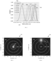
- FIGS. 7-10 provide experimental results for VBC fiber 200 (shown in FIGS. 2 and 3 ) and illustrate further a beam response to perturbation of VBC fiber 200 when a perturbation assembly 210 acts on VBC fiber 200 to bend the fiber.
- FIGS. 4-6 are simulations and FIGS. 7 - 10 are experimental results wherein a beam from a SM 1050 nm source was launched into an input fiber (not shown) with a 40 micron core diameter. The input fiber was spliced to first length of fiber 204.
- FIG. 4 is an example graph 400 illustrating the calculated profile of the lowest-order mode (LP 01 ) for a first length of fiber 204 for different fiber bend radii 402, wherein a perturbation assembly 210 involves bending VBC fiber 200.
- a perturbation assembly 210 involves bending VBC fiber 200.
- Higher-order modes (LP In ) also shift with bending.
- curve 406 for LP 01 is centered at or near the center of VBC fiber 200.
- curve 408 for LP 01 is shifted to a radial position of about 40 ⁇ m from the center 406 of VBC fiber 200.
- curve 410 for LP 01 is shifted to a radial position about 50 ⁇ m from the center 406 of VBC fiber 200.
- curve 412 for LP 01 is shifted to a radial position about 60 ⁇ m from the center 406 of VBC fiber 200.
- curve 414 for LP 01 is shifted to a radial position about 80 ⁇ m from the center 406 of VBC fiber 200.
- a curve 416 for LP 01 is shifted to a radial position about 85 ⁇ m from the center 406 of VBC fiber 200.
- the shape of the mode remains relatively constant (until it approaches the edge of the core), which is a specific property of a parabolic RIP. Although, this property may be desirable in some situations, it is not required for the VBC functionality, and other RIPs may be employed.
- second length of fiber 208 is to "trap" or confine the adjusted intensity distribution of the beam in a confinement region that is displaced from the center of the VBC fiber 200.
- the splice between fibers 204 and 208 is included in the bent region, thus the shifted mode profile will be preferentially launched into one of the ring-shaped confinement regions 218 and 220 or be distributed among the confinement regions.
- FIGS. 5 and 6 illustrate this effect.
- FIG. 5 illustrates an example of two-dimensional intensity distribution at junction 206 within second length of fiber 208 when VBC fiber 200 is nearly straight. A significant portion of LP 01 and LP In is within confinement region 216 of fiber 208.
- FIG. 6 illustrates the two-dimensional intensity distribution at junction 206 within second length of fiber 208 when VBC fiber 200 is bent with a radius chosen to preferentially excite confinement region 220 (the outermost confinement region) of second length of fiber 208. A significant portion of LP 01 and LP In is within confinement region 220 of fiber 208.
- confinement region 216 has a 100 micron diameter
- confinement region 218 is between 120 micron and 200 micron in diameter
- confinement region 220 is between 220 micron and 300 micron diameter.
- Confinement regions 216, 218, and 220 are separated by 10 ⁇ m thick rings of fluorosilicate, providing an NA of 0.22 for the confinement regions.
- Other inner and outer diameters for the confinement regions, thicknesses of the rings separating the confinement regions, NA values for the confinement regions, and numbers of confinement regions may be employed.
- VBC fiber 200 when VBC fiber 200 is straight, about 90% of the power is contained within the central confinement region 216, and about 100% of the power is contained within confinement regions 216 and 218.
- FIG. 6 when fiber 200 is bent to preferentially excite second ring confinement region 220, nearly 75% of the power is contained within confinement region 220, and more than 95% of the power is contained within confinement regions 218 and 220.
- These calculations include LP 01 and two higher-order modes, which are typical in some 2 - 4 kW fiber lasers.
- the bend radius determines the spatial overlap of the modal intensity distribution of the first length of fiber 204 with the different guiding confinement regions (216, 218, and 220) of the second length of fiber 208. Changing the bend radius can thus change the intensity distribution at the output of the second length of fiber 208, thereby changing the diameter or spot size of the beam, and thus changing its radiance and BPP value.
- This adjustment of the spot size may be accomplished in an all-fiber structure, involving no free-space optics and consequently may reduce or eliminate the disadvantages of free-space optics discussed above.
- Such adjustments can also be made with other perturbation assemblies that alter bend radius, bend length, fiber tension, temperature, or other perturbations discussed below.
- the output of the process fiber is imaged at or near the workpiece by the process head. Varying the intensity distribution as shown in FIGS. 5 and 6 thus enables variation of the beam profile at the workpiece in order to tune and/or optimize the process, as desired.
- Specific RIPs for the two fibers were assumed for the purpose of the above calculations, but other RIPs are possible, and claimed subject matter is not limited in this regard.
- FIGS. 7-10 depict experimental results (measured intensity distributions) to illustrate further output beams for various bend radii of VBC fiber 200 shown in FIG. 2 .
- FIG. 7 when VBC fiber 200 is straight, the beam is nearly completely confined to confinement region 216.
- the intensity distribution at the output shifts to the larger diameters of confinement regions 218 and 220 located farther away from confinement region 216-see e.g., this shift visible in FIGS. 8 - 10.
- FIG. 8 depicts the intensity distribution when the bend radius of VBC fiber 200 is chosen to shift the intensity distribution preferentially to confinement region 218.
- FIG. 9 depicts the experimental results when the bend radius is further reduced and chosen to shift the intensity distribution outward to confinement region 220 and confinement region 218.
- the beam is nearly a "donut mode," with most of the intensity in the outermost confinement region 220.
- the intensity distributions are nearly symmetric azimuthally because of scrambling within confinement regions as the beam propagates within the VBC fiber 200.
- the beam will typically scramble azimuthally as it propagates, various structures or perturbations (e.g., coils) could be included to facilitate this process.
- FIGS. 7-10 pertain to the particular fibers used in this experiment, and the details will vary depending on the specifics of the implementation.
- the spatial profile and divergence distribution of the output beam and their dependence on bend radius will depend on the specific RIPs employed, on the splice parameters, and on the characteristics of the laser source launched into the first fiber.
- Example RIPs for the first length of fiber include other graded-index profiles, step-index, pedestal designs (i.e., nested cores with progressively lower refractive indices with increasing distance from the center of the fiber), and designs with nested cores with the same refractive index value but with various NA values for the central core and the surrounding rings.
- Example RIPs for the second length of fiber in addition to the profile shown in FIG.
- VBC fiber 200 and other examples of a VBC fiber described herein are not restricted to use of two fibers. In some examples, implementation may include use of one fiber or more than two fibers.
- the fiber(s) may not be axially uniform; for example, they could include fiber Bragg gratings or long-period gratings, or the diameter could vary along the length of the fiber.
- the fibers do not have to be azimuthally symmetric, e.g., the core(s) could have square or polygonal shapes.
- Various fiber coatings may be employed, including high-index or index-matched coatings (which strip light at the glass-polymer interface) and low-index coatings (which guide light by total internal reflection at the glass-polymer interface). In some examples, multiple fiber coatings may be used on VBC fiber 200.
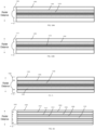
- FIGS. 11 - 16 illustrate cross-sectional views of examples of first lengths of fiber for enabling adjustment of beam characteristics in a VBC fiber responsive to perturbation of an optical beam propagating in the first lengths of fiber.
- Some examples of beam characteristics that may be adjusted in the first length of fiber are: beam diameter, beam divergence distribution, BPP, intensity distribution, luminance, M 2 factor, NA, optical intensity profile, optical power density profile, radial beam position, radiance, spot size, or the like, or any combination thereof.
- the first lengths of fiber depicted in FIGS. 11 - 16 and described below are merely examples and do not provide an exhaustive recitation of the variety of first lengths of fiber that may be utilized to enable adjustment of beam characteristics in a VBC fiber assembly.
- first length of fiber 1100 comprises a step-index profile 1102.
- FIG. 12 illustrates a first length of fiber 1200 comprising a "pedestal RIP" (i.e., a core comprising a step-index region surrounded by a larger step-index region) 1202.
- FIG. 13 illustrates a first length of fiber 1300 comprising a multiple-pedestal RIP 1302.
- FIG. 14A illustrates a first length of fiber 1400 comprising a graded-index profile 1418 surrounded by a down-doped region 1404.
- modes may shift radially outward in fiber 1400 (e.g., during bending of fiber 1400).
- Graded-index profile 1402 may be designed to promote maintenance or even compression of modal shape. This design may promote adjustment of a beam propagating in fiber 1400 to generate a beam having a beam intensity distribution concentrated in an outer perimeter of the fiber (i.e., in a portion of the fiber core that is displaced from the fiber axis).
- the intensity distribution of the adjusted beam may be trapped in the outermost confinement region, providing a donut shaped intensity distribution.
- a beam spot having a narrow outer confinement region may be useful to enable certain material processing actions.
- FIG. 14B illustrates a first length of fiber 1406 comprising a graded-index profile 1414 surrounded by a down-doped region 1408 similar to that of fiber 1400.
- fiber 1406 includes a divergence structure 1410 (a lower-index region) as can be seen in profile 1412.
- the divergence structure 1410 is an area of material with a lower refractive index than that of the surrounding core.
- the amount of increased divergence depends on the amount of spatial overlap of the beam with the divergence structure 1410 and the magnitude of the index difference between the divergence structure 1410 and the core material.
- Divergence structure 1410 can have a variety of shapes, depending on the input divergence distribution and desired output divergence distribution. In an example, divergence structure 1410 has a triangular or graded index shape.
- FIG. 15 illustrates a first length of fiber 1500 comprising a parabolic-index central region 1502 surrounded by a constant-index region 1504. Between the constant-index region 1504 and the parabolic-index central region 1502 is a lower-index annular layer (or lower-index ring or annulus) 1506 surrounding the parabolic-index central region 1502.
- the lower-index annulus 1506 helps guide a beam propagating in fiber 1500. When the propagating beam is perturbed, modes shift radially outward in fiber 1500 (e.g., during bending of fiber 1500). As one or more modes shift radially outward, parabolic-index region 1502 promotes retention of modal shape.
- this fiber design works with a confinement fiber having a central step-index core and a single annular core.
- the parabolic-index portion 1502 of the RIP 1510 overlaps with the central step-index core of the confinement fiber.
- the constant-index portion 1504 overlaps with the annular core of the confinement fiber.
- the constant-index portion 1504 of the first fiber is intended to make it easier to move the beam into overlap with the annular core by bending. This fiber design also works with other designs of the confinement fiber.
- FIG. 16 illustrates a first length of fiber 1600 comprising guiding regions 1604, 1606, 1608, and 1616 bounded by lower-index layers 1610, 1612, and 1614 where the indexes of the lower-index layers 1610, 1612, and 1614 are stepped or, more generally, do not all have the same value.
- the stepped-index layers may serve to bound the beam intensity to certain guiding regions (1604, 1606, 1608, and 1616) when the perturbation assembly 210 (see FIG. 2 ) acts on the fiber 1600.
- adjusted beam light may be trapped in the guiding regions over a range of perturbation actions (such as over a range of bend radii, a range of bend lengths, a range of micro-bending pressures, and/or a range of acousto-optical signals), allowing for a certain degree of perturbation tolerance before a beam intensity distribution is shifted to a more distant radial position in fiber 1600.
- variation in beam characteristics may be controlled in a step-wise fashion.
- the radial widths of the guiding regions 1604, 1606, 1608, and 1616 may be adjusted to achieve a desired ring width, as may be required by an application.
- a guiding region can have a thicker radial width to facilitate trapping of a larger fraction of the incoming beam profile if desired. Region 1606 is an example of such a design.
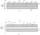
- FIGS. 17 - 21 depict examples of fibers configured to enable maintenance and/or confinement of adjusted beam characteristics in the second length of fiber (e.g., fiber 208).
- These fiber designs are referred to as "ring-shaped confinement fibers" because they contain a central core surrounded by annular or ring-shaped cores.
- These designs are merely examples and not an exhaustive recitation of the variety of fiber RIPs that may be used to enable maintenance and/or confinement of adjusted beam characteristics within a fiber.
- claimed subject matter is not limited to the examples provided herein.
- any of the first lengths of fiber described above with respect to FIGS. 11 - 16 may be combined with any of the second length of fiber described FIGS. 17 - 21 .
- FIG. 17 illustrates a cross-sectional view of an example second length of fiber for maintaining and/or confining adjusted beam characteristics in a VBC fiber assembly.
- the second length of fiber 1700 may maintain at least a portion of the beam characteristics adjusted in response to perturbation in the first length of fiber within one or more of confinement regions 1704, 1706, and/or 1708.
- Fiber 1700 has a RIP 1702.
- Each of confinement regions 1704, 1706, and/or 1708 is bounded by a lower index layer 1710 and/or 1712.
- This design enables second length of fiber 1700 to maintain the adjusted beam characteristics.
- a beam output by fiber 1700 will substantially maintain the received adjusted beam as modified in the first length of fiber giving the output beam adjusted beam characteristics, which may be customized to a processing task or other application.
- FIG. 18 depicts a cross-sectional view of an example second length of fiber 1800 for maintaining and/or confining beam characteristics adjusted in response to perturbation in the first length of fiber in a VBC fiber assembly.
- Fiber 1800 has a RIP 1802.
- confinement regions 1808, 1810, and/or 1812 have different thicknesses from the thicknesses of confinement regions 1704, 1706, and 1708.
- Each of confinement regions 1808, 1810, and/or 1812 is bounded by a lower index layer 1804 and/or 1806. Varying the thicknesses of the confinement regions (and/or barrier regions) enables tailoring or optimization of a confined adjusted radiance profile by selecting particular radial positions within which to confine an adjusted beam.
- FIG. 19 depicts a cross-sectional view of an example second length of fiber 1900 having a RIP 1902 for maintaining and/or confining an adjusted beam in a VBC fiber assembly configured to provide variable beam characteristics.
- the number and thicknesses of confinement regions 1904, 1906, 1908, and 1910 are different from those of fiber 1700 and 1800; and the barrier layers 1912, 1914, and 1916 are of varied thicknesses as well.
- confinement regions 1904, 1906, 1908, and 1910 have different indexes of refraction; and barrier layers 1912, 1914, and 1916 have different indexes of refraction as well.
- This design may further enable a more granular or optimized tailoring of the confinement and/or maintenance of an adjusted beam radiance to particular radial locations within fiber 1900.
- the modified beam characteristics of the beam (having an adjusted intensity distribution, radial position, and/or divergence angle, or the like, or a combination thereof) is confined within a specific radius by one or more of confinement regions 1904, 1906, 1908, and/or 1910 of second length of fiber 1900.
- the divergence angle of a beam may be conserved or adjusted and then conserved in the second length of fiber.
- claimed subject matter is not limited to the examples provided herein.
- FIG. 20 depicts a cross-sectional view of an example second length of fiber 2000 having a RIP 2002 for modifying, maintaining, and/or confining beam characteristics adjusted in response to perturbation in the first length of fiber.
- second length of fiber 2000 is similar to the previously described second lengths of fiber and forms a portion of the VBC fiber assembly for delivering variable beam characteristics as discussed above.
- Second length of fiber 2000 also has a divergence structure 2014 situated within the confinement region 2006.
- the divergence structure 2014 is an area of material with a lower refractive index than that of the surrounding confinement region.
- divergence structure 2014 As the beam is launched into second length of fiber 2000, refraction from divergence structure 2014 causes the beam divergence to increase in second length of fiber 2000.
- the amount of increased divergence depends on the amount of spatial overlap of the beam with the divergence structure 2014 and the magnitude of the index difference between the divergence structure 2014 and the core material.
- the divergence distribution may be varied.
- the adjusted divergence of the beam is conserved in fiber 2000, which is configured to deliver the adjusted beam to the process head, another optical system (e.g., fiber-to-fiber coupler or fiber-to-fiber switch), the workpiece, or the like, or a combination thereof.
- divergence structure 2014 may have an index dip of about 10 -5 - 3 ⁇ 10 -2 with respect to the surrounding material. Other values of the index dip may be employed within the scope of this disclosure, and claimed subject matter is not so limited.
- FIG. 21 depicts a cross-sectional view of an example second length of fiber 2100 having a RIP 2102 for modifying, maintaining, and/or confining beam characteristics adjusted in response to perturbation in the first length of fiber.
- Second length of fiber 2100 forms a portion of a VBC fiber assembly for delivering a beam having variable characteristics.
- Second length of fiber 2100 also has a plurality of divergence structures 2114 and 2118.
- the divergence structures 2114 and 2118 are areas of graded lower index material.
- divergence structures 2114 and 2118 As the beam is launched from the first length fiber into second length of fiber 2100, refraction from divergence structures 2114 and 2118 causes the beam divergence to increase.
- the amount of increased divergence depends on the amount of spatial overlap of the beam with the divergence structure and the magnitude of the index difference between the divergence structure 2114 and/or 2118 and the surrounding core material of confinement regions 2106 and 2104 respectively.
- the divergence distribution may be varied.
- the design shown in FIG. 21 allows the intensity distribution and the divergence distribution to be varied somewhat independently by selecting both a particular confinement region and the divergence distribution within that confinement region (because each confinement region may include a divergence structure).
- the adjusted divergence of the beam is conserved in fiber 2100, which is configured to deliver the adjusted beam to the process head, another optical system, or the workpiece.
- Forming the divergence structures 2114 and 2118 with a graded or non-constant index enables tuning of the divergence profile of the beam propagating in fiber 2100.
- An adjusted beam characteristic such as a radiance profile and/or divergence profile may be conserved as it is delivered to a process head by the second fiber.
- an adjusted beam characteristic such as a radiance profile and/or divergence profile may be conserved or further adjusted as it is routed by the second fiber through a fiber-to-fiber coupler (FFC) and/or fiber-to-fiber switch (FFS) and to a process fiber, which delivers the beam to the process head or the workpiece.
- FFC fiber-to-fiber coupler
- FFS fiber-to-fiber switch
- FIGS. 26 - 28 are cross-sectional views illustrating examples of fibers and fiber RIPs configured to enable maintenance and/or confinement of adjusted beam characteristics of a beam propagating in an azimuthally asymmetric second length of fiber, wherein the beam characteristics are adjusted responsive to perturbation of a first length of fiber coupled to the second length of fiber and/or perturbation of the beam by a perturbation device 110.
- These azimuthally asymmetric designs are merely examples and are not an exhaustive recitation of the variety of fiber RIPs that may be used to enable maintenance and/or confinement of adjusted beam characteristics within an azimuthally asymmetric fiber.
- claimed subject matter is not limited to the examples provided herein.
- any of a variety of first lengths of fiber e.g., like those described above
- any azimuthally asymmetric second length of fiber e.g., like those described in FIGS. 26 - 28 ).
- FIG. 26 illustrates RIPs at various azimuthal angles of a cross-section through an elliptical fiber 2600.
- fiber 2600 At a first azimuthal angle 2602, fiber 2600 has a first RIP 2604.
- fiber 2600 At a second azimuthal angle 2606 that is rotated 45° from first azimuthal angle 2602, fiber 2600 has a second RIP 2608.
- fiber 2600 At a third azimuthal angle 2610 that is rotated another 45° from second azimuthal angle 2606, fiber 2600 has a third RIP 2612.
- First, second, and third RIPs 2604, 2608, and 2612 are all different.
- FIG. 27 illustrates RIPs at various azimuthal angles of a cross-section through a multicore fiber 2700.
- fiber 2700 At a first azimuthal angle 2702, fiber 2700 has a first RIP 2704.
- fiber 2700 At a second azimuthal angle 2706, fiber 2700 has a second RIP 2708.
- First and second RIPs 2704 and 2708 are different.
- perturbation device 110 may act in multiple planes in order to launch the adjusted beam into different regions of an azimuthally asymmetric second fiber.
- FIG. 28 illustrates RIPs at various azimuthal angles of a cross-section through a fiber 2800 having at least one crescent shaped core. In some cases, the corners of the crescent may be rounded, flattened, or otherwise shaped, which may minimize optical loss.
- fiber 2800 At a first azimuthal angle 2802, fiber 2800 has a first RIP 2804.
- fiber 2800 At a second azimuthal angle 2806, fiber 2800 has a second RIP 2808.
- First and second RIPs 2804 and 2808 are different.
- FIG. 22A illustrates an example of a laser system 2200 including a VBC fiber assembly 2202 configured to provide variable beam characteristics.
- VBC fiber assembly 2202 comprises a first length of fiber 104, a second length of fiber 108, and a perturbation device 110.
- VBC fiber assembly 2202 is disposed between feeding fiber 2212 (i.e., the output fiber from the laser source) and VBC delivery fiber 2240.
- VBC delivery fiber 2240 may comprise second length of fiber 108 or an extension of second length of fiber 108 that modifies, maintains, and/or confines adjusted beam characteristics.
- Beam 2210 is coupled into VBC fiber assembly 2202 via feeding fiber 2212.
- Fiber assembly 2202 is configured to vary the characteristics of beam 2210 in accordance with the various examples described above.
- the output of fiber assembly 2202 is adjusted beam 2214, which is coupled into VBC delivery fiber 2240.
- VBC delivery fiber 2240 delivers adjusted beam 2214 to a free-space optics assembly 2208, which then couples beam 2214 into a process fiber 2204.
- Adjusted beam 2214 is then delivered to process head 2206 by process fiber 2204.
- the process head can include guided wave optics (such as fibers and fiber coupler), free space optics (such as lenses, mirrors, optical filters, diffraction gratings), and/or beam scan assemblies (such as galvanometer scanners, polygonal mirror scanners, or other scanning systems) that are used to shape the beam 2214 and deliver the shaped beam to a workpiece.
- one or more of the free-space optics of assembly 2208 may be disposed in an FFC or other beam coupler 2216 to perform a variety of optical manipulations of an adjusted beam 2214 (represented in FIG. 22A with different dashing from that of beam 2210).
- free-space optics assembly 2208 may preserve the adjusted beam characteristics of beam 2214.
- Process fiber 2204 may have the same RIP as VBC delivery fiber 2240.
- the adjusted beam characteristics of adjusted beam 2214 may be preserved all the way to process head 2206.
- Process fiber 2204 may comprise a RIP similar to any of the second lengths of fiber described above, including confinement regions.
- free-space optics assembly 2208 may change the adjusted beam characteristics of beam 2214 by, for example, increasing or decreasing the divergence and/or the spot size of beam 2214 (e.g., by magnifying or demagnifying beam 2214) and/or otherwise further modifying adjusted beam 2214.
- process fiber 2204 may have a different RIP than VBC delivery fiber 2240. Accordingly, the RIP of process fiber 2204 may be selected to preserve additional adjustment of adjusted beam 2214 made by the free-space optics of assembly 2208 to generate a twice adjusted beam 2224 (represented in FIG. 22B with different dashing from that of beam 2214).
- FIG. 23 illustrates an example of a laser system 2300 including VBC fiber assembly 2302 disposed between a feeding fiber 2312 and a VBC delivery fiber 2340.
- a beam 2310 is coupled into VBC fiber assembly 2302 via feeding fiber 2312.
- Fiber assembly 2302 includes a first length of fiber 104, a second length of fiber 108, and a perturbation device 110 and is configured to vary characteristics of beam 2310 in accordance with the various examples described above.
- Fiber assembly 2302 generates an adjusted beam 2314 output by VBC delivery fiber 2340.
- VBC delivery fiber 2340 comprises a second length of fiber 108 of fiber for modifying, maintaining, and/or confining adjusted beam characteristics in a fiber assembly 2302 in accordance with the various examples described above (see FIGS.
- VBC delivery fiber 2340 couples adjusted beam 2314 into a beam switch (FFS) 2332, which then couples its various output beams to one or more of multiple process fibers 2304, 2320, and 2322.
- FFS beam switch
- Process fibers 2304, 2320, and 2322 deliver adjusted beams 2314, 2328, and 2330 to respective process heads 2306, 2324, and 2326.
- beam switch 2332 includes one or more sets of free-space optics 2308, 2316, and 2318 configured to perform a variety of optical manipulations of adjusted beam 2314.
- Free-space optics 2308, 2316, and 2318 may preserve or vary adjusted beam characteristics of beam 2314.
- adjusted beam 2314 may be maintained by the free-space optics or adjusted further.
- Process fibers 2304, 2320, and 2322 may have the same or a different RIP as that of VBC delivery fiber 2340, depending on whether it is desirable to preserve or further modify a beam passing from the free-space optics assemblies 2308, 2316, and 2318 to respective process fibers 2304, 2320, and 2322.
- one or more beam portions of beam 2310 are coupled to a workpiece without adjustment, or different beam portions are coupled to respective VBC fiber assemblies so that beam portions associated with a plurality of beam characteristics can be provided for simultaneous workpiece processing.
- beam 2310 can be switched to one or more of a set of VBC fiber assemblies.
- Routing adjusted beam 2314 through any of free-space optics assemblies 2308, 2316, and 2318 enables delivery of a variety of additionally adjusted beams to process heads 2206, 2324, and 2326. Therefore, laser system 2300 provides additional degrees of freedom for varying the characteristics of a beam, as well as switching the beam between process heads ("time sharing") and/or delivering the beam to multiple process heads simultaneously (“power sharing").
- free-space optics in beam switch 2332 may direct adjusted beam 2314 to free-space optics assembly 2316 configured to preserve the adjusted characteristics of beam 2314.
- Process fiber 2304 may have the same RIP as that of VBC delivery fiber 2340. Thus, the beam delivered to process head 2306 will be a preserved adjusted beam 2314.
- beam switch 2332 may direct adjusted beam 2314 to free-space optics assembly 2318 configured to preserve the adjusted characteristics of adjusted beam 2314.
- Process fiber 2320 may have a different RIP from that of VBC delivery fiber 2340 and may be configured with divergence altering structures as described with respect to FIGS. 20 and 21 to provide additional adjustments to the divergence distribution of beam 2314.
- the beam delivered to process head 2324 will be a twice adjusted beam 2328 having a different beam divergence profile from that of adjusted beam 2314.
- Process fibers 2304, 2320, and/or 2322 may comprise a RIP similar to any of the second lengths of fiber described above, including confinement regions or a wide variety of other RIPs, and claimed subject matter is not limited in this regard.
- free-space optics switch 2332 may direct adjusted beam 2314 to free-space optics assembly 2308 configured to change the beam characteristics of adjusted beam 2314.
- Process fiber 2322 may have a different RIP from that of VBC delivery fiber 2340 and may be configured to preserve (or alternatively further modify) the new further adjusted characteristics of beam 2314.
- the beam delivered to process head 2326 will be a twice adjusted beam 2330 having different beam characteristics (due to the adjusted divergence profile and/or intensity profile) from those of adjusted beam 2314.
- the optics in the FFC or FFS may adjust the spatial profile and/or divergence profile by magnifying or demagnifying the beam 2214 before launching into the process fiber. They may also adjust the spatial profile and/or divergence profile via other optical transformations. They may also adjust the launch position into the process fiber. These methods may be used alone or in combination.
- FIGS. 22A, 22B, and 23 merely provide examples of combinations of adjustments to beam characteristics using free-space optics and various combinations of fiber RIPs to preserve or modify adjusted beams 2214 and 2314.
- the examples provided above are not exhaustive and are meant for illustrative purposes only. Thus, claimed subject matter is not limited in this regard.
- FIG. 24 illustrates various examples of perturbation devices, assemblies or methods (for simplicity referred to collectively herein as "perturbation device 110") for perturbing a VBC fiber 200 and/or an optical beam propagating in VBC fiber 200 according to various examples provided herein.
- Perturbation device 110 may be any of a variety of devices, methods, and/or assemblies configured to enable adjustment of beam characteristics of a beam propagating in VBC fiber 200.
- Some examples of various states of perturbation that may be applied to VBC fiber 200 include, but are not limited to, amount or direction of bending, lateral mechanical stress, acoustic wave oscillation-induced mechanical pressure, temperature variation, piezo-electric transducer displacement, and varying periodicity or amplitude of refractive grating.
- perturbation device 110 may be a mandrel 2402, a micro-bend 2404 in the VBC fiber, flexible tubing 2406, an acousto-optic transducer 2408, a thermal device 2410, a piezo-electric device 2412, a grating 2414, a clamp 2416 (or other fastener), or the like, or any combination thereof.
- perturbation devices 100 may be a mandrel 2402, a micro-bend 2404 in the VBC fiber, flexible tubing 2406, an acousto-optic transducer 2408, a thermal device 2410, a piezo-electric device 2412, a grating 2414, a clamp 2416 (or other fastener), or the like, or any combination thereof.
- Mandrel 2402 may be used to perturb VBC fiber 200 by providing a form about which VBC fiber 200 may be bent. As discussed above, reducing the bend radius of VBC fiber 200 moves the intensity distribution of the beam radially outward.
- mandrel 2402 may be stepped or conically shaped to provide discrete bend radii levels.
- mandrel 2402 may comprise a cone shape without steps to provide continuous bend radii for more granular control of the bend radius.
- the radius of curvature of mandrel 2402 may be constant (e.g., a cylindrical form) or non-constant (e.g., an oval-shaped form).
- VBC fiber 200 and mandrel 2402 may be configured to change the intensity distribution within the first fiber predictably (e.g., in proportion to the length over which the fiber is bent and/or the bend radius).
- Rollers 250 may move up and down along a track 2442 on a platform 2434 to change the bend radius of VBC fiber 200.
- Clamps 2416 may be used to guide and control the bending of VBC fiber 200 with or without a mandrel 2402. Clamps 2416 may move up and down along a track 2442 or a platform 2446. Clamps 2416 may also swivel to change bend radius, tension, or direction of VBC fiber 200. A controller 2448 may control the movement of clamps 2416.
- perturbation device 110 may be flexible tubing 2406 and may guide bending of VBC fiber 200 with or without a mandrel 2402.
- Flexible tubing 2406 may encase VBC fiber 200.
- Tubing 2406 may be made of a variety of materials and may be manipulated using piezoelectric transducers controlled by a controller 2444. In another example, clamps or other fasteners may be used to move flexible tubing 2406.
- Micro-bend 2404 in VBC fiber is a local perturbation caused by lateral mechanical stress on the fiber. Micro-bending can cause mode coupling and/or transitions from one confinement region to another confinement region within a fiber, resulting in varied beam characteristics of the beam propagating in a VBC fiber 200.
- Mechanical stress may be applied by an actuator 2436 that is controlled by controller 2440.
- this is merely an example of a method for inducing mechanical stress in fiber 200 and claimed subject matter is not limited in this regard.
- Acousto-optic transducer (AOT) 2408 may be used to induce perturbation of a beam propagating in the VBC fiber using an acoustic wave.
- the perturbation is caused by the modification of the refractive index of the fiber by the oscillating mechanical pressure of an acoustic wave.
- the period and strength of the acoustic wave are related to the acoustic wave frequency and amplitude, allowing dynamic control of the acoustic perturbation.
- a perturbation assembly 110 including AOT 2408 may be configured to vary the beam characteristics of a beam propagating in the fiber.
- a piezo-electric transducer 2418 may create the acoustic wave and may be controlled by a controller or driver 2420.
- the acoustic wave induced in AOT 2408 may be modulated to change and/or control the beam characteristics of the optical beam in VBC 200 in real-time.
- this is merely an example of a method for creating and controlling an AOT 2408, and claimed subject matter is not limited in this regard.
- Thermal device 2410 may be used to induce perturbation of a beam propagating in VBC fiber using heat.
- the perturbation is caused by the modification of the RIP of the fiber induced by heat.
- Perturbation may be dynamically controlled by controlling an amount of heat transferred to the fiber and the length over which the heat is applied.
- a perturbation assembly 110 including thermal device 2410 may be configured to vary a range of beam characteristics.
- Thermal device 2410 may be controlled by a controller 2450.
- Piezo-electric transducer 2412 may be used to induce perturbation of a beam propagating in a VBC fiber using piezoelectric action.
- the perturbation is caused by the modification of the RIP of the fiber induced by a piezoelectric material attached to the fiber.
- the piezoelectric material in the form of a jacket around the bare fiber may apply tension or compression to the fiber, modifying its refractive index via the resulting changes in density.
- Perturbation may be dynamically controlled by controlling a voltage to the piezo-electric device 2412.
- a perturbation assembly 110 including piezo-electric transducer 2412 may be configured to vary the beam characteristics over a particular range.
- piezo-electric transducer 2412 may be configured to displace VBC fiber 200 in a variety of directions (e.g., axially, radially, and/or laterally) depending on a variety of factors, including how the piezo-electric transducer 2412 is attached to VBC fiber 200, the direction of the polarization of the piezo-electric materials, the applied voltage, etc. Additionally, bending of VBC fiber 200 is possible using the piezo-electric transducer 2412. For example, driving a length of piezo-electric material having multiple segments comprising opposing electrodes can cause a piezoelectric transducer 2412 to bend in a lateral direction.
- Voltage applied to piezoelectric transducer 2412 by an electrode 2424 may be controlled by a controller 2422 to control displacement of VBC fiber 200.
- Displacement may be modulated to change and/or control the beam characteristics of the optical beam in VBC 200 in real-time.
- this is merely an example of a method of controlling displacement of a VBC fiber 200 using a piezo-electric transducer 2412 and claimed subject matter is not limited in this regard.
- Gratings 2414 may be used to induce perturbation of a beam propagating in a VBC fiber 200.
- a grating 2414 can be written into a fiber by inscribing a periodic variation of the refractive index into the core.
- Gratings 2414 such as fiber Bragg gratings can operate as optical filters or as reflectors.
- a long-period grating can induce transitions among co-propagating fiber modes. The radiance, intensity profile, and/or divergence profile of a beam comprised of one or more modes can thus be adjusted using a long-period grating to couple one or more of the original modes to one or more different modes having different radiance and/or divergence profiles.
- VBC fiber 200 having gratings 2414 may be coupled to a stage 2426.
- Stage 2426 may be configured to execute any of a variety of functions and may be controlled by a controller 2428.
- stage 2426 may be coupled to VBC fiber 200 with fasteners 2430 and may be configured to stretch and/or bend VBC fiber 200 using fasteners 2430 for leverage.
- Stage 2426 may have an embedded thermal device and may change the temperature of VBC fiber 200.
- FIG. 25 illustrates an example process 2500 for adjusting and/or maintaining beam characteristics within a fiber without the use of free-space optics to adjust the beam characteristics.
- a first length of fiber and/or an optical beam are perturbed to adjust one or more optical beam characteristics.
- Process 2500 moves to block 2504, where the optical beam is launched into a second length of fiber.
- Process 2500 moves to block 2506, where the optical beam having the adjusted beam characteristics is propagated in the second length of fiber.
- Process 2500 moves to block 2508, where at least a portion of the one or more beam characteristics of the optical beam are maintained within one or more confinement regions of the second length of fiber.
- the first and second lengths of fiber may be comprised of the same fiber, or they may be different fibers.
- the present inventors have developed techniques for using even relatively long lengths of delivery fiber (also called a feeding fiber) to selectively deliver SM and MM outputs, yet without the onset of non-linear effects. More generally, these techniques accommodate changes in optical power of a beam by dynamically perturbing a beam, which controls (among other things) its spot size incident upon a cross-sectional area of a set of confinement regions in the delivery fiber through which the beam propagates.
- the perturbation can be thought of as essentially simulating a manipulation of the effective (i.e. active) size of the area of the delivery fiber so as to control optical power density (i.e., optical power divided by the active size of the area).
- the optical power may also be increased (i.e., more optical intensity is distributed over a larger area of confinement regions).
- the optical power may also be decreased (i.e., less optical intensity is distributed over a smaller area of confinement regions) to adjust optical power density and thereby avoid non-linear effects.
- the optical power density is controlled by manipulating the active size of the area
- power is also coordinated such that it remains below a calculated threshold that accounts for the length of the delivery fiber and the current active size of the area.
- the calculated threshold represents a maximum power beyond which non-linear effects would otherwise appear.
- the threshold is increased.
- the threshold is decreased.
- a process engineer may specify a desired spot size (or BPP) that is suitable for generating a printed feature sized according to the desired spot size.
- a large feature would use a large spot size, and vice versa.
- fluence would ideally remain uniform and constant. Fluence is a relevant process parameter in this example because the printing material has an optimal melt temperature that commands a fairly consistent, uniform power density irrespective of spot size.
- embodiments described in this discloser deliver variable spot sizes capable of providing the proper fluence.
- embodiments described in this disclosure establish an upper power threshold to which a laser source may be driven.
- This threshold may not be directly communicated to the 3D process engineer, but it would impact the spot sizes available to the engineer at certain values of fluence.
- users are able to employ relatively long lengths for either MM output (at higher total power) or SM output (at lower total power).
- the threshold also changes based on the active size of the area of the confinement regions and on the length of the delivery fiber.
- FIG. 29 shows an optical power control system 2900 implemented with an optical beam delivery device 2902 in the form of a VBC fiber 2906, which is constructed in accordance with the disclosed paradigm represented by example VBC fiber 100 (see e.g., FIG. 1 for additional details). For conciseness, some previously described details of FIG. 1 are further simplified and, therefore, not reproduced in FIG. 29 . Note also that subscripts "A,” “B,” “C,” and “D” represent different selectable configurations of optical power control system 2900, which are explained in the following paragraphs.
- a laser source 2910 emits a variable-power optical beam 102 ( FIG. 1 ) propagating in a first length of fiber 2912, which corresponds to first length of fiber 104 ( FIG. 1 ).
- a first power configuration 2918 A -also referred to generally as optical power 2918x, where "X" corresponds to a particular power-output configuration of laser source 2910-variable-power optical beam 102 has a relatively low amount of optical power incident on VBC fiber 2906.
- second, third, and fourth power configurations 2918 B - 2918 D optical power is successively increased.
- Perturbation device 110 operating in combination with, and applying different states (e.g., different amounts or directions) of perturbation to, VBC fiber 2906 directs the fiber mode to different corresponding confinement regions of a second length of fiber 2920, which corresponds to second length of fiber 108 ( FIG. 1 ).
- a controller 2930 is operatively coupled to VBC fiber 2906 via perturbation device 110. Controller 2930 thereby enables optical power control system 2900 to selectively move the fiber mode, i.e., an intensity distribution, of optical beam 102 to different areas at an input of second length of fiber 2920.
- Example types of information to which controller 2930 may monitor and respond to in connection with its control over perturbation device 110 and (optionally) laser source 2910 are set forth in later paragraphs.
- Controller 2930 which is responsive to such information indicating changes (i.e., actually measured by a meter or indicated changes yet to take effect) in optical power of the optical beam, provides control signals to perturbation device 110.
- perturbation device 110 applies to VBC fiber 2906 a perturbation state (e.g., a controlled amount or direction of bend) that shifts the fiber mode to a different area among the confinement regions and thereby provides a means of controlling, at an output of second length of fiber 2920, optical power density.
- a perturbation state e.g., a controlled amount or direction of bend
- controller 2930 signals perturbation device 110 to apply a first state of perturbation to VBC fiber 2906 and thereby establish a confined portion 2940 A of an adjusted optical beam (not shown in FIG. 29 , but for an example see adjusted beam 226 of FIG. 5 ).
- Confined portion 2940 A shown in an end view at an output end of second length of fiber 2920, has a corresponding optical power density 2946 A and is provided to a process head 2950 for carrying out a laser processing task one or more workpieces 2960 A - 2960 D .
- confined portion 2940 A results from no perturbation.
- confined portion 2940 A occupies a central core and provides an SM output optimized for cutting efficiency while avoiding SRS or other non-linear effects that would otherwise occur at higher powers.
- SM lasers have very high brightness because the mode field diameter is small (about 14 microns) with low divergence (about .06 NA). By delivering relatively high optical power to a small area, SM lasers are useful for metal additive manufacturing employed in the manufacture of, e.g., very large-scale parts (e.g., components for aviation).
- long delivery fibers are useful in additive laser-processing tools (e.g., laser-assisted deposition tools) having a movable scanning head that translates on a gantry in two dimensions.
- additive laser-processing tools e.g., laser-assisted deposition tools
- Other laser applications and processes entailing integration with industrial tools are also facilitated by relatively long delivery fiber lengths (greater than five meters).
- tools for cutting large-area sheet metal parts also use long service lengths of delivery fiber coupled to a cutting head that moves on a 2D gantry. But for a given fiber core diameter, the amount of optical power of an SM laser is inversely proportional to useful delivery fiber length.
- SM laser output may be useful for some portions of the processing (e.g., adding to and cutting from metal parts), other stages of processing need not use SM. Instead, higher power multi-mode (MM) beams may be used. Nevertheless, for reasons mentioned previously, delivery fiber length is sometimes limited by processes using SM beams.
- MM multi-mode
- controller 2930 signals perturbation device 110 to apply a second state of perturbation, different from the first state, to VBC fiber 2906 and thereby establish a confined portion 2940 B .
- Confined portion 2940 B has corresponding optical power density 2946 B , which may be the same as or different than optical power density 2946 A .
- power densities 2946 A - 2946 D remain roughly equal to one another as optical powers 2918 A - 2918 D change. This is so because cross-sectional areas of confined portions 2940 A - 2940 D increase proportionally with changes in optical powers 2918 A - 2918 D .
- flat-top beam shapes are represented by confined portions 2940 A - 2940 D
- actual beam shapes may be varied and need not have a flat-top intensity distribution implied by FIG. 29 .
- Confined portions may also provide other beam shapes and corresponding intensity distributions shown in, for example, FIGS. 7 - 10 .
- controller 2930 in some embodiments it comprises a computer workstation having input-output (I/O) devices suitable for establishing a signal interface with perturbation device 110 and other devices so as to receive optical power information and generate signals controlling states of perturbation in accordance with changes in optical power indicated through, e.g., user input.
- I/O input-output
- controller 2930 may include a central processing unit (CPU), field-programmable gate array (FPGA), or other control devices suitable for performing logic operations.
- Controller 2930 may also include a non-transitory machine-readable storage medium storing instructions thereon that, when executed, cause controller 2930 to perform any methods or operations described in this disclosure.
- Different power densities 2946 A - 2946 D are controlled based on different material properties, different desired beam shapes, sizes of various confinement regions, or on combinations of these factors. Examples of some different control factors and schemes are represented by broken lines extending from and leading to controller 2930. In general, these broken lines simply represent types of information to which controller 2930 is responsive. For example, according to some embodiments, a change from one perturbation state to another state is configured indirectly, e.g., in response to a selected change 2980 in either a type of material to be processed or an indirectly related calibration setting for material of the same or different type than the one that was previously processed.
- a change from one perturbation state to another state is configured directly, e.g., by a direct selection 2990 of a desired beam shape or power configuration (i.e., potentially irrespective of material).
- a user may select a beam shape or power configuration through a selection interface 2996 provided by, e.g., controller 2930 or laser source 2910, so as to contemporaneously change both the power configuration and the perturbation state.
- the change may also be made fully or partly autonomously.
- FIG. 29 represents power configurations 2918 A - 2918 D by showing a power meter.
- a threshold line labeled with "Threshold(2998x,L)," where L represents lengths of the delivery fiber and 2998x represents active sizes of the area through which the confined portion of the adjusted optical beam propagates.
- the threshold lines represent a maximum power that may propagate as a function of a current active size area and current length of a delivery fiber.
- the threshold is about one kilowatt (kW) when the central core is around 14 microns in diameter and 10 meters (m) in length or 700 watts (W) for the same core size and 20 meters (m) in length.
- These thresholds increase, however, as the sizes of the area increase (e.g., in the "B” - “D” configurations) that employ annular confinement regions in additional to the central core.
Landscapes
- Physics & Mathematics (AREA)
- Optics & Photonics (AREA)
- Engineering & Computer Science (AREA)
- General Physics & Mathematics (AREA)
- Mechanical Engineering (AREA)
- Chemical & Material Sciences (AREA)
- Manufacturing & Machinery (AREA)
- Materials Engineering (AREA)
- Plasma & Fusion (AREA)
- Nonlinear Science (AREA)
- Automation & Control Theory (AREA)
- Electromagnetism (AREA)
- Health & Medical Sciences (AREA)
- Toxicology (AREA)
- Crystallography & Structural Chemistry (AREA)
- Condensed Matter Physics & Semiconductors (AREA)
- Lasers (AREA)
- Optical Couplings Of Light Guides (AREA)
- Laser Beam Processing (AREA)
- Optical Modulation, Optical Deflection, Nonlinear Optics, Optical Demodulation, Optical Logic Elements (AREA)
- Optical Fibers, Optical Fiber Cores, And Optical Fiber Bundles (AREA)
- Mechanical Light Control Or Optical Switches (AREA)
- Light Guides In General And Applications Therefor (AREA)
Claims (15)
- Dispositif de délivrance de faisceau optique (2902) configuré pour faciliter une coordination de différents états d'une perturbation appliquée avec des changements de puissance optique d'un faisceau optique (102) généré par une source laser (2910), le dispositif de délivrance de faisceau optique (2902) comprenant :une première longueur de fibre (104 ; 204 ; 1100 ; 1300 ; 1400 ; 1406 ; 1500 ; 1500 ; 1600 ; 2912) présentant un premier profil d'indice de réfraction (RIP) (212 ; 1102 ; 1202 ; 1302; 1402; 1412 ; 1504; 1602), le premier RIP permettant, en réponse à une perturbation appliquée, une modification du faisceau optique pour former un faisceau optique ajusté, le faisceau optique ajusté définissant, à une extrémité de sortie de la première longueur de fibre, différentes distributions d'intensité basées sur différents états de la perturbation appliquée ; etune seconde longueur de fibre (108 ; 208 ; 1700 ; 1800 ; 1900 ; 2000 ; 2100 ; 2920) présentant une extrémité d'entrée couplée à l'extrémité de sortie de la première longueur de fibre, la seconde longueur de fibre étant pourvue de multiples régions de confinement (216, 218, 220; 1704, 1706, 1708 ; 1808, 1810, 1812; 1904, 1906, 1908, 1910 ; 2004, 2006, 2008 ; 2104, 2106, 2108) définissant un second RIP (1702 ; 1802; 1902 ; 2002 ; 2102) qui est différent du premier RIP, les multiples régions de confinement étant agencées pour confiner au moins une portion du faisceau optique ajusté, la portion confinée (2940A, 2940B, 2940C, 2940D) correspondant à une distribution d'intensité des différentes distributions d'intensité établie par un état pouvant être commandé des différents états de la perturbation appliquée de telle sorte que la portion confinée soit ajustable pour commander, à une extrémité de sortie de la seconde longueur de fibre, une densité de puissance optique fournie par la portion confinée du faisceau optique ajusté.
- Dispositif de délivrance de faisceau optique (2902) selon la revendication 1, dans lequel les multiples régions de confinement (216, 218, 220 ; 1704, 1706, 1708 ; 1808, 1810, 1812 ; 1904, 1906, 1908, 1910 ; 2004, 2006, 2008 ; 2104, 2106, 2108) comprennent des première et seconde régions de confinement, la seconde région de confinement présentant une superficie en coupe transversale qui est plus grande que celle de la première région de confinement de telle sorte que la seconde région de confinement reçoive une quantité supérieure de puissance optique pouvant être délivrée sur la seconde longueur de fibre.
- Dispositif de délivrance de faisceau optique (2902) selon la revendication 2, dans lequel les première et seconde régions de confinement (216, 218, 220 ; 1704, 1706, 1708 ; 1808, 1810, 1812 ; 1904, 1906, 1908, 1910; 2004, 2006, 2008; 2104, 2106, 2108) comprennent des régions de confinement coaxial ; oudans lequel les première et seconde régions de confinement comprennent des coeurs non coaxiaux ; oudans lequel les première et seconde régions de confinement fournissent une densité de puissance optique presque constante en réponse à des changements de la puissance optique.
- Dispositif de délivrance de faisceau optique (2902) selon la revendication 1, dans lequel le premier RIP (212 ; 1102 ; 1202 ; 1302 ; 1402 ; 1412 ; 1504 ; 1602) comprend un RIP à gradient d'indice.
- Dispositif de délivrance de faisceau optique (2902) selon la revendication 1, dans lequel la première longueur de fibre (104 ; 204 ; 1100 ; 1300 ; 1400 ; 1406 ; 1500 ; 1500 ; 1600 ; 2912) est configurée pour guider le faisceau optique (102) comprenant un faisceau optique monomode et la seconde longueur de fibre (108 ; 208 ; 1700 ; 1800 ; 1900 ; 2000 ; 2100 ; 2920) est configurée pour fournir une sortie multimode à partir de la portion confinée du faisceau optique ajusté.
- Système de commande de puissance optique (2900), comprenant :une source laser (2910) pour fournir un faisceau optique (102) ;un dispositif de délivrance de faisceau optique selon la revendication 1, présentant une fibre à caractéristiques de faisceau variables (VBC) (2906) incluant les première et seconde longueurs de fibre ; etun dispositif de commande (2930) couplé de manière fonctionnelle à la fibre VBC (2906) et configuré pour générer, en réponse à des informations indiquant un changement de puissance optique du faisceau optique, une indication d'un état correspondant les différents états de la perturbation de façon à commander, à une sortie de la seconde longueur de fibre, une densité de puissance optique délivrée par la portion confinée (2940A, 2940B, 2940C, 2940D) du faisceau optique ajusté.
- Système de commande de puissance optique (2900) selon la revendication 6, dans lequel le dispositif de commande (2930) est couplé de manière fonctionnelle à la source laser (2910) pour ajuster la puissance optique ; et/ou
dans lequel la densité de puissance optique est sélectionnée pour éviter une augmentation de la diffusion Raman stimulée. - Système de commande de puissance optique (2900) selon la revendication 6, comprenant en outre une interface utilisateur (2996) pour ajuster la puissance optique.
- Système de commande de puissance optique (2900) selon la revendication 6, comprenant en outre un dispositif de perturbation (110) couplé de manière communicante au dispositif de commande (2930) ;
optionnellement dans lequel le dispositif de perturbation (110) est un mandrin configuré pour courber la fibre VBC (2906) en réponse à l'indication générée par le dispositif de commande (2930). - Système de commande de puissance optique (2900) selon la revendication 6, dans lequel le faisceau optique (210) est un faisceau optique monomode et la portion confinée du faisceau optique ajusté est configurée pour fournir une sortie multimode.
- Système de commande de puissance optique (2900) selon la revendication 6, comprenant en outre une interface utilisateur graphique pour générer les informations indiquant le changement de puissance optique du faisceau optique (102).
- Procédé de commande d'une densité de puissance optique, comprenant :une réception d'un faisceau optique (102) au niveau d'une fibre à caractéristiques de faisceau variables (VBC) (2906) incluant des première (104 ; 204 ; 1100 ; 1300 ; 1400 ; 1406 ; 1500 ; 1500 ; 1600 ; 2912) et seconde (108 ; 208 ; 1700 ; 1800 ; 1900 ; 2000 ; 2100 ; 2920) longueurs de fibre présentant, respectivement, des premier (212 ; 1102 ; 1202 ; 1302 ; 1402 ; 1412 ; 1504 ; 1602) et second (1702 ; 1802 ; 1902 ; 2002 ; 2102) profils d'indice de réfraction (RIP) qui sont différents l'un de l'autre, le premier RIP permettant, en réponse à un état de perturbation commandé appliqué à la fibre VBC, une modification du faisceau optique pour former un faisceau optique ajusté, et le second RIP étant défini par de multiples régions de confinement (216, 218, 220 ; 1704, 1706, 1708 ; 1808, 1810, 1812 ; 1904, 1906, 1908, 1910; 2004, 2006, 2008 ; 2104, 2106, 2108) agencées pour confiner au moins une portion du faisceau optique ajusté, la portion confinée (2940A, 2940B, 2940C, 2940D) correspondant à l'état de perturbation commandé appliqué à la fibre VBC ;une application à la fibre VBC (2906) d'un premier état de perturbation pour établir une densité de puissance optique à une extrémité de sortie de la seconde longueur de fibre (108 ; 208 ; 1700 ; 1800 ; 1900 ; 2000 ; 2100 ; 2920) ; eten réponse à des informations indiquant un changement de puissance optique du faisceau optique, une application à la fibre VBC d'un second état de perturbation, différent du premier état, pour changer la portion confinée (2940A, 2940B, 2940C, 2940D) et commander ainsi la densité de puissance optique.
- Procédé selon la revendication 12, comprenant en outre une courbure d'une ou des deux des première et seconde longueurs de fibre pour modifier de manière pouvant être commandée le faisceau optique (102) sur la base d'une quantité mesurée de la puissance optique.
- Procédé selon la revendication 12, comprenant en outre un ajustement de la puissance optique en réponse à un changement entre les premier et second états de perturbation.
- Procédé selon la revendication 12, dans lequel le premier état de perturbation inclut un état non perturbé de la première longueur de fibre (104; 204; 1100; 1300 ; 1400; 1406; 1500; 1500; 1600; 2912) pour fournir une sortie monomode (SM) à l'extrémité de sortie de la seconde longueur de fibre (108 ; 208 ; 1700 ; 1800; 1900 ; 2000; 2100; 2920) ; ou
dans lequel le second état de perturbation modifie une distribution d'intensité du faisceau optique (102) pour générer le faisceau optique ajusté qui évite la diffusion Raman stimulée dans la seconde longueur de fibre (108 ; 208 ; 1700 ; 1800 ; 1900 ; 2000 ; 2100 ; 2920).
Applications Claiming Priority (6)
| Application Number | Priority Date | Filing Date | Title |
|---|---|---|---|
| US201662401650P | 2016-09-29 | 2016-09-29 | |
| US15/607,410 US10663767B2 (en) | 2016-09-29 | 2017-05-26 | Adjustable beam characteristics |
| US15/607,399 US10423015B2 (en) | 2016-09-29 | 2017-05-26 | Adjustable beam characteristics |
| PCT/US2017/034848 WO2018063452A1 (fr) | 2016-09-29 | 2017-05-26 | Caractéristiques réglables de faisceau |
| US15/607,411 US10295845B2 (en) | 2016-09-29 | 2017-05-26 | Adjustable beam characteristics |
| PCT/US2018/024944 WO2018217301A1 (fr) | 2016-09-29 | 2018-03-28 | Commande de densité de puissance optique dans un laser couplé à une fibre |
Publications (3)
| Publication Number | Publication Date |
|---|---|
| EP3631576A1 EP3631576A1 (fr) | 2020-04-08 |
| EP3631576A4 EP3631576A4 (fr) | 2020-12-23 |
| EP3631576B1 true EP3631576B1 (fr) | 2023-07-19 |
Family
ID=59054235
Family Applications (14)
| Application Number | Title | Priority Date | Filing Date |
|---|---|---|---|
| EP17729637.3A Active EP3519871B1 (fr) | 2016-09-29 | 2017-05-26 | Caractéristiques réglables de faisceau |
| EP18703678.5A Active EP3630407B1 (fr) | 2016-09-29 | 2018-01-31 | Procédé de formation d'un article à l'aide de paramètres de faisceau variables pour commander un bain de fusion |
| EP22183134.0A Pending EP4151338A1 (fr) | 2016-09-29 | 2018-01-31 | Utilisation de paramètres de faisceau variable pour contrôler un bain de fusion |
| EP18805152.8A Withdrawn EP3631917A4 (fr) | 2016-09-29 | 2018-03-16 | Modulateur optique à base de fibres |
| EP18805019.9A Withdrawn EP3631544A4 (fr) | 2016-09-29 | 2018-03-25 | Commutateur de faisceau optique tout-fibre |
| EP18805725.1A Active EP3631916B1 (fr) | 2016-09-29 | 2018-03-28 | Dispositif de distribution de faisceau optique à fibres produisant des profils d'intensité sélectionnables |
| EP18804952.2A Pending EP3630410A4 (fr) | 2016-09-29 | 2018-03-28 | Procédés et systèmes de traitement de matériaux à l'aide de faisceaux optiques |
| EP18805491.0A Active EP3631576B1 (fr) | 2016-09-29 | 2018-03-28 | Commande de densité de puissance optique dans un laser couplé à une fibre |
| EP18805726.9A Pending EP3630456A4 (fr) | 2016-09-29 | 2018-03-28 | Systèmes de fabrication d'additifs et procédés associés |
| EP18805369.8A Pending EP3631915A4 (fr) | 2016-09-29 | 2018-03-28 | Dispositif d'émission de faisceau optique formé de fibres optiques configuré pour commander une divergence de faisceau ou un couplage de mode |
| EP18805628.7A Active EP3631919B1 (fr) | 2016-09-29 | 2018-03-28 | Systèmes et procédés de modification des caractéristiques de faisceau |
| EP18806084.2A Pending EP3631546A4 (fr) | 2016-09-29 | 2018-03-28 | Dispositif de couplage de fibre pour moduler les caractéristiques d'un faisceau |
| EP18806895.1A Withdrawn EP3631547A4 (fr) | 2016-09-29 | 2018-03-28 | Production de répartition d'intensité apparente dans le temps par perturbation rapide de fibre optique à caractéristiques de faisceau variable |
| EP18806154.3A Active EP3631543B1 (fr) | 2016-09-29 | 2018-03-28 | Mécanismes de cintrage de fibres optiques |
Family Applications Before (7)
| Application Number | Title | Priority Date | Filing Date |
|---|---|---|---|
| EP17729637.3A Active EP3519871B1 (fr) | 2016-09-29 | 2017-05-26 | Caractéristiques réglables de faisceau |
| EP18703678.5A Active EP3630407B1 (fr) | 2016-09-29 | 2018-01-31 | Procédé de formation d'un article à l'aide de paramètres de faisceau variables pour commander un bain de fusion |
| EP22183134.0A Pending EP4151338A1 (fr) | 2016-09-29 | 2018-01-31 | Utilisation de paramètres de faisceau variable pour contrôler un bain de fusion |
| EP18805152.8A Withdrawn EP3631917A4 (fr) | 2016-09-29 | 2018-03-16 | Modulateur optique à base de fibres |
| EP18805019.9A Withdrawn EP3631544A4 (fr) | 2016-09-29 | 2018-03-25 | Commutateur de faisceau optique tout-fibre |
| EP18805725.1A Active EP3631916B1 (fr) | 2016-09-29 | 2018-03-28 | Dispositif de distribution de faisceau optique à fibres produisant des profils d'intensité sélectionnables |
| EP18804952.2A Pending EP3630410A4 (fr) | 2016-09-29 | 2018-03-28 | Procédés et systèmes de traitement de matériaux à l'aide de faisceaux optiques |
Family Applications After (6)
| Application Number | Title | Priority Date | Filing Date |
|---|---|---|---|
| EP18805726.9A Pending EP3630456A4 (fr) | 2016-09-29 | 2018-03-28 | Systèmes de fabrication d'additifs et procédés associés |
| EP18805369.8A Pending EP3631915A4 (fr) | 2016-09-29 | 2018-03-28 | Dispositif d'émission de faisceau optique formé de fibres optiques configuré pour commander une divergence de faisceau ou un couplage de mode |
| EP18805628.7A Active EP3631919B1 (fr) | 2016-09-29 | 2018-03-28 | Systèmes et procédés de modification des caractéristiques de faisceau |
| EP18806084.2A Pending EP3631546A4 (fr) | 2016-09-29 | 2018-03-28 | Dispositif de couplage de fibre pour moduler les caractéristiques d'un faisceau |
| EP18806895.1A Withdrawn EP3631547A4 (fr) | 2016-09-29 | 2018-03-28 | Production de répartition d'intensité apparente dans le temps par perturbation rapide de fibre optique à caractéristiques de faisceau variable |
| EP18806154.3A Active EP3631543B1 (fr) | 2016-09-29 | 2018-03-28 | Mécanismes de cintrage de fibres optiques |
Country Status (7)
| Country | Link |
|---|---|
| US (9) | US10295845B2 (fr) |
| EP (14) | EP3519871B1 (fr) |
| JP (5) | JP7186695B2 (fr) |
| KR (1) | KR102498030B1 (fr) |
| CN (11) | CN109791252B (fr) |
| TW (1) | TWI695196B (fr) |
| WO (27) | WO2018063452A1 (fr) |
Families Citing this family (100)
| Publication number | Priority date | Publication date | Assignee | Title |
|---|---|---|---|---|
| US9310560B2 (en) | 2014-02-26 | 2016-04-12 | TeraDiode, Inc. | Systems and methods for multiple-beam laser arrangements with variable beam parameter product |
| US10069271B2 (en) | 2014-06-02 | 2018-09-04 | Nlight, Inc. | Scalable high power fiber laser |
| US10618131B2 (en) | 2014-06-05 | 2020-04-14 | Nlight, Inc. | Laser patterning skew correction |
| US9837783B2 (en) | 2015-01-26 | 2017-12-05 | Nlight, Inc. | High-power, single-mode fiber sources |
| US10050404B2 (en) | 2015-03-26 | 2018-08-14 | Nlight, Inc. | Fiber source with cascaded gain stages and/or multimode delivery fiber with low splice loss |
| US10768433B2 (en) | 2015-09-24 | 2020-09-08 | Nlight, Inc. | Beam parameter product (bpp) control by varying fiber-to-fiber angle |
| CN108367389B (zh) | 2015-11-23 | 2020-07-28 | 恩耐公司 | 激光加工方法和装置 |
| US11179807B2 (en) | 2015-11-23 | 2021-11-23 | Nlight, Inc. | Fine-scale temporal control for laser material processing |
| US10690928B2 (en) * | 2016-09-29 | 2020-06-23 | Nlight, Inc. | Methods of and systems for heat deposition in additive manufacturing |
| US10673199B2 (en) | 2016-09-29 | 2020-06-02 | Nlight, Inc. | Fiber-based saturable absorber |
| US10663742B2 (en) * | 2016-09-29 | 2020-05-26 | Nlight, Inc. | Method and system for cutting a material using a laser having adjustable beam characteristics |
| US10673197B2 (en) | 2016-09-29 | 2020-06-02 | Nlight, Inc. | Fiber-based optical modulator |
| US10730785B2 (en) * | 2016-09-29 | 2020-08-04 | Nlight, Inc. | Optical fiber bending mechanisms |
| US12358020B1 (en) * | 2016-09-29 | 2025-07-15 | Triad National Security, Llc | Simple bessel-like collimated sound beam generator |
| JP7186695B2 (ja) | 2016-09-29 | 2022-12-09 | エヌライト,インコーポレーテッド | 調節可能なビーム特性 |
| US10673198B2 (en) | 2016-09-29 | 2020-06-02 | Nlight, Inc. | Fiber-coupled laser with time varying beam characteristics |
| CN108081605B (zh) * | 2016-11-22 | 2021-09-21 | 通用电气公司 | 激光能量管理装置和方法,增材制造系统 |
| US10656334B2 (en) | 2016-11-22 | 2020-05-19 | Lumentum Operations Llc | Rotary optical beam generator |
| US11347069B2 (en) | 2016-11-22 | 2022-05-31 | Lumentum Operations Llc | Rotary optical beam generator |
| US10690855B2 (en) | 2016-11-22 | 2020-06-23 | Lumentum Operations Llc | Tapered non-concentric core fibers |
| US10429584B2 (en) | 2016-11-22 | 2019-10-01 | Lumentum Operations Llc | Rotary optical beam generator |
| KR102611837B1 (ko) | 2017-04-04 | 2023-12-07 | 엔라이트 인크. | 검류계 스캐너 보정을 위한 광학 기준 생성 |
| EP3431262A1 (fr) * | 2017-07-21 | 2019-01-23 | CL Schutzrechtsverwaltungs GmbH | Installation de fabrication additive d'objets tridimensionnels |
| JP6674422B2 (ja) * | 2017-09-14 | 2020-04-01 | フタバ産業株式会社 | レーザ溶接装置、及び、部材の製造方法 |
| US10830943B2 (en) * | 2017-10-31 | 2020-11-10 | Corning Incorporated | Optical fibers and optical systems comprising the same |
| EP3521483A1 (fr) * | 2018-02-06 | 2019-08-07 | Nederlandse Organisatie voor toegepast- natuurwetenschappelijk onderzoek TNO | Appareil et procédé de dépôt par lift |
| TWI834649B (zh) * | 2018-03-29 | 2024-03-11 | 美商康寧公司 | 使用脈衝雷射光束焦線及流體膜來雷射處理粗糙透明加工件的方法 |
| JP6534470B1 (ja) * | 2018-03-30 | 2019-06-26 | 株式会社フジクラ | 照射装置、金属造形装置、金属造形システム、照射方法、及び金属造形物の製造方法 |
| US11426818B2 (en) | 2018-08-10 | 2022-08-30 | The Research Foundation for the State University | Additive manufacturing processes and additively manufactured products |
| CN108931535B (zh) * | 2018-09-11 | 2021-01-05 | 大连理工大学 | 一种激光增材制造气孔缺陷在线监测方法 |
| WO2020101970A1 (fr) * | 2018-11-12 | 2020-05-22 | Panasonic intellectual property Management co., Ltd | Structures à fibres optiques et procédés de mise en forme de faisceau |
| US12237642B2 (en) * | 2018-12-03 | 2025-02-25 | Ipg Photonics Corporation | Ultrahigh power fiber laser system with controllable output beam intensity profile |
| CN111323924B (zh) * | 2018-12-14 | 2024-10-01 | 上海飞博激光科技股份有限公司 | 一种多锥非对称光束整形器件 |
| CN111352249B (zh) * | 2018-12-20 | 2022-11-08 | 江苏睿赛光电科技有限公司 | 实现平顶光束的侧泵信号合束器及其制备方法 |
| US20220069538A1 (en) * | 2018-12-28 | 2022-03-03 | Nlight, Inc. | Optical fiber devices and methods for suppressing stimulated raman scattering (srs) |
| KR102385877B1 (ko) * | 2019-01-29 | 2022-04-13 | 주식회사 빛고운 | 광 파이버 가공 장치 |
| US11839914B1 (en) * | 2019-01-31 | 2023-12-12 | Freeform Future Corp. | Process monitoring and feedback for metal additive manufacturing using powder-bed fusion |
| CN109802287B (zh) * | 2019-03-20 | 2020-02-07 | 中国人民解放军国防科技大学 | 一种基于透镜组合的三维自冷却激光光镊装置和方法 |
| CN109946786A (zh) * | 2019-03-25 | 2019-06-28 | 北京大学口腔医学院 | 一种可控自变形光纤的多功能激光手术刀和激光加工设备 |
| US11719897B2 (en) * | 2019-03-28 | 2023-08-08 | Panasonic Intellectual Property Management Co., Ltd. | Material processing utilizing high-frequency beam shaping |
| WO2020217204A1 (fr) * | 2019-04-26 | 2020-10-29 | Junora Ltd | Systèmes et procédés de fabrication additive de cibles de pulvérisation recyclables |
| US10935720B2 (en) * | 2019-04-29 | 2021-03-02 | Ii-Vi Delaware, Inc. | Laser beam product parameter adjustments |
| JP2020190689A (ja) * | 2019-05-23 | 2020-11-26 | 三菱重工業株式会社 | 伝送ファイバ、レーザ加工装置及びレーザ伝送方法 |
| DE102019116798A1 (de) * | 2019-06-21 | 2020-12-24 | Trumpf Laser- Und Systemtechnik Gmbh | Verfahren zum Bearbeiten mindestens eines Werkstücks |
| US20220241859A1 (en) | 2019-06-24 | 2022-08-04 | Nlight, Inc. | Functionally homogenized intensity distribution for additive manufacturing or other industrial laser processing applications |
| DE102019210019B4 (de) * | 2019-07-08 | 2021-06-10 | Trumpf Laser- Und Systemtechnik Gmbh | Optische Apparatur zum Laserschweißen eines Werkstücks, Verfahren zum Laserschweißen eines Werkstücks mittels mehrerer Teilstrahlen sowie Verwendung einer optischen Apparatur zum Laserschweißen |
| US11005227B2 (en) * | 2019-09-05 | 2021-05-11 | Nufern | Multi-wavelength adjustable-radial-mode fiber laser |
| JP7090056B2 (ja) * | 2019-09-06 | 2022-06-23 | 株式会社フジクラ | 光ファイバ、レーザ生成装置、レーザ加工装置、及び光ファイバの製造方法 |
| DE102019125103A1 (de) * | 2019-09-18 | 2021-03-18 | Bystronic Laser Ag | Bearbeitungsvorrichtung zur Laserbearbeitung eines Werkstücks, Verfahren zur Laserbearbeitung eines Werkstücks |
| CN110488503B (zh) * | 2019-09-24 | 2024-02-27 | 上海飞博激光科技股份有限公司 | 一种光束能量分布可调的点环形激光输出结构 |
| WO2021065657A1 (fr) * | 2019-09-30 | 2021-04-08 | 株式会社フジクラ | Combinateur optique et dispositif laser |
| JP2021086838A (ja) * | 2019-11-25 | 2021-06-03 | 株式会社フジクラ | レーザ装置 |
| DE102019218398A1 (de) * | 2019-11-27 | 2021-05-27 | Trumpf Laser- Und Systemtechnik Gmbh | Laserschweißen von Stromschienen mit Strahlformung |
| JP2021096370A (ja) * | 2019-12-17 | 2021-06-24 | 株式会社フジクラ | ビーム品質制御装置、及びこれを用いるレーザ装置 |
| WO2021125162A1 (fr) * | 2019-12-17 | 2021-06-24 | 株式会社フジクラ | Dispositif de commande de qualité de faisceau et dispositif laser le comprenant |
| US11340467B2 (en) * | 2020-02-18 | 2022-05-24 | Lumentum Operations Llc | Optical fiber for generating rotary optical beams |
| JP7547060B2 (ja) * | 2020-03-18 | 2024-09-09 | 株式会社ディスコ | 検査装置および検査方法 |
| JP2021188070A (ja) * | 2020-05-27 | 2021-12-13 | 三菱重工業株式会社 | 積層造形方法及び積層造形装置 |
| US11243364B2 (en) * | 2020-05-29 | 2022-02-08 | Lumentum Operations Llc | Resonant fiber optic beam manipulator |
| JP7441129B2 (ja) * | 2020-06-25 | 2024-02-29 | 株式会社フジクラ | ファイバレーザ装置 |
| JP2023534644A (ja) * | 2020-07-07 | 2023-08-10 | パナソニックIpマネジメント株式会社 | ビーム形状及び強度を変更するためのステップコアファイバ構造及び方法 |
| US20230275389A1 (en) * | 2020-07-14 | 2023-08-31 | Nlight, Inc. | Single mode beam |
| US20230305223A1 (en) * | 2020-08-05 | 2023-09-28 | Nippon Telegraph And Telephone Corporation | Optical connector |
| KR102279691B1 (ko) * | 2020-09-04 | 2021-07-20 | 한국광기술원 | 복수빔을 이용한 레이저 용접 장치 및 방법 |
| DE102020212817A1 (de) | 2020-10-09 | 2022-04-14 | Trumpf Laser Gmbh | Lichtleitfasereinheit, Lasersystem mit einer solchen Lichtleitfasereinheit sowie Verfahren zum Beurteilen einer Einkoppelgüte der Einkopplung von Nutzlicht in eine solche Lichtleitfasereinheit |
| KR102241518B1 (ko) * | 2020-11-17 | 2021-04-19 | 주식회사 아이티아이 | 세라믹 절단방법 및 장치 |
| CN112379539B (zh) * | 2020-11-18 | 2024-06-11 | 联合微电子中心有限责任公司 | 一种硅基微环调制器及其调制方法 |
| WO2022129984A1 (fr) * | 2020-12-15 | 2022-06-23 | Arcelormittal | Procédé de coulée et dispositif associé |
| US11592612B2 (en) * | 2020-12-30 | 2023-02-28 | Lumentum Operations Llc | In-fiber offset to annulus converter |
| JP7587994B2 (ja) * | 2021-01-28 | 2024-11-21 | 浜松ホトニクス株式会社 | アクチュエータデバイスの製造方法 |
| CN113050289B (zh) * | 2021-03-04 | 2022-04-08 | 武汉光迅科技股份有限公司 | 全光整形器、全光整形器的参数确定方法及装置 |
| CN113116516B (zh) * | 2021-04-01 | 2024-09-03 | 广东迪光医学科技有限公司 | 激光耦合装置 |
| US12352618B2 (en) | 2021-04-12 | 2025-07-08 | Board Of Trustees Of Michigan State University | Demodulation of fiber optic sensors |
| EP4323647A1 (fr) * | 2021-04-14 | 2024-02-21 | Cambridge Mechatronics Limited | Ensemble actionneur en sma |
| CN113305450A (zh) * | 2021-06-09 | 2021-08-27 | 广东宏石激光技术股份有限公司 | 一种加工质量可调的激光加工装置及其加工方法 |
| JP7420768B2 (ja) * | 2021-07-01 | 2024-01-23 | フタバ産業株式会社 | テーラードブランクの製造方法、及び自動車用部品の製造方法 |
| CN113478082B (zh) * | 2021-07-15 | 2022-05-20 | 南京航空航天大学 | 一种用于蒙皮-桁条的柔性激光焊接方法及装置 |
| JP2023020486A (ja) * | 2021-07-30 | 2023-02-09 | 三菱重工業株式会社 | 積層造形方法及び積層造形装置 |
| EP4406077A4 (fr) * | 2021-09-21 | 2025-07-30 | Nlight Inc | Système laser à commande acoustique |
| US20230094713A1 (en) * | 2021-09-30 | 2023-03-30 | Lumentum Operations Llc | Variable ring beam generator |
| US11693176B2 (en) * | 2021-09-30 | 2023-07-04 | Lumentum Operations Llc | In-fiber beam scanning |
| US20250076668A1 (en) * | 2021-10-01 | 2025-03-06 | Nlight, Inc. | Selectable gaussian and ring beam characteristics |
| CN113857492B (zh) * | 2021-10-09 | 2023-08-22 | 华中科技大学鄂州工业技术研究院 | 一种自扰动激光增材制造方法 |
| CN113665101A (zh) * | 2021-10-21 | 2021-11-19 | 广东职业技术学院 | 一种fdm打印方法及fdm打印机 |
| CN118489078A (zh) | 2021-11-24 | 2024-08-13 | 恩耐公司 | 通过调整角度强度分布进行的全光纤激光束调谐 |
| CN113889830B (zh) * | 2021-12-03 | 2022-02-25 | 武汉锐科光纤激光技术股份有限公司 | 光束的生成方法、设备和装置、存储介质及电子装置 |
| JP7760905B2 (ja) * | 2021-12-14 | 2025-10-28 | 日本電気硝子株式会社 | ガラス材の製造方法 |
| WO2023196381A1 (fr) * | 2022-04-05 | 2023-10-12 | Arizona Board Of Regents On Behalf Of The University Of Arizona | Structure à indice gradué pour composants optiques à aberrations de polarisation réduites |
| KR20250027750A (ko) | 2022-06-29 | 2025-02-27 | 트럼프 레이저 유케이 리미티드 | 재료를 레이저 가공하기 위한 장치 |
| US12403650B2 (en) * | 2022-07-15 | 2025-09-02 | General Electric Company | Additive manufacturing methods and systems |
| EP4562600A1 (fr) * | 2022-07-29 | 2025-06-04 | Applied Materials, Inc. | Acquisition d'intégration de retard temporel pour imagerie de génomique spatiale |
| US20240045191A1 (en) * | 2022-08-04 | 2024-02-08 | Applied Materials, Inc. | High-throughput spatial imaging system for biological samples |
| WO2024171713A1 (fr) * | 2023-02-16 | 2024-08-22 | ソニーグループ株式会社 | Procédé de réglage, module optique et dispositif de mesure |
| CN116540359A (zh) * | 2023-05-09 | 2023-08-04 | 张心宇 | 一种光缆及制造光缆的方法 |
| CN116839864A (zh) * | 2023-05-09 | 2023-10-03 | 武汉光迅科技股份有限公司 | 一种光纤测试装置及其使用方法 |
| US20240393580A1 (en) | 2023-05-23 | 2024-11-28 | Nlight, Inc. | All fiber adjustable beam shaping |
| WO2024243424A1 (fr) | 2023-05-24 | 2024-11-28 | Nlight, Inc. | Laser à divergence variable pour ajustement de mise au point dynamique |
| US20250074006A1 (en) * | 2023-08-28 | 2025-03-06 | Brigham Young University | Observation and control of powder bed fusion processes via melt detection |
| WO2025069363A1 (fr) | 2023-09-29 | 2025-04-03 | Nikon Corporation | Appareil de balayage de faisceau, appareil de traitement et procédé de traitement |
| CN119291921B (zh) * | 2024-09-11 | 2025-11-28 | 深圳大学 | 能量汇聚器件及其参数确定方法、装置及终端设备 |
Citations (2)
| Publication number | Priority date | Publication date | Assignee | Title |
|---|---|---|---|---|
| DE4200587C1 (en) * | 1992-01-11 | 1993-04-01 | Schott Glaswerke, 6500 Mainz, De | Light wave applicator for cutting and coagulating biological tissue - applies laser beam via flexible optical fibre having non-constant refractive index profile along its cross=section |
| US20010045419A1 (en) * | 2000-03-30 | 2001-11-29 | Dunsky Corey M. | Laser system and method for single pass micromachining of multilayer workpieces |
Family Cites Families (586)
| Publication number | Priority date | Publication date | Assignee | Title |
|---|---|---|---|---|
| US2192171A (en) | 1938-06-06 | 1940-03-05 | Adirondack Foundries And Steel | Car truck |
| US3388461A (en) | 1965-01-26 | 1968-06-18 | Sperry Rand Corp | Precision electrical component adjustment method |
| GB1502127A (en) | 1975-01-27 | 1978-02-22 | Xerox Corp | Geometrical transformations in optics |
| US4315666A (en) | 1979-03-19 | 1982-02-16 | Hicks Jr John W | Coupled communications fibers |
| US4252403A (en) | 1979-11-06 | 1981-02-24 | International Telephone And Telegraph Corporation | Coupler for a graded index fiber |
| US4266851A (en) * | 1979-11-06 | 1981-05-12 | International Telephone And Telegraph Corporation | Coupler for a concentric core optical fiber |
| DE3036618A1 (de) * | 1980-09-29 | 1982-05-19 | Siemens AG, 1000 Berlin und 8000 München | Steuerelement zum steuern einer lichtuebertragung zwischen lichtwellenleitern |
| US4475789A (en) | 1981-11-09 | 1984-10-09 | Canadian Patents & Development Limited | Optical fiber power tap |
| US4475027A (en) | 1981-11-17 | 1984-10-02 | Allied Corporation | Optical beam homogenizer |
| JPS5974854U (ja) | 1982-11-08 | 1984-05-21 | 石川島播磨重工業株式会社 | 遠心分離機 |
| DE3410913A1 (de) | 1984-03-24 | 1985-10-03 | Trumpf GmbH & Co, 7257 Ditzingen | Werkzeugmaschine zur mechanischen und laserstrahl-bearbeitung eines werkstuecks |
| US4713518A (en) | 1984-06-08 | 1987-12-15 | Semiconductor Energy Laboratory Co., Ltd. | Electronic device manufacturing methods |
| JPS6046892A (ja) * | 1984-07-19 | 1985-03-13 | Toshiba Corp | レ−ザ−光照射方法 |
| US4614868A (en) | 1984-10-12 | 1986-09-30 | Caterpillar Industrial Inc. | Fiber optic seam tracking apparatus |
| US4768854A (en) * | 1985-07-11 | 1988-09-06 | Raychem Corp. | Optical fiber distribution network including nondestructive taps and method using same |
| FR2597971B1 (fr) * | 1986-04-24 | 1990-10-19 | Photonetics | Capteur a fibre optique |
| US4953947A (en) * | 1986-08-08 | 1990-09-04 | Corning Incorporated | Dispersion transformer having multichannel fiber |
| NO175244C (no) | 1986-10-17 | 1994-09-21 | Univ Texas | Fremgangsmåte og apparat for å tilvirke deler med utgangspunkt i pulvermateriale |
| US4863538A (en) | 1986-10-17 | 1989-09-05 | Board Of Regents, The University Of Texas System | Method and apparatus for producing parts by selective sintering |
| US4770492A (en) * | 1986-10-28 | 1988-09-13 | Spectran Corporation | Pressure or strain sensitive optical fiber |
| US4915468A (en) * | 1987-02-20 | 1990-04-10 | The Board Of Trustees Of The Leland Stanford Junior University | Apparatus using two-mode optical waveguide with non-circular core |
| JP2580148B2 (ja) * | 1987-03-05 | 1997-02-12 | 株式会社トプコン | 光ミキサ− |
| JPH07113922B2 (ja) | 1987-04-14 | 1995-12-06 | 富士通株式会社 | 機械翻訳装置 |
| JPS641780A (en) | 1987-06-25 | 1989-01-06 | Toagosei Chem Ind Co Ltd | Production of adhesive |
| US5073048A (en) * | 1987-07-06 | 1991-12-17 | Asahi Kogaku Kogyo K.K. | Optical fiber bundle |
| US5008555A (en) | 1988-04-08 | 1991-04-16 | Eaton Leonard Technologies, Inc. | Optical probe with overlapping detection fields |
| US5082349A (en) * | 1988-04-25 | 1992-01-21 | The Board Of Trustees Of The Leland Stanford Junior University | Bi-domain two-mode single crystal fiber devices |
| DE3833992A1 (de) | 1988-10-06 | 1990-04-12 | Messerschmitt Boelkow Blohm | Bestrahlungseinrichtung |
| JPH0748330B2 (ja) | 1989-02-21 | 1995-05-24 | 帝国通信工業株式会社 | フレキシブル基板内蔵の電子部品樹脂モールドケース及びその製造方法 |
| US5153773A (en) * | 1989-06-08 | 1992-10-06 | Canon Kabushiki Kaisha | Illumination device including amplitude-division and beam movements |
| DK0413660T3 (da) | 1989-08-14 | 1995-01-16 | Ciba Geigy Ag | Lysleder-stikforbindelse |
| US5129014A (en) | 1989-12-08 | 1992-07-07 | Xerox Corporation | Image registration |
| JPH03216287A (ja) * | 1990-01-19 | 1991-09-24 | Fanuc Ltd | レーザ切断加工方法 |
| US5231464A (en) * | 1990-03-26 | 1993-07-27 | Research Development Corporation Of Japan | Highly directional optical system and optical sectional image forming apparatus employing the same |
| RU2008742C1 (ru) | 1991-03-04 | 1994-02-28 | Рыков Вениамин Васильевич | Способ легирования полупроводников |
| GB9106874D0 (en) | 1991-04-02 | 1991-05-22 | Lumonics Ltd | Optical fibre assembly for a laser system |
| US6569382B1 (en) | 1991-11-07 | 2003-05-27 | Nanogen, Inc. | Methods apparatus for the electronic, homogeneous assembly and fabrication of devices |
| US5252991A (en) | 1991-12-17 | 1993-10-12 | Hewlett-Packard Company | Media edge sensor utilizing a laser beam scanner |
| US5475415A (en) | 1992-06-03 | 1995-12-12 | Eastman Kodak Company | Optical head and printing system forming interleaved output laser light beams |
| JP2962937B2 (ja) | 1992-07-14 | 1999-10-12 | キヤノン株式会社 | 文字処理装置及び方法 |
| US5295211A (en) * | 1993-01-07 | 1994-03-15 | Corning Incorporated | Fiber amplifier coupler |
| JP3175994B2 (ja) | 1993-04-15 | 2001-06-11 | 松下電工株式会社 | レーザ照射方法及びレーザ照射装置、並びに立体回路の形成方法、表面処理方法、粉末付着方法 |
| JP3346617B2 (ja) * | 1993-10-19 | 2002-11-18 | オリンパス光学工業株式会社 | イメージファイバー |
| RU2111520C1 (ru) | 1993-07-21 | 1998-05-20 | Фирма "Самсунг Электроникс Ко., Лтд." | Оптический процессор с бустерным выходом |
| US5427733A (en) | 1993-10-20 | 1995-06-27 | United Technologies Corporation | Method for performing temperature-controlled laser sintering |
| US5393482A (en) | 1993-10-20 | 1995-02-28 | United Technologies Corporation | Method for performing multiple beam laser sintering employing focussed and defocussed laser beams |
| GB9403122D0 (en) | 1994-02-18 | 1994-04-06 | Univ Southampton | Acousto-optic device |
| JP3531199B2 (ja) | 1994-02-22 | 2004-05-24 | 三菱電機株式会社 | 光伝送装置 |
| US5656186A (en) | 1994-04-08 | 1997-08-12 | The Regents Of The University Of Michigan | Method for controlling configuration of laser induced breakdown and ablation |
| US5523543A (en) | 1994-09-09 | 1996-06-04 | Litel Instruments | Laser ablation control system and method |
| US5509597A (en) | 1994-10-17 | 1996-04-23 | Panasonic Technologies, Inc. | Apparatus and method for automatic monitoring and control of a soldering process |
| DE4437284A1 (de) | 1994-10-18 | 1996-04-25 | Eos Electro Optical Syst | Verfahren zum Kalibrieren einer Steuerung zur Ablenkung eines Laserstrahls |
| US5566196A (en) * | 1994-10-27 | 1996-10-15 | Sdl, Inc. | Multiple core fiber laser and optical amplifier |
| JPH08150485A (ja) | 1994-11-28 | 1996-06-11 | Komatsu Ltd | レーザマーキング装置 |
| US5642198A (en) | 1995-04-03 | 1997-06-24 | Long; William R. | Method of inspecting moving material |
| US5903696A (en) | 1995-04-21 | 1999-05-11 | Ceramoptec Industries Inc | Multimode optical waveguides, waveguide components and sensors |
| JP3050102B2 (ja) | 1995-09-29 | 2000-06-12 | 富士ゼロックス株式会社 | 光ビーム焦点位置検出装置、光ビーム照射装置、および光ビーム記録装置 |
| US5748824A (en) | 1995-11-17 | 1998-05-05 | Corning Incorporated | Positive dispersion optical waveguide |
| US5932119A (en) | 1996-01-05 | 1999-08-03 | Lazare Kaplan International, Inc. | Laser marking system |
| US5719386A (en) | 1996-02-07 | 1998-02-17 | Umax Data Systems, Inc. | High efficiency multi-image scan method |
| US5909306A (en) | 1996-02-23 | 1999-06-01 | President And Fellows Of Harvard College | Solid-state spectrally-pure linearly-polarized pulsed fiber amplifier laser system useful for ultraviolet radiation generation |
| US5745284A (en) | 1996-02-23 | 1998-04-28 | President And Fellows Of Harvard College | Solid-state laser source of tunable narrow-bandwidth ultraviolet radiation |
| JP3369404B2 (ja) * | 1996-06-14 | 2003-01-20 | 三菱電機株式会社 | 光トリガサイリスタ |
| US5761234A (en) | 1996-07-09 | 1998-06-02 | Sdl, Inc. | High power, reliable optical fiber pumping system with high redundancy for use in lightwave communication systems |
| US5837962A (en) * | 1996-07-15 | 1998-11-17 | Overbeck; James W. | Faster laser marker employing acousto-optic deflection |
| US5864430A (en) * | 1996-09-10 | 1999-01-26 | Sandia Corporation | Gaussian beam profile shaping apparatus, method therefor and evaluation thereof |
| UA47454C2 (uk) | 1996-12-20 | 2002-07-15 | Научний Центр Волоконной Оптікі Прі Інстітутє Общєй Фізікі Россійской Акадєміі Наук | Волоконний конвертор діаметра поля моди, спосіб локальної зміни показника заломлення оптичних хвильоводів та спосіб виготовлення заготівок для оптичних хвильоводів |
| US5986807A (en) * | 1997-01-13 | 1999-11-16 | Xerox Corporation | Single binary optical element beam homogenizer |
| CA2229348C (fr) | 1997-02-14 | 2007-10-02 | Nippon Telegraph And Telephone Corporation | Verre de tellurite, amplificateur optique, source de lumiere |
| JPH10282450A (ja) * | 1997-04-02 | 1998-10-23 | Nippon Steel Corp | バイナリーオプティクス及びそれを用いたレーザ加工装置 |
| TW434193B (en) * | 1997-05-01 | 2001-05-16 | Sumitomo Electric Industries | Method of producing optical fiber grating |
| JPH10321502A (ja) | 1997-05-16 | 1998-12-04 | Nikon Corp | 荷電粒子線投影方法 |
| DE19723269A1 (de) | 1997-06-03 | 1998-12-10 | Heidelberger Druckmasch Ag | Festkörperlaser mit einer oder mehreren Pumplichtquellen |
| US6266462B1 (en) * | 1998-02-12 | 2001-07-24 | Ultraband Fiber Optics | Acousto-optic filter |
| JPH11780A (ja) | 1997-06-10 | 1999-01-06 | Ishikawajima Harima Heavy Ind Co Ltd | レーザ・ウォータジェット複合切断装置 |
| EP1970756A3 (fr) | 1997-06-18 | 2014-08-27 | Nippon Telegraph and Telephone Corporation | Source d'impulsion optique et applications |
| US5818630A (en) | 1997-06-25 | 1998-10-06 | Imra America, Inc. | Single-mode amplifiers and compressors based on multi-mode fibers |
| US6477301B1 (en) | 1997-06-26 | 2002-11-05 | Scientific-Atlanta, Inc. | Micro-optic coupler incorporating a tapered fiber |
| DE19746171C2 (de) | 1997-10-18 | 2001-05-17 | Deutsche Telekom Ag | Vorrichtung zum Auskoppeln von Signalen aus einem Lichtwellenleiter |
| JP3745225B2 (ja) | 1997-12-26 | 2006-02-15 | 三菱電機株式会社 | レーザ加工装置 |
| JP3966978B2 (ja) * | 1998-02-10 | 2007-08-29 | 株式会社フジクラ | 光フィルタおよび光通信システム |
| US6434302B1 (en) * | 1998-03-04 | 2002-08-13 | Jds Uniphase Corporation | Optical couplers for multimode fibers |
| US6180912B1 (en) * | 1998-03-31 | 2001-01-30 | Matsushita Electric Industrial Co., Ltd. | Fan-out beams for repairing an open defect |
| JP3396422B2 (ja) | 1998-04-01 | 2003-04-14 | 日本電信電話株式会社 | 光ファイバの接続方法ならびに接続装置 |
| JP3389101B2 (ja) | 1998-06-03 | 2003-03-24 | 日本電信電話株式会社 | 光ファイバ接続部および該光ファイバ接続部を用いた光増幅器 |
| CA2242139A1 (fr) * | 1998-06-29 | 1999-12-29 | Automated Welding Systems Incorporated | Methode de soudage au laser d'ebauches individualisees |
| US6490376B1 (en) | 1998-09-17 | 2002-12-03 | Metrologic Instruments, Inc. | Skew processing of raster scan images |
| US6275630B1 (en) | 1998-11-17 | 2001-08-14 | Bayspec, Inc. | Compact double-pass wavelength multiplexer-demultiplexer |
| US6310995B1 (en) | 1998-11-25 | 2001-10-30 | University Of Maryland | Resonantly coupled waveguides using a taper |
| AU2958500A (en) | 1998-12-02 | 2000-06-19 | Corning Incorporated | A detachable plug-in pump card assembly |
| US6282341B1 (en) * | 1998-12-22 | 2001-08-28 | The Board Of Trustees Of The Leland Stanford Junior University | Tunable, mechanically induced long-period fiber grating with enhanced polarizing characteristics |
| FR2787986B1 (fr) | 1998-12-31 | 2001-03-02 | Maurice Granger | Dispositif de commande de sortie de lame de coupe d'un tambour dans un appareil distributeur de materiau d'essuyage |
| US6192171B1 (en) * | 1999-02-26 | 2001-02-20 | Albert Goodman | Dynamic fiber optic switch with artificial muscle |
| US6483973B1 (en) | 1999-04-09 | 2002-11-19 | Fitel Usa Corp. | Cladding member for optical fibers and optical fibers formed with the cladding member |
| TW482705B (en) * | 1999-05-28 | 2002-04-11 | Electro Scient Ind Inc | Beam shaping and projection imaging with solid state UV Gaussian beam to form blind vias |
| US6304704B1 (en) | 1999-07-27 | 2001-10-16 | Lucent Technologies Inc. | Mode mixing buffered optical fiber apparatus and method for making |
| US6839163B1 (en) | 1999-09-01 | 2005-01-04 | Avanex Corporation | Apparatus and method for making an optical fiber amplifier |
| JP4191334B2 (ja) * | 1999-09-02 | 2008-12-03 | 住友重機械工業株式会社 | 精密可変型長尺ビーム光学系 |
| NO994363L (no) * | 1999-09-09 | 2001-03-12 | Optomed As | Fiberoptisk probe for temperaturmÕlinger i biologiske media |
| TW440728B (en) * | 1999-11-04 | 2001-06-16 | Ind Tech Res Inst | A tunable fiber grating |
| US6362004B1 (en) | 1999-11-09 | 2002-03-26 | Packard Biochip Technologies, Llc | Apparatus and method for using fiducial marks on a microarray substrate |
| JP3521326B2 (ja) | 1999-12-07 | 2004-04-19 | 株式会社日立製作所 | 光ファイバ、光受信装置及び光伝送装置 |
| US7068900B2 (en) * | 1999-12-24 | 2006-06-27 | Croteau Andre | Multi-clad doped optical fiber |
| CA2293132C (fr) | 1999-12-24 | 2007-03-06 | Jocelyn Lauzon | Fibre optique dopee a terres rares et a trois gaines, ainsi que les utilisations |
| US6600149B2 (en) * | 1999-12-27 | 2003-07-29 | Whitten L. Schulz | Fiber grating environmental sensing system |
| US8217304B2 (en) | 2001-03-29 | 2012-07-10 | Gsi Group Corporation | Methods and systems for thermal-based laser processing a multi-material device |
| US6330382B1 (en) | 2000-01-19 | 2001-12-11 | Corning Incorporated | Mode conditioning for multimode fiber systems |
| US7098084B2 (en) | 2000-03-08 | 2006-08-29 | Semiconductor Energy Laboratory Co., Ltd. | Semiconductor device and manufacturing method thereof |
| US6496301B1 (en) * | 2000-03-10 | 2002-12-17 | The United States Of America As Represented By The Secretary Of The Navy | Helical fiber amplifier |
| US6947802B2 (en) * | 2000-04-10 | 2005-09-20 | Hypertherm, Inc. | Centralized control architecture for a laser materials processing system |
| US6559585B2 (en) | 2000-05-26 | 2003-05-06 | Kabushiki Kaisha Toshiba | Color cathode ray tube |
| JP4619507B2 (ja) * | 2000-09-26 | 2011-01-26 | 浜松ホトニクス株式会社 | 光ファイバ結合装置、波長可変器、圧力センサ、加速度センサ及び光学装置 |
| US6477307B1 (en) | 2000-10-23 | 2002-11-05 | Nufern | Cladding-pumped optical fiber and methods for fabricating |
| WO2002048059A1 (fr) * | 2000-12-15 | 2002-06-20 | Lzh Laserzentrum Hannover E.V. | Procede pour decouper des composants constitues de verre, de ceramique, de vitroceramique ou d'un materiau analogue par realisation d'une fente thermique dans le composant le long d'une zone de decoupage |
| US7193771B1 (en) | 2001-01-04 | 2007-03-20 | Lockheed Martin Coherent Technologies, Inc. | Power scalable optical systems for generating, transporting, and delivering high power, high quality laser beams |
| US6621044B2 (en) | 2001-01-18 | 2003-09-16 | Anvik Corporation | Dual-beam materials-processing system |
| JP2002214460A (ja) | 2001-01-19 | 2002-07-31 | Japan Aviation Electronics Industry Ltd | 光導波路デバイスおよびその製造方法 |
| US6625364B2 (en) | 2001-01-25 | 2003-09-23 | Omniguide Communications | Low-loss photonic crystal waveguide having large core radius |
| WO2002059663A1 (fr) * | 2001-01-25 | 2002-08-01 | Omniguide Communications | Guides d'ondes optiques a cristal photonique presentant des caracteristiques de dispersion sur mesure |
| US6360042B1 (en) * | 2001-01-31 | 2002-03-19 | Pin Long | Tunable optical fiber gratings device |
| US6563981B2 (en) | 2001-01-31 | 2003-05-13 | Omniguide Communications | Electromagnetic mode conversion in photonic crystal multimode waveguides |
| US6711918B1 (en) | 2001-02-06 | 2004-03-30 | Sandia National Laboratories | Method of bundling rods so as to form an optical fiber preform |
| US20020110328A1 (en) | 2001-02-14 | 2002-08-15 | Bischel William K. | Multi-channel laser pump source for optical amplifiers |
| US6542665B2 (en) * | 2001-02-17 | 2003-04-01 | Lucent Technologies Inc. | GRIN fiber lenses |
| US6426840B1 (en) | 2001-02-23 | 2002-07-30 | 3D Systems, Inc. | Electronic spot light control |
| US6724528B2 (en) | 2001-02-27 | 2004-04-20 | The United States Of America As Represented By The Secretary Of The Navy | Polarization-maintaining optical fiber amplifier employing externally applied stress-induced birefringence |
| JP3399434B2 (ja) | 2001-03-02 | 2003-04-21 | オムロン株式会社 | 高分子成形材のメッキ形成方法と回路形成部品とこの回路形成部品の製造方法 |
| EP1238745A3 (fr) | 2001-03-07 | 2004-06-30 | Nec Corporation | Dispositif de contrôle d'un galvanomètre et appareil de soudage au laser |
| WO2002079829A1 (fr) | 2001-03-30 | 2002-10-10 | Optical Power Systems | Fibre a ame annulaire |
| US20020168139A1 (en) | 2001-03-30 | 2002-11-14 | Clarkson William Andrew | Optical fiber terminations, optical couplers and optical coupling methods |
| US6556340B1 (en) | 2001-04-06 | 2003-04-29 | Onetta, Inc. | Optical amplifiers and upgrade modules |
| CN1275057C (zh) * | 2001-04-11 | 2006-09-13 | 晶体纤维公司 | 具有特殊色散特性的双芯光子晶体光纤(pcf) |
| CA2443129A1 (fr) * | 2001-04-12 | 2002-10-24 | Emilia Anderson | Applications et guides d'ondes a fibres a contraste d'indice eleve |
| US7009140B2 (en) | 2001-04-18 | 2006-03-07 | Cymer, Inc. | Laser thin film poly-silicon annealing optical system |
| US6597829B2 (en) | 2001-04-27 | 2003-07-22 | Robert H. Cormack | 1xN optical fiber switch |
| EP1260841B1 (fr) * | 2001-05-19 | 2007-07-11 | Lucent Technologies Inc. | Lentilles en fibre optique à gradient d'indice |
| US6831934B2 (en) * | 2001-05-29 | 2004-12-14 | Apollo Instruments, Inc. | Cladding pumped fiber laser |
| US6973247B2 (en) * | 2001-07-02 | 2005-12-06 | Acreo Ab | Method and device for controlling the refractive index in an optical fiber |
| WO2003010578A1 (fr) * | 2001-07-12 | 2003-02-06 | Ocg Technology Licensing, Llc | Fibre optique |
| EP1421365A1 (fr) | 2001-07-19 | 2004-05-26 | Tufts University | Dispositif de reseau optique et procedes d'utilisation de ce dispositif pour le criblage, l'analyse et la manipulation de particules |
| EP1419361A1 (fr) | 2001-08-23 | 2004-05-19 | Zygo Corporation | Interferometre dynamique commandant la direction du faisceau d'entree |
| KR100439088B1 (ko) | 2001-09-14 | 2004-07-05 | 한국과학기술원 | 상호 자기 정렬된 다수의 식각 홈을 가지는 광결합 모듈및 그 제작방법 |
| NL1019004C2 (nl) * | 2001-09-20 | 2003-03-26 | Draka Fibre Technology Bv | Multimodevezel voorzien van een brekingsindexprofiel. |
| US6866429B2 (en) | 2001-09-26 | 2005-03-15 | Np Photonics, Inc. | Method of angle fusion splicing silica fiber with low-temperature non-silica fiber |
| JP2003129862A (ja) | 2001-10-23 | 2003-05-08 | Toshiba Corp | タービン翼の製造方法 |
| US6825974B2 (en) | 2001-11-06 | 2004-11-30 | Sandia National Laboratories | Linearly polarized fiber amplifier |
| WO2003043070A1 (fr) | 2001-11-12 | 2003-05-22 | Sony Corporation | Dispositif de recuit laser et procede de fabrication d'un transistor a couches minces |
| WO2003044914A1 (fr) | 2001-11-16 | 2003-05-30 | Optical Power Systems Inc. | Laser a fibre raman a longueurs d'onde multiples |
| WO2003044915A1 (fr) | 2001-11-19 | 2003-05-30 | Chiral Photonics, Inc. | Procede et appareil laser a fibres chirales |
| US6819815B1 (en) | 2001-12-12 | 2004-11-16 | Calient Networks | Method and apparatus for indirect adjustment of optical switch reflectors |
| JP2003200286A (ja) | 2001-12-28 | 2003-07-15 | Fujitsu Ltd | レーザマイクロスポット溶接装置 |
| EP1340583A1 (fr) | 2002-02-20 | 2003-09-03 | ALSTOM (Switzerland) Ltd | Procédé de refusion ou de soudage par rechargement utilisant le laser |
| US6768577B2 (en) * | 2002-03-15 | 2004-07-27 | Fitel Usa Corp. | Tunable multimode laser diode module, tunable multimode wavelength division multiplex raman pump, and amplifier, and a system, method, and computer program product for controlling tunable multimode laser diodes, raman pumps, and raman amplifiers |
| US7116887B2 (en) | 2002-03-19 | 2006-10-03 | Nufern | Optical fiber |
| US6700161B2 (en) | 2002-05-16 | 2004-03-02 | International Business Machines Corporation | Variable resistor structure and method for forming and programming a variable resistor for electronic circuits |
| US20040144760A1 (en) | 2002-05-17 | 2004-07-29 | Cahill Steven P. | Method and system for marking a workpiece such as a semiconductor wafer and laser marker for use therein |
| JP2004055366A (ja) | 2002-07-22 | 2004-02-19 | Japan Storage Battery Co Ltd | コードレスランプ |
| US7231063B2 (en) | 2002-08-09 | 2007-06-12 | Intersense, Inc. | Fiducial detection system |
| US6816662B2 (en) | 2002-09-19 | 2004-11-09 | 3M Innovative Properties Company | Article for cleaving and polishing optical fiber ends |
| ITMI20022328A1 (it) | 2002-10-31 | 2004-05-01 | Carlo Nobili S P A Rubinetterie | Cartuccia di miscelazione per rubinetti miscelatori monoleva |
| DE10352590A1 (de) | 2002-11-12 | 2004-05-27 | Toptica Photonics Ag | Verfahren zum Herstellen einer optischen Faser mit einer Auskoppelstelle für Streulicht, Verwendung einer optischen Faser und Vorrichtung zum Überwachen von in einer optischen Faser geführter Lichtleistung |
| US6768750B2 (en) | 2002-11-12 | 2004-07-27 | Corning Incorporated | Multi-spectral line Raman laser |
| JP2006507545A (ja) * | 2002-11-22 | 2006-03-02 | オムニガイド コミュニケーションズ インコーポレイテッド | 誘電体導波路およびその製造方法 |
| WO2004049025A1 (fr) | 2002-11-23 | 2004-06-10 | Crystal Fibre A/S | Epissurage et connectorisation de fibres cristallines photoniques |
| JP4112355B2 (ja) * | 2002-12-11 | 2008-07-02 | 日立造船株式会社 | ビーム成形方法及び装置 |
| KR20050084436A (ko) * | 2002-12-20 | 2005-08-26 | 코닌클리케 필립스 일렉트로닉스 엔.브이. | 레이저 스폿 용접 방법 및 디바이스 |
| US7099535B2 (en) * | 2002-12-31 | 2006-08-29 | Corning Incorporated | Small mode-field fiber lens |
| KR100488461B1 (ko) | 2003-03-27 | 2005-05-11 | 엘지전자 주식회사 | 레이저 표시장치 |
| JP4505190B2 (ja) | 2003-03-27 | 2010-07-21 | 新日本製鐵株式会社 | レーザ切断装置 |
| DE20320269U1 (de) | 2003-03-28 | 2004-04-15 | Raylase Ag | Optisches System zur variablen Fokussierung eines Lichtstrahls |
| US7050660B2 (en) | 2003-04-07 | 2006-05-23 | Eksigent Technologies Llc | Microfluidic detection device having reduced dispersion and method for making same |
| US6963062B2 (en) | 2003-04-07 | 2005-11-08 | Eksigent Technologies, Llc | Method for multiplexed optical detection including a multimode optical fiber in which propagation modes are coupled |
| US7064912B2 (en) | 2003-04-17 | 2006-06-20 | Nidec Sankyo Corporation | Lens driving apparatus, thin camera, and a cellular phone having a thin camera |
| DE10321102A1 (de) | 2003-05-09 | 2004-12-02 | Hentze-Lissotschenko Patentverwaltungs Gmbh & Co.Kg | Aufteilungsvorrichtung für Lichtstrahlen |
| EP1637871B1 (fr) | 2003-05-30 | 2011-03-23 | Olympus Corporation | Dispositif de mesure comprenant une unité de réception lumineuse |
| US6801550B1 (en) | 2003-05-30 | 2004-10-05 | Bae Systems Information And Electronic Systems Integration Inc. | Multiple emitter side pumping method and apparatus for fiber lasers |
| US20050041697A1 (en) | 2003-06-12 | 2005-02-24 | Martin Seifert | Portable laser |
| US6970624B2 (en) | 2003-06-13 | 2005-11-29 | Furukawa Electric North America | Cladding pumped optical fiber gain devices |
| US7170913B2 (en) | 2003-06-19 | 2007-01-30 | Multiwave Photonics, Sa | Laser source with configurable output beam characteristics |
| GB0314817D0 (en) * | 2003-06-25 | 2003-07-30 | Southampton Photonics Ltd | Apparatus for providing optical radiation |
| JP2005046247A (ja) | 2003-07-31 | 2005-02-24 | Topcon Corp | レーザ手術装置 |
| JP2005070608A (ja) | 2003-08-27 | 2005-03-17 | Mitsubishi Cable Ind Ltd | ダブルクラッドファイバとマルチモードファイバの接続構造及びその接続方法 |
| US7151787B2 (en) | 2003-09-10 | 2006-12-19 | Sandia National Laboratories | Backscatter absorption gas imaging systems and light sources therefore |
| US7016573B2 (en) | 2003-11-13 | 2006-03-21 | Imra America, Inc. | Optical fiber pump multiplexer |
| WO2005057737A2 (fr) | 2003-12-04 | 2005-06-23 | Optical Air Data Systems, Lp | Laser a fibre pulse de tres forte puissance |
| GB0328370D0 (en) * | 2003-12-05 | 2004-01-14 | Southampton Photonics Ltd | Apparatus for providing optical radiation |
| JP2005203430A (ja) | 2004-01-13 | 2005-07-28 | Mitsubishi Cable Ind Ltd | 光ファイバレーザ及びそれを用いたレーザ光生成方法 |
| JP4555582B2 (ja) | 2004-02-03 | 2010-10-06 | Hoya株式会社 | レンズ移動機構 |
| US7527977B1 (en) | 2004-03-22 | 2009-05-05 | Sandia Corporation | Protein detection system |
| US7349123B2 (en) | 2004-03-24 | 2008-03-25 | Lexmark International, Inc. | Algorithms and methods for determining laser beam process direction position errors from data stored on a printhead |
| US7486705B2 (en) | 2004-03-31 | 2009-02-03 | Imra America, Inc. | Femtosecond laser processing system with process parameters, controls and feedback |
| US7804864B2 (en) | 2004-03-31 | 2010-09-28 | Imra America, Inc. | High power short pulse fiber laser |
| US7167622B2 (en) * | 2004-04-08 | 2007-01-23 | Omniguide, Inc. | Photonic crystal fibers and medical systems including photonic crystal fibers |
| US7231122B2 (en) * | 2004-04-08 | 2007-06-12 | Omniguide, Inc. | Photonic crystal waveguides and systems using such waveguides |
| JP4544904B2 (ja) | 2004-04-28 | 2010-09-15 | オリンパス株式会社 | 光学系 |
| US7317857B2 (en) | 2004-05-03 | 2008-01-08 | Nufem | Optical fiber for delivering optical energy to or from a work object |
| CA2568791A1 (fr) * | 2004-06-01 | 2005-12-15 | Trumpf Photonics Inc. | Adaptation optimale de la sortie d'un empilement de reseaux laser bidimensionnel avec une fibre optique |
| CN1584644A (zh) | 2004-06-02 | 2005-02-23 | 中国科学院上海光学精密机械研究所 | 光束整形光纤 |
| CN1249470C (zh) * | 2004-07-01 | 2006-04-05 | 上海交通大学 | 无源全光纤可调光分路器 |
| US7146073B2 (en) | 2004-07-19 | 2006-12-05 | Quantronix Corporation | Fiber delivery system with enhanced passive fiber protection and active monitoring |
| US20060024001A1 (en) | 2004-07-28 | 2006-02-02 | Kyocera Corporation | Optical fiber connected body with mutually coaxial and inclined cores, optical connector for forming the same, and mode conditioner and optical transmitter using the same |
| JP4344663B2 (ja) * | 2004-07-28 | 2009-10-14 | 京セラ株式会社 | 光コネクタ |
| JP4519560B2 (ja) | 2004-07-30 | 2010-08-04 | 株式会社メディアプラス | 積層造形方法 |
| JP4293098B2 (ja) | 2004-09-15 | 2009-07-08 | セイコーエプソン株式会社 | レーザー加工方法、レーザー加工装置、電子機器 |
| US8834457B2 (en) | 2004-09-22 | 2014-09-16 | Cao Group, Inc. | Modular surgical laser systems |
| JP2006098085A (ja) | 2004-09-28 | 2006-04-13 | Toyota Motor Corp | 肉盛層の組織予測方法 |
| JP4599553B2 (ja) | 2004-10-01 | 2010-12-15 | 国立大学法人北海道大学 | レーザ加工方法および装置 |
| WO2006048833A1 (fr) | 2004-11-05 | 2006-05-11 | Polymer Vision Limited | Procede pour structurer un materiau organique, en vue de former simultanement un isolant et un semi-conducteur, et dispositif ainsi forme |
| JP2006171348A (ja) | 2004-12-15 | 2006-06-29 | Nippon Steel Corp | 半導体レーザ装置 |
| EP1677131B1 (fr) * | 2004-12-30 | 2011-10-05 | Proximion Fiber Systems AB | Coupleur optique avec réseau de Bragg à fibre optique et cavité de Fabry-Perot et procédé de son utilisation |
| JP4328724B2 (ja) | 2005-01-17 | 2009-09-09 | 富士通株式会社 | 光波形測定装置および光波形測定方法 |
| US7622710B2 (en) | 2005-03-18 | 2009-11-24 | Danmarks Tekniske Universitet | Optical manipulation system using a plurality of optical traps |
| US7587110B2 (en) | 2005-03-22 | 2009-09-08 | Panasonic Corporation | Multicore optical fiber with integral diffractive elements machined by ultrafast laser direct writing |
| US8395084B2 (en) | 2005-05-02 | 2013-03-12 | Semiconductor Energy Laboratory Co., Ltd. | Laser irradiation apparatus and laser irradiation method |
| US7569331B2 (en) | 2005-06-01 | 2009-08-04 | Hewlett-Packard Development Company, L.P. | Conductive patterning |
| US7643707B2 (en) | 2005-07-11 | 2010-01-05 | Mitsubishi Electric Corporation | Lighting apparatus |
| US7907646B2 (en) | 2005-07-28 | 2011-03-15 | Panasonic Corporation | Laser light source and display device |
| US7391561B2 (en) * | 2005-07-29 | 2008-06-24 | Aculight Corporation | Fiber- or rod-based optical source featuring a large-core, rare-earth-doped photonic-crystal device for generation of high-power pulsed radiation and method |
| US7674719B2 (en) | 2005-08-01 | 2010-03-09 | Panasonic Corporation | Via hole machining for microwave monolithic integrated circuits |
| US7218440B2 (en) * | 2005-08-25 | 2007-05-15 | Northrop Grumman Corporation | Photonic bandgap fiber for generating near-diffraction-limited optical beam comprising multiple coaxial wavelengths |
| JP4533824B2 (ja) | 2005-08-30 | 2010-09-01 | 株式会社日立製作所 | 画像入力装置及び校正方法 |
| DE102006042280A1 (de) | 2005-09-08 | 2007-06-06 | IMRA America, Inc., Ann Arbor | Bearbeitung von transparentem Material mit einem Ultrakurzpuls-Laser |
| US9138913B2 (en) | 2005-09-08 | 2015-09-22 | Imra America, Inc. | Transparent material processing with an ultrashort pulse laser |
| EP1767743A1 (fr) | 2005-09-26 | 2007-03-28 | Siemens Aktiengesellschaft | Méthode de fabrication d'un composant de turbine à gaz revêtu et ayant des ouvertures, dispositif pour l'application de ladite méthode et aube de turbine ayant des trous de refroidissement |
| US20070075060A1 (en) | 2005-09-30 | 2007-04-05 | Shedlov Matthew S | Method of manufacturing a medical device from a workpiece using a pulsed beam of radiation or particles having an adjustable pulse frequency |
| US7928409B2 (en) | 2005-10-11 | 2011-04-19 | The United States Of America As Represented By The Secretary Of Commerce | Real-time, active picometer-scale alignment, stabilization, and registration in one or more dimensions |
| US7463805B2 (en) | 2005-10-20 | 2008-12-09 | Corning Incorporated | High numerical aperture optical fiber |
| US7551813B2 (en) * | 2005-11-03 | 2009-06-23 | Gennadii Ivtsenkov | Simplified fiber-optic switch for all-optical fiber-optic lines |
| US7099533B1 (en) | 2005-11-08 | 2006-08-29 | Chenard Francois | Fiber optic infrared laser beam delivery system |
| US8071912B2 (en) | 2005-11-16 | 2011-12-06 | Technolines, Lp | Engineered wood fiber product substrates and their formation by laser processing |
| US8728387B2 (en) | 2005-12-06 | 2014-05-20 | Howmedica Osteonics Corp. | Laser-produced porous surface |
| US20070140634A1 (en) * | 2005-12-16 | 2007-06-21 | Robert Scott Windeler | Gain-producing, large-mode-area, multimode, hybrid optical fibers and devices using same |
| US7920767B2 (en) * | 2005-12-27 | 2011-04-05 | Ofs Fitel, Llc | Suppression of higher-order modes by resonant coupling in bend-compensated optical fibers |
| US7764854B2 (en) * | 2005-12-27 | 2010-07-27 | Ofs Fitel Llc | Optical fiber with specialized index profile to compensate for bend-induced distortions |
| US7783149B2 (en) * | 2005-12-27 | 2010-08-24 | Furukawa Electric North America, Inc. | Large-mode-area optical fibers with reduced bend distortion |
| JP2007190566A (ja) * | 2006-01-17 | 2007-08-02 | Miyachi Technos Corp | ファイバレーザ加工装置 |
| JP2007190560A (ja) | 2006-01-17 | 2007-08-02 | Miyachi Technos Corp | レーザ加工装置 |
| CA2533674A1 (fr) | 2006-01-23 | 2007-07-23 | Itf Technologies Optiques Inc./Itf Optical Technologies Inc. | Boitier d'element a fibres optiques pour forte dissipation de puissance |
| EP1991606A2 (fr) | 2006-01-23 | 2008-11-19 | Hitachi Chemical Research Center, Inc. | Dispositifs en polymère ionique et procédés de fabrication |
| FR2897007B1 (fr) | 2006-02-03 | 2008-04-11 | Air Liquide | Procede de coupage avec un laser a fibre avec controle des parametres du faisceau |
| US7537395B2 (en) * | 2006-03-03 | 2009-05-26 | Lockheed Martin Corporation | Diode-laser-pump module with integrated signal ports for pumping amplifying fibers and method |
| US7835608B2 (en) * | 2006-03-21 | 2010-11-16 | Lockheed Martin Corporation | Method and apparatus for optical delivery fiber having cladding with absorbing regions |
| US7628865B2 (en) * | 2006-04-28 | 2009-12-08 | Asml Netherlands B.V. | Methods to clean a surface, a device manufacturing method, a cleaning assembly, cleaning apparatus, and lithographic apparatus |
| JP5089950B2 (ja) | 2006-05-30 | 2012-12-05 | 株式会社フジクラ | マルチポートカプラ、光増幅器及びファイバレーザ |
| WO2007148127A2 (fr) | 2006-06-23 | 2007-12-27 | Gsi Group Limited | Système laser à fibre |
| US8718411B2 (en) | 2006-07-07 | 2014-05-06 | The University Of Sydney | Tunable optical supercontinuum enhancement |
| US7257293B1 (en) * | 2006-07-14 | 2007-08-14 | Furukawa Electric North America, Inc. | Fiber structure with improved bend resistance |
| US7880961B1 (en) | 2006-08-22 | 2011-02-01 | Sandia Corporation | Optical amplifier exhibiting net phase-mismatch selected to at least partially reduce gain-induced phase-matching during operation and method of operation |
| US7674999B2 (en) * | 2006-08-23 | 2010-03-09 | Applied Materials, Inc. | Fast axis beam profile shaping by collimation lenslets for high power laser diode based annealing system |
| JP2008068270A (ja) | 2006-09-12 | 2008-03-27 | Disco Abrasive Syst Ltd | レーザー加工装置 |
| WO2008052153A2 (fr) | 2006-10-26 | 2008-05-02 | Cornell Research Foundation, Inc. | Production d'impulsions optiques à une longueur d'onde voulue en utilisant un auto-décalage en fréquence de soliton dans une fibre à mode d'ordre supérieur |
| WO2008053915A1 (fr) | 2006-11-02 | 2008-05-08 | Nabtesco Corporation | Système optique de balayage, dispositif de traitement laser et dispositif optique de balayage |
| RU68715U1 (ru) | 2006-11-20 | 2007-11-27 | Государственное образовательное учреждение высшего профессионального образования "Кубанский государственный университет" (ГОУ ВПО КубГУ) | Интегрально-оптический делитель излучения |
| GB0623835D0 (en) * | 2006-11-29 | 2007-01-10 | Cascade Technologies Ltd | Multi mode fibre perturber |
| KR100872281B1 (ko) | 2006-12-15 | 2008-12-05 | 삼성전기주식회사 | 나노와이어 구조체를 이용한 반도체 발광소자 및 그제조방법 |
| US7526166B2 (en) * | 2007-01-31 | 2009-04-28 | Corning Incorporated | High numerical aperture fiber |
| ITMI20070150A1 (it) | 2007-01-31 | 2008-08-01 | Univ Pavia | Metodo e dispositivo ottico per la manipolazione di una particella |
| ATE414585T1 (de) | 2007-03-30 | 2008-12-15 | Innolas Gmbh | System und zugehöriges verfahren zum korrigieren einer laserstrahlablenkeinheit |
| JP4674696B2 (ja) | 2007-04-03 | 2011-04-20 | 日本特殊陶業株式会社 | スパークプラグの製造方法 |
| JP5147834B2 (ja) | 2007-04-04 | 2013-02-20 | 三菱電機株式会社 | レーザ加工装置及びレーザ加工方法 |
| US8198565B2 (en) * | 2007-04-11 | 2012-06-12 | Chrysler Group Llc | Laser-welding apparatus and method |
| WO2008133242A1 (fr) | 2007-04-25 | 2008-11-06 | Fujikura Ltd. | Fibre optique à cœur à adjonction de terres rares |
| JP5489392B2 (ja) | 2007-05-09 | 2014-05-14 | オリンパス株式会社 | 光学系評価装置、光学系評価方法および光学系評価プログラム |
| JP5124225B2 (ja) | 2007-05-15 | 2013-01-23 | 株式会社フジクラ | 光ファイバ融着接続構造 |
| US8404160B2 (en) | 2007-05-18 | 2013-03-26 | Applied Nanotech Holdings, Inc. | Metallic ink |
| JP4297952B2 (ja) | 2007-05-28 | 2009-07-15 | 三菱電機株式会社 | レーザ加工装置 |
| CN101071926A (zh) * | 2007-05-30 | 2007-11-14 | 天津大学 | 主动调q全光纤激光器 |
| DE102007063066A1 (de) | 2007-05-31 | 2008-12-24 | Lpi Light Power Instruments Gmbh | Verfahren und Vorrichtung zur Charakterisierung einer Probe mit zwei oder mehr optischen Fallen |
| US8270445B2 (en) | 2007-07-16 | 2012-09-18 | Coractive High-Tech Inc | Light emitting devices with phosphosilicate glass |
| WO2009014623A1 (fr) | 2007-07-20 | 2009-01-29 | Corning Incorporated | Fibre optique à grande surface modale |
| US7924500B1 (en) | 2007-07-21 | 2011-04-12 | Lockheed Martin Corporation | Micro-structured fiber profiles for mitigation of bend-loss and/or mode distortion in LMA fiber amplifiers, including dual-core embodiments |
| US7876495B1 (en) * | 2007-07-31 | 2011-01-25 | Lockheed Martin Corporation | Apparatus and method for compensating for and using mode-profile distortions caused by bending optical fibers |
| JP2009032910A (ja) | 2007-07-27 | 2009-02-12 | Hitachi Cable Ltd | 光ファイバレーザ用光ファイバ及びその製造方法、並びに光ファイバレーザ |
| KR100906287B1 (ko) * | 2007-08-22 | 2009-07-06 | 광주과학기술원 | 측면 조영이 가능한 광섬유 프로브 및 광섬유 프로브 제조방법 |
| US8040530B2 (en) | 2007-08-23 | 2011-10-18 | 3D Systems, Inc. | Automatic geometric calibration using laser scanning reflectometry |
| US8027557B2 (en) | 2007-09-24 | 2011-09-27 | Nufern | Optical fiber laser, and components for an optical fiber laser, having reduced susceptibility to catastrophic failure under high power operation |
| JP5090121B2 (ja) | 2007-10-01 | 2012-12-05 | オリンパス株式会社 | 調整装置、レーザ加工装置、調整方法、および調整プログラム |
| US7593435B2 (en) | 2007-10-09 | 2009-09-22 | Ipg Photonics Corporation | Powerful fiber laser system |
| US8618529B2 (en) | 2007-10-23 | 2013-12-31 | Koninklijke Philips N.V. | Device, method and system for lighting |
| DE102007052657B4 (de) | 2007-11-05 | 2010-03-11 | Raylase Ag | Linsenvorrichtung mit einer verschiebbaren Linse und Laserscannersystem |
| TWI352215B (en) | 2007-11-21 | 2011-11-11 | Ind Tech Res Inst | Beam shaping module |
| RU2365476C1 (ru) | 2007-11-26 | 2009-08-27 | Государственное Научное Учреждение "Институт Физики Имени Б.И. Степанова Национальной Академии Наук Беларуси" | Устройство многопозиционной лазерной обработки |
| JP5201975B2 (ja) | 2007-12-14 | 2013-06-05 | 株式会社キーエンス | レーザ加工装置、レーザ加工方法 |
| US7957438B2 (en) | 2007-12-17 | 2011-06-07 | Jds Uniphase Corporation | Method and device for monitoring light |
| BY12235C1 (fr) | 2007-12-18 | 2009-08-30 | ||
| US7778498B2 (en) | 2008-02-12 | 2010-08-17 | Ofs Fitel Llc | Systems and techniques for generating cylindrical vector beams |
| US7982161B2 (en) | 2008-03-24 | 2011-07-19 | Electro Scientific Industries, Inc. | Method and apparatus for laser drilling holes with tailored laser pulses |
| JP2009248157A (ja) | 2008-04-08 | 2009-10-29 | Miyachi Technos Corp | レーザ加工方法及びレーザ加工装置 |
| US8238639B2 (en) | 2008-04-09 | 2012-08-07 | Cognex Corporation | Method and system for dynamic feature detection |
| US8483533B1 (en) * | 2008-04-10 | 2013-07-09 | Nlight Photonics Corporation | Fiber-coupled laser diode illumination systems with stable beam propagation |
| JP2011134736A (ja) * | 2008-11-13 | 2011-07-07 | Panasonic Corp | パルスファイバレーザ装置、及び、画像表示装置、加工装置 |
| US20090314752A1 (en) | 2008-05-14 | 2009-12-24 | Applied Materials, Inc. | In-situ monitoring for laser ablation |
| US8135275B2 (en) | 2008-05-29 | 2012-03-13 | Heismann Fred L | Measuring chromatic dispersion in an optical wavelength channel of an optical fiber link |
| GB2460648A (en) | 2008-06-03 | 2009-12-09 | M Solv Ltd | Method and apparatus for laser focal spot size control |
| JP2010015135A (ja) | 2008-06-03 | 2010-01-21 | Hitachi Cable Ltd | 光ファイバ固定溝付き光導波路基板およびその製造方法、その製造方法に用いる型、ならびに、その光導波路基板を含む光電気混載モジュール |
| TWI374398B (en) | 2008-06-16 | 2012-10-11 | Univ Nat Cheng Kung | Method and apparatus for forming 3-d image |
| EP2288948A4 (fr) | 2008-06-20 | 2011-12-28 | Gen Hospital Corp | Coupleur fondu de fibres optiques et procédé associé |
| JP2011525706A (ja) | 2008-06-25 | 2011-09-22 | コラクティヴ ハイ−テック インコーポレイティド | 高出力光ファイバ部材用エネルギ放散パッケージ |
| US8139951B2 (en) | 2008-06-26 | 2012-03-20 | Igor Samartsev | Fiber-optic long-haul transmission system |
| IT1391337B1 (it) | 2008-08-07 | 2011-12-05 | Univ Roma | Sistema integrato di localizzazione radioelettrica basato su forma d'onda rumorose |
| JP5126365B2 (ja) | 2008-08-07 | 2013-01-23 | 富士通株式会社 | フィルム基材の加工方法及びフィルム基材の加工装置 |
| US9285541B2 (en) | 2008-08-21 | 2016-03-15 | Nlight Photonics Corporation | UV-green converting fiber laser using active tapers |
| US8711471B2 (en) | 2008-08-21 | 2014-04-29 | Nlight Photonics Corporation | High power fiber amplifier with stable output |
| US9158070B2 (en) | 2008-08-21 | 2015-10-13 | Nlight Photonics Corporation | Active tapers with reduced nonlinearity |
| US8873134B2 (en) | 2008-08-21 | 2014-10-28 | Nlight Photonics Corporation | Hybrid laser amplifier system including active taper |
| FR2935916B1 (fr) * | 2008-09-12 | 2011-08-26 | Air Liquide | Procede et installation de coupage laser avec modification du facteur de qualite du faisceau laser |
| KR20100045675A (ko) | 2008-10-24 | 2010-05-04 | 삼성전자주식회사 | 표시 장치 |
| JP5301955B2 (ja) | 2008-11-13 | 2013-09-25 | オリンパス株式会社 | 欠陥修正装置 |
| CN102217056A (zh) | 2008-11-19 | 2011-10-12 | 应用材料股份有限公司 | 激光-划线工具架构 |
| KR101787510B1 (ko) | 2008-11-21 | 2017-10-18 | 프레시텍 게엠베하 운트 코 카게 | 공작물 레이저 가공 작업 모니터 방법 및 장치와 그 장치를 구비한 레이저 가공 헤드 |
| US8270786B2 (en) | 2008-11-21 | 2012-09-18 | Ofs Fitel, Llc | Optical fiber mode couplers |
| US8317413B2 (en) | 2008-11-25 | 2012-11-27 | Gooch and Hoosego PLC | Packaging for fused fiber devices for high power applications |
| CN101435918B (zh) | 2008-11-26 | 2010-04-14 | 北京交通大学 | 一种激光二极管列阵/面阵的尾纤耦合输出装置 |
| US7839901B2 (en) | 2008-12-03 | 2010-11-23 | Ipg Photonics Corporation | High power fiber laser system with cladding light stripper |
| KR100982308B1 (ko) | 2008-12-12 | 2010-09-15 | 삼성모바일디스플레이주식회사 | 레이저 시스템 |
| SG173479A1 (en) | 2009-02-02 | 2011-09-29 | Mitaka Koki Kk | Method for noncontact measurement of surface shape and device thereof |
| US8526110B1 (en) | 2009-02-17 | 2013-09-03 | Lockheed Martin Corporation | Spectral-beam combining for high-power fiber-ring-laser systems |
| CN102483577B (zh) | 2009-03-06 | 2014-09-17 | 麦克罗尼克迈达塔有限责任公司 | 利用可变速率像素时钟的转子成像系统及方法 |
| US8275007B2 (en) | 2009-05-04 | 2012-09-25 | Ipg Photonics Corporation | Pulsed laser system with optimally configured saturable absorber |
| WO2010134709A2 (fr) | 2009-05-21 | 2010-11-25 | 삼성중공업 주식회사 | Module et système de balayage de lit plat, gabarit pour mesurer des erreurs d'alignement d'un module de balayage de lit plat et procédé de mesure d'erreurs d'alignement d'un module de balayage de lit plat l'utilisant |
| TWI594828B (zh) | 2009-05-28 | 2017-08-11 | 伊雷克托科學工業股份有限公司 | 應用於雷射處理工件中的特徵的聲光偏轉器及相關雷射處理方法 |
| DE102009026526A1 (de) | 2009-05-28 | 2010-12-02 | Robert Bosch Gmbh | Lasereinrichtung |
| US8622625B2 (en) | 2009-05-29 | 2014-01-07 | Corning Incorporated | Fiber end face void closing method, a connectorized optical fiber assembly, and method of forming same |
| US8340485B2 (en) * | 2009-05-29 | 2012-12-25 | Corning Cable Systems Llc | Laser-shaped optical fibers along with optical assemblies and methods therefor |
| JP5136521B2 (ja) | 2009-06-29 | 2013-02-06 | 株式会社日立プラントテクノロジー | レーザ狭開先溶接装置および溶接方法 |
| DE102009027348A1 (de) * | 2009-06-30 | 2011-01-05 | Trumpf Laser Gmbh + Co. Kg | Optische Strahlweiche |
| JP5345459B2 (ja) * | 2009-07-14 | 2013-11-20 | 日本電信電話株式会社 | ローカル信号光入出力方法及びローカル信号光入出力装置 |
| US8593725B2 (en) | 2009-08-04 | 2013-11-26 | Jds Uniphase Corporation | Pulsed optical source |
| US8184363B2 (en) * | 2009-08-07 | 2012-05-22 | Northrop Grumman Systems Corporation | All-fiber integrated high power coherent beam combination |
| US20110080476A1 (en) | 2009-10-02 | 2011-04-07 | Lasx Industries, Inc. | High Performance Vision System for Part Registration |
| US8755649B2 (en) | 2009-10-19 | 2014-06-17 | Lockheed Martin Corporation | In-line forward/backward fiber-optic signal analyzer |
| CN101733561B (zh) | 2009-11-04 | 2012-04-11 | 中国科学院长春光学精密机械与物理研究所 | 激光修调薄膜电阻中快速精确调整焦面的方法 |
| US8611003B2 (en) | 2009-12-08 | 2013-12-17 | Electronics And Telecommunications Research Institute | Double clad fiber laser device |
| US8251475B2 (en) | 2009-12-14 | 2012-08-28 | Eastman Kodak Company | Position detection with two-dimensional sensor in printer |
| JP5095865B2 (ja) | 2009-12-21 | 2012-12-12 | シャープ株式会社 | アクティブマトリクス基板及びそれを備えた表示パネル、並びにアクティブマトリクス基板の製造方法 |
| KR101811068B1 (ko) | 2009-12-28 | 2017-12-20 | 도레이 카부시키가이샤 | 도전 적층체 및 그것을 이용하여 이루어지는 터치 패널 |
| CA2788591A1 (fr) | 2010-02-04 | 2011-08-11 | Echelon Laser Systems, Lp | Systeme et procede de gravure au laser |
| US8452145B2 (en) | 2010-02-24 | 2013-05-28 | Corning Incorporated | Triple-clad optical fibers and devices with triple-clad optical fibers |
| EP2412298B1 (fr) * | 2010-03-03 | 2014-11-26 | Toyo Seikan Group Holdings, Ltd. | Dispositif à émission latérale et procédé de fabrication associé |
| WO2011109753A1 (fr) | 2010-03-05 | 2011-09-09 | TeraDiode, Inc. | Lasers à pompe / pulsés combinant des faisceaux de longueur d'onde |
| GB201004544D0 (en) | 2010-03-18 | 2010-05-05 | J P Imaging Ltd | Improvements in or relating to printing |
| JP5718449B2 (ja) | 2010-03-23 | 2015-05-13 | カンブリオス テクノロジーズ コーポレイション | 金属ナノワイヤを有する透明導体のエッチングパターン形成 |
| CN102844942B (zh) | 2010-03-30 | 2015-06-10 | 株式会社藤仓 | 光强度监控电路以及光纤激光器系统 |
| KR20110109771A (ko) | 2010-03-31 | 2011-10-06 | 광주과학기술원 | Ito필름 패터닝 방법, 가요성 표시장치 제조 방법 및 가요성 표시장치 |
| JP2011215286A (ja) | 2010-03-31 | 2011-10-27 | Brother Industries Ltd | 走査光学装置 |
| US8243764B2 (en) * | 2010-04-01 | 2012-08-14 | Tucker Derek A | Frequency conversion of a laser beam using a partially phase-mismatched nonlinear crystal |
| JP2011221191A (ja) * | 2010-04-07 | 2011-11-04 | Sumitomo Electric Ind Ltd | ビーム均一化装置および光加工装置 |
| DE102010003750A1 (de) | 2010-04-08 | 2011-10-13 | Trumpf Laser- Und Systemtechnik Gmbh | Verfahren und Anordnung zum Verändern der Strahlprofilcharakteristik eines Laserstrahls mittels einer Mehrfachclad-Faser |
| FI20100144A0 (fi) * | 2010-04-09 | 2010-04-09 | Salcomp Oyj | Järjestely ja menetelmä kapasitiivisen virran vähentämiseksi |
| WO2011130131A1 (fr) | 2010-04-12 | 2011-10-20 | Lockheed Martin Corporation | Système de diagnostic et de rétroaction à faisceaux et procédé pour des lasers à faisceaux combinés spectralement |
| JP2011237782A (ja) * | 2010-04-13 | 2011-11-24 | Sumitomo Electric Ind Ltd | 光分岐素子及びそれを含む光通信システム |
| JP5603931B2 (ja) | 2010-04-16 | 2014-10-08 | シャープ株式会社 | 液晶表示装置 |
| WO2011146407A2 (fr) | 2010-05-16 | 2011-11-24 | Fianium, Inc. | Laser à largeur d'impulsion accordable |
| CN201684018U (zh) * | 2010-05-26 | 2010-12-29 | 赵明 | 可控弯曲角度的医疗激光光纤套管 |
| WO2011148429A1 (fr) | 2010-05-28 | 2011-12-01 | 信越ポリマー株式会社 | Film conducteur transparent et substrat conducteur l'utilisant |
| US20110297229A1 (en) | 2010-06-02 | 2011-12-08 | University Of Delaware | Integrated concentrating photovoltaics |
| US9052521B2 (en) | 2010-06-07 | 2015-06-09 | Prysm, Inc. | Optical component calibration system for laser-based display device |
| US8254417B2 (en) | 2010-06-14 | 2012-08-28 | Ipg Photonics Corporation | Fiber laser system with controllably alignable optical components thereof |
| CN101907742B (zh) * | 2010-06-21 | 2012-07-11 | 哈尔滨工程大学 | 基于多芯保偏光纤的阵列式光镊及其制备方法 |
| WO2012002086A1 (fr) | 2010-06-28 | 2012-01-05 | Sumitomo Electric Industries, Ltd. | Appareil laser |
| US8027555B1 (en) | 2010-06-30 | 2011-09-27 | Jds Uniphase Corporation | Scalable cladding mode stripper device |
| US8509577B2 (en) * | 2010-07-02 | 2013-08-13 | St. Jude Medical, Inc. | Fiberoptic device with long focal length gradient-index or grin fiber lens |
| US9658527B2 (en) | 2010-07-12 | 2017-05-23 | Carl Zeiss Sms Ltd. | Correction of errors of a photolithographic mask using a joint optimization process |
| US9112166B2 (en) | 2010-07-30 | 2015-08-18 | The Board Of Trustees Of The Leland Stanford Junior Univerity | Conductive films |
| CN201783759U (zh) | 2010-08-24 | 2011-04-06 | 上海市激光技术研究所 | 光纤激光或碟片激光动态聚焦扫描点轨迹加工系统 |
| US8740432B2 (en) | 2010-08-25 | 2014-06-03 | Colorado State University Research Foundation | Transmission of laser pulses with high output beam quality using step-index fibers having large cladding |
| KR101405414B1 (ko) | 2010-08-26 | 2014-06-11 | 한국전자통신연구원 | 광섬유 커플러, 그의 제조방법 및 능동 광모듈 |
| JP5694711B2 (ja) | 2010-09-09 | 2015-04-01 | 株式会社アマダミヤチ | Mopa方式ファイバレーザ加工装置及び励起用レーザダイオード電源装置 |
| CN101934432B (zh) * | 2010-09-14 | 2012-06-06 | 哈尔滨工业大学 | 激光与电阻点焊的同轴复合焊接方法 |
| US8433161B2 (en) | 2010-09-21 | 2013-04-30 | Textron Systems Corporation | All glass fiber laser cladding mode stripper |
| US8554037B2 (en) | 2010-09-30 | 2013-10-08 | Raydiance, Inc. | Hybrid waveguide device in powerful laser systems |
| JP2012096286A (ja) | 2010-10-07 | 2012-05-24 | Sumitomo Heavy Ind Ltd | レーザ照射装置、レーザ照射方法、及び絶縁膜形成装置 |
| WO2012050775A1 (fr) | 2010-10-14 | 2012-04-19 | Fiber Sensys, Inc. | Systèmes interférométriques à sensibilité variable |
| FI125306B (fi) | 2010-10-21 | 2015-08-31 | Rofin Sinar Laser Gmbh | Paketoitu kuituoptinen komponentti ja menetelmä sen valmistamiseksi |
| JP4667535B1 (ja) | 2010-11-02 | 2011-04-13 | 株式会社フジクラ | 増幅用光ファイバ、及び、それを用いた光ファイバ増幅器及び共振器 |
| US9207395B2 (en) * | 2010-12-03 | 2015-12-08 | Ofs Fitel, Llc | Large mode area optical fibers with bend compensation |
| US9507084B2 (en) | 2010-12-03 | 2016-11-29 | Ofs Fitel, Llc | Single-mode, bend-compensated, large-mode-area optical fibers designed to accomodate simplified fabrication and tighter bends |
| US9375974B2 (en) | 2010-12-09 | 2016-06-28 | Edison Welding Institute, Inc. | Polygonal laser scanner and imaging system for coating removal |
| US20120148823A1 (en) | 2010-12-13 | 2012-06-14 | Innovation & Infinity Global Corp. | Transparent conductive structure and method of making the same |
| US20120156458A1 (en) | 2010-12-16 | 2012-06-21 | Innovation & Infinity Global Corp. | Diffusion barrier structure, transparent conductive structure and method for making the same |
| WO2012088361A2 (fr) * | 2010-12-21 | 2012-06-28 | Ofs Fitel, Llc | Collimateur à noyaux multiples |
| US8835804B2 (en) * | 2011-01-04 | 2014-09-16 | Nlight Photonics Corporation | Beam homogenizer |
| US10095016B2 (en) | 2011-01-04 | 2018-10-09 | Nlight, Inc. | High power laser system |
| JP5713688B2 (ja) | 2011-01-12 | 2015-05-07 | 株式会社キーエンス | レーザー加工システム及びレーザー加工装置 |
| KR101180289B1 (ko) * | 2011-01-13 | 2012-09-07 | 연세대학교 산학협력단 | 하이브리드 광결정광섬유 및 이의 제조방법. |
| CN102176104B (zh) | 2011-01-18 | 2013-02-27 | 南京大学 | 可调谐时域双光脉冲发生方法与发生器 |
| TW201237478A (en) | 2011-01-24 | 2012-09-16 | Miyachi Corp | Optical fiber and laser machining apparatus therewith |
| US9073265B2 (en) | 2011-01-28 | 2015-07-07 | Arcam Ab | Method for production of a three-dimensional body |
| DE102011003686A1 (de) | 2011-02-07 | 2012-08-09 | Trumpf Laser- Und Systemtechnik Gmbh | Laserbearbeitungsvorrichtung |
| US9014220B2 (en) | 2011-03-10 | 2015-04-21 | Coherent, Inc. | High-power CW fiber-laser |
| US8903211B2 (en) | 2011-03-16 | 2014-12-02 | Ofs Fitel, Llc | Pump-combining systems and techniques for multicore fiber transmissions |
| US9534952B2 (en) | 2011-04-15 | 2017-01-03 | Bae Systems Information And Electronic Systems Integration Inc. | Integrated parameter monitoring in a fiber laser/amplifier |
| GB2490143B (en) | 2011-04-20 | 2013-03-13 | Rolls Royce Plc | Method of manufacturing a component |
| GB2490354A (en) | 2011-04-28 | 2012-10-31 | Univ Southampton | Laser with axially-symmetric beam profile |
| DE102011075213B4 (de) * | 2011-05-04 | 2013-02-21 | Trumpf Laser Gmbh + Co. Kg | Laserbearbeitungssystem mit einem in seiner Brillanz einstellbaren Bearbeitungslaserstrahl |
| US8974900B2 (en) | 2011-05-23 | 2015-03-10 | Carestream Health, Inc. | Transparent conductive film with hardcoat layer |
| US9175183B2 (en) | 2011-05-23 | 2015-11-03 | Carestream Health, Inc. | Transparent conductive films, methods, and articles |
| JP6140072B2 (ja) | 2011-05-31 | 2017-05-31 | 古河電気工業株式会社 | レーザ装置および加工装置 |
| US9170367B2 (en) * | 2011-06-16 | 2015-10-27 | Lawrence Livermore National Security, Llc | Waveguides having patterned, flattened modes |
| JP5688333B2 (ja) | 2011-06-23 | 2015-03-25 | 富士フイルム株式会社 | ポリマーフィルム、位相差フィルム、偏光板、液晶表示装置、Rth発現剤及びメロシアニン系化合物 |
| CN103229370B (zh) | 2011-06-29 | 2015-06-10 | 松下电器产业株式会社 | 光纤维激光器 |
| US20130005139A1 (en) | 2011-06-30 | 2013-01-03 | Guardian Industries Corp. | Techniques for manufacturing planar patterned transparent contact and/or electronic devices including same |
| US8537871B2 (en) | 2011-07-11 | 2013-09-17 | Nlight Photonics Corporation | Fiber cladding light stripper |
| US8804233B2 (en) | 2011-08-09 | 2014-08-12 | Ofs Fitel, Llc | Fiber assembly for all-fiber delivery of high energy femtosecond pulses |
| US8774236B2 (en) | 2011-08-17 | 2014-07-08 | Veralas, Inc. | Ultraviolet fiber laser system |
| BR112014004086A2 (pt) * | 2011-08-22 | 2017-02-21 | Corning Inc | método para a produção de fibra óptica tendo perturbações de índice controladas |
| FR2980277B1 (fr) | 2011-09-20 | 2013-10-11 | Commissariat Energie Atomique | Fibre optique microstructuree a grand coeur et a mode fondamental aplati, et procede de conception de celle ci, application a la microfabrication par laser |
| JP5385356B2 (ja) | 2011-10-21 | 2014-01-08 | 株式会社片岡製作所 | レーザ加工機 |
| EP2587564A1 (fr) | 2011-10-27 | 2013-05-01 | Merck Patent GmbH | Gravure sélective d'une matrice comportant des nano-fils en argent ou nanotubes de carbon |
| DE102011085840B3 (de) | 2011-11-07 | 2013-03-28 | Trumpf Laser Gmbh + Co. Kg | Vorrichtung zum Einstellen eines Strahlprofils, Laserbearbeitungsmaschine und Verfahren zur Herstellung der Vorrichtung |
| DE102011119319A1 (de) | 2011-11-24 | 2013-05-29 | Slm Solutions Gmbh | Optische Bestrahlungsvorrichtung für eine Anlage zur Herstellung von dreidimensionalen Werkstücken durch Bestrahlen von Pulverschichten eines Rohstoffpulvers mit Laserstrahlung |
| US9170359B2 (en) | 2011-11-29 | 2015-10-27 | Koninklijke Philips N.V. | Wave guide |
| WO2013114376A1 (fr) * | 2012-01-31 | 2013-08-08 | Asymmetric Medical Ltd. | Configuration de fibres optiques afin d'émettre un rayonnement par pliage |
| WO2013086227A1 (fr) | 2011-12-09 | 2013-06-13 | Jds Uniphase Corporation | Variation du produit des paramètres d'un faisceau laser |
| US9339890B2 (en) | 2011-12-13 | 2016-05-17 | Hypertherm, Inc. | Optimization and control of beam quality for material processing |
| US9322989B2 (en) * | 2011-12-14 | 2016-04-26 | Ofs Fitel, Llc | Optical fiber with distributed bend compensated filtering |
| EP2791718B1 (fr) * | 2011-12-14 | 2024-10-09 | Ofs Fitel Llc | Fibre de filtre compensée par pliage |
| WO2013096368A1 (fr) | 2011-12-19 | 2013-06-27 | Ipg Photonics Corporation | Système laser de pompage à fibre monomode haute puissance émettant à une longueur d'onde de 980 nm |
| KR20140109965A (ko) | 2011-12-21 | 2014-09-16 | 쓰리엠 이노베이티브 프로퍼티즈 컴파니 | 은 나노와이어-기반 투명 전기 전도성 코팅의 레이저 패턴화 |
| US9911550B2 (en) | 2012-03-05 | 2018-03-06 | Apple Inc. | Touch sensitive device with multiple ablation fluence values |
| JP5216151B1 (ja) | 2012-03-15 | 2013-06-19 | 株式会社フジクラ | 光ファイバコンバイナ、及び、それを用いたレーザ装置 |
| US9200899B2 (en) | 2012-03-22 | 2015-12-01 | Virtek Vision International, Inc. | Laser projection system and method |
| CN102621628A (zh) | 2012-03-22 | 2012-08-01 | 华中科技大学 | 一种环形掺杂层光纤、其制备方法及包含该光纤的激光器 |
| JP5815844B2 (ja) | 2012-03-28 | 2015-11-17 | 株式会社フジクラ | ファイバ光学系、及び、その製造方法 |
| US8983259B2 (en) * | 2012-05-04 | 2015-03-17 | Raytheon Company | Multi-function beam delivery fibers and related system and method |
| US9904002B2 (en) * | 2012-05-11 | 2018-02-27 | Empire Technology Development Llc | Transparent illumination panels |
| US8947768B2 (en) | 2012-05-14 | 2015-02-03 | Jds Uniphase Corporation | Master oscillator—power amplifier systems |
| RU2528287C2 (ru) | 2012-05-15 | 2014-09-10 | Открытое Акционерное Общество "Научно-Исследовательский Институт Технического Стекла" | Способ лазерной резки хрупких неметаллических материалов и устройство для его осуществления |
| IL220027A (en) | 2012-05-28 | 2017-01-31 | Rafael Advanced Defense Systems Ltd | A method for improving clarity and maneuvering modes of action in multi-action fiber optics |
| US9484706B1 (en) | 2012-06-12 | 2016-11-01 | Nlight, Inc. | Tapered core fiber manufacturing methods |
| US8953914B2 (en) * | 2012-06-26 | 2015-02-10 | Corning Incorporated | Light diffusing fibers with integrated mode shaping lenses |
| US8754829B2 (en) | 2012-08-04 | 2014-06-17 | Paul Lapstun | Scanning light field camera and display |
| US8849078B2 (en) | 2012-09-24 | 2014-09-30 | Ipg Photonics Corporation | High power laser system with multiport circulator |
| US9200887B2 (en) | 2012-10-12 | 2015-12-01 | Thorlabs, Inc. | Compact, low dispersion, and low aberration adaptive optics scanning system |
| CN102941412A (zh) * | 2012-10-15 | 2013-02-27 | 华中科技大学 | 一种激光焊接焊缝孔洞控制方法及装置 |
| DE102012219074A1 (de) | 2012-10-19 | 2014-04-24 | Trumpf Werkzeugmaschinen Gmbh + Co. Kg | Laserschneidmaschine und Verfahren zum Schneiden von Werkstücken unterschiedlicher Dicke |
| EP2917797B1 (fr) | 2012-11-08 | 2021-06-30 | DDM Systems, Inc. | Systèmes et procédés de fabrication additive et réparation de composants métalliques |
| ITVR20120231A1 (it) * | 2012-11-20 | 2014-05-21 | Sisma Spa | Macchina per produrre oggetti tridimensionali a partire da materiali in polvere |
| JP5974854B2 (ja) * | 2012-11-26 | 2016-08-23 | 富士通株式会社 | はんだ接合装置及びはんだ接合方法 |
| US10314745B2 (en) | 2012-11-30 | 2019-06-11 | Amo Development, Llc | Automatic centration of a surgical pattern on the apex of a curved patient interface |
| FI125512B (en) | 2012-12-11 | 2015-11-13 | Rofin Sinar Laser Gmbh | Fiber optic shape mixer and method for making it |
| CN103056513B (zh) | 2012-12-14 | 2014-12-10 | 武汉锐科光纤激光器技术有限责任公司 | 一种激光加工系统 |
| US8948218B2 (en) | 2012-12-19 | 2015-02-03 | Ipg Photonics Corporation | High power fiber laser system with distributive mode absorber |
| EP2938498B1 (fr) | 2012-12-28 | 2020-07-08 | Shenzhen Pu Ying Innovation Technology Corporation Limited | Imprimante multifonction |
| GB2511923B (en) | 2013-01-28 | 2018-10-03 | Lumentum Operations Llc | A cladding light stripper and method of manufacturing |
| WO2014130089A1 (fr) | 2013-02-21 | 2014-08-28 | Nlight Photonics Corporation | Formation de motifs par laser non ablatif |
| US9842665B2 (en) | 2013-02-21 | 2017-12-12 | Nlight, Inc. | Optimization of high resolution digitally encoded laser scanners for fine feature marking |
| WO2014133904A1 (fr) | 2013-02-28 | 2014-09-04 | Ipg Photonics Corporation | Combineur de fibre mode bas à puissance élevée |
| CN105431754B (zh) * | 2013-03-15 | 2018-05-15 | 恩耐公司 | 旋转的非圆形且非椭圆形的纤芯光纤以及使用其的设备 |
| EP2969383B2 (fr) | 2013-03-15 | 2021-07-07 | Rolls-Royce Corporation | Réparation d'éléments de turbine à gaz. |
| WO2014144482A1 (fr) | 2013-03-15 | 2014-09-18 | Matterfab Corp. | Appareil et procédés de fabrication |
| CN103173760A (zh) | 2013-03-18 | 2013-06-26 | 张翀昊 | 利用第二道激光束提高3d打印金属件的致密性的方法 |
| DE102013205029A1 (de) | 2013-03-21 | 2014-09-25 | Siemens Aktiengesellschaft | Verfahren zum Laserschmelzen mit mindestens einem Arbeitslaserstrahl |
| EP2784045A1 (fr) | 2013-03-29 | 2014-10-01 | Osseomatrix | Procédé sélectif de frittage/fusion laser |
| US8988669B2 (en) | 2013-04-23 | 2015-03-24 | Jds Uniphase Corporation | Power monitor for optical fiber using background scattering |
| US20160067820A1 (en) | 2013-04-26 | 2016-03-10 | United Technologies Corporation | Selective laser melting system |
| US10940536B2 (en) | 2013-04-29 | 2021-03-09 | Nuburu, Inc. | Devices, systems and methods for three-dimensional printing |
| AU2014264623A1 (en) | 2013-05-06 | 2015-12-03 | Vrije Universiteit Brussel | Effective structural health monitoring |
| TWI543830B (zh) | 2013-05-10 | 2016-08-01 | 財團法人工業技術研究院 | 視覺誤差校正方法 |
| US9496683B1 (en) * | 2013-05-17 | 2016-11-15 | Nlight, Inc. | Wavelength locking multi-mode diode lasers with core FBG |
| JP5914411B2 (ja) | 2013-05-17 | 2016-05-11 | 日本電信電話株式会社 | 光ファイバ側方入出射装置および方法 |
| CN103293594A (zh) * | 2013-06-28 | 2013-09-11 | 中国科学院西安光学精密机械研究所 | 大模场石英传能光纤 |
| DE102013215362B4 (de) | 2013-08-05 | 2015-09-03 | Trumpf Werkzeugmaschinen Gmbh + Co. Kg | Verfahren, Computerprogrammprodukt und Vorrichtung zum Bestimmen einer Einschweißtiefe beim Laserschweißen |
| US9128259B2 (en) | 2013-08-16 | 2015-09-08 | Coherent, Inc. | Fiber-coupled laser with adjustable beam-parameter-product |
| DE102013217598A1 (de) | 2013-09-04 | 2015-03-05 | MTU Aero Engines AG | Vorrichtung zur Laser-Materialbearbeitung |
| GB201317974D0 (en) | 2013-09-19 | 2013-11-27 | Materialise Nv | System and method for calibrating a laser scanning system |
| US20150096963A1 (en) | 2013-10-04 | 2015-04-09 | Gerald J. Bruck | Laser cladding with programmed beam size adjustment |
| CN103490273A (zh) | 2013-10-10 | 2014-01-01 | 武汉锐科光纤激光器技术有限责任公司 | 一种高功率光纤传输系统 |
| US9442246B2 (en) | 2013-10-14 | 2016-09-13 | Futurewei Technologies, Inc. | System and method for optical fiber |
| CN103521920B (zh) | 2013-10-16 | 2015-09-30 | 江苏大学 | 一种无需吹送辅助气体的激光加工装置及方法 |
| DE102013017792A1 (de) | 2013-10-28 | 2015-04-30 | Cl Schutzrechtsverwaltungs Gmbh | Verfahren zum Herstellen eines dreidimensionalen Bauteils |
| CN103606803A (zh) | 2013-11-07 | 2014-02-26 | 北京工业大学 | 一种用于高功率光纤激光器的光纤包层光剥离器 |
| US9214781B2 (en) | 2013-11-21 | 2015-12-15 | Lockheed Martin Corporation | Fiber amplifier system for suppression of modal instabilities and method |
| US10532556B2 (en) | 2013-12-16 | 2020-01-14 | General Electric Company | Control of solidification in laser powder bed fusion additive manufacturing using a diode laser fiber array |
| US10328685B2 (en) | 2013-12-16 | 2019-06-25 | General Electric Company | Diode laser fiber array for powder bed fabrication or repair |
| DE102013226298A1 (de) | 2013-12-17 | 2015-06-18 | MTU Aero Engines AG | Belichtung bei generativer Fertigung |
| CN104777619B (zh) * | 2014-01-09 | 2018-11-30 | 山东华光光电子股份有限公司 | 一种光纤耦合输出激光器光斑匀化装置及其制备方法 |
| EP2893994B1 (fr) | 2014-01-14 | 2020-07-15 | General Electric Technology GmbH | Procédé de fabrication d'un composant métallique ou céramique par fusion laser sélective |
| US9784913B2 (en) * | 2014-01-30 | 2017-10-10 | Nlight, Inc. | Spun round core fiber |
| US9366887B2 (en) | 2014-02-26 | 2016-06-14 | TeraDiode, Inc. | Systems and methods for laser systems with variable beam parameter product utilizing thermo-optic effects |
| US9435964B2 (en) | 2014-02-26 | 2016-09-06 | TeraDiode, Inc. | Systems and methods for laser systems with variable beam parameter product |
| US9310560B2 (en) * | 2014-02-26 | 2016-04-12 | TeraDiode, Inc. | Systems and methods for multiple-beam laser arrangements with variable beam parameter product |
| DE102014203711A1 (de) | 2014-02-28 | 2015-09-03 | MTU Aero Engines AG | Erzeugung von Druckeigenspannungen bei generativer Fertigung |
| US10343237B2 (en) | 2014-02-28 | 2019-07-09 | Ipg Photonics Corporation | System and method for laser beveling and/or polishing |
| EP2921285B1 (fr) | 2014-03-21 | 2018-05-02 | British Telecommunications public limited company | Dispositif imprimé avec dispositif thermionique et méthode et dispositif pour sa fabrication |
| WO2015146591A1 (fr) | 2014-03-27 | 2015-10-01 | プライムアースEvエナジー 株式会社 | Dispositif de soudage laser, procédé de soudage laser et boîtier de batterie |
| JP6254036B2 (ja) | 2014-03-31 | 2017-12-27 | 三菱重工業株式会社 | 三次元積層装置及び三次元積層方法 |
| JP6359316B2 (ja) * | 2014-03-31 | 2018-07-18 | 三菱重工業株式会社 | 三次元積層装置及び三次元積層方法 |
| US20150283613A1 (en) | 2014-04-02 | 2015-10-08 | Arcam Ab | Method for fusing a workpiece |
| JP2015206993A (ja) | 2014-04-09 | 2015-11-19 | 住友電気工業株式会社 | グレーティング製造装置およびグレーティング製造方法 |
| EP2947484B1 (fr) * | 2014-05-14 | 2017-04-05 | Philips Lighting Holding B.V. | Dispositif émetteur de lumière |
| JP6417710B2 (ja) * | 2014-05-20 | 2018-11-07 | 住友電気工業株式会社 | 屈曲光ファイバ製造方法 |
| US20160016369A1 (en) | 2014-05-21 | 2016-01-21 | University Of South Carolina | Novel Additive Manufacturing-Based Electric Poling Process of PVDF Polymer for Piezoelectric Device Applications |
| US10069271B2 (en) | 2014-06-02 | 2018-09-04 | Nlight, Inc. | Scalable high power fiber laser |
| US10618131B2 (en) | 2014-06-05 | 2020-04-14 | Nlight, Inc. | Laser patterning skew correction |
| WO2015189883A1 (fr) | 2014-06-09 | 2015-12-17 | 株式会社日立製作所 | Procédé de soudage au laser |
| US9397466B2 (en) * | 2014-07-11 | 2016-07-19 | Nlight, Inc. | High power chirally coupled core optical amplification systems and methods |
| CN105720463B (zh) | 2014-08-01 | 2021-05-14 | 恩耐公司 | 光纤和光纤传输的激光器中的背向反射保护与监控 |
| KR102359288B1 (ko) | 2014-08-20 | 2022-02-04 | 에체-따르 에세.아. | 광빔을 사용하는 적층 제조를 위한 방법 및 시스템 |
| JP6640094B2 (ja) | 2014-08-28 | 2020-02-05 | 古河電気工業株式会社 | レーザ光照射装置 |
| TWI526797B (zh) | 2014-09-02 | 2016-03-21 | 三緯國際立體列印科技股份有限公司 | 立體列印裝置的校正裝置以及校正方法 |
| US9638867B2 (en) | 2014-10-06 | 2017-05-02 | Corning Incorporated | Skew managed multi-core optical fiber interconnects |
| WO2016058624A1 (fr) * | 2014-10-13 | 2016-04-21 | Trumpf Werkzeugmaschinen Gmbh + Co. Kg | Système optique muni d'un dispositif d'injection et d'un système de laser à fibre ainsi que procédé d'usinage d'une pièce au moyen d'un système optique de ce type |
| JP5919356B2 (ja) * | 2014-10-15 | 2016-05-18 | 株式会社アマダホールディングス | レーザ光による板金の加工方法及びこれを実行するレーザ加工装置 |
| US9634462B2 (en) * | 2014-10-15 | 2017-04-25 | Nlight, Inc. | Slanted FBG for SRS suppression |
| US20170248759A1 (en) * | 2014-10-20 | 2017-08-31 | Corelase Oy | An optical assembly and a method for producing such |
| JP2017535810A (ja) | 2014-10-23 | 2017-11-30 | コラクティブ・ハイ−テック・インコーポレイテッドCoractive High−Tech Inc. | ビーム整形コンポーネントを備える光ファイバアセンブリ |
| WO2016066614A1 (fr) * | 2014-10-27 | 2016-05-06 | Commscope Emea Limited | Module d'épissure pour lame de fibre |
| US10112262B2 (en) | 2014-10-28 | 2018-10-30 | General Electric Company | System and methods for real-time enhancement of build parameters of a component |
| TWM504425U (zh) * | 2014-11-14 | 2015-07-01 | 啟碁科技股份有限公司 | 具有定位層之金屬圖案結構 |
| WO2016085334A2 (fr) | 2014-11-24 | 2016-06-02 | Additive Industries B.V. | Appareil permettant de fabriquer un objet à l'aide d'une impression 3d |
| CN104475970B (zh) | 2014-12-01 | 2016-06-29 | 大族激光科技产业集团股份有限公司 | 一种激光设备及激光扫描振镜阵列的校正方法 |
| US10048661B2 (en) | 2014-12-17 | 2018-08-14 | General Electric Company | Visualization of additive manufacturing process data |
| US9397464B2 (en) * | 2014-12-19 | 2016-07-19 | Lumentum Operations Llc | Fiber laser assembly and method of generating light |
| TWI564099B (zh) | 2014-12-24 | 2017-01-01 | 財團法人工業技術研究院 | 複合光束產生裝置及其用於粉體熔融或燒結的方法 |
| US20160187646A1 (en) | 2014-12-29 | 2016-06-30 | Jonathan S. Ehrmann | High-speed optical scanning systems and methods |
| EP3045300A1 (fr) | 2015-01-15 | 2016-07-20 | Airbus Operations GmbH | Composant de renforcement et procédé de fabrication d'un composant de renforcement |
| US9837783B2 (en) | 2015-01-26 | 2017-12-05 | Nlight, Inc. | High-power, single-mode fiber sources |
| CN104570363B (zh) * | 2015-02-03 | 2018-06-01 | 大族激光科技产业集团股份有限公司 | 一种高斯激光束整形方法和装置及精密激光微孔加工装置 |
| DE102015103127A1 (de) | 2015-03-04 | 2016-09-08 | Trumpf Laser- Und Systemtechnik Gmbh | Bestrahlungssystem für eine Vorrichtung zur generativen Fertigung |
| CN104759623B (zh) | 2015-03-10 | 2017-06-23 | 清华大学 | 利用电子束‑激光复合扫描的增材制造装置 |
| EP3067132A1 (fr) | 2015-03-11 | 2016-09-14 | SLM Solutions Group AG | Procédé et appareil de production d'une pièce de travail tridimensionnelle avec compensation des variations thermiques de la focalisation du laser |
| JP6170175B2 (ja) | 2015-03-23 | 2017-07-26 | 技術研究組合次世代3D積層造形技術総合開発機構 | レーザ加熱制御機構、レーザ加熱制御方法、レーザ加熱制御プログラムおよび3次元造形装置 |
| US10050404B2 (en) * | 2015-03-26 | 2018-08-14 | Nlight, Inc. | Fiber source with cascaded gain stages and/or multimode delivery fiber with low splice loss |
| US9325151B1 (en) * | 2015-03-27 | 2016-04-26 | Ofs Fitel, Llc | Systems and techniques for compensation for the thermo-optic effect in active optical fibers |
| GB201505458D0 (en) | 2015-03-30 | 2015-05-13 | Renishaw Plc | Additive manufacturing apparatus and methods |
| US9667025B2 (en) | 2015-04-06 | 2017-05-30 | Bae Systems Information And Electronic Systems Integration Inc. | System and method for increasing power emitted from a fiber laser |
| RU2611738C2 (ru) | 2015-04-08 | 2017-02-28 | Иван Владимирович Мазилин | Способ нанесения и лазерной обработки теплозащитного покрытия (варианты) |
| US11022760B2 (en) | 2015-04-29 | 2021-06-01 | Nlight, Inc. | Portable industrial fiber optic inspection scope |
| US10246742B2 (en) | 2015-05-20 | 2019-04-02 | Quantum-Si Incorporated | Pulsed laser and bioanalytic system |
| WO2016198724A2 (fr) | 2015-06-09 | 2016-12-15 | Corelase Oy | Appareil et procédé de traitement au laser et composant optique destiné à ceux-ci |
| GB201510220D0 (en) | 2015-06-11 | 2015-07-29 | Renishaw Plc | Additive manufacturing apparatus and method |
| US9804326B2 (en) * | 2015-06-23 | 2017-10-31 | Corning Incorporated | Optical fiber for multimode and single-mode transmission |
| CN104979748B (zh) | 2015-06-26 | 2018-04-27 | 吉林大学 | 飞秒激光扫描功率调控装置和方法、飞秒激光加工系统 |
| CN107924023B (zh) | 2015-07-08 | 2020-12-01 | 恩耐公司 | 具有用于增加的光束参数乘积的中心折射率受抑制的纤维 |
| CN104999670B (zh) | 2015-08-25 | 2017-05-10 | 长春理工大学 | 一种多光束激光干涉跨尺度3d打印系统及方法 |
| RU2721302C2 (ru) | 2015-08-31 | 2020-05-18 | Конинклейке Филипс Н.В. | Приводное и сенсорное устройство на основе электроактивного полимера |
| CN105290610A (zh) | 2015-09-11 | 2016-02-03 | 深圳市生生电子设备有限公司 | 一种激光雕刻机光路对焦装置 |
| US10768433B2 (en) * | 2015-09-24 | 2020-09-08 | Nlight, Inc. | Beam parameter product (bpp) control by varying fiber-to-fiber angle |
| US10207489B2 (en) | 2015-09-30 | 2019-02-19 | Sigma Labs, Inc. | Systems and methods for additive manufacturing operations |
| WO2017075258A1 (fr) | 2015-10-30 | 2017-05-04 | Seurat Technologies, Inc. | Système et procédé de fabrication additive |
| US9917410B2 (en) | 2015-12-04 | 2018-03-13 | Nlight, Inc. | Optical mode filter employing radially asymmetric fiber |
| CN105383060B (zh) | 2015-12-07 | 2017-10-17 | 济南鲁洋科技有限公司 | 一种3d打印供料、助熔及助晶整平一体化装置 |
| CN108698164B (zh) | 2016-01-19 | 2021-01-29 | 恩耐公司 | 处理3d激光扫描仪系统中的校准数据的方法 |
| CN109642981B (zh) | 2016-02-05 | 2021-07-27 | 纽弗恩 | 模式混合光纤以及使用其的方法和系统 |
| DE102016001355B4 (de) | 2016-02-08 | 2022-03-24 | Primes GmbH Meßtechnik für die Produktion mit Laserstrahlung | Verfahren und Vorrichtung zur Analyse von Laserstrahlen in Anlagen für generative Fertigung |
| WO2017161334A1 (fr) * | 2016-03-18 | 2017-09-21 | Nlight, Inc. | Multiplexage spectral de modules de pompe à diode pour améliorer la luminosité |
| JP6114431B1 (ja) * | 2016-04-01 | 2017-04-12 | 株式会社アマダホールディングス | レーザ加工機 |
| CN108780189B (zh) | 2016-04-06 | 2021-11-19 | 特拉迪欧德公司 | 用于改变激光束轮廓的光纤结构和方法 |
| US10114172B2 (en) | 2016-06-20 | 2018-10-30 | Ofs Fitel, Llc | Multimode beam combiner |
| CN106180712A (zh) | 2016-07-19 | 2016-12-07 | 梁春永 | 一种双光源金属粉末三维打印系统及打印方法 |
| CN206010148U (zh) | 2016-07-21 | 2017-03-15 | 成都福誉科技有限公司 | 一种均匀控制激光功率的系统 |
| US10214833B1 (en) | 2016-07-22 | 2019-02-26 | National Technology & Engineering Solutions Of Sandia, Llc | Additive manufacturing of crystalline materials |
| WO2018025005A1 (fr) * | 2016-08-04 | 2018-02-08 | Spi Lasers Uk Limited | Appareil et procédé de traitement par laser d'un matériau |
| DE202016004237U1 (de) | 2016-08-17 | 2016-08-23 | Kredig GmbH | Positioniereinrichtung |
| CN106312567B (zh) | 2016-08-26 | 2019-04-12 | 长春理工大学 | 具有激光焦点自动跟随的激光辅助正交微切削装置及方法 |
| US10656440B2 (en) * | 2016-09-29 | 2020-05-19 | Nlight, Inc. | Fiber optical beam delivery device producing output exhibiting intensity distribution profile having non-zero ellipticity |
| US10670872B2 (en) * | 2016-09-29 | 2020-06-02 | Nlight, Inc. | All-fiber optical beam switch |
| US10673198B2 (en) * | 2016-09-29 | 2020-06-02 | Nlight, Inc. | Fiber-coupled laser with time varying beam characteristics |
| US10673197B2 (en) * | 2016-09-29 | 2020-06-02 | Nlight, Inc. | Fiber-based optical modulator |
| US10668567B2 (en) * | 2016-09-29 | 2020-06-02 | Nlight, Inc. | Multi-operation laser tooling for deposition and material processing operations |
| US20180217412A1 (en) * | 2016-09-29 | 2018-08-02 | Nlight, Inc. | Multi-wavelength fiber laser |
| US10646963B2 (en) * | 2016-09-29 | 2020-05-12 | Nlight, Inc. | Use of variable beam parameters to control a melt pool |
| US10690928B2 (en) * | 2016-09-29 | 2020-06-23 | Nlight, Inc. | Methods of and systems for heat deposition in additive manufacturing |
| US10684487B2 (en) * | 2016-09-29 | 2020-06-16 | Nlight, Inc. | Frequency-converted optical beams having adjustable beam characteristics |
| US10661342B2 (en) * | 2016-09-29 | 2020-05-26 | Nlight, Inc. | Additive manufacturing systems and methods for the same |
| US10673199B2 (en) * | 2016-09-29 | 2020-06-02 | Nlight, Inc. | Fiber-based saturable absorber |
| US10751834B2 (en) * | 2016-09-29 | 2020-08-25 | Nlight, Inc. | Optical beam delivery device formed of optical fibers configured for beam divergence or mode coupling control |
| US10663768B2 (en) * | 2016-09-29 | 2020-05-26 | Nlight, Inc. | Fiber optical beam delivery device producing selectable intensity profiles |
| US10677984B2 (en) * | 2016-09-29 | 2020-06-09 | Nlight, Inc. | Production of temporally apparent intensity distribution by rapid perturbation of variable beam characteristics optical fiber |
| US20180281108A1 (en) * | 2016-09-29 | 2018-10-04 | Nlight, Inc. | Dynamic aspect ratio rectangular laser beams |
| US10730785B2 (en) | 2016-09-29 | 2020-08-04 | Nlight, Inc. | Optical fiber bending mechanisms |
| US10739621B2 (en) * | 2016-09-29 | 2020-08-11 | Nlight, Inc. | Methods of and systems for materials processing using optical beams |
| US10668537B2 (en) * | 2016-09-29 | 2020-06-02 | Nlight, Inc. | Systems for and methods of temperature control in additive manufacturing |
| US10682726B2 (en) * | 2016-09-29 | 2020-06-16 | Nlight, Inc. | Beam modification structures and methods of modifying optical beam characteristics using the beam modification structures |
| US10663769B2 (en) * | 2016-09-29 | 2020-05-26 | Nlight, Inc. | Systems and methods for modifying beam characteristics |
| US10732439B2 (en) | 2016-09-29 | 2020-08-04 | Nlight, Inc. | Fiber-coupled device for varying beam characteristics |
| US10705348B2 (en) * | 2016-09-29 | 2020-07-07 | Nlight, Inc. | Optical power density control in fiber-coupled laser |
| JP7186695B2 (ja) | 2016-09-29 | 2022-12-09 | エヌライト,インコーポレーテッド | 調節可能なビーム特性 |
| US10649241B2 (en) * | 2016-09-29 | 2020-05-12 | Nlight, Inc. | Multi-function semiconductor and electronics processing |
| US10668535B2 (en) * | 2016-09-29 | 2020-06-02 | Nlight, Inc. | Method of forming three-dimensional objects |
| US10663742B2 (en) * | 2016-09-29 | 2020-05-26 | Nlight, Inc. | Method and system for cutting a material using a laser having adjustable beam characteristics |
| US10661391B2 (en) * | 2016-09-29 | 2020-05-26 | Nlight, Inc. | Method of forming pores in three-dimensional objects |
| US10656427B2 (en) * | 2016-09-29 | 2020-05-19 | Nlight, Inc. | Multicore fiber-coupled optical probing techniques |
| DE102016222186B3 (de) | 2016-11-11 | 2018-04-12 | Trumpf Laser- Und Systemtechnik Gmbh | Verfahren zum Kalibrieren zweier Scannereinrichtungen jeweils zur Positionierung eines Laserstrahls in einem Bearbeitungsfeld und Bearbeitungsmaschine zum Herstellen von dreidimensionalen Bauteilen durch Bestrahlen von Pulverschichten |
| DE102017219559A1 (de) | 2017-11-03 | 2019-05-09 | Trumpf Laser- Und Systemtechnik Gmbh | Verfahren zur Vermessung eines Basiselements einer Bauzylinder-Anordnung, mit Ablenkung eines Messlaserstrahls durch eine Scanner-Optik |
-
2017
- 2017-05-26 JP JP2019517064A patent/JP7186695B2/ja active Active
- 2017-05-26 KR KR1020197011680A patent/KR102498030B1/ko active Active
- 2017-05-26 US US15/607,411 patent/US10295845B2/en active Active
- 2017-05-26 CN CN201780060512.9A patent/CN109791252B/zh active Active
- 2017-05-26 US US15/607,399 patent/US10423015B2/en active Active
- 2017-05-26 WO PCT/US2017/034848 patent/WO2018063452A1/fr not_active Ceased
- 2017-05-26 EP EP17729637.3A patent/EP3519871B1/fr active Active
- 2017-05-26 US US15/607,410 patent/US10663767B2/en active Active
- 2017-09-29 TW TW106133704A patent/TWI695196B/zh not_active IP Right Cessation
-
2018
- 2018-01-29 WO PCT/US2018/015768 patent/WO2018217243A1/fr not_active Ceased
- 2018-01-29 WO PCT/US2018/015710 patent/WO2018217242A1/fr not_active Ceased
- 2018-01-30 WO PCT/US2018/015895 patent/WO2018217245A1/fr not_active Ceased
- 2018-01-30 US US15/883,480 patent/US10877220B2/en active Active
- 2018-01-31 EP EP18703678.5A patent/EP3630407B1/fr active Active
- 2018-01-31 WO PCT/US2018/016305 patent/WO2018217247A1/fr not_active Ceased
- 2018-01-31 CN CN201880048886.3A patent/CN110944787B/zh active Active
- 2018-01-31 WO PCT/US2018/016288 patent/WO2018217246A1/fr not_active Ceased
- 2018-01-31 EP EP22183134.0A patent/EP4151338A1/fr active Pending
- 2018-01-31 US US15/885,563 patent/US10656330B2/en active Active
- 2018-03-16 WO PCT/US2018/023009 patent/WO2018217278A1/fr not_active Ceased
- 2018-03-16 CN CN201880048577.6A patent/CN110959232B/zh not_active Expired - Fee Related
- 2018-03-16 WO PCT/US2018/023012 patent/WO2018217279A1/fr not_active Ceased
- 2018-03-16 EP EP18805152.8A patent/EP3631917A4/fr not_active Withdrawn
- 2018-03-23 WO PCT/US2018/023963 patent/WO2018217283A1/fr not_active Ceased
- 2018-03-23 WO PCT/US2018/023944 patent/WO2018217282A1/fr not_active Ceased
- 2018-03-25 WO PCT/US2018/024227 patent/WO2018217285A1/fr not_active Ceased
- 2018-03-25 EP EP18805019.9A patent/EP3631544A4/fr not_active Withdrawn
- 2018-03-27 WO PCT/US2018/024641 patent/WO2018217293A1/fr not_active Ceased
- 2018-03-27 WO PCT/US2018/024510 patent/WO2018217290A1/fr not_active Ceased
- 2018-03-28 WO PCT/US2018/024904 patent/WO2018217298A1/fr not_active Ceased
- 2018-03-28 EP EP18805725.1A patent/EP3631916B1/fr active Active
- 2018-03-28 CN CN201880047412.7A patent/CN110892304B/zh not_active Expired - Fee Related
- 2018-03-28 CN CN202310066799.3A patent/CN115963601A/zh active Pending
- 2018-03-28 WO PCT/US2018/024971 patent/WO2018217307A1/fr not_active Ceased
- 2018-03-28 EP EP18804952.2A patent/EP3630410A4/fr active Pending
- 2018-03-28 EP EP18805491.0A patent/EP3631576B1/fr active Active
- 2018-03-28 CN CN201880047422.0A patent/CN110914015B/zh active Active
- 2018-03-28 WO PCT/US2018/024974 patent/WO2018217308A1/fr not_active Ceased
- 2018-03-28 WO PCT/US2018/024954 patent/WO2018217303A1/fr not_active Ceased
- 2018-03-28 EP EP18805726.9A patent/EP3630456A4/fr active Pending
- 2018-03-28 WO PCT/US2018/024899 patent/WO2018217297A1/fr not_active Ceased
- 2018-03-28 WO PCT/US2018/024944 patent/WO2018217301A1/fr not_active Ceased
- 2018-03-28 WO PCT/US2018/024959 patent/WO2018217306A1/fr not_active Ceased
- 2018-03-28 WO PCT/US2018/024907 patent/WO2018217299A1/fr not_active Ceased
- 2018-03-28 WO PCT/US2018/024889 patent/WO2018217296A1/fr not_active Ceased
- 2018-03-28 CN CN201880047649.5A patent/CN110914728B/zh active Active
- 2018-03-28 CN CN202111497013.0A patent/CN114185176B/zh active Active
- 2018-03-28 WO PCT/US2018/024955 patent/WO2018217304A1/fr not_active Ceased
- 2018-03-28 EP EP18805369.8A patent/EP3631915A4/fr active Pending
- 2018-03-28 JP JP2019565380A patent/JP7295037B2/ja active Active
- 2018-03-28 JP JP2019565363A patent/JP7167066B2/ja active Active
- 2018-03-28 EP EP18805628.7A patent/EP3631919B1/fr active Active
- 2018-03-28 CN CN201880047410.8A patent/CN110915078B/zh active Active
- 2018-03-28 CN CN201880047650.8A patent/CN110914725B/zh active Active
- 2018-03-28 JP JP2019565390A patent/JP7481846B2/ja active Active
- 2018-03-28 EP EP18806084.2A patent/EP3631546A4/fr active Pending
- 2018-03-28 JP JP2019565416A patent/JP7431582B2/ja active Active
- 2018-03-28 WO PCT/US2018/024976 patent/WO2018217309A1/fr not_active Ceased
- 2018-03-28 CN CN201880047416.5A patent/CN110892593B/zh active Active
- 2018-03-28 WO PCT/US2018/024958 patent/WO2018217305A1/fr not_active Ceased
- 2018-03-28 WO PCT/US2018/024953 patent/WO2018217302A1/fr not_active Ceased
- 2018-03-28 EP EP18806895.1A patent/EP3631547A4/fr not_active Withdrawn
- 2018-03-28 WO PCT/US2018/024908 patent/WO2018217300A1/fr not_active Ceased
- 2018-03-28 EP EP18806154.3A patent/EP3631543B1/fr active Active
-
2019
- 2019-05-02 US US16/402,147 patent/US10732440B2/en active Active
-
2020
- 2020-07-06 US US16/921,531 patent/US11886052B2/en active Active
- 2020-12-18 US US17/127,746 patent/US20210286200A1/en not_active Abandoned
-
2022
- 2022-06-30 US US17/854,933 patent/US11886053B2/en active Active
Patent Citations (2)
| Publication number | Priority date | Publication date | Assignee | Title |
|---|---|---|---|---|
| DE4200587C1 (en) * | 1992-01-11 | 1993-04-01 | Schott Glaswerke, 6500 Mainz, De | Light wave applicator for cutting and coagulating biological tissue - applies laser beam via flexible optical fibre having non-constant refractive index profile along its cross=section |
| US20010045419A1 (en) * | 2000-03-30 | 2001-11-29 | Dunsky Corey M. | Laser system and method for single pass micromachining of multilayer workpieces |
Also Published As
Similar Documents
| Publication | Publication Date | Title |
|---|---|---|
| EP3631576B1 (fr) | Commande de densité de puissance optique dans un laser couplé à une fibre | |
| US10705348B2 (en) | Optical power density control in fiber-coupled laser | |
| US10663768B2 (en) | Fiber optical beam delivery device producing selectable intensity profiles | |
| US10751834B2 (en) | Optical beam delivery device formed of optical fibers configured for beam divergence or mode coupling control | |
| US10656440B2 (en) | Fiber optical beam delivery device producing output exhibiting intensity distribution profile having non-zero ellipticity | |
| US10682726B2 (en) | Beam modification structures and methods of modifying optical beam characteristics using the beam modification structures | |
| US10670872B2 (en) | All-fiber optical beam switch | |
| US20180281108A1 (en) | Dynamic aspect ratio rectangular laser beams | |
| US10663769B2 (en) | Systems and methods for modifying beam characteristics | |
| US10677984B2 (en) | Production of temporally apparent intensity distribution by rapid perturbation of variable beam characteristics optical fiber | |
| US10668567B2 (en) | Multi-operation laser tooling for deposition and material processing operations |
Legal Events
| Date | Code | Title | Description |
|---|---|---|---|
| STAA | Information on the status of an ep patent application or granted ep patent |
Free format text: STATUS: THE INTERNATIONAL PUBLICATION HAS BEEN MADE |
|
| PUAI | Public reference made under article 153(3) epc to a published international application that has entered the european phase |
Free format text: ORIGINAL CODE: 0009012 |
|
| STAA | Information on the status of an ep patent application or granted ep patent |
Free format text: STATUS: REQUEST FOR EXAMINATION WAS MADE |
|
| 17P | Request for examination filed |
Effective date: 20191220 |
|
| AK | Designated contracting states |
Kind code of ref document: A1 Designated state(s): AL AT BE BG CH CY CZ DE DK EE ES FI FR GB GR HR HU IE IS IT LI LT LU LV MC MK MT NL NO PL PT RO RS SE SI SK SM TR |
|
| AX | Request for extension of the european patent |
Extension state: BA ME |
|
| DAV | Request for validation of the european patent (deleted) | ||
| DAX | Request for extension of the european patent (deleted) | ||
| A4 | Supplementary search report drawn up and despatched |
Effective date: 20201123 |
|
| RIC1 | Information provided on ipc code assigned before grant |
Ipc: H01S 3/067 20060101ALI20201117BHEP Ipc: G02F 1/313 20060101AFI20201117BHEP |
|
| GRAP | Despatch of communication of intention to grant a patent |
Free format text: ORIGINAL CODE: EPIDOSNIGR1 |
|
| STAA | Information on the status of an ep patent application or granted ep patent |
Free format text: STATUS: GRANT OF PATENT IS INTENDED |
|
| INTG | Intention to grant announced |
Effective date: 20230323 |
|
| GRAS | Grant fee paid |
Free format text: ORIGINAL CODE: EPIDOSNIGR3 |
|
| GRAA | (expected) grant |
Free format text: ORIGINAL CODE: 0009210 |
|
| STAA | Information on the status of an ep patent application or granted ep patent |
Free format text: STATUS: THE PATENT HAS BEEN GRANTED |
|
| P01 | Opt-out of the competence of the unified patent court (upc) registered |
Effective date: 20230523 |
|
| AK | Designated contracting states |
Kind code of ref document: B1 Designated state(s): AL AT BE BG CH CY CZ DE DK EE ES FI FR GB GR HR HU IE IS IT LI LT LU LV MC MK MT NL NO PL PT RO RS SE SI SK SM TR |
|
| REG | Reference to a national code |
Ref country code: GB Ref legal event code: FG4D |
|
| REG | Reference to a national code |
Ref country code: CH Ref legal event code: EP |
|
| REG | Reference to a national code |
Ref country code: DE Ref legal event code: R096 Ref document number: 602018053715 Country of ref document: DE |
|
| REG | Reference to a national code |
Ref country code: IE Ref legal event code: FG4D |
|
| REG | Reference to a national code |
Ref country code: LT Ref legal event code: MG9D |
|
| REG | Reference to a national code |
Ref country code: NL Ref legal event code: MP Effective date: 20230719 |
|
| REG | Reference to a national code |
Ref country code: AT Ref legal event code: MK05 Ref document number: 1590062 Country of ref document: AT Kind code of ref document: T Effective date: 20230719 |
|
| PG25 | Lapsed in a contracting state [announced via postgrant information from national office to epo] |
Ref country code: NL Free format text: LAPSE BECAUSE OF FAILURE TO SUBMIT A TRANSLATION OF THE DESCRIPTION OR TO PAY THE FEE WITHIN THE PRESCRIBED TIME-LIMIT Effective date: 20230719 |
|
| PG25 | Lapsed in a contracting state [announced via postgrant information from national office to epo] |
Ref country code: GR Free format text: LAPSE BECAUSE OF FAILURE TO SUBMIT A TRANSLATION OF THE DESCRIPTION OR TO PAY THE FEE WITHIN THE PRESCRIBED TIME-LIMIT Effective date: 20231020 |
|
| PG25 | Lapsed in a contracting state [announced via postgrant information from national office to epo] |
Ref country code: IS Free format text: LAPSE BECAUSE OF FAILURE TO SUBMIT A TRANSLATION OF THE DESCRIPTION OR TO PAY THE FEE WITHIN THE PRESCRIBED TIME-LIMIT Effective date: 20231119 |
|
| PG25 | Lapsed in a contracting state [announced via postgrant information from national office to epo] |
Ref country code: SE Free format text: LAPSE BECAUSE OF FAILURE TO SUBMIT A TRANSLATION OF THE DESCRIPTION OR TO PAY THE FEE WITHIN THE PRESCRIBED TIME-LIMIT Effective date: 20230719 Ref country code: RS Free format text: LAPSE BECAUSE OF FAILURE TO SUBMIT A TRANSLATION OF THE DESCRIPTION OR TO PAY THE FEE WITHIN THE PRESCRIBED TIME-LIMIT Effective date: 20230719 Ref country code: PT Free format text: LAPSE BECAUSE OF FAILURE TO SUBMIT A TRANSLATION OF THE DESCRIPTION OR TO PAY THE FEE WITHIN THE PRESCRIBED TIME-LIMIT Effective date: 20231120 Ref country code: NO Free format text: LAPSE BECAUSE OF FAILURE TO SUBMIT A TRANSLATION OF THE DESCRIPTION OR TO PAY THE FEE WITHIN THE PRESCRIBED TIME-LIMIT Effective date: 20231019 Ref country code: LV Free format text: LAPSE BECAUSE OF FAILURE TO SUBMIT A TRANSLATION OF THE DESCRIPTION OR TO PAY THE FEE WITHIN THE PRESCRIBED TIME-LIMIT Effective date: 20230719 Ref country code: LT Free format text: LAPSE BECAUSE OF FAILURE TO SUBMIT A TRANSLATION OF THE DESCRIPTION OR TO PAY THE FEE WITHIN THE PRESCRIBED TIME-LIMIT Effective date: 20230719 Ref country code: IS Free format text: LAPSE BECAUSE OF FAILURE TO SUBMIT A TRANSLATION OF THE DESCRIPTION OR TO PAY THE FEE WITHIN THE PRESCRIBED TIME-LIMIT Effective date: 20231119 Ref country code: HR Free format text: LAPSE BECAUSE OF FAILURE TO SUBMIT A TRANSLATION OF THE DESCRIPTION OR TO PAY THE FEE WITHIN THE PRESCRIBED TIME-LIMIT Effective date: 20230719 Ref country code: GR Free format text: LAPSE BECAUSE OF FAILURE TO SUBMIT A TRANSLATION OF THE DESCRIPTION OR TO PAY THE FEE WITHIN THE PRESCRIBED TIME-LIMIT Effective date: 20231020 Ref country code: FI Free format text: LAPSE BECAUSE OF FAILURE TO SUBMIT A TRANSLATION OF THE DESCRIPTION OR TO PAY THE FEE WITHIN THE PRESCRIBED TIME-LIMIT Effective date: 20230719 Ref country code: AT Free format text: LAPSE BECAUSE OF FAILURE TO SUBMIT A TRANSLATION OF THE DESCRIPTION OR TO PAY THE FEE WITHIN THE PRESCRIBED TIME-LIMIT Effective date: 20230719 |
|
| PG25 | Lapsed in a contracting state [announced via postgrant information from national office to epo] |
Ref country code: PL Free format text: LAPSE BECAUSE OF FAILURE TO SUBMIT A TRANSLATION OF THE DESCRIPTION OR TO PAY THE FEE WITHIN THE PRESCRIBED TIME-LIMIT Effective date: 20230719 |
|
| REG | Reference to a national code |
Ref country code: DE Ref legal event code: R097 Ref document number: 602018053715 Country of ref document: DE |
|
| PG25 | Lapsed in a contracting state [announced via postgrant information from national office to epo] |
Ref country code: ES Free format text: LAPSE BECAUSE OF FAILURE TO SUBMIT A TRANSLATION OF THE DESCRIPTION OR TO PAY THE FEE WITHIN THE PRESCRIBED TIME-LIMIT Effective date: 20230719 |
|
| PG25 | Lapsed in a contracting state [announced via postgrant information from national office to epo] |
Ref country code: SM Free format text: LAPSE BECAUSE OF FAILURE TO SUBMIT A TRANSLATION OF THE DESCRIPTION OR TO PAY THE FEE WITHIN THE PRESCRIBED TIME-LIMIT Effective date: 20230719 Ref country code: RO Free format text: LAPSE BECAUSE OF FAILURE TO SUBMIT A TRANSLATION OF THE DESCRIPTION OR TO PAY THE FEE WITHIN THE PRESCRIBED TIME-LIMIT Effective date: 20230719 Ref country code: ES Free format text: LAPSE BECAUSE OF FAILURE TO SUBMIT A TRANSLATION OF THE DESCRIPTION OR TO PAY THE FEE WITHIN THE PRESCRIBED TIME-LIMIT Effective date: 20230719 Ref country code: EE Free format text: LAPSE BECAUSE OF FAILURE TO SUBMIT A TRANSLATION OF THE DESCRIPTION OR TO PAY THE FEE WITHIN THE PRESCRIBED TIME-LIMIT Effective date: 20230719 Ref country code: DK Free format text: LAPSE BECAUSE OF FAILURE TO SUBMIT A TRANSLATION OF THE DESCRIPTION OR TO PAY THE FEE WITHIN THE PRESCRIBED TIME-LIMIT Effective date: 20230719 Ref country code: CZ Free format text: LAPSE BECAUSE OF FAILURE TO SUBMIT A TRANSLATION OF THE DESCRIPTION OR TO PAY THE FEE WITHIN THE PRESCRIBED TIME-LIMIT Effective date: 20230719 Ref country code: SK Free format text: LAPSE BECAUSE OF FAILURE TO SUBMIT A TRANSLATION OF THE DESCRIPTION OR TO PAY THE FEE WITHIN THE PRESCRIBED TIME-LIMIT Effective date: 20230719 |
|
| PLBE | No opposition filed within time limit |
Free format text: ORIGINAL CODE: 0009261 |
|
| STAA | Information on the status of an ep patent application or granted ep patent |
Free format text: STATUS: NO OPPOSITION FILED WITHIN TIME LIMIT |
|
| PG25 | Lapsed in a contracting state [announced via postgrant information from national office to epo] |
Ref country code: IT Free format text: LAPSE BECAUSE OF FAILURE TO SUBMIT A TRANSLATION OF THE DESCRIPTION OR TO PAY THE FEE WITHIN THE PRESCRIBED TIME-LIMIT Effective date: 20230719 |
|
| 26N | No opposition filed |
Effective date: 20240422 |
|
| PG25 | Lapsed in a contracting state [announced via postgrant information from national office to epo] |
Ref country code: SI Free format text: LAPSE BECAUSE OF FAILURE TO SUBMIT A TRANSLATION OF THE DESCRIPTION OR TO PAY THE FEE WITHIN THE PRESCRIBED TIME-LIMIT Effective date: 20230719 |
|
| REG | Reference to a national code |
Ref country code: CH Ref legal event code: PL |
|
| PG25 | Lapsed in a contracting state [announced via postgrant information from national office to epo] |
Ref country code: BG Free format text: LAPSE BECAUSE OF FAILURE TO SUBMIT A TRANSLATION OF THE DESCRIPTION OR TO PAY THE FEE WITHIN THE PRESCRIBED TIME-LIMIT Effective date: 20230719 |
|
| PG25 | Lapsed in a contracting state [announced via postgrant information from national office to epo] |
Ref country code: LU Free format text: LAPSE BECAUSE OF NON-PAYMENT OF DUE FEES Effective date: 20240328 |
|
| PG25 | Lapsed in a contracting state [announced via postgrant information from national office to epo] |
Ref country code: MC Free format text: LAPSE BECAUSE OF FAILURE TO SUBMIT A TRANSLATION OF THE DESCRIPTION OR TO PAY THE FEE WITHIN THE PRESCRIBED TIME-LIMIT Effective date: 20230719 |
|
| GBPC | Gb: european patent ceased through non-payment of renewal fee |
Effective date: 20240328 |
|
| PG25 | Lapsed in a contracting state [announced via postgrant information from national office to epo] |
Ref country code: MC Free format text: LAPSE BECAUSE OF FAILURE TO SUBMIT A TRANSLATION OF THE DESCRIPTION OR TO PAY THE FEE WITHIN THE PRESCRIBED TIME-LIMIT Effective date: 20230719 Ref country code: LU Free format text: LAPSE BECAUSE OF NON-PAYMENT OF DUE FEES Effective date: 20240328 Ref country code: BG Free format text: LAPSE BECAUSE OF FAILURE TO SUBMIT A TRANSLATION OF THE DESCRIPTION OR TO PAY THE FEE WITHIN THE PRESCRIBED TIME-LIMIT Effective date: 20230719 |
|
| REG | Reference to a national code |
Ref country code: BE Ref legal event code: MM Effective date: 20240331 |
|
| PG25 | Lapsed in a contracting state [announced via postgrant information from national office to epo] |
Ref country code: BE Free format text: LAPSE BECAUSE OF NON-PAYMENT OF DUE FEES Effective date: 20240331 |
|
| PG25 | Lapsed in a contracting state [announced via postgrant information from national office to epo] |
Ref country code: GB Free format text: LAPSE BECAUSE OF NON-PAYMENT OF DUE FEES Effective date: 20240328 |
|
| PG25 | Lapsed in a contracting state [announced via postgrant information from national office to epo] |
Ref country code: FR Free format text: LAPSE BECAUSE OF NON-PAYMENT OF DUE FEES Effective date: 20240331 |
|
| PG25 | Lapsed in a contracting state [announced via postgrant information from national office to epo] |
Ref country code: IE Free format text: LAPSE BECAUSE OF NON-PAYMENT OF DUE FEES Effective date: 20240328 |
|
| PG25 | Lapsed in a contracting state [announced via postgrant information from national office to epo] |
Ref country code: IE Free format text: LAPSE BECAUSE OF NON-PAYMENT OF DUE FEES Effective date: 20240328 Ref country code: GB Free format text: LAPSE BECAUSE OF NON-PAYMENT OF DUE FEES Effective date: 20240328 Ref country code: FR Free format text: LAPSE BECAUSE OF NON-PAYMENT OF DUE FEES Effective date: 20240331 Ref country code: BE Free format text: LAPSE BECAUSE OF NON-PAYMENT OF DUE FEES Effective date: 20240331 Ref country code: CH Free format text: LAPSE BECAUSE OF NON-PAYMENT OF DUE FEES Effective date: 20240331 |
|
| PG25 | Lapsed in a contracting state [announced via postgrant information from national office to epo] |
Ref country code: CY Free format text: LAPSE BECAUSE OF FAILURE TO SUBMIT A TRANSLATION OF THE DESCRIPTION OR TO PAY THE FEE WITHIN THE PRESCRIBED TIME-LIMIT; INVALID AB INITIO Effective date: 20180328 |
|
| PG25 | Lapsed in a contracting state [announced via postgrant information from national office to epo] |
Ref country code: HU Free format text: LAPSE BECAUSE OF FAILURE TO SUBMIT A TRANSLATION OF THE DESCRIPTION OR TO PAY THE FEE WITHIN THE PRESCRIBED TIME-LIMIT; INVALID AB INITIO Effective date: 20180328 |
|
| PG25 | Lapsed in a contracting state [announced via postgrant information from national office to epo] |
Ref country code: TR Free format text: LAPSE BECAUSE OF FAILURE TO SUBMIT A TRANSLATION OF THE DESCRIPTION OR TO PAY THE FEE WITHIN THE PRESCRIBED TIME-LIMIT Effective date: 20230719 |
|
| PGFP | Annual fee paid to national office [announced via postgrant information from national office to epo] |
Ref country code: DE Payment date: 20260319 Year of fee payment: 9 |