EP3632836A1 - Grue avec un dispositif de treuil à câble - Google Patents
Grue avec un dispositif de treuil à câble Download PDFInfo
- Publication number
- EP3632836A1 EP3632836A1 EP19210979.1A EP19210979A EP3632836A1 EP 3632836 A1 EP3632836 A1 EP 3632836A1 EP 19210979 A EP19210979 A EP 19210979A EP 3632836 A1 EP3632836 A1 EP 3632836A1
- Authority
- EP
- European Patent Office
- Prior art keywords
- spindle
- drum
- rope
- cable
- crane
- Prior art date
- Legal status (The legal status is an assumption and is not a legal conclusion. Google has not performed a legal analysis and makes no representation as to the accuracy of the status listed.)
- Withdrawn
Links
- 238000004804 winding Methods 0.000 claims abstract description 12
- 230000005540 biological transmission Effects 0.000 claims description 8
- 239000000725 suspension Substances 0.000 claims description 7
- 238000006073 displacement reaction Methods 0.000 description 10
- 238000010276 construction Methods 0.000 description 2
- 238000004873 anchoring Methods 0.000 description 1
- 238000012986 modification Methods 0.000 description 1
- 230000004048 modification Effects 0.000 description 1
- 238000005096 rolling process Methods 0.000 description 1
- 238000004904 shortening Methods 0.000 description 1
- 230000001360 synchronised effect Effects 0.000 description 1
Images


Classifications
-
- B—PERFORMING OPERATIONS; TRANSPORTING
- B66—HOISTING; LIFTING; HAULING
- B66D—CAPSTANS; WINCHES; TACKLES, e.g. PULLEY BLOCKS; HOISTS
- B66D1/00—Rope, cable, or chain winding mechanisms; Capstans
- B66D1/28—Other constructional details
- B66D1/36—Guiding, or otherwise ensuring winding in an orderly manner, of ropes, cables, or chains
- B66D1/39—Guiding, or otherwise ensuring winding in an orderly manner, of ropes, cables, or chains by means of axially-movable drums or barrels
-
- B—PERFORMING OPERATIONS; TRANSPORTING
- B08—CLEANING
- B08B—CLEANING IN GENERAL; PREVENTION OF FOULING IN GENERAL
- B08B1/00—Cleaning by methods involving the use of tools
- B08B1/30—Cleaning by methods involving the use of tools by movement of cleaning members over a surface
-
- B—PERFORMING OPERATIONS; TRANSPORTING
- B66—HOISTING; LIFTING; HAULING
- B66C—CRANES; LOAD-ENGAGING ELEMENTS OR DEVICES FOR CRANES, CAPSTANS, WINCHES, OR TACKLES
- B66C11/00—Trolleys or crabs, e.g. operating above runways
- B66C11/16—Rope, cable, or chain drives for trolleys; Combinations of such drives with hoisting gear
-
- B—PERFORMING OPERATIONS; TRANSPORTING
- B66—HOISTING; LIFTING; HAULING
- B66C—CRANES; LOAD-ENGAGING ELEMENTS OR DEVICES FOR CRANES, CAPSTANS, WINCHES, OR TACKLES
- B66C19/00—Cranes comprising trolleys or crabs running on fixed or movable bridges or gantries
-
- B—PERFORMING OPERATIONS; TRANSPORTING
- B66—HOISTING; LIFTING; HAULING
- B66C—CRANES; LOAD-ENGAGING ELEMENTS OR DEVICES FOR CRANES, CAPSTANS, WINCHES, OR TACKLES
- B66C19/00—Cranes comprising trolleys or crabs running on fixed or movable bridges or gantries
- B66C19/002—Container cranes
-
- B—PERFORMING OPERATIONS; TRANSPORTING
- B66—HOISTING; LIFTING; HAULING
- B66C—CRANES; LOAD-ENGAGING ELEMENTS OR DEVICES FOR CRANES, CAPSTANS, WINCHES, OR TACKLES
- B66C19/00—Cranes comprising trolleys or crabs running on fixed or movable bridges or gantries
- B66C19/007—Cranes comprising trolleys or crabs running on fixed or movable bridges or gantries for containers
-
- E—FIXED CONSTRUCTIONS
- E02—HYDRAULIC ENGINEERING; FOUNDATIONS; SOIL SHIFTING
- E02B—HYDRAULIC ENGINEERING
- E02B8/00—Details of barrages or weirs ; Energy dissipating devices carried by lock or dry-dock gates
- E02B8/02—Sediment base gates; Sand sluices; Structures for retaining arresting waterborne material
- E02B8/023—Arresting devices for waterborne materials
- E02B8/026—Cleaning devices
-
- E—FIXED CONSTRUCTIONS
- E02—HYDRAULIC ENGINEERING; FOUNDATIONS; SOIL SHIFTING
- E02B—HYDRAULIC ENGINEERING
- E02B9/00—Water-power plants; Layout, construction or equipment, methods of, or apparatus for, making same
-
- B—PERFORMING OPERATIONS; TRANSPORTING
- B66—HOISTING; LIFTING; HAULING
- B66C—CRANES; LOAD-ENGAGING ELEMENTS OR DEVICES FOR CRANES, CAPSTANS, WINCHES, OR TACKLES
- B66C2700/00—Cranes
- B66C2700/01—General aspects of mobile cranes, overhead travelling cranes, gantry cranes, loading bridges, cranes for building ships on slipways, cranes for foundries or cranes for public works
- B66C2700/012—Trolleys or runways
-
- Y—GENERAL TAGGING OF NEW TECHNOLOGICAL DEVELOPMENTS; GENERAL TAGGING OF CROSS-SECTIONAL TECHNOLOGIES SPANNING OVER SEVERAL SECTIONS OF THE IPC; TECHNICAL SUBJECTS COVERED BY FORMER USPC CROSS-REFERENCE ART COLLECTIONS [XRACs] AND DIGESTS
- Y02—TECHNOLOGIES OR APPLICATIONS FOR MITIGATION OR ADAPTATION AGAINST CLIMATE CHANGE
- Y02E—REDUCTION OF GREENHOUSE GAS [GHG] EMISSIONS, RELATED TO ENERGY GENERATION, TRANSMISSION OR DISTRIBUTION
- Y02E10/00—Energy generation through renewable energy sources
- Y02E10/20—Hydro energy
Definitions
- the present invention relates to a crane, in particular a gantry crane, for transporting at least one container or another load, the crane having at least one trolley mounted on a crane girder of the crane and a load suspension device for connection to the container or other load, wherein the load suspension device can be lifted and lowered on the trolley by means of ropes of the trolley, and the trolley has at least one winch arrangement for winding and / or unwinding the ropes of the trolley, the winch arrangement having at least one rope drum rotatably mounted about a drum axis for opening and / or or unwinding at least one of the ropes and comprising a support structure and a spindle drive for displacing the cable drum relative to the support structure, the spindle drive having a spindle extending along a spindle axis, and a rope run-off point of the at least one rope on which the rope is tangential from the side oil drum runs up and / or runs off, based on the support structure, is at least essentially stationary,
- Cable winch arrangements are used in various embodiments for winding and / or unwinding at least one cable, the at least one cable usually being wound onto and / or unwound from the cable drum on a circular cylindrical cable drum, which is also called a winch.
- the at least one rope is usually spiral, in particular helical or helical, can be wound or wound on the rope drum. It is characteristic of common rope winch arrangements that the rope run-off point of the at least one rope, on which the rope runs tangentially onto or from the rope drum, is variable in position. That is, the rope run-off point moves along a direction parallel to the drum axis of the rope drum during the winding or unwinding of the rope.
- This movement could also be called “walking" the rope drain point on a drum jacket of the rope drum during the Describe the twist of the rope drum.
- the "wandering" of the rope drain point along the drum jacket of the rope drum means that a freely hanging rope end of a rope partially wound on the rope drum, to which, for example, a load is attached, is moved with the rope drain point parallel to the drum axis, which is why it is moved during the lifting or lowering movement of the rope also results in a mostly undesirable, superimposed displacement of the load in a direction parallel to the drum axis.
- Rope pulleys are often used to steer the at least one rope running off the rope drum in a predetermined direction.
- Rope pulleys have a circumferential rope groove in which the rope is guided.
- An essential parameter of a rope pulley is the lateral run-on angle of the rope when the rope runs in or out of the rope groove of the rope pulley.
- the lateral run-on angle is the angle of the lateral deflection of the rope with respect to a groove plane in which the rope groove of the rope pulley is arranged.
- a large side run-on angle, e.g. more than 4 °, has a significant impact on the lifespan of the rope.
- rope pulleys In order to limit the lateral run-on angle, rope pulleys must therefore be arranged at a relatively large distance from the rope drum.
- the document DE 101 35 034 C1 discloses a cable winch arrangement for a traveling crane with a displacement unit, which longitudinally displaces the cable drum in synchronism with the winding and unwinding of the cables in such a way that the respective cable run-off points, based on a hoist frame, are always in the same place. As a result, the lateral run-on angle of the rope on the respective rope pulley can be kept constant.
- the displacement unit has a threaded spindle drive for displacing the cable drum, the threaded spindle drive being coupled to the cable drum axis via a toothed belt.
- the object of the invention is to provide an advantageous crane of the type mentioned at the outset, which can be designed in a simple manner.
- the spindle axis is arranged coaxially with the drum axis of the cable drum. This means that the spindle axis lies on a common axis with the drum axis of the cable drum. This allows a simple construction of the winch arrangement of the crane to be realized.
- the spindle drive is a screw gear.
- the spindle drive according to the invention can be a trapezoidal screw drive, ball screw drive, roller screw drive with roller return, planetary roller screw drive, steep screw drive etc.
- the spindle drive connects the support structure to the cable drum, an adjustment of the spindle drive leading to a relative displacement of the cable drum with respect to the support structure.
- the spindle drive is adjusted in the direction of the spindle axis. Since the drum axis of the cable drum is arranged coaxially with the spindle axis, the relative displacement of the cable drum with respect to the support structure also takes place in a direction parallel to the drum axis or to the spindle axis.
- the rope run-off point is "at least essentially stationary” it is meant that the rope run-off point is at least essentially immovable with respect to the support structure during the winding or unwinding of the rope.
- the point at which the rope runs off is, in particular, the point at which a longitudinal center axis of the rope changes from a helical orientation - which a section of the rope wound on the rope drum takes up - into a tangential direction - in relation to the drum jacket of the rope drum.
- the rope run-off point could also be referred to as a rope run-up point or as a rope run-up and run-off point.
- the expression “at least essentially” means that the rope run-off point between a completely unwound state of the rope and a completely wound state of the rope advantageously moves parallel to the drum axis by less than the amount of a rope diameter.
- the term support structure is to be understood broadly in the sense of the invention.
- the supporting structure can, for example, be a supporting component of a trolley of the crane.
- the support structure serves to support the cable drum and to absorb the cable forces acting on the cable drum.
- the cable drum can be supported on the supporting structure or can be connected to the supporting structure in some other way. For example, it is also conceivable and possible for the cable drum to hang on the support structure.
- the cable drum is advantageously rotatably mounted on a storage rack.
- the storage rack could also be called a support frame or drum frame. It is advantageously provided that, apart from the rotation of the rotatably mounted cable drum, no relative movement between the cable drum and the storage frame is possible. I.e. that the storage rack can advantageously be moved together with the cable drum relative to the support structure.
- the cable winch arrangement can have a sliding guide or a roller guide.
- the spindle at least in one end position, extends at least in sections into a cavity of the cable drum.
- a particularly compact design of the cable winch arrangement can thereby be realized.
- the cable winch arrangement advantageously has two end positions, the end positions limiting the travel of the cable drum relative to the support structure, in mutually opposite directions aligned parallel to the spindle axis or to the drum axis.
- the cavity of the cable drum could be completely delimited in the radial direction with respect to the drum axis by a drum jacket of the cable drum. Furthermore, the cable drum could have two mutually opposite drum flanges, which refer to the cavity in the axial direction limit the drum axis.
- the spindle of the spindle drive is arranged in one of the end positions over at least 50%, preferably at least 70%, of the length of the spindle in the cavity of the cable drum.
- the spindle has an external thread with a pitch, the pitch of the external thread corresponding at least to the rope diameter of the at least one rope.
- the pitch refers to the distance between two threads in a direction parallel to the spindle axis.
- the pitch gives the measure of the adjustment of a spindle nut of the spindle drive in relation to a direction parallel to the spindle axis when the spindle nut is rotated relative to the spindle by 360 °, i.e. by one turn.
- the rope diameter means the outside diameter of the rope.
- a rope viewed in a cross section orthogonal to the longitudinal center axis of the rope, often has a cross section deviating from the circle.
- the diameter of a smallest circumference encompassing the cross section of the rope could also be referred to as the rope diameter.
- the cable drum has a drum jacket with at least one spiral groove for receiving at least one of the cables, a pitch of the spiral groove corresponding to the pitch of the external thread of the spindle.
- the at least one spiral groove of the drum shell advantageously extends helically along the drum axis, in particular around the drum axis.
- the at least one groove of the drum shell could also be referred to as helical or helical.
- the at least one groove can extend helically over the entire longitudinal extent of the drum shell.
- the drum shell it is also conceivable and possible for the drum shell to have a plurality of grooves which, based on the direction of the drum axis, can be arranged one behind the other and at a distance from one another.
- the spiral grooves are interleaved, ie that the pitch of each spiral groove is greater than the rope diameter of the at least one rope.
- the pitch could be an integral multiple of the rope diameter.
- the entirety of the grooves of the drum shell could also be referred to as multi-start grooving.
- an outer surface of the drum shell could be designed in the form of a circular cylinder shell, ie essentially smooth. This means that a grooved drum jacket is then dispensed with.
- the spindle in a possible embodiment according to the invention, provision could be made for the spindle to be fixed in a rotationally fixed manner and, at least in the axial direction with respect to the spindle axis, to be fixed on the support structure. It is then particularly preferably provided that the spindle is fixed to the support structure, i.e. that all degrees of freedom of the spindle are locked in relation to the supporting structure.
- the spindle drive has a transmission gear for transmitting a rotary movement of the cable drum to a spindle nut of the spindle drive which engages in the spindle. This makes it possible to use a spindle with an external thread, which has a pitch that is less than the amount of the rope diameter of the at least one rope.
- the spindle nut of the spindle drive which engages in the spindle, to be fastened or fastened to the cable drum in a rotationally fixed manner. In this embodiment it is therefore provided that the rotary movement of the cable drum is transmitted directly to the spindle nut.
- the spindle nut engaging in the spindle can be fastened or fastened to the bearing frame of the cable drum in a rotationally fixed manner.
- the spindle drive has a spindle drive for rotating the spindle relative to the supporting structure.
- the rope drum can be moved entirely by means of the spindle drive, in particular when the spindle nut is fastened to the bearing frame.
- the cable drum rotation movement it would also be conceivable for the cable drum rotation movement to be superimposed on the rotation of the spindle of the spindle drive during operation.
- the rope outlet point of the at least one rope is, at least essentially, stationary with respect to the support structure.
- a separate winch arrangement is provided for each rope of the trolley. It is particularly preferred if several ropes, e.g. four ropes, can be wound on a common rope drum.
- the grooves for receiving a respective cable can be arranged one behind the other in relation to the direction of the drum axis, i.e. spaced apart. Variants of rope drums with multi-start grooves are also conceivable and possible.
- the cable winch arrangement 1 has a cable drum 2 for winding and / or unwinding a cable 30 and a storage frame 8 for the rotatable mounting of the cable drum 2 rotatable about a drum axis 3.
- the storage of the cable drum 2 on the storage rack 8, for example with rolling bearings, is shown in FIGS Figures 1 and 2 not shown separately. Such arrangements are, however, generally known in a variety of embodiments.
- the cable drum 2 has a drum jacket 4 and two drum flanges 7 which, in the axial direction with respect to the drum axis 3 on opposite sides, connect to the drum jacket 4.
- a cavity 5 is formed, which, in the radial direction with respect to the drum axis 3, is delimited by the drum jacket 4.
- the cavity 5 is delimited by the drum flanges 7.
- the drum casing 4 has a spiral groove 10 for receiving the cable 30.
- the spiral groove 10 is helical, i. H. in the manner of a helix extending along the drum axis 3.
- the groove 10 could also be referred to as scoring.
- the pitch of the spiral groove 10 corresponds to the rope diameter of the rope 30.
- the pitch of the groove 10 could also have a pitch that is greater than the rope diameter of the rope 30, that is to say that the turns of the rope on the drum jacket 4 wound portion of the rope 30 are spaced apart.
- the drum jacket 4 of the cable drum 2 could also be designed without grooves in other design variants. That is, the outer surface of the drum shell 4 could, for example, be circular cylindrical, i.e. be smooth, educated.
- the cable winch arrangement 1 also has a drum drive 9 for rotating the cable drum 2 about the drum axis 3 relative to the storage rack 8.
- the drum drive 9 can be a geared motor.
- the bearing frame 8 is supported on a support structure 20 by means of support rollers 22 of the cable winch arrangement 1.
- the support rollers 22 facilitate the relative movement of the storage rack 8 and thus the cable drum 2 with respect to the support structure 20.
- support rollers 22 instead of support rollers 22, skids or the like could also be used.
- the support structure 20 is in the 1 and 2 only shown schematically to illustrate the principle of the winch assembly 1 according to the invention. In connection with the still to be explained application examples of the cable winch arrangement 1 according to the invention, possible design variants of the support structure 20 are discussed.
- the support structure 20 has in in the 1 and 2 Embodiment shown a rope passage 21 through which the rope 30 is threaded. However, a rope passage 21 is not mandatory.
- the cable winch arrangement 1 has a spindle drive 14 for displacing the cable drum 2 relative to the support structure 20.
- the spindle drive 14 comprises a spindle 16 extending along a spindle axis 15 and a spindle nut 17 which engages in the spindle 16.
- the spindle drive 14 connects the support structure 20 to the cable drum 2.
- the spindle axis 15 of the spindle drive 14 is arranged coaxially to the drum axis 3 of the cable drum 2.
- the spindle 16 is fixed against rotation and immovable on the support structure 20 in the axial direction with respect to the spindle axis 15.
- the spindle 16 is also immovably fixed to the support structure 20 in all directions orthogonal to the spindle axis 15.
- the spindle nut 17 is fastened to the cable drum 2 in a rotationally fixed manner. A rotation of the cable drum 2 by means of the drum drive 9 therefore leads to a corresponding rotation of the spindle nut 17.
- the cable winch arrangement 1 has two end positions that determine the displacement path of the spindle nut 17 relative to the spindle 16 limit. Overall, the cable drum 2 can thus also be displaced relative to the support structure 20 between the first end position and the second end position of the cable winch arrangement 1.
- the first exemplary embodiment thus provides that the bearing frame 8 together with the cable drum 2 and the spindle nut 17 and the drum drive 9 along the drum axis 3 relative to the support structure 20 is movable.
- the spindle drive 14 is designed as a trapezoidal screw drive. That is, the spindle nut 17 has a trapezoidal internal thread and the spindle 16 has a trapezoidal external thread, which interlock.
- Other variants of spindle drives are also conceivable and possible, as already mentioned at the beginning.
- the spindle drive 14 could also be a flat-screw drive.
- the pitch of the spiral groove 10 corresponds to a pitch of the external thread of the spindle 16.
- This can ensure that a cable outlet point 6 of the cable 30 on which the Rope 30 runs up and / or runs off tangentially from the rope drum 2, based on the support structure 20, is at least essentially stationary. Since the pitch of the external thread of the spindle 16 in the first exemplary embodiment corresponds to the pitch of the spiral groove 10 of the drum casing 4, it is thus necessarily ensured that the rope drain point 6 is always stationary with respect to the support structure 20.
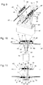
- Fig. 1 the cable drum 2 is shown in the first end position of the cable winch arrangement 1, in which the cable 30 is unwound from the cable drum 2, apart from a remaining length which is wound on the cable drum 2.
- Fig. 2 the second end position is shown, in which the rope 30 is maximally wound on the rope drum 2.
- the rope run-off point 6 is stationary, ie immobile, with respect to the support structure 20. This ensures that the cable 30 can run through the cable passage 21 regardless of the length of the section of the cable 30 wound on the cable drum 2.
- the spindle 16 in particular a section of the spindle 16 having the external thread, is in the second end position, cf. Fig. 2 , extends into the cavity 5 of the cable drum 2 over at least 70% of the longitudinal extent of the spindle 16, in particular the longitudinal extent of the external thread of the spindle 16.
- a second embodiment of a cable winch arrangement 1 according to the invention is shown.
- the structure of the cable drum 2, the drum drive 9 and the support structure 20 corresponds to that of the first exemplary embodiment, so that the explanations for the second exemplary embodiment mainly refer to the differences from the first exemplary embodiment. Apart from the differences listed below, the explanations for the first embodiment also apply to the second embodiment.
- the external thread of the spindle 16 has a pitch that is smaller than the rope diameter of the rope 30. Accordingly, the pitch of the external thread of the spindle 16 is smaller than the pitch of the spiral groove 10 of the drum jacket 4 of the rope drum 2.
- the spindle drive 14 has a transmission gear 18 .
- the transmission gear 18 transmits the rotary movement of the cable drum 2 to the spindle nut 17 of the spindle drive 14 which engages in the spindle 16.
- the transmission gear 18 is configured such that a displacement dimension of the spindle nut 17 on the spindle 16, when the cable drum 2 is rotated by one revolution, corresponds to the pitch of the groove 10 of the cable drum 2 or the cable diameter of the cable 30.
- the transmission gear 18 is attached to the bearing frame 8 in a rotationally fixed manner and transmits the twisting movement of the cable drum 2 to the spindle nut 17, with the corresponding transmission ratio of the rotational speed.
- a third exemplary embodiment of a cable winch arrangement 1 according to the invention is shown.
- the construction of the cable drum 2, the drum drive 9 and the support structure 20 corresponds to that of the first exemplary embodiment, so that the explanations for the third exemplary embodiment mainly refer to the differences from the first exemplary embodiment. Apart from the differences listed below, the explanations for the first embodiment also apply to the third embodiment.
- the external thread of the spindle 16 has a smaller pitch than the cable diameter of the rope 30. Accordingly, the pitch of the external thread of the spindle 16 is also smaller than the pitch of the spiral groove 10 of the drum shell 4 the cable drum 2.
- the pitch of the external thread of the spindle 16 corresponds at least to the rope diameter of the rope 30 and / or at least the pitch of the spiral groove 10.
- the spindle drive 14 has a spindle drive 19 for rotating the spindle 16 about the spindle axis 15 relative to the support structure 20.
- the spindle nut 17 is fastened to the bearing frame 8 in a rotationally fixed manner.
- a rotation of the spindle 16 by means of the spindle drive 19 causes the cable drum 2 to move relative to the support structure 20.
- the spindle drive 19 is controlled by means of control electronics (not shown in more detail) in such a way that the cable run-off point 6 of the cable 30, at which the cable 30 tangentially from the cable drum 2 runs up and / or runs off, is at least essentially stationary with respect to the support structure 20.
- the spindle drive 19 is by means of the Control electronics controlled in such a way that the twisting movement of the cable drum 2 and the adjustment of the cable drum 2 by means of the drum drive 9 about the drum axis 3 in a direction parallel to the drum axis 3 are coordinated with one another, that is to say synchronously, the cable run-off point 6 being at least essentially stationary with respect to the support structure 20.
- the control electronics could, for example, simultaneously control the drum drive 9 and the spindle drive 19 in order to bring about a synchronous control of the cable drum 2 and the spindle 16.
- the spindle nut 17 it would be conceivable for the spindle nut 17 to be fixed in a rotationally fixed manner on the cable drum 2. Then the rotary movement of the cable drum 2 is advantageously superimposed on that of the driven spindle 16.
- the control electronics can also be used to ensure that the cable outlet point 6 is at least essentially stationary with respect to the support structure 20.
- a crane 40 designed as a portal crane for transporting containers 41 in a container terminal.
- the crane 40 is horizontally displaceable in relation to a direction orthogonal to the plane of the drawing, the crane 40 being supported on the crane rails 49 with trolleys 45 of the crane 40, cf. Fig. 7 .
- the trolleys 45 could also be in another embodiment of the crane 40 be inflated and drive directly on the ground.
- the crane 40 also has a crane girder 42 which spans the area between the crane rails 49, ie a storage area for containers 41.
- the crane girder 42 is supported on the trolleys 45 by means of uprights 46 of the crane 40.
- a trolley 43 is movably mounted on the crane girder 42, which can also be referred to as the main girder.
- the trolley 43 is supported by trolleys, not specified, on trolley rails 47 fastened on the crane girder 42.
- the crane 40 comprises a load suspension device 44 for connection to at least one container 41.
- the load suspension device 44 hangs on the trolley 43 with ropes 30 to 37 of the trolley 43 and can be relative to the trolley 43 by lengthening or shortening the free length of the ropes 30 to 37 are moved in the vertical direction. All of this is known per se in the prior art.
- the cables 30 to 37 extending between the trolley 43 and the load-carrying device 44 together form a cable shaft, also called a cable tower.
- a cable shaft also called a cable tower.
- the trolley 43 has two cable winch arrangements 1 for winding and / or unwinding the cables 30 to 37 of the trolley 43.
- the cables 30 to 33 can be wound on a first cable drum 2 and the cables 34 to 37 on a second cable drum 2.
- the entirety of the ropes 30 to 33 could also be referred to as the first rope group and the entirety of the ropes 34 to 37 as the second rope group.
- the respective winch assembly 1 comprises a drum axis 3 rotatable mounted cable drum 2 for winding and unwinding the respective cable group, the cable winch arrangement 1 being analogous to the first exemplary embodiment according to FIG 1 and 2 , is trained. That is, the cable winch arrangement 1 has a spindle drive 14 for displacing the cable drum 2 relative to the support structure 20 of the trolley 43.
- the spindle drive 14 comprises a spindle 16 extending along a spindle axis 15 and a spindle nut 14 which engages in the spindle 16.
- the spindle drive 14 connects the support structure 20 to the cable drum 2.
- the spindle axis 15 is, as only in FIG Fig.
- the spindle 16 is - analogous to that in 1, 2 illustrated embodiment - fixed against rotation on the support structure 20.
- the pitch of the external thread of the spindle 16 corresponds to the pitch of the spiral grooves 10 to 13, the latter in Fig. 14 are drawn for one of the cable drums 2.
- the spindle drive 14 enables the cable drum 2 to be adjusted relative to the support structure 20 of the trolley 43.
- the bearing frame 8 of the cable winch arrangement 1 is supported by support rollers 22 on the support structure 20 of the trolley 43. Otherwise, with regard to the design of the cable winch arrangement 1, reference is made to the explanations given in FIGS 1, 2 illustrated first embodiment.
- the drum jacket 4 of the respective cable drum 2 has four cable groove sections, each with a groove 10, 11, 12 and 13 spaced apart from one another in a direction parallel to the drum axis 3, cf. Fig. 14 in which the grooves 10-13 for one of the cable drums 2 are shown. That is, the ropes 30 to 33 or 34 to 37 of a respective rope group run, with respect to the longitudinal extent of the respective rope drum 2, at a distance from one another from the rope drum 2 or onto the rope drum 2.
- the trolley 43 has rope pulleys 48 for deflecting a respective rope 30 to 37.
- the rope pulleys 48 have a circumferential rope groove in which the respective rope 30 to 37 is guided.
- the rope pulleys 48 have the purpose of the respective rope 30 to 37 at an anchoring point of a respective rope 30 to 37 on the To deflect the load handler 44.
- the illustrated first exemplary embodiment of the cable winch arrangement 1 provides that a respective cable run-off point of the respective cable 30 to 37 wound on the cable drum 2, on which the respective cable 30 to 37 runs tangentially from the cable drum 2 and / or runs with respect to the support structure 20 is at least essentially stationary. That is, a rotation of the cable drum 2 leads to a corresponding displacement of the cable drum 2 relative to the support structure 20, the respective cable run-off point being essentially stationary with respect to the support structure 20.
- the respective rope drain point was in the Figures 7 to 14 not shown for reasons of clarity.
- the respective rope 30 to 37 advantageously runs in the tangential direction with respect to the drum axis 3. Since the rope drain points are immovable, the number of rope pulleys 48 of the trolley 43 can be minimized, since the run-up angle of the respective rope 30 to 37 from the rope drum 2 to the respective rope pulley 48 remains constant. Conveniently, the respective rope pulleys 48 are aligned and positioned such that the respective rope 30 to 37 to be deflected is straight, i.e. without deviation from a rope groove level of the respective rope pulley 48, runs into the rope groove of the respective rope pulley 48 from the respective rope drain point.
- the 16 and 18 are identical and show that the section of the respective cable 30 to 33 running from the cable drum 2 is tangential with respect to the drum axis 3.
- 1 Winch arrangement 34 rope 2nd Rope drum 35 rope 3rd Drum axis 36 rope 4th Drum jacket 37 rope 5 cavity 6 Rope drain point 40 crane 7 Drum flange 41 Container 8th Storage rack 42 Crane girder 9 Drum drive 43 Trolley 10th groove 44 Load suspension device 11 groove 45 Crane undercarriage 12th groove 46 Stand 13 groove 47 Trolley track 14 Spindle drive 48 Rope pulley 15 Spindle axis 49 Crane rail 16 spindle 17th Spindle nut 18th Transmission gear 19th Spindle drive 20th Support structure 21 Rope passage 22 Support roller 23 distance 30th rope 31 rope 32 rope 33 rope
Landscapes
- Engineering & Computer Science (AREA)
- Mechanical Engineering (AREA)
- General Engineering & Computer Science (AREA)
- Civil Engineering (AREA)
- Structural Engineering (AREA)
- Storing, Repeated Paying-Out, And Re-Storing Of Elongated Articles (AREA)
- Unwinding Of Filamentary Materials (AREA)
- Carriers, Traveling Bodies, And Overhead Traveling Cranes (AREA)
- Ropes Or Cables (AREA)
- Storage Of Web-Like Or Filamentary Materials (AREA)
Applications Claiming Priority (2)
| Application Number | Priority Date | Filing Date | Title |
|---|---|---|---|
| ATGM154/2017U AT15602U3 (de) | 2017-07-05 | 2017-07-05 | Seilwindenanordnung |
| EP18177585.9A EP3424871B1 (fr) | 2017-07-05 | 2018-06-13 | Dispositif de treuil à câble |
Related Parent Applications (2)
| Application Number | Title | Priority Date | Filing Date |
|---|---|---|---|
| EP18177585.9A Division EP3424871B1 (fr) | 2017-07-05 | 2018-06-13 | Dispositif de treuil à câble |
| EP18177585.9A Division-Into EP3424871B1 (fr) | 2017-07-05 | 2018-06-13 | Dispositif de treuil à câble |
Publications (1)
| Publication Number | Publication Date |
|---|---|
| EP3632836A1 true EP3632836A1 (fr) | 2020-04-08 |
Family
ID=61597291
Family Applications (2)
| Application Number | Title | Priority Date | Filing Date |
|---|---|---|---|
| EP19210979.1A Withdrawn EP3632836A1 (fr) | 2017-07-05 | 2018-06-13 | Grue avec un dispositif de treuil à câble |
| EP18177585.9A Active EP3424871B1 (fr) | 2017-07-05 | 2018-06-13 | Dispositif de treuil à câble |
Family Applications After (1)
| Application Number | Title | Priority Date | Filing Date |
|---|---|---|---|
| EP18177585.9A Active EP3424871B1 (fr) | 2017-07-05 | 2018-06-13 | Dispositif de treuil à câble |
Country Status (4)
| Country | Link |
|---|---|
| US (1) | US10913640B2 (fr) |
| EP (2) | EP3632836A1 (fr) |
| AT (1) | AT15602U3 (fr) |
| CA (1) | CA3010297A1 (fr) |
Families Citing this family (15)
| Publication number | Priority date | Publication date | Assignee | Title |
|---|---|---|---|---|
| RU2740825C2 (ru) * | 2014-01-21 | 2021-01-21 | Геа Фарм Текнолоджис Канада Инк. | Приводной механизм троса |
| CN108439054A (zh) * | 2018-03-22 | 2018-08-24 | 广西和联胜电缆有限公司 | 一种电缆线自动收卷装置 |
| FR3083534A1 (fr) * | 2018-07-03 | 2020-01-10 | Psa Automobiles Sa | Dispositif motorise d’enroulement/deroulement d’un element flexible filiforme tel qu’un cable electrique |
| FR3093099B1 (fr) * | 2019-02-27 | 2021-03-12 | Manitowoc Crane Group France | Treuil à câble, notamment pour une grue |
| GB202100557D0 (en) * | 2021-01-15 | 2021-03-03 | Ocado Innovation Ltd | Winch Assembly of a Load Handling Device |
| CN113044674A (zh) * | 2021-03-17 | 2021-06-29 | 刘宁琳 | 一种电缆防堆叠压弯的卷收机构 |
| CN113202063B (zh) * | 2021-04-20 | 2024-07-30 | 陈伟 | 一种水利工程用回转式格栅除污机及其除污方法 |
| DE102022202584B3 (de) | 2022-03-16 | 2023-06-01 | Robert Bosch Gesellschaft mit beschränkter Haftung | Mehrseiliger Laststangenzug |
| CN115262498B (zh) * | 2022-08-16 | 2023-06-30 | 华南泵业有限公司 | 一种一体化泵闸专用清污装置 |
| CN115258939B (zh) * | 2022-08-30 | 2025-04-29 | 山东科技大学 | 一种电力驱动单轨吊车 |
| CN115352958A (zh) * | 2022-09-04 | 2022-11-18 | 呼图壁县万维纺织有限公司 | 一种纺织品生产加工用线束整理装置 |
| DE102023105754A1 (de) * | 2023-03-08 | 2024-09-12 | Huber Se | Rechenreinigungsvorrichtung zum Reinigen eines Rechenrosts eines Siebrechens sowie Siebrechen |
| KR102642682B1 (ko) * | 2023-11-02 | 2024-03-04 | 주식회사 에스디호이스트 | 로프 꼬임 교정용 리와인딩 장치 및 그 장치를 이용한 드럼 로프 와인딩 방법 |
| CN117550492B (zh) * | 2024-01-12 | 2024-04-05 | 河南中冶起重机集团有限公司 | 一种高稳定性的桥式起重机 |
| CN119353382A (zh) * | 2024-12-27 | 2025-01-24 | 卓轮(天津)机械有限公司 | 一种ngw无极变速器及包含其的起重机 |
Citations (7)
| Publication number | Priority date | Publication date | Assignee | Title |
|---|---|---|---|---|
| CH243432A (fr) * | 1945-01-13 | 1946-07-15 | Borgeaud Francois | Treuil transportable. |
| GB909340A (en) * | 1960-05-05 | 1962-10-31 | Atomic Energy Authority Uk | Improvements in or relating to retarding devices |
| GB2183212A (en) * | 1985-11-23 | 1987-06-03 | Handling Consultants Ltd | Apparatus for handling loads |
| DE10135034C1 (de) | 2001-07-18 | 2002-10-31 | Demag Cranes & Components Gmbh | Hubwerk mit einer Seilanordnung |
| WO2006047798A1 (fr) * | 2004-11-02 | 2006-05-11 | Franz Ehrenleitner | Dispositif de levage |
| CN102285603A (zh) * | 2011-08-15 | 2011-12-21 | 广州格睿德工程机械有限公司 | 一种驱动卷筒平移的吊杆机 |
| US20120193315A1 (en) * | 2009-08-06 | 2012-08-02 | Demag Cranes & Components Gmbh | Traveling crane having traveler and hoisting winch |
Family Cites Families (11)
| Publication number | Priority date | Publication date | Assignee | Title |
|---|---|---|---|---|
| BE569612A (fr) * | ||||
| US652893A (en) * | 1900-02-14 | 1900-07-03 | Frank E Herdman | Elevator. |
| US1221975A (en) * | 1913-04-24 | 1917-04-10 | George Cuff | Traction-engine. |
| US1866911A (en) * | 1928-04-07 | 1932-07-12 | Bernard A Schroeder | U groove traction elevator |
| US2659573A (en) * | 1951-01-26 | 1953-11-17 | Sr Joel D Smith | Safety belt cable take-up and shock absorber |
| DE1261805B (de) * | 1957-07-29 | 1968-02-22 | Passavant Werke | Rechenreiniger |
| DE8710351U1 (de) * | 1987-07-28 | 1988-01-07 | Schuster, Siegfried, 86971 Peiting | Seilwinde mit Zwangsspulung |
| DE4204153C2 (de) * | 1992-02-13 | 1994-11-24 | Licentia Gmbh | Winde |
| US5718771A (en) * | 1995-09-29 | 1998-02-17 | Brackett Green, U.S.A., Inc. | Retractable traversing trash rake and method for cleaning weedscreen |
| DE102012001592B4 (de) * | 2012-01-27 | 2019-02-28 | Liebherr-Components Biberach Gmbh | Seilwinde |
| DE102016100783A1 (de) * | 2016-01-19 | 2017-07-20 | J. Schmalz Gmbh | Winde für einen Zugstrang |
-
2017
- 2017-07-05 AT ATGM154/2017U patent/AT15602U3/de unknown
-
2018
- 2018-06-13 EP EP19210979.1A patent/EP3632836A1/fr not_active Withdrawn
- 2018-06-13 EP EP18177585.9A patent/EP3424871B1/fr active Active
- 2018-06-29 CA CA3010297A patent/CA3010297A1/fr active Pending
- 2018-07-03 US US16/026,470 patent/US10913640B2/en active Active
Patent Citations (7)
| Publication number | Priority date | Publication date | Assignee | Title |
|---|---|---|---|---|
| CH243432A (fr) * | 1945-01-13 | 1946-07-15 | Borgeaud Francois | Treuil transportable. |
| GB909340A (en) * | 1960-05-05 | 1962-10-31 | Atomic Energy Authority Uk | Improvements in or relating to retarding devices |
| GB2183212A (en) * | 1985-11-23 | 1987-06-03 | Handling Consultants Ltd | Apparatus for handling loads |
| DE10135034C1 (de) | 2001-07-18 | 2002-10-31 | Demag Cranes & Components Gmbh | Hubwerk mit einer Seilanordnung |
| WO2006047798A1 (fr) * | 2004-11-02 | 2006-05-11 | Franz Ehrenleitner | Dispositif de levage |
| US20120193315A1 (en) * | 2009-08-06 | 2012-08-02 | Demag Cranes & Components Gmbh | Traveling crane having traveler and hoisting winch |
| CN102285603A (zh) * | 2011-08-15 | 2011-12-21 | 广州格睿德工程机械有限公司 | 一种驱动卷筒平移的吊杆机 |
Also Published As
| Publication number | Publication date |
|---|---|
| AT15602U2 (de) | 2018-03-15 |
| EP3424871A2 (fr) | 2019-01-09 |
| US20190010030A1 (en) | 2019-01-10 |
| US10913640B2 (en) | 2021-02-09 |
| EP3424871C0 (fr) | 2025-08-27 |
| EP3424871A3 (fr) | 2019-05-01 |
| CA3010297A1 (fr) | 2019-01-05 |
| AT15602U3 (de) | 2018-05-15 |
| EP3424871B1 (fr) | 2025-08-27 |
Similar Documents
| Publication | Publication Date | Title |
|---|---|---|
| EP3632836A1 (fr) | Grue avec un dispositif de treuil à câble | |
| EP3280674B1 (fr) | Dispositif de transport | |
| EP1509708A1 (fr) | Dispositif d'engrenage dote d'un arbre de transmission monte excentrique sur l'axe de palier du pignon satellite | |
| DE29919877U1 (de) | Elektromotorische Verstelleinrichtung | |
| DE3209164A1 (de) | Drahtsaege | |
| DE2457864C2 (de) | Laufkatzenkran | |
| EP3620425A1 (fr) | Ascenseur déplaçable pour personnes | |
| DE69324124T2 (de) | Regalbedienungsgerät | |
| EP3009538B1 (fr) | Ouvreuse de balles | |
| DE69900555T2 (de) | Verfahren und vorrichtung zur übertragung von druck und/oder zugkraft | |
| DE1987883U (de) | Haenge - materialhandhabungsvorrichtung. | |
| DE2904110A1 (de) | Hebe- und verschiebevorrichtung fuer lasten verschiedenster art | |
| EP0080744B1 (fr) | Commande à vis pour coin | |
| AT17144U1 (de) | Energiezuführsystem | |
| DE19525921C1 (de) | Verfahren zum Aufwickeln mehrerer Halteseile und Hubwerk | |
| EP1309511B1 (fr) | Systeme de traction par enroulement | |
| WO2019002481A1 (fr) | Système muni de deux chaînes porte-câbles et d'un point de fixation déplaçable | |
| DE9110687U1 (de) | Linearantrieb | |
| DE19817933A1 (de) | Seilführung | |
| EP1116687B1 (fr) | Dispositif de levage de décors | |
| DE10135034C1 (de) | Hubwerk mit einer Seilanordnung | |
| EP4091970B1 (fr) | Dispositif de levage de charges | |
| EP2715187A1 (fr) | Concept pour un écrou de vis d'entraînement à roulements | |
| DE10012655C1 (de) | Werkzeugmaschine, insbesondere Langbett-Werkzeugmaschine | |
| EP3581817B1 (fr) | Dispositif de levage télescopique |
Legal Events
| Date | Code | Title | Description |
|---|---|---|---|
| PUAI | Public reference made under article 153(3) epc to a published international application that has entered the european phase |
Free format text: ORIGINAL CODE: 0009012 |
|
| STAA | Information on the status of an ep patent application or granted ep patent |
Free format text: STATUS: THE APPLICATION HAS BEEN PUBLISHED |
|
| AC | Divisional application: reference to earlier application |
Ref document number: 3424871 Country of ref document: EP Kind code of ref document: P |
|
| AK | Designated contracting states |
Kind code of ref document: A1 Designated state(s): AL AT BE BG CH CY CZ DE DK EE ES FI FR GB GR HR HU IE IS IT LI LT LU LV MC MK MT NL NO PL PT RO RS SE SI SK SM TR |
|
| AX | Request for extension of the european patent |
Extension state: BA ME |
|
| STAA | Information on the status of an ep patent application or granted ep patent |
Free format text: STATUS: THE APPLICATION IS DEEMED TO BE WITHDRAWN |
|
| 18D | Application deemed to be withdrawn |
Effective date: 20201009 |