EP3634177B1 - Gelenksitzvorrichtung - Google Patents
Gelenksitzvorrichtung Download PDFInfo
- Publication number
- EP3634177B1 EP3634177B1 EP18730029.8A EP18730029A EP3634177B1 EP 3634177 B1 EP3634177 B1 EP 3634177B1 EP 18730029 A EP18730029 A EP 18730029A EP 3634177 B1 EP3634177 B1 EP 3634177B1
- Authority
- EP
- European Patent Office
- Prior art keywords
- backrest
- roller
- cam
- cam track
- seat
- Prior art date
- Legal status (The legal status is an assumption and is not a legal conclusion. Google has not performed a legal analysis and makes no representation as to the accuracy of the status listed.)
- Active
Links
Images


Classifications
-
- A—HUMAN NECESSITIES
- A47—FURNITURE; DOMESTIC ARTICLES OR APPLIANCES; COFFEE MILLS; SPICE MILLS; SUCTION CLEANERS IN GENERAL
- A47C—CHAIRS; SOFAS; BEDS
- A47C1/00—Chairs adapted for special purposes
- A47C1/02—Reclining or easy chairs
- A47C1/031—Reclining or easy chairs having coupled concurrently adjustable supporting parts
- A47C1/032—Reclining or easy chairs having coupled concurrently adjustable supporting parts the parts being movably-coupled seat and back-rest
- A47C1/03205—Reclining or easy chairs having coupled concurrently adjustable supporting parts the parts being movably-coupled seat and back-rest having adjustable and lockable inclination
- A47C1/03211—Reclining or easy chairs having coupled concurrently adjustable supporting parts the parts being movably-coupled seat and back-rest having adjustable and lockable inclination by electric motors
-
- A—HUMAN NECESSITIES
- A47—FURNITURE; DOMESTIC ARTICLES OR APPLIANCES; COFFEE MILLS; SPICE MILLS; SUCTION CLEANERS IN GENERAL
- A47C—CHAIRS; SOFAS; BEDS
- A47C1/00—Chairs adapted for special purposes
- A47C1/02—Reclining or easy chairs
- A47C1/031—Reclining or easy chairs having coupled concurrently adjustable supporting parts
- A47C1/032—Reclining or easy chairs having coupled concurrently adjustable supporting parts the parts being movably-coupled seat and back-rest
- A47C1/03294—Reclining or easy chairs having coupled concurrently adjustable supporting parts the parts being movably-coupled seat and back-rest slidingly movable in the base frame, e.g. by rollers
-
- A—HUMAN NECESSITIES
- A47—FURNITURE; DOMESTIC ARTICLES OR APPLIANCES; COFFEE MILLS; SPICE MILLS; SUCTION CLEANERS IN GENERAL
- A47C—CHAIRS; SOFAS; BEDS
- A47C1/00—Chairs adapted for special purposes
- A47C1/02—Reclining or easy chairs
- A47C1/031—Reclining or easy chairs having coupled concurrently adjustable supporting parts
- A47C1/034—Reclining or easy chairs having coupled concurrently adjustable supporting parts the parts including a leg-rest or foot-rest
- A47C1/035—Reclining or easy chairs having coupled concurrently adjustable supporting parts the parts including a leg-rest or foot-rest in combination with movably coupled seat and back-rest, i.e. the seat and back-rest being movably coupled in such a way that the extension mechanism of the foot-rest is actuated at least by the relative movements of seat and backrest
- A47C1/0352—Reclining or easy chairs having coupled concurrently adjustable supporting parts the parts including a leg-rest or foot-rest in combination with movably coupled seat and back-rest, i.e. the seat and back-rest being movably coupled in such a way that the extension mechanism of the foot-rest is actuated at least by the relative movements of seat and backrest characterised by coupled seat and back-rest slidingly movable in the base frame, e.g. by rollers
-
- A—HUMAN NECESSITIES
- A47—FURNITURE; DOMESTIC ARTICLES OR APPLIANCES; COFFEE MILLS; SPICE MILLS; SUCTION CLEANERS IN GENERAL
- A47C—CHAIRS; SOFAS; BEDS
- A47C1/00—Chairs adapted for special purposes
- A47C1/02—Reclining or easy chairs
- A47C1/031—Reclining or easy chairs having coupled concurrently adjustable supporting parts
- A47C1/034—Reclining or easy chairs having coupled concurrently adjustable supporting parts the parts including a leg-rest or foot-rest
- A47C1/035—Reclining or easy chairs having coupled concurrently adjustable supporting parts the parts including a leg-rest or foot-rest in combination with movably coupled seat and back-rest, i.e. the seat and back-rest being movably coupled in such a way that the extension mechanism of the foot-rest is actuated at least by the relative movements of seat and backrest
- A47C1/0355—Reclining or easy chairs having coupled concurrently adjustable supporting parts the parts including a leg-rest or foot-rest in combination with movably coupled seat and back-rest, i.e. the seat and back-rest being movably coupled in such a way that the extension mechanism of the foot-rest is actuated at least by the relative movements of seat and backrest actuated by linkages, e.g. lazy-tongs mechanisms
-
- A—HUMAN NECESSITIES
- A61—MEDICAL OR VETERINARY SCIENCE; HYGIENE
- A61G—TRANSPORT, PERSONAL CONVEYANCES, OR ACCOMMODATION SPECIALLY ADAPTED FOR PATIENTS OR DISABLED PERSONS; OPERATING TABLES OR CHAIRS; CHAIRS FOR DENTISTRY; FUNERAL DEVICES
- A61G5/00—Chairs or personal conveyances specially adapted for patients or disabled persons, e.g. wheelchairs
- A61G5/10—Parts, details or accessories
- A61G5/1056—Arrangements for adjusting the seat
- A61G5/1067—Arrangements for adjusting the seat adjusting the backrest relative to the seat portion
-
- A—HUMAN NECESSITIES
- A61—MEDICAL OR VETERINARY SCIENCE; HYGIENE
- A61G—TRANSPORT, PERSONAL CONVEYANCES, OR ACCOMMODATION SPECIALLY ADAPTED FOR PATIENTS OR DISABLED PERSONS; OPERATING TABLES OR CHAIRS; CHAIRS FOR DENTISTRY; FUNERAL DEVICES
- A61G5/00—Chairs or personal conveyances specially adapted for patients or disabled persons, e.g. wheelchairs
- A61G5/10—Parts, details or accessories
- A61G5/1056—Arrangements for adjusting the seat
- A61G5/1075—Arrangements for adjusting the seat tilting the whole seat backwards
Definitions
- the invention relates to the field of articulated seats with a view to modifying the seat in an ergonomic sense.
- the invention relates in particular to applications as varied as domestic seats, office seats, automobile, train or airplane seats, relaxation seats, or seats or armchairs for sick or disabled people.
- the articulation mechanisms allowing the movements of such seats are covered by the invention.
- the seats and articulated mechanisms according to the invention allow so-called conventional postures but also so-called relaxation postures. To do this, the mechanisms allowing the relative movements, in particular of the seat and the backrest, are assisted and motorized.
- an articulated seat comprising a base which supports, through an articulated connection, a seat, a backrest and a support element for the legs.
- An articulation with connecting rods and jack allows easy passage between several positions, in particular between a seated position to a position in inclined elevation. This mechanism is relatively complex to implement, by the number of parts involved as well as by the associated connections.
- the invention aims to remedy the drawbacks of the state of the art and in particular to provide an articulated seat device of simple design but allowing relative movements of the seat and of the backrest of great amplitude which induces good reliability.
- the invention therefore relates to an articulated seat device comprising a fixed base on which rests a movable assembly comprising a seat and a movable backrest relative to the base by virtue of an articulation mechanism cooperating with a motorized means.
- the articulation mechanism comprises at least one multilinear path cam fixed on the base and in which slides a roller cooperating with said motorized means which ensures its displacement in both directions of the multilinear path.
- said cam being flat and oriented in a longitudinal plane of the seat.
- longitudinal plane of the seat is meant a plane which contains a longitudinal axis of the seat, that is to say an axis which extends along the length or greatest dimension of the seat.
- said motorized means comprises a single actuator controlled by a motor, to which said roller is connected.
- said motorized means comprises a motorized roller cooperating with a cam provided with teeth provided on said cam track.
- the teeth are erected towards the inside of the path of cam, in the main plane of the cam and they cooperate with those of the pinion; here we have a pinion-rack gear type connection.
- said cam track comprises a first, second and third substantially linear portions, and juxtaposed. It is therefore a unique and relatively easy to manufacture part which is chosen here to define the movements of this articulated seat. The movements induced by such a cam profile are adapted to the desired synchronizations and allow interesting amplitudes.
- the first portion of said cam track is substantially vertical and allows, when the roller traverses it, the simultaneous rotation of the seat and of the backrest around a first axis of rotation O perpendicular to the longitudinal axis L of the device and located substantially in the middle of the seat.
- the second portion of said cam track forms an angle of approximately 120 ° with the first portion of said path, the respective curvatures of the first and second portions forming a concavity, and in that the second portion of the cam track cam allows, when the roller traverses it, the rotation of the backrest relative to the seat around a second axis of rotation O1 constituting the common pivot edge between the backrest and the seat, said second axis of rotation being perpendicular to the longitudinal axis L.
- the third portion of the cam track is substantially parallel to the first portion of the cam track so as to form an inflection point with the second portion, said third portion allowing, when the roller traverses it, the rotation of the backrest and seat around the first axis of rotation O.
- the articulated seat may further comprise means capable of allowing the support of the lower limbs, and means for controlling their movement which cooperate with the motorized means and the cam.
- the means for controlling the movement of the supports of the lower limbs are functionally linked to the roller, preferably in the third portion of said cam track.
- the means for controlling the movement of the supports comprise a first connecting rod having a first end capable of sliding in a part of the cam track and a second end cooperating with a first end of a second connecting rod. , said second link cooperating at its second end with a first end of a third link, the second end of which constitutes a pivot connection with the support for the lower limbs.
- said actuator can be fixed on the base at the level of the bottom of the backrest. Without departing from the scope of the invention, said actuator can be fixed to the backrest, in its uppermost part.
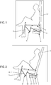
- the figures 1 to 5 show both the positions of the articulated seat according to the invention and the particular mechanical connections making it possible to obtain these different positions.
- the fixed base (except the cam) is not illustrated in these figures for reasons of clarity of description; only the mobile assembly is therefore represented.
- This movable assembly comprises in particular a seat 1 and a backrest 2 movable relative to each other and relative to the fixed base.
- the articulation mechanism is shown diagrammatically and comprises a cam 4 with a non-linear path which cooperates with a motorized means such as a jack (not shown in the figures 1 to 5 ) and a roller 5 fixed to the cylinder.
- the roller 5 is shown schematically by a point, here placed at the bottom of the backrest 2.
- the mechanism may additionally comprise means 3 capable of allowing the support of the lower limbs such as the legs or the feet.
- a connecting rod mechanism 6 is provided, operatively connected both with the lower surface of the legrest 3 and with the cam track.
- the articulated seat device is in the so-called starting position where the seat 1 is horizontal and where the backrest 2 makes an angle of approximately 95 ° with the seat 1.
- the roller 5 is placed at one end of the cam track .
- the figure 2 illustrates a so-called security position; a rotation around a first axis O of the whole of the seat device is effected between the starting position of the figure 1 and that of the figure 2 .
- the roller 5 has moved in the cam track, on a first portion 41. This position, with a slight inclination of the seat towards the rear of the seat, prevents the seated person from sliding forward. ; in other words, she holds him in the sitting position.
- the figure 3 differs from figure 2 by the position of the backrest 2 which has rotated around a second axis O1 vis-à-vis the seat 1. This is the only movement observed in this phase. Between the position of the figure 2 and the one at the figure 3 , the roller 5 has traveled a second portion 42 of the cam track. The user is thus in a semi-relaxed position. Note that during all these phases, the leg support remained motionless.
- the figure 4 shows a so-called comfort position in which the user is almost lying down.
- the seat 1 and the backrest 2 have made a simultaneous rotation of approximately 35 °.
- the roller 5 has started its course in the third portion 43 of the cam track. At the same time, the roller 5 has come into contact with the end of the connecting rod system so that the leg support 3 has started to move.
- the figure 5 illustrates a position of total relaxation in which the legrests are fully extended and have an almost horizontal position. Between the positions of the figure 4 and some figure 5 , the roller has traveled the entire third portion 43 of the cam track. It comes to a stop at the end of the cam track.
- the figure 6 is a diagram showing the different positions of the articulated seat, from the seated position (1) to the fully relaxed position (4).
- the first axis O is fixed relative to the fixed base (not shown) and, consequently, the cam 4.
- the seat 1 is thus mounted so as to be able to rotate about the first axis 0 relative to the fixed base and the backrest 2 is mounted so as to be able to rotate around the second axis O1 on the seat.
- the roller 5 traversing the cam 4 is located at the bottom of the backrest 2.
- the means of motorization of the device comprises, according to a preferred embodiment of the invention, a single cylinder which, depending on the direction required for the movement, exerts a thrust or else a traction on the roller which itself causes successively rotations around the first axis O (simultaneous rotation of the seat and the backrest) and around the second axis O1 (rotation of the backrest with respect to the seat).
- a fluid movement is obtained, in one direction as in the other direction of movement.
- the angle points of the cam track in no way disturb the operation of the seat according to the invention; on the contrary, they make it possible to achieve a damping of the speed of the movement at each change of trajectory in the cam path. Smooth movement of the seat and backrest results.
- This is due to the diameter of the roller which induces a rotation of this one around its instantaneous axis of rotation (point of contact between the roller and the cam track) at the level of the trajectory changes, which prevents a sharp angle trajectory. of the roller and creates a damping of the speed of the movement.
- the diameter of the roller implies fluid sequences of movements; the larger the diameter of the roller, the lower the acceleration / deceleration stops and starts.
- the figure 7 shows the cam 4 which is a flat part of a certain thickness, for example 12 mm, made of steel by a laser cutting machine or by a sheet metal punching machine or else by machining, by molding.
- the cam 4 is placed in a longitudinal plane of the seat. According to the mechanical stresses undergone by the roller and linked in particular to the maximum weight of the person supported by the seat, the dimensioning of the roller is carried out by those skilled in the art according to the rules of the art.
- the positions of the rotation axes O1, 02, of the jack represent parameters taken into account.
- the figure 7 illustrates the cam track defined according to the illustrated embodiment, and which makes it possible to induce the relative and absolute movements of the seat 1 and of the backrest 2, or even of the legrest 3.
- a first portion 41 substantially straight but which has a slight curvature, the general orientation of which is close to the vertical.
- the second portion 42 of the cam track is substantially straight but slightly curved; it forms an angle of approximately 120 ° with the first portion 41 and these two portions together form a concavity.
- the third portion 43 which connects with the second portion at an inflection point.
- the third portion 43 is substantially parallel to the first portion 41.
- the number and geometry of the constituent portions of the cam track depend on the desired movement sequences of the seat 1 and of the back 2.
- the width of the cam track is calculated and the dimensions of the roller which travels therein are chosen accordingly.
- the dimensions of the running roller are as follows: thickness of 11mm; 19mm diameter, for a cam having a thickness of 12mm.
- an assembly consisting of a rotary motor, a pinion can form a motorized roller; teeth are then provided on the cam track, which cooperates with the motorized roller.
- This assembly replaces the cylinder, roller and smooth cam assembly described above.
- a first connecting rod 61 has a first end capable of sliding in a part of the cam track and a second end cooperates with a first end of a second connecting rod; said second connecting rod 62 cooperates via its second end with a first end of a third connecting rod 63, of which the second end constitutes a pivot connection with the leg or footrest support 3.
- the roller 5 exerts a thrust force, in the third portion 43 of the cam track, which makes it possible to move the leg support 3 from an almost vertical position to a horizontal position.
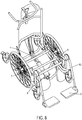
- the figure 8 illustrates by a schematic perspective view a wheelchair according to the invention.
- a support 3 which is here a support for the feet; the control means of the support 3, namely the connecting rods are also shown, in particular the third connecting rod 63.
- the joint according to a preferred embodiment of the invention is shown on figure 9 where we see in particular the cam 4 comprising three portions 41, 42, 43 of the cam track.
- the roller 5 is here placed at the end of the cam track and it can be seen that the arm of the jack 7 is then extended.
- a motor 8 makes it possible to actuate the jack 7.
- a control unit (not shown) makes it possible to control not only this motorization but also any other technically equivalent means and any additional means useful for the proper functioning of the invention.
Landscapes
- Health & Medical Sciences (AREA)
- General Health & Medical Sciences (AREA)
- Dentistry (AREA)
- Life Sciences & Earth Sciences (AREA)
- Animal Behavior & Ethology (AREA)
- Public Health (AREA)
- Veterinary Medicine (AREA)
- Chairs For Special Purposes, Such As Reclining Chairs (AREA)
- Seats For Vehicles (AREA)
Claims (11)
- Gelenksitzvorrichtung, umfassend einen feststehenden Sockel, auf dem eine bewegliche Einheit aufliegt, die eine in Bezug auf den Sockel dank eines Gelenkmechanismus, der mit einem motorisierten Mittel (7, 8) zusammenwirkt, bewegliche Sitzfläche (1) und Rückenlehne (2) umfasst, dadurch gekennzeichnet, dass die Sitzfläche (1) entlang einer ersten feststehenden Drehachse (O) drehbeweglich auf dem Sockel montiert ist, dadurch, dass die Rückenlehne entlang einer zweiten Drehachse (O1) drehbeweglich an der Sitzfläche montiert ist, und dadurch, dass der Gelenkmechanismus mindestens eine Kurvenscheibe (4) mit mehrliniger Bahn umfasst, die an dem Sockel befestigt ist, und in der eine Laufrolle (5) gleitet, die mit dem motorisierten Mittel (7, 8) zusammenwirkt, das für deren Fortbewegung in die beiden Richtungen der mehrlinigen Bahn sorgt, wobei die Kurvenscheibe flach, und in einer Längsebene des Sitzes ausgerichtet ist, wobei die (5) am unteren Teil der Rückenlehne (2) montiert ist.
- Vorrichtung nach Anspruch 1, dadurch gekennzeichnet, dass das motorisierte Mittel einen einzigen Zylinder (7) umfasst, der durch einen Motor (8) gesteuert wird, mit dem die Laufrolle (5) verbunden ist.
- Vorrichtung nach Anspruch 1, dadurch gekennzeichnet, dass die Laufrolle (5) motorisiert ist, und mit einer Kurvenscheibe (4) zusammenwirkt, die mit Zähnen versehen ist, die an der Kurvenscheibenbahn vorgesehen sind.
- Gelenksitzvorrichtung nach einem der vorstehenden Ansprüche, dadurch gekennzeichnet, dass die Kurvenscheibenbahn einen ersten (41), einen zweiten (42) und einen dritten (43) im Wesentlichen linearen und nebeneinandergestellten Abschnitt beinhaltet.
- Sitzvorrichtung nach Anspruch 4, dadurch gekennzeichnet, dass der erste Abschnitt (41) der Kurvenscheibenbahn im Wesentlichen vertikal ist und, wenn die Laufrolle durch sie hindurchläuft, die gleichzeitige Drehung der Sitzfläche und der Rückenlehne um die erste Drehachse (O) herum, senkrecht zur Längsachse (L) der Vorrichtung ermöglicht, und im Wesentlichen in der Mitte der Sitzfläche gelegen ist.
- Sitzvorrichtung nach Anspruch 4 oder Anspruch 5, dadurch gekennzeichnet, dass der zweite Abschnitt (42) der Kurvenscheibenbahn einen Winkel von etwa 120° mit dem ersten Abschnitt (41) der Bahn bildet, wobei die jeweiligen Krümmungen des ersten und des zweiten Abschnitts eine Konkavität bilden, und dadurch, dass der zweite Abschnitt der Kurvenscheibenbahn, wenn die Laufrolle durch sie hindurchläuft, die Drehung der Rückenlehne in Bezug auf die Sitzfläche um die zweite Drehachse (O1) herum, die die gemeinsame Kippkante zwischen der Rückenlehne und der Sitzfläche darstellt, ermöglicht, wobei die zweite Drehachse senkrecht zur Längsachse (L) ist.
- Sitzvorrichtung nach einem der Ansprüche 4 bis 6, dadurch gekennzeichnet, dass der dritte Abschnitt (43) der Kurvenscheibenbahn im Wesentlichen parallel zum ersten Abschnitt der Kurvenscheibenbahn ist, um einen Flexionspunkt mit dem zweiten Abschnitt zu bilden, wobei der dritte Abschnitt, wenn die Laufrolle durch ihn hindurchläuft, die Drehung der Rückenlehne und der Sitzfläche um die erste Drehachse (O) herum ermöglicht.
- Sitzvorrichtung nach einem der vorstehenden Ansprüche, dadurch gekennzeichnet, dass sie weiter Mittel (3) umfasst, die imstande sind, das Abstützen der unteren Gliedmaßen zu ermöglichen, und Mittel (6) zum Steuern von deren Bewegung, die mit dem motorisierten Mittel und der Kurvenscheibe zusammenwirken.
- Vorrichtung nach Anspruch 8, dadurch gekennzeichnet, dass die Mittel (6) zum Steuern der Bewegung der Abstützungen (3) betrieblich mit der Laufrolle (5), vorzugsweise im dritten Abschnitt (43) der Kurvenscheibenbahn verbunden sind.
- Vorrichtung nach Anspruch 8 oder Anspruch 9, dadurch gekennzeichnet, dass die Mittel (6) zum Steuern der Bewegung der Abstützungen (3) eine erste Triebstange (61) umfassen, das ein erstes Ende aufweist, das imstande ist, in einem Teil der Kurvenscheibenbahn zu gleiten, und ein zweites Ende, das mit dem ersten Ende einer zweiten Triebstange (62) zusammenwirkt, wobei die zweite Triebstange durch ihr zweites Ende mit einem ersten Ende einer dritten Triebstange (63) zusammenwirkt, deren zweites Ende eine Kippverbindung mit der Beinabstützung (3) darstellt.
- Vorrichtung nach einem der Ansprüche 2 bis 10, dadurch gekennzeichnet, dass der Zylinder an dem Sockel im Bereich des unteren Teils der Rückenlehne befestigt ist.
Applications Claiming Priority (2)
| Application Number | Priority Date | Filing Date | Title |
|---|---|---|---|
| FR1754962A FR3066896B1 (fr) | 2017-06-05 | 2017-06-05 | Dispositif de siege articule. |
| PCT/FR2018/051251 WO2018224751A1 (fr) | 2017-06-05 | 2018-05-31 | Dispositif de siège articulé |
Publications (2)
| Publication Number | Publication Date |
|---|---|
| EP3634177A1 EP3634177A1 (de) | 2020-04-15 |
| EP3634177B1 true EP3634177B1 (de) | 2021-07-07 |
Family
ID=59811477
Family Applications (1)
| Application Number | Title | Priority Date | Filing Date |
|---|---|---|---|
| EP18730029.8A Active EP3634177B1 (de) | 2017-06-05 | 2018-05-31 | Gelenksitzvorrichtung |
Country Status (4)
| Country | Link |
|---|---|
| EP (1) | EP3634177B1 (de) |
| ES (1) | ES2896685T3 (de) |
| FR (1) | FR3066896B1 (de) |
| WO (1) | WO2018224751A1 (de) |
Families Citing this family (2)
| Publication number | Priority date | Publication date | Assignee | Title |
|---|---|---|---|---|
| US11628103B2 (en) | 2020-04-28 | 2023-04-18 | Toyota Motor North America, Inc. | Support devices including movable leg segments and methods for operating the same |
| US11559445B2 (en) | 2020-04-28 | 2023-01-24 | Toyota Motor North America, Inc. | Support devices including movable leg segments and methods for operating the same |
Family Cites Families (8)
| Publication number | Priority date | Publication date | Assignee | Title |
|---|---|---|---|---|
| US6450578B1 (en) | 2000-08-18 | 2002-09-17 | Michael Blake Taggett | Ergonomic chair |
| DE102005016943B4 (de) * | 2005-04-12 | 2006-11-30 | Stanzwerk Wetter Sichelschmidt Gmbh & Co. Kg | Ottomane |
| DE202005014571U1 (de) | 2005-09-15 | 2005-11-17 | Kintec-Solution Gmbh | Sessel |
| DE202005017987U1 (de) | 2005-11-17 | 2006-01-12 | Kintec-Solution Gmbh | Sessel |
| GB0704546D0 (en) * | 2007-03-08 | 2007-04-18 | Contour Premium Aircraft Seati | Adjustable seat |
| FR2917679B1 (fr) * | 2007-06-22 | 2010-01-08 | Antolin Grupo Ing Sa | Siege escamotable notamment pour vehicule automobile |
| JP4435215B2 (ja) * | 2007-07-19 | 2010-03-17 | 三洋電機株式会社 | 椅子型マッサージ機 |
| FR3013953A1 (fr) | 2013-12-02 | 2015-06-05 | Innov Sa | Dispositif de siege articule |
-
2017
- 2017-06-05 FR FR1754962A patent/FR3066896B1/fr not_active Expired - Fee Related
-
2018
- 2018-05-31 EP EP18730029.8A patent/EP3634177B1/de active Active
- 2018-05-31 ES ES18730029T patent/ES2896685T3/es active Active
- 2018-05-31 WO PCT/FR2018/051251 patent/WO2018224751A1/fr not_active Ceased
Non-Patent Citations (1)
| Title |
|---|
| None * |
Also Published As
| Publication number | Publication date |
|---|---|
| FR3066896A1 (fr) | 2018-12-07 |
| ES2896685T3 (es) | 2022-02-25 |
| EP3634177A1 (de) | 2020-04-15 |
| FR3066896B1 (fr) | 2021-01-29 |
| WO2018224751A1 (fr) | 2018-12-13 |
Similar Documents
| Publication | Publication Date | Title |
|---|---|---|
| EP1345810B1 (de) | In ein bett umwandelbarer sitz, insbesondere für ein flugzeug | |
| EP1228963B1 (de) | Mehrstellungsfluggastsitz | |
| EP2878481B1 (de) | Passagiersitz mit Schalensitzstruktur und einstellbarer Position | |
| EP1352828A1 (de) | Sitz mit mechanischer Synchronisierung von Rückenlehne und Beinstütze | |
| EP0121452A1 (de) | Sitzlehnengelenk für Fahrzeuge | |
| FR3086595A1 (fr) | Siège de véhicule à mouvement pivotant vertical | |
| EP3634177B1 (de) | Gelenksitzvorrichtung | |
| WO2013167822A1 (fr) | Siege articule dote d'un mouvement synchrone ente l'assise et le dossier | |
| EP0268514B1 (de) | Vorrichtung zum Einstellen der Höhe und der Sitzfläche eines Sitzes, insbesondere eines Fahrzeugsitzes | |
| FR2599313A1 (fr) | Siecle de vehicule comportant une surface d'assise reglable en hauteur et en inclinaison. | |
| FR2498132A1 (fr) | Dispositif de reglage en hauteur d'un element, notamment d'un siege de vehicule | |
| EP1537805B1 (de) | Ruhemöbel wie ein Sofa, Sessel oder Sitz zum Gebrauch in der Nähe einer Wand. | |
| FR2905355A1 (fr) | Sous-ensemble de cabine d'aeronef et aeronef comportant un tel sous-ensemble | |
| FR3086599A1 (fr) | Systeme comprenant un siege de vehicule a dossier inclinable | |
| FR2719263A1 (fr) | Articulation de dossier pour un siège de véhicule comprenant un support d'assise et un dossier articulé à ce support. | |
| FR2789142A1 (fr) | Mecanisme de reglage, et ensemble d'assise comportant un tel mecanisme | |
| EP2581260B1 (de) | Passagiersitz für Transportschienenfahrzeug | |
| FR2487652A1 (fr) | Mecanisme d'articulation reglable, notamment pour dossier de siege | |
| FR3074109A1 (fr) | Siege de vehicule au confort ameliore | |
| EP3398808B1 (de) | Drehsitz mit hochklappbarer fussstütze, insbesondere für schienenfahrzeug | |
| EP0156814B1 (de) | Gegliederter sitz | |
| CA2441990A1 (fr) | Lit muni d'un releve-dos | |
| FR2828150A1 (fr) | Siege d'automobile comportant un dossier rabattable a largeur variable | |
| EP3808593B1 (de) | Sitz mit reversibler rückenlehne, der mit feststehenden armlehnen ausgestattet ist | |
| EP3398805B1 (de) | Gesicherte vorrichtung zum drehen eines sitzes, insbesondere für ein schienenfahrzeug |
Legal Events
| Date | Code | Title | Description |
|---|---|---|---|
| STAA | Information on the status of an ep patent application or granted ep patent |
Free format text: STATUS: UNKNOWN |
|
| STAA | Information on the status of an ep patent application or granted ep patent |
Free format text: STATUS: THE INTERNATIONAL PUBLICATION HAS BEEN MADE |
|
| PUAI | Public reference made under article 153(3) epc to a published international application that has entered the european phase |
Free format text: ORIGINAL CODE: 0009012 |
|
| STAA | Information on the status of an ep patent application or granted ep patent |
Free format text: STATUS: REQUEST FOR EXAMINATION WAS MADE |
|
| 17P | Request for examination filed |
Effective date: 20191112 |
|
| AK | Designated contracting states |
Kind code of ref document: A1 Designated state(s): AL AT BE BG CH CY CZ DE DK EE ES FI FR GB GR HR HU IE IS IT LI LT LU LV MC MK MT NL NO PL PT RO RS SE SI SK SM TR |
|
| AX | Request for extension of the european patent |
Extension state: BA ME |
|
| DAV | Request for validation of the european patent (deleted) | ||
| DAX | Request for extension of the european patent (deleted) | ||
| GRAP | Despatch of communication of intention to grant a patent |
Free format text: ORIGINAL CODE: EPIDOSNIGR1 |
|
| STAA | Information on the status of an ep patent application or granted ep patent |
Free format text: STATUS: GRANT OF PATENT IS INTENDED |
|
| INTG | Intention to grant announced |
Effective date: 20210301 |
|
| GRAS | Grant fee paid |
Free format text: ORIGINAL CODE: EPIDOSNIGR3 |
|
| GRAA | (expected) grant |
Free format text: ORIGINAL CODE: 0009210 |
|
| STAA | Information on the status of an ep patent application or granted ep patent |
Free format text: STATUS: THE PATENT HAS BEEN GRANTED |
|
| AK | Designated contracting states |
Kind code of ref document: B1 Designated state(s): AL AT BE BG CH CY CZ DE DK EE ES FI FR GB GR HR HU IE IS IT LI LT LU LV MC MK MT NL NO PL PT RO RS SE SI SK SM TR |
|
| REG | Reference to a national code |
Ref country code: GB Ref legal event code: FG4D Free format text: NOT ENGLISH |
|
| REG | Reference to a national code |
Ref country code: AT Ref legal event code: REF Ref document number: 1407710 Country of ref document: AT Kind code of ref document: T Effective date: 20210715 |
|
| REG | Reference to a national code |
Ref country code: DE Ref legal event code: R096 Ref document number: 602018019752 Country of ref document: DE |
|
| REG | Reference to a national code |
Ref country code: IE Ref legal event code: FG4D Free format text: LANGUAGE OF EP DOCUMENT: FRENCH |
|
| REG | Reference to a national code |
Ref country code: LT Ref legal event code: MG9D |
|
| REG | Reference to a national code |
Ref country code: NL Ref legal event code: MP Effective date: 20210707 |
|
| REG | Reference to a national code |
Ref country code: AT Ref legal event code: MK05 Ref document number: 1407710 Country of ref document: AT Kind code of ref document: T Effective date: 20210707 |
|
| PG25 | Lapsed in a contracting state [announced via postgrant information from national office to epo] |
Ref country code: LT Free format text: LAPSE BECAUSE OF FAILURE TO SUBMIT A TRANSLATION OF THE DESCRIPTION OR TO PAY THE FEE WITHIN THE PRESCRIBED TIME-LIMIT Effective date: 20210707 Ref country code: BG Free format text: LAPSE BECAUSE OF FAILURE TO SUBMIT A TRANSLATION OF THE DESCRIPTION OR TO PAY THE FEE WITHIN THE PRESCRIBED TIME-LIMIT Effective date: 20211007 Ref country code: AT Free format text: LAPSE BECAUSE OF FAILURE TO SUBMIT A TRANSLATION OF THE DESCRIPTION OR TO PAY THE FEE WITHIN THE PRESCRIBED TIME-LIMIT Effective date: 20210707 Ref country code: NL Free format text: LAPSE BECAUSE OF FAILURE TO SUBMIT A TRANSLATION OF THE DESCRIPTION OR TO PAY THE FEE WITHIN THE PRESCRIBED TIME-LIMIT Effective date: 20210707 Ref country code: PT Free format text: LAPSE BECAUSE OF FAILURE TO SUBMIT A TRANSLATION OF THE DESCRIPTION OR TO PAY THE FEE WITHIN THE PRESCRIBED TIME-LIMIT Effective date: 20211108 Ref country code: NO Free format text: LAPSE BECAUSE OF FAILURE TO SUBMIT A TRANSLATION OF THE DESCRIPTION OR TO PAY THE FEE WITHIN THE PRESCRIBED TIME-LIMIT Effective date: 20211007 Ref country code: FI Free format text: LAPSE BECAUSE OF FAILURE TO SUBMIT A TRANSLATION OF THE DESCRIPTION OR TO PAY THE FEE WITHIN THE PRESCRIBED TIME-LIMIT Effective date: 20210707 Ref country code: HR Free format text: LAPSE BECAUSE OF FAILURE TO SUBMIT A TRANSLATION OF THE DESCRIPTION OR TO PAY THE FEE WITHIN THE PRESCRIBED TIME-LIMIT Effective date: 20210707 Ref country code: RS Free format text: LAPSE BECAUSE OF FAILURE TO SUBMIT A TRANSLATION OF THE DESCRIPTION OR TO PAY THE FEE WITHIN THE PRESCRIBED TIME-LIMIT Effective date: 20210707 Ref country code: SE Free format text: LAPSE BECAUSE OF FAILURE TO SUBMIT A TRANSLATION OF THE DESCRIPTION OR TO PAY THE FEE WITHIN THE PRESCRIBED TIME-LIMIT Effective date: 20210707 |
|
| REG | Reference to a national code |
Ref country code: ES Ref legal event code: FG2A Ref document number: 2896685 Country of ref document: ES Kind code of ref document: T3 Effective date: 20220225 |
|
| PG25 | Lapsed in a contracting state [announced via postgrant information from national office to epo] |
Ref country code: PL Free format text: LAPSE BECAUSE OF FAILURE TO SUBMIT A TRANSLATION OF THE DESCRIPTION OR TO PAY THE FEE WITHIN THE PRESCRIBED TIME-LIMIT Effective date: 20210707 Ref country code: LV Free format text: LAPSE BECAUSE OF FAILURE TO SUBMIT A TRANSLATION OF THE DESCRIPTION OR TO PAY THE FEE WITHIN THE PRESCRIBED TIME-LIMIT Effective date: 20210707 Ref country code: GR Free format text: LAPSE BECAUSE OF FAILURE TO SUBMIT A TRANSLATION OF THE DESCRIPTION OR TO PAY THE FEE WITHIN THE PRESCRIBED TIME-LIMIT Effective date: 20211008 |
|
| REG | Reference to a national code |
Ref country code: DE Ref legal event code: R097 Ref document number: 602018019752 Country of ref document: DE |
|
| PG25 | Lapsed in a contracting state [announced via postgrant information from national office to epo] |
Ref country code: DK Free format text: LAPSE BECAUSE OF FAILURE TO SUBMIT A TRANSLATION OF THE DESCRIPTION OR TO PAY THE FEE WITHIN THE PRESCRIBED TIME-LIMIT Effective date: 20210707 |
|
| PLBE | No opposition filed within time limit |
Free format text: ORIGINAL CODE: 0009261 |
|
| STAA | Information on the status of an ep patent application or granted ep patent |
Free format text: STATUS: NO OPPOSITION FILED WITHIN TIME LIMIT |
|
| PG25 | Lapsed in a contracting state [announced via postgrant information from national office to epo] |
Ref country code: SM Free format text: LAPSE BECAUSE OF FAILURE TO SUBMIT A TRANSLATION OF THE DESCRIPTION OR TO PAY THE FEE WITHIN THE PRESCRIBED TIME-LIMIT Effective date: 20210707 Ref country code: SK Free format text: LAPSE BECAUSE OF FAILURE TO SUBMIT A TRANSLATION OF THE DESCRIPTION OR TO PAY THE FEE WITHIN THE PRESCRIBED TIME-LIMIT Effective date: 20210707 Ref country code: RO Free format text: LAPSE BECAUSE OF FAILURE TO SUBMIT A TRANSLATION OF THE DESCRIPTION OR TO PAY THE FEE WITHIN THE PRESCRIBED TIME-LIMIT Effective date: 20210707 Ref country code: EE Free format text: LAPSE BECAUSE OF FAILURE TO SUBMIT A TRANSLATION OF THE DESCRIPTION OR TO PAY THE FEE WITHIN THE PRESCRIBED TIME-LIMIT Effective date: 20210707 Ref country code: CZ Free format text: LAPSE BECAUSE OF FAILURE TO SUBMIT A TRANSLATION OF THE DESCRIPTION OR TO PAY THE FEE WITHIN THE PRESCRIBED TIME-LIMIT Effective date: 20210707 Ref country code: AL Free format text: LAPSE BECAUSE OF FAILURE TO SUBMIT A TRANSLATION OF THE DESCRIPTION OR TO PAY THE FEE WITHIN THE PRESCRIBED TIME-LIMIT Effective date: 20210707 |
|
| 26N | No opposition filed |
Effective date: 20220408 |
|
| PGFP | Annual fee paid to national office [announced via postgrant information from national office to epo] |
Ref country code: IT Payment date: 20220531 Year of fee payment: 5 Ref country code: GB Payment date: 20220531 Year of fee payment: 5 Ref country code: ES Payment date: 20220607 Year of fee payment: 5 |
|
| PGFP | Annual fee paid to national office [announced via postgrant information from national office to epo] |
Ref country code: DE Payment date: 20220629 Year of fee payment: 5 |
|
| REG | Reference to a national code |
Ref country code: CH Ref legal event code: PL |
|
| REG | Reference to a national code |
Ref country code: BE Ref legal event code: MM Effective date: 20220531 |
|
| PG25 | Lapsed in a contracting state [announced via postgrant information from national office to epo] |
Ref country code: MC Free format text: LAPSE BECAUSE OF FAILURE TO SUBMIT A TRANSLATION OF THE DESCRIPTION OR TO PAY THE FEE WITHIN THE PRESCRIBED TIME-LIMIT Effective date: 20210707 Ref country code: LU Free format text: LAPSE BECAUSE OF NON-PAYMENT OF DUE FEES Effective date: 20220531 Ref country code: LI Free format text: LAPSE BECAUSE OF NON-PAYMENT OF DUE FEES Effective date: 20220531 Ref country code: CH Free format text: LAPSE BECAUSE OF NON-PAYMENT OF DUE FEES Effective date: 20220531 |
|
| PG25 | Lapsed in a contracting state [announced via postgrant information from national office to epo] |
Ref country code: IE Free format text: LAPSE BECAUSE OF NON-PAYMENT OF DUE FEES Effective date: 20220531 |
|
| PG25 | Lapsed in a contracting state [announced via postgrant information from national office to epo] |
Ref country code: BE Free format text: LAPSE BECAUSE OF NON-PAYMENT OF DUE FEES Effective date: 20220531 |
|
| PGFP | Annual fee paid to national office [announced via postgrant information from national office to epo] |
Ref country code: FR Payment date: 20230531 Year of fee payment: 6 |
|
| REG | Reference to a national code |
Ref country code: DE Ref legal event code: R119 Ref document number: 602018019752 Country of ref document: DE |
|
| GBPC | Gb: european patent ceased through non-payment of renewal fee |
Effective date: 20230531 |
|
| PG25 | Lapsed in a contracting state [announced via postgrant information from national office to epo] |
Ref country code: MK Free format text: LAPSE BECAUSE OF FAILURE TO SUBMIT A TRANSLATION OF THE DESCRIPTION OR TO PAY THE FEE WITHIN THE PRESCRIBED TIME-LIMIT Effective date: 20210707 Ref country code: IT Free format text: LAPSE BECAUSE OF NON-PAYMENT OF DUE FEES Effective date: 20230531 Ref country code: DE Free format text: LAPSE BECAUSE OF NON-PAYMENT OF DUE FEES Effective date: 20231201 Ref country code: CY Free format text: LAPSE BECAUSE OF FAILURE TO SUBMIT A TRANSLATION OF THE DESCRIPTION OR TO PAY THE FEE WITHIN THE PRESCRIBED TIME-LIMIT Effective date: 20210707 Ref country code: GB Free format text: LAPSE BECAUSE OF NON-PAYMENT OF DUE FEES Effective date: 20230531 |
|
| PG25 | Lapsed in a contracting state [announced via postgrant information from national office to epo] |
Ref country code: HU Free format text: LAPSE BECAUSE OF FAILURE TO SUBMIT A TRANSLATION OF THE DESCRIPTION OR TO PAY THE FEE WITHIN THE PRESCRIBED TIME-LIMIT; INVALID AB INITIO Effective date: 20180531 |
|
| REG | Reference to a national code |
Ref country code: ES Ref legal event code: FD2A Effective date: 20240701 |
|
| PG25 | Lapsed in a contracting state [announced via postgrant information from national office to epo] |
Ref country code: ES Free format text: LAPSE BECAUSE OF NON-PAYMENT OF DUE FEES Effective date: 20230601 |
|
| PG25 | Lapsed in a contracting state [announced via postgrant information from national office to epo] |
Ref country code: ES Free format text: LAPSE BECAUSE OF NON-PAYMENT OF DUE FEES Effective date: 20230601 |
|
| PG25 | Lapsed in a contracting state [announced via postgrant information from national office to epo] |
Ref country code: MT Free format text: LAPSE BECAUSE OF FAILURE TO SUBMIT A TRANSLATION OF THE DESCRIPTION OR TO PAY THE FEE WITHIN THE PRESCRIBED TIME-LIMIT Effective date: 20210707 |
|
| PG25 | Lapsed in a contracting state [announced via postgrant information from national office to epo] |
Ref country code: FR Free format text: LAPSE BECAUSE OF NON-PAYMENT OF DUE FEES Effective date: 20240531 |
|
| PG25 | Lapsed in a contracting state [announced via postgrant information from national office to epo] |
Ref country code: TR Free format text: LAPSE BECAUSE OF FAILURE TO SUBMIT A TRANSLATION OF THE DESCRIPTION OR TO PAY THE FEE WITHIN THE PRESCRIBED TIME-LIMIT Effective date: 20210707 |