EP3634283B1 - Générateur électrochirurgical - Google Patents
Générateur électrochirurgical Download PDFInfo
- Publication number
- EP3634283B1 EP3634283B1 EP18729950.8A EP18729950A EP3634283B1 EP 3634283 B1 EP3634283 B1 EP 3634283B1 EP 18729950 A EP18729950 A EP 18729950A EP 3634283 B1 EP3634283 B1 EP 3634283B1
- Authority
- EP
- European Patent Office
- Prior art keywords
- voltage
- signal
- output
- generator
- phase shift
- Prior art date
- Legal status (The legal status is an assumption and is not a legal conclusion. Google has not performed a legal analysis and makes no representation as to the accuracy of the status listed.)
- Active
Links
Images


Classifications
-
- A—HUMAN NECESSITIES
- A61—MEDICAL OR VETERINARY SCIENCE; HYGIENE
- A61B—DIAGNOSIS; SURGERY; IDENTIFICATION
- A61B18/00—Surgical instruments, devices or methods for transferring non-mechanical forms of energy to or from the body
- A61B18/04—Surgical instruments, devices or methods for transferring non-mechanical forms of energy to or from the body by heating
- A61B18/12—Surgical instruments, devices or methods for transferring non-mechanical forms of energy to or from the body by heating by passing a current through the tissue to be heated, e.g. high-frequency current
- A61B18/1206—Generators therefor
-
- A—HUMAN NECESSITIES
- A61—MEDICAL OR VETERINARY SCIENCE; HYGIENE
- A61B—DIAGNOSIS; SURGERY; IDENTIFICATION
- A61B18/00—Surgical instruments, devices or methods for transferring non-mechanical forms of energy to or from the body
- A61B2018/00053—Mechanical features of the instrument of device
- A61B2018/00172—Connectors and adapters therefor
- A61B2018/00178—Electrical connectors
-
- A—HUMAN NECESSITIES
- A61—MEDICAL OR VETERINARY SCIENCE; HYGIENE
- A61B—DIAGNOSIS; SURGERY; IDENTIFICATION
- A61B18/00—Surgical instruments, devices or methods for transferring non-mechanical forms of energy to or from the body
- A61B2018/00571—Surgical instruments, devices or methods for transferring non-mechanical forms of energy to or from the body for achieving a particular surgical effect
- A61B2018/00577—Ablation
-
- A—HUMAN NECESSITIES
- A61—MEDICAL OR VETERINARY SCIENCE; HYGIENE
- A61B—DIAGNOSIS; SURGERY; IDENTIFICATION
- A61B18/00—Surgical instruments, devices or methods for transferring non-mechanical forms of energy to or from the body
- A61B2018/00571—Surgical instruments, devices or methods for transferring non-mechanical forms of energy to or from the body for achieving a particular surgical effect
- A61B2018/00589—Coagulation
-
- A—HUMAN NECESSITIES
- A61—MEDICAL OR VETERINARY SCIENCE; HYGIENE
- A61B—DIAGNOSIS; SURGERY; IDENTIFICATION
- A61B18/00—Surgical instruments, devices or methods for transferring non-mechanical forms of energy to or from the body
- A61B2018/00571—Surgical instruments, devices or methods for transferring non-mechanical forms of energy to or from the body for achieving a particular surgical effect
- A61B2018/00595—Cauterization
-
- A—HUMAN NECESSITIES
- A61—MEDICAL OR VETERINARY SCIENCE; HYGIENE
- A61B—DIAGNOSIS; SURGERY; IDENTIFICATION
- A61B18/00—Surgical instruments, devices or methods for transferring non-mechanical forms of energy to or from the body
- A61B2018/00571—Surgical instruments, devices or methods for transferring non-mechanical forms of energy to or from the body for achieving a particular surgical effect
- A61B2018/0063—Sealing
-
- A—HUMAN NECESSITIES
- A61—MEDICAL OR VETERINARY SCIENCE; HYGIENE
- A61B—DIAGNOSIS; SURGERY; IDENTIFICATION
- A61B18/00—Surgical instruments, devices or methods for transferring non-mechanical forms of energy to or from the body
- A61B2018/00636—Sensing and controlling the application of energy
- A61B2018/00773—Sensed parameters
- A61B2018/00827—Current
-
- A—HUMAN NECESSITIES
- A61—MEDICAL OR VETERINARY SCIENCE; HYGIENE
- A61B—DIAGNOSIS; SURGERY; IDENTIFICATION
- A61B18/00—Surgical instruments, devices or methods for transferring non-mechanical forms of energy to or from the body
- A61B2018/00636—Sensing and controlling the application of energy
- A61B2018/00773—Sensed parameters
- A61B2018/00869—Phase
-
- A—HUMAN NECESSITIES
- A61—MEDICAL OR VETERINARY SCIENCE; HYGIENE
- A61B—DIAGNOSIS; SURGERY; IDENTIFICATION
- A61B18/00—Surgical instruments, devices or methods for transferring non-mechanical forms of energy to or from the body
- A61B2018/00636—Sensing and controlling the application of energy
- A61B2018/00773—Sensed parameters
- A61B2018/00892—Voltage
-
- A—HUMAN NECESSITIES
- A61—MEDICAL OR VETERINARY SCIENCE; HYGIENE
- A61B—DIAGNOSIS; SURGERY; IDENTIFICATION
- A61B18/00—Surgical instruments, devices or methods for transferring non-mechanical forms of energy to or from the body
- A61B18/04—Surgical instruments, devices or methods for transferring non-mechanical forms of energy to or from the body by heating
- A61B18/12—Surgical instruments, devices or methods for transferring non-mechanical forms of energy to or from the body by heating by passing a current through the tissue to be heated, e.g. high-frequency current
- A61B18/1206—Generators therefor
- A61B2018/1266—Generators therefor with DC current output
Definitions
- the invention relates to an electrosurgical generator with connections for connecting an electrosurgical instrument.
- the electrosurgical generator has a high-voltage generator which is electrically connected to the connections for the electrosurgical instrument and is designed to generate a high-frequency alternating current in its operating state and to output it via the connections.
- the electrosurgery generator has an active power determination unit that can detect a phase shift between the current and voltage of a high-frequency alternating current output by the electrosurgery generator during operation in order to determine the effective power output by the electrosurgery generator via a connected electrosurgical instrument when in use .
- Electrosurgical generators of this type are used, inter alia, in connection with such electrosurgical instruments that enable coagulation or ablation of body tissue.
- electrosurgical instruments that enable coagulation or ablation of body tissue.
- it is known to conduct a high-frequency alternating current through the adjacent body tissue via electrodes of the electrosurgical instrument which are in contact with body tissue in order to heat the body tissue in such a way that it denatures.
- tumors can be treated or tissue parts can be obliterated or even fused for other purposes.
- Known electrosurgery generators have an effective power determination unit which is designed to generate an output signal that reflects a phase shift between current and voltage of an alternating current output by the electrosurgery generator during operation.
- the active power determination unit has a phase shift determination unit with a low-pass filter and is designed to determine a time difference between the zero crossings of current and voltage and to form an output signal whose magnitude reflects this time difference.
- the phase shift determination unit preferably comprises a zero crossing detector which generates a detector output signal whose pulse width corresponds exactly to the duration of the phase shift between current and voltage. This detector output signal is then converted by the low-pass filter into a direct voltage, the magnitude of which represents the phase shift. If the phase shift is known in this way, the active power can be determined in a manner known per se as the product of the rms values of current and voltage and the cosine of the phase shift angle.
- DE 10 2010 040824 A1 describes a high-frequency surgical device for generating a high-frequency alternating current.
- WO 98/44855 A1 describes a device for monitoring the application of a neutral electrode in monopolar HF surgery with an impedance sensor.
- the object on which the invention is based is therefore to create an improved electrosurgery generator which more reliably determines the real power output by it.
- a switching unit is provided for this purpose in an electrosurgical generator of the type described above, which is arranged and designed such that a detector output signal is only fed to the low-pass filter when the high-voltage generator is in its switched-on state, but not when the high-voltage generator is switched off and the power output via the connections is based on post-oscillation after switching off.
- the active power determination unit is switched off immediately when the high-voltage generator of the electrosurgical generator is also switched off.
- the switching unit is preferably arranged between an output of the phase shift determination unit and an input of the low-pass filter so that the input of the low-pass filter receives a zero signal as soon as the high-voltage generator is switched off.
- the invention includes the knowledge that effective power determination units of the type described at the outset are impaired in particular by post-oscillation or oscillation after the high-voltage generator has been switched off in such a way that they supply incorrect output values. It is therefore advantageous if, immediately after the high-voltage generator has been switched off, the active power determination unit does not receive any detector output signal generated by the phase shift determination unit which may be incorrect.
- the switching unit effects a hardware-side decoupling of the post-oscillation, so that only those signals are included in the determination of the signal representing the active power of the output alternating current that are detected when an input control signal (the generator-on signal) is present,
- the switching unit is designed as an AND gate with two inputs and one output, one of the inputs being connected to an output of the phase shift determination unit and the other input being a generator-on signal when the high-voltage generator is in operation receives, and whose output is connected to the low-pass filter.
- an AND gate is connected between the output of the phase shift determination unit and the input of the low-pass filter, so that the detector output signal of the phase shift determination unit only passes on to the input of the low-pass filter when a generator is on at the second input of the AND gate Signal is present.
- the generator on signal is a signal that is only present when the high-voltage generator is in operation and not switched off. If the high-voltage generator is switched off, the generator-on signal is a zero signal and the AND gate blocks so that the detector output signal cannot reach the input of the low-pass filter.
- the phase shift determination unit has two comparators. Of these, a first comparator is designed and arranged to compare a voltage signal with a zero signal and to generate an output signal when an instantaneous value of the voltage is greater than the zero signal.
- the second of the cooperators is designed and arranged to compare a zero signal with a current signal and to generate an output signal when the zero signal is greater than an instantaneous value of the current, that is to say when the instantaneous value of the current is negative.
- the first comparator supplies an output signal when the instantaneous value of the voltage is positive, that is to say greater than zero
- the second comparator supplies an output signal when the current value is negative, that is to say less than zero. In this way, both comparators only supply an output signal when the instantaneous value of the voltage crosses zero from positive to negative Direction and at the same time the instantaneous value of the current has not yet crossed zero from positive to negative.
- the comparators can also be switched exactly the other way round, so that the first comparator supplies an output signal when the instantaneous value of the voltage is less than zero while the second comparator only supplies an output signal when the second comparator only supplies an output signal Provides an output signal when the instantaneous value of the current is greater than zero.
- the outputs of the two comparators in this preferred embodiment are connected to each other in such a way that the two comparators only output a combined output signal as a detector output signal with an amount above a threshold value if the instantaneous value of the voltage is positive - i.e. greater than the zero signal - and simultaneously the instantaneous value of the current is negative - i.e. smaller than the zero signal.
- the outputs of the two comparators are connected to one another in such a way that the two comparators only output a combined output signal as a detector output signal above a threshold value if the instantaneous value of the current is positive - i.e. greater than the zero signal - and at the same time the instantaneous value of the voltage is negative - i.e. smaller than the zero signal.
- the high-voltage generator is designed to output the high-frequency alternating current with a pulse duty factor via the connections in its operating state.
- a continuous alternating current is not emitted via the connections, but the alternating current is regularly interrupted, i.e. clocked. This can be done, for example, by means of a phase control, so that the maximum active power does not have to be continuously output, but rather that the active power to be output can also be set to lower values in a controlled manner.
- the active power determination unit is designed to multiply the DC voltage generated by the low-pass filter by a correction value dependent on the duty cycle of the output AC current and to output a DC voltage corrected in this way as a signal representing the phase shift.
- the correction value by which the direct voltage generated by the low-pass filter is to be multiplied preferably corresponds to the reciprocal value of the pulse duty factor.
- the electrosurgical generator preferably has a control unit which is connected to the high-voltage generator and which controls the latter.
- the control unit is preferably connected to the active power determination unit and is designed to receive an output signal from the active power determination unit which depends on the phase shift between current and voltage of the high-frequency alternating current output by the electrosurgery generator during operation.
- the control unit is preferably also designed to output a signal representing the pulse duty factor (D) to the control circuit.
- Figure 1 shows a schematic block diagram of an electrosurgery generator 10 with a connected surgical instrument 12.
- the electrosurgery generator contains a high-voltage generator 14, which supplies the electrosurgical instrument 12 with high-frequency alternating voltage via its outputs 16 and 18. This is delivered to body tissue via the electrosurgical instrument 12.
- the high-frequency alternating voltage output by the high-voltage generator 14 is modulated, i.e. it is clocked with a duty cycle by switching the high-voltage generator 14 off and on according to the duty cycle.
- the switching on and off of the high-voltage generator 14 is controlled by a control unit 20.
- the active power actually delivered to body tissue by the high-voltage generator 14 via the electrosurgical instrument 12 depends, among other things, on the impedance of the body tissue.
- the impedance of the body tissue and other influencing variables cause a phase shift between voltage and current, that is to say between the high-frequency alternating voltage output by the high-voltage generator 14 and the associated high-frequency alternating current.
- the electrosurgery generator 10 In order to be able to determine the real power output, the electrosurgery generator 10 must therefore determine a value representing the respective current phase shift.
- an active power determination unit 22 is typically provided which is designed to detect a phase shift between current and voltage of a high-frequency alternating current output during operation.
- a current and voltage measuring unit 24 is electrically connected to the outputs 16 and 18 of the high-voltage generator 14 and measures on the one hand the respective instantaneous voltage and on the other hand the respective instantaneous current and carries output signals representing the instantaneous value of the current or the voltage to a phase shift determination unit 26 downstream low-pass filter not shown separately.
- the input signals of the phase shift determination unit represent on the one hand the time profile of the voltage output by the high voltage generator 14 and on the other hand the time profile of the current output by the high voltage generator 14.
- the input signal representing the time profile of the voltage and the input signal representing the time profile of the current are both approximately periodic and phase-shifted with respect to one another.
- the phase shift determination unit 26 is designed to detect either positive or negative zero crossings of the current or voltage profile and, after detecting the first zero crossing of the current and voltage profile, to output an output signal with a positive absolute value until a corresponding positive or negative zero crossing of the associated, phase-shifted current or voltage curve is detected.
- an intermediate output signal generated by the phase shift determination unit is a pulsed DC voltage signal in which the respective pulse width corresponds in time to the phase shift between current and voltage (or vice versa). If this pulsed DC voltage signal is fed to a low-pass filter, a smoothed DC voltage signal results, the magnitude of which depends on the phase shift..
- the amount is larger when the phase shift is larger and the amount of the smoothed (low-pass filtered) output signal is smaller when the phase shift is smaller.
- the smoothed, low-pass filtered output signal of the phase shift determination unit 26 thus represents the phase shift between current and voltage and can be used to determine the real power output by the high voltage generator 14.
- the determination unit 28 is provided, which determines the effective values of current and voltage and from these and the phase shift determines the effective line.
- the active power determination unit becomes a value representing the duty cycle D is also supplied.
- the active power determination unit 22 is connected to the control unit 20. Conversely, the value determined by the active power determination unit 22 for the active line actually output is fed to the control unit 20 in order to enable power regulation.
- the phase shift determining unit 26 thus contains a part 26.1 which forms the moving average of the pulse sequence 56 dependent on the phase shift, and a second part 26.2 with which this smoothed average is corrected.
- the correction i.e. the implementation of the second part 26.2 and the calculation of the cosine and the active power can be implemented in software and take place in the control unit 20. I.e. the components 26.2 and 28 can also be implemented in software as part of the control unit 20.
- One possible implementation of the first part 26.1 of the phase shift determination unit 26 takes place as a circuit and is shown in FIG Figure 2 pictured.
- a first comparator 30 compares a respective instantaneous value of the voltage with a 0-volt signal.
- a second comparator 32 compares the respective instantaneous value of the current with a 0-ampere signal. As long as the instantaneous value of the voltage is greater than 0 volts, the first comparator 30 outputs a positive output signal. In the second comparator 32, the respective instantaneous value of the current is fed to the inverted input, while the 0-ampere signal is fed to the non-inverted input of the second comparator 32. The second comparator 32 accordingly outputs a negative output signal as long as the instantaneous value of the current is greater than 0 amperes.
- the output signals of the comparators 30 and 32 cancel each other out again. Accordingly, the combined output value of the two comparators 30 and 32 is only different as long as the instantaneous value of the voltage is already less than zero volts, while the instantaneous value of the current is still greater than zero amperes. In this way, the combined output signal of the two comparators 30 and 32 is a pulsed DC voltage signal, the pulse width of which corresponds exactly to the duration of the phase shift between current and voltage.
- the two comparators 30 and 32 thus form a zero crossing detector, the output signal of which is the pulsed DC voltage signal.
- This pulsed DC voltage signal is fed to a low-pass filter 34 which smooths the pulsed DC voltage signal.
- the amount of the low-pass filtered, smoothed DC voltage signal that is to say the amount of the output signal of the low-pass filter 34 depends on the pulse width of the pulses of the pulsed, combined output signal of the comparators 30 and 32. The greater the phase shift, the greater the pulse width of the pulsed DC voltage signal and the greater the magnitude of the low-pass filtered, smoothed output signal of the low-pass filter 34. If the phase shift is zero, the pulse width of the pulsed DC voltage signal is also the combined output signal of the two comparators 30 and 30 32 zero and the amount of the low-pass filtered, smoothed output signal of the low-pass filter 34 is zero.
- the low-pass filtered, smoothed output signal of the low-pass filter 34 does not reflect only reflects the phase shift, but also depends on the duty cycle with which the high-frequency output voltage of the high-voltage generator 14 is modulated.
- the smoothed, low-pass filtered output signal of the low-pass filter 34 has to be multiplied by the reciprocal value of the duty cycle D (that is, by 1 / D). This can take place in the control unit 20.
- a switching unit 36 in the form of an AND gate 36 which passes the combined output signal of the comparators 30 and 32 to the low-pass filter 34 only when the high-voltage generator 14 is actually switched on.
- the combined output signal of the comparators 30 and 32 is fed to one input of the AND gate 36, i.e. the pulsed DC voltage, while the switch-on signal for the high-voltage generator 14 is fed to the other input signal of the AND gate 36.
- the switch-on signal is positive, i.e. the high-voltage generator 14 is switched on, can the pulses of the pulsed DC voltage reach the output of the AND gate 36 and thus the input of the low-pass filter 34 as a combined output signal from the comparators 30 and 32.
- the low-pass filter 34 thus receives the combined output signal of the comparators 30 and 32 only as long as the high-voltage generator 14 is actually switched on, while any oscillation is suppressed.
- the two comparators 30 and 32 are each implemented by appropriately switched operational amplifiers.
- the switching unit 36 is designed as an AND gate 36.
- the low-pass filter 34 comprises, in a manner known per se, an input resistor 38 and a capacitor 40 connected to ground as well as a downstream operational amplifier 42.
- Figure 3 shows an example of a specific embodiment of the comparators 30, 32, the AND gate 36 and the low-pass filter 34 with a downstream operational amplifier.
- FIGS 4a and 4b illustrate the mode of operation of the phase shift determination unit 26.
- FIG 4a the course of the switch-on signal 50 for the high-voltage generator 14 is shown in dashed lines in an upper line.
- the solid line is intended to represent the time profile of the current 52, while the dashed line represents the time profile of the voltage 54.1 or 54.2.
- the current and voltage are shown with the same amplitude, although in practice the amplitudes - also depending on the scaling - can be different.
- two different voltage curves 54.1 and 54.2 are shown, which represent two different phase shifts between current and voltage. In the case of the voltage profile 54.1, the phase shift between current and voltage is smaller than in the case of the voltage profile 54.2.
- the bottom line in Figure 4 represents the combined output signal 56 of the comparators 30 and 32.
- the combined output signal 56 is a pulsed DC voltage signal in which the pulse width B corresponds exactly to the duration of the phase shift between current and voltage.
- the pulses of the pulsed DC voltage signal 56 have a duration B1.
- the pulse duration is longer and assumes the value B2.
- the pulsed DC voltage shown on the bottom line in Figure 4a is shown, is low-pass filtered and thereby smoothed, the result is a DC voltage with an amount that depends on the duration, ie the pulse width of the pulses of the pulsed DC voltage signal 56.
- the dashed lower line 58.1 represents a low-pass filtered DC voltage as it is achieved by low-pass filtering the pulsed DC voltage with the pulse width B1
- the upper, dotted line 58.2 represents a smoothed DC voltage with a higher magnitude, as is achieved by low-pass filtering the pulsed DC voltage 56 with voltage pulses Duration B2 is achieved.
- Figure 4a shows, for the sake of simplicity, a section of an approximately steady state with the high-voltage generator 14 switched on.
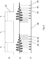
- Figure 5 shows that after switching off the high-voltage generator 14 - recognizable by the drop in the switch-on signal 50; please refer Figure 5a ) - post-oscillations still occur in the current curve 52 and the voltage curve 54 (see Figure 5b ), which lead to further registered zero crossings and thus to the pulsing 60 in the course of the pulsed DC voltage signal 56 (see FIG Figure 5c ). If the pulsed DC voltage signal 56 is low-pass filtered over a longer period of time, the amount of the resulting, smoothed DC voltage signal also depends on the pulses 60 caused by post-oscillations. If these were not available, the amount of the low-pass filtered, smoothed DC voltage signal would be lower.
- the result is an amount and thus an output signal of the phase shift determination unit due to the pulses 60 caused by post-oscillation, which does not correctly reflect the phase shift between current and voltage, but rather is falsified by the pulses 60 based on post-oscillation.
- the switching unit 36 namely the AND gate 36, is provided in the phase shift determining unit 26, which in fact suppresses the pulses 60 caused by post-oscillation.
- Figure 6 shows the course of the pulsed DC voltage 56, as it results when no switching unit 36 is provided.
- Figure 7 shows that the pulses 60 are masked out by the switching unit 36. Will that be in Figure 7
- the pulsed DC voltage signal 56 shown in the lower line is low-pass filtered and the low-pass filtered value is multiplied by the reciprocal of the duty cycle of the switch-on signal 50, the resulting amount reflects the phase shift between the current curve 52 and the voltage curve 54 very precisely.
Landscapes
- Health & Medical Sciences (AREA)
- Surgery (AREA)
- Engineering & Computer Science (AREA)
- Life Sciences & Earth Sciences (AREA)
- Biomedical Technology (AREA)
- Molecular Biology (AREA)
- Nuclear Medicine, Radiotherapy & Molecular Imaging (AREA)
- Plasma & Fusion (AREA)
- Physics & Mathematics (AREA)
- Heart & Thoracic Surgery (AREA)
- Medical Informatics (AREA)
- Otolaryngology (AREA)
- Animal Behavior & Ethology (AREA)
- General Health & Medical Sciences (AREA)
- Public Health (AREA)
- Veterinary Medicine (AREA)
- Surgical Instruments (AREA)
- Inverter Devices (AREA)
Claims (9)
- Générateur (10) d'électrochirurgie ayant des bornes (16, 18) pour un instrument électrochirurgical et ayant un générateur (14) de haute tension, qui est relié électriquement aux bornes (16, 18) et qui est constitué pour, dans son état mis en circuit, produire et fournir, par les bornes (16, 18), un courant alternatif de haute fréquence, le générateur (10) d'électrochirurgie ayant une unité (22) de détermination de la puissance active, qui comprend une unité (26) de détermination du déphasage, laquelle est constituée pour fournir un signal (58) de sortie, qui représente un déphasage entre courant et tension d'un courant alternatif fourni en fonctionnement, l'unité (26) de détermination de déphasage étant constituée pour produire un signal (56) de tension continue puisée, dans lequel la largeur (B) d'impulsion reflète une différence dans le temps entre les passages par zéro du courant et de la tension - et ainsi le déphasage - et pour transformer le signal (56) de tension continue puisée, au moyen d'un filtre (34) passe-bas, en un signal de sortie de filtre passe-bas, dont la valeur dépend de la largeur (B) des impulsions du signal (56) de tension continue puisée,
caractérisé en ce qu'il est prévu une unité (36) de coupure, qui est montée et constituée de manière à n'appliquer, au filtre (34) passe-bas, la tension continue puisée, que si le générateur (14) de haute tension est mis en circuit, mais non si le générateur (14) de haute tension est mis hors circuit. - Générateur (10) d'électrochirurgie suivant la revendication 1, caractérisé en ce que l'unité (26) de détermination de déphasage a un détecteur (30, 32) de passage au point zéro, qui produit la tension (56) continue pulsée en fonction du déphasage et l'unité (36) de coupure est montée entre une sortie du détecteur de passage au point zéro et une entrée du filtre (34) passe-bas.
- Générateur (10) d'électrochirurgie suivant la revendication 1 ou 2, caractérisé en ce que l'unité de coupure est réalisée en porte (36) ET, dont une entrée est reliée à une sortie de l'unité (26) de détermination du déphasage et dont l'autre entrée reçoit, lorsque le générateur (14) de haute tension est à l'état mis en circuit, un signal d'entrée de générateur, et dont la sortie est reliée au filtre (34) passe-bas.
- Générateur (10) d'électrochirurgie suivant la revendication 2, caractérisé en ce que le détecteur de passage par zéro a deux comparateurs (30, 32), dont un premier comparateur (30) est constitué et monté de manière à comparer un signal de tension à un signal de zéro et à produire un signal de sortie, si une valeur instantanée de la tension est plus haute que le signal de zéro, tandis que le deuxième comparateur (32) est constitué et monté de manière à comparer un signal de zéro à un signal de courant et à produire un signal de sortie, si le signal de zéro est plus grand qu'une valeur instantanée du courant, les sorties des comparateurs étant reliées entre elles, de manière à ce que les deux comparateurs ne fournissent un signal de sortie combiné, comme signal (56) de sortie de détecteur de passage par zéro ayant une valeur au-dessus d'une valeur de seuil, que si la valeur instantanée de la tension est positive (donc plus haute que la valeur zéro) et si en même temps la valeur instantanée du courant est négative (donc plus petite que la valeur zéro) ; ou inversement.
- Générateur (10) d'électrochirurgie suivant au moins l'une des revendications 1 à 4, caractérisé en ce que le générateur (14) de haute tension est constitué pour fournir, par l'intermédiaire des bornes (16, 18), dans son état de fonctionnement, le courant alternatif de haute fréquence cadencé à un rapport cyclique D,
caractérisé en ce que l'unité (22) de détermination de puissance active est constituée pour multiplier la tension continue par une valeur 1/D de correction, qui dépend du rapport cyclique D, et pour fournir une tension continue corrigée, comme signal représentant le déphasage. - Générateur (10) d'électrochirurgie suivant la revendication 5, caractérisé en ce que la valeur de correction correspond à l'inverse 1/D du rapport cyclique D.
- Générateur (10) d'électrochirurgie suivant au moins l'une des revendications 1 à 6, caractérisé en ce que le générateur (10) d'électrochirurgie a une unité (20) de commande, qui est reliée au générateur (14) de haute tension et qui commande celui-ci en fonctionnement.
- Générateur (10) d'électrochirurgie suivant la revendication 7, caractérisé en ce que l'unité (20) de commande est reliée à l'unité (22) de détermination de puissance active et est constituée pour recevoir, de l'unité (22) de détermination de puissance active, un signal de sortie, qui dépend du déphasage entre courant et tension du courant alternatif de haute fréquence fourni par le générateur (10) d'électrochirurgie en fonctionnement.
- Générateur (10) d'électrochirurgie suivant la revendication 7 ou 8, caractérisé en ce que l'unité (20) de commande est reliée à l'unité (22) de détermination de puissance active et est constituée pour fournir au circuit de commande un signal représentant le rapport cyclique D.
Applications Claiming Priority (2)
| Application Number | Priority Date | Filing Date | Title |
|---|---|---|---|
| DE102017112684.8A DE102017112684A1 (de) | 2017-06-08 | 2017-06-08 | Elektrochirurgie-Generator |
| PCT/EP2018/064929 WO2018224564A1 (fr) | 2017-06-08 | 2018-06-06 | Générateur électrochirurgical |
Publications (2)
| Publication Number | Publication Date |
|---|---|
| EP3634283A1 EP3634283A1 (fr) | 2020-04-15 |
| EP3634283B1 true EP3634283B1 (fr) | 2020-12-09 |
Family
ID=62563149
Family Applications (1)
| Application Number | Title | Priority Date | Filing Date |
|---|---|---|---|
| EP18729950.8A Active EP3634283B1 (fr) | 2017-06-08 | 2018-06-06 | Générateur électrochirurgical |
Country Status (6)
| Country | Link |
|---|---|
| US (1) | US11478293B2 (fr) |
| EP (1) | EP3634283B1 (fr) |
| JP (1) | JP7155163B2 (fr) |
| CN (1) | CN110603001B (fr) |
| DE (1) | DE102017112684A1 (fr) |
| WO (1) | WO2018224564A1 (fr) |
Families Citing this family (1)
| Publication number | Priority date | Publication date | Assignee | Title |
|---|---|---|---|---|
| CN110740702B (zh) * | 2017-06-15 | 2022-08-26 | 天津瑞奇外科器械股份有限公司 | 电外科系统和方法 |
Family Cites Families (15)
| Publication number | Priority date | Publication date | Assignee | Title |
|---|---|---|---|---|
| GB2027295B (en) * | 1978-07-31 | 1982-07-07 | Pye Ltd | Phrase comparator |
| DE19714972C2 (de) * | 1997-04-10 | 2001-12-06 | Storz Endoskop Gmbh Schaffhaus | Einrichtung zur Überwachung der Applikation einer Neutralelektrode |
| US20060126240A1 (en) * | 2004-12-10 | 2006-06-15 | Xantrex International | AC power backfeed protection based on voltage |
| DE102007051097A1 (de) | 2007-10-24 | 2009-04-30 | Celon Ag Medical Instruments | HF-Chirurgiegerät und Verfahren für ein HF-Chirurgiegerät |
| US8409186B2 (en) * | 2008-03-13 | 2013-04-02 | Covidien Lp | Crest factor enhancement in electrosurgical generators |
| FR2952197B1 (fr) * | 2009-10-29 | 2012-08-31 | Commissariat Energie Atomique | Dispositif de generation de signaux d'horloge a comparaison asymetrique d'erreurs de phase |
| KR20130108067A (ko) | 2010-04-09 | 2013-10-02 | 베식스 바스큘라 인코포레이티드 | 조직 치료를 위한 발전 및 제어 장치 |
| DE102010040824B4 (de) * | 2010-09-15 | 2015-12-31 | Olympus Winter & Ibe Gmbh | Hochfrequenz-Chirurgiegerät |
| DE102011078452A1 (de) | 2011-06-30 | 2013-01-03 | Robert Bosch Gmbh | Verfahren zum Ansteuern eines Wechselrichters eines Elektrowerkzeuges und Elektrowerkzeug |
| US9559594B2 (en) * | 2013-06-24 | 2017-01-31 | Covidien Lp | Dead-time optimization of resonant inverters |
| US9642670B2 (en) * | 2013-10-29 | 2017-05-09 | Covidien Lp | Resonant inverter with a common mode choke |
| US9901386B2 (en) * | 2014-01-13 | 2018-02-27 | Covidien Lp | Systems and methods for multifrequency cable compensation |
| US9554854B2 (en) * | 2014-03-18 | 2017-01-31 | Ethicon Endo-Surgery, Llc | Detecting short circuits in electrosurgical medical devices |
| ES2945708T3 (es) * | 2014-05-16 | 2023-07-06 | Applied Med Resources | Sistema electroquirúrgico |
| DE102015204127A1 (de) | 2015-03-06 | 2016-09-08 | Olympus Winter & Ibe Gmbh | Elektrochirurgie-Generator |
-
2017
- 2017-06-08 DE DE102017112684.8A patent/DE102017112684A1/de not_active Ceased
-
2018
- 2018-06-06 CN CN201880029442.5A patent/CN110603001B/zh active Active
- 2018-06-06 JP JP2019565920A patent/JP7155163B2/ja active Active
- 2018-06-06 EP EP18729950.8A patent/EP3634283B1/fr active Active
- 2018-06-06 WO PCT/EP2018/064929 patent/WO2018224564A1/fr not_active Ceased
- 2018-06-06 US US16/617,401 patent/US11478293B2/en active Active
Non-Patent Citations (1)
| Title |
|---|
| None * |
Also Published As
| Publication number | Publication date |
|---|---|
| EP3634283A1 (fr) | 2020-04-15 |
| DE102017112684A1 (de) | 2018-12-13 |
| US11478293B2 (en) | 2022-10-25 |
| WO2018224564A1 (fr) | 2018-12-13 |
| JP2020522311A (ja) | 2020-07-30 |
| US20200085488A1 (en) | 2020-03-19 |
| CN110603001A (zh) | 2019-12-20 |
| CN110603001B (zh) | 2022-11-11 |
| JP7155163B2 (ja) | 2022-10-18 |
Similar Documents
| Publication | Publication Date | Title |
|---|---|---|
| EP0709065B1 (fr) | Electrobistouri et méthode d'utilisation | |
| DE3531576C2 (de) | Elektrochirurgiegenerator | |
| DE3119735C2 (de) | Verfahren zur Regelung der Ausgangsleistung eines Hochfrequenz-Chirurgie-Generators | |
| EP0253012B1 (fr) | Appareil chirurgical à haute fréquence pour la coagulation thermique de tissus biologiques | |
| DE3544443C2 (de) | HF-Chirurgiegerät | |
| EP2044900B1 (fr) | Instrument d'électrochirurgie | |
| EP1399079B1 (fr) | Dispositif electrochirurgical | |
| EP0390937B1 (fr) | Dispositif pour surveiller l'adhésion des électrodes neutres utilisées en chirurgie à haute fréquence | |
| DE3510586A1 (de) | Kontrolleinrichtung fuer ein hochfrequenz-chirurgiegeraet | |
| EP0219568B1 (fr) | Appareil électrochirurgical à haute fréquence | |
| EP0925761A1 (fr) | Méthode pour l'utilisation d'un dispositif d'ablation de tissus et dispositif à haute fréquence pour cette méthode | |
| DE102007051097A1 (de) | HF-Chirurgiegerät und Verfahren für ein HF-Chirurgiegerät | |
| DE2901153A1 (de) | Elektrochirurgischer generator | |
| DE2140832A1 (de) | Verfahren und vorrichtung fuer die elektrische hochfrequenzchirurgie | |
| DE102004054575A1 (de) | Regelung für ein HF-Chirurgiegerät | |
| EP3132765A1 (fr) | Instrument de coagulation et de dissection a commande amelioree | |
| EP3634283B1 (fr) | Générateur électrochirurgical | |
| WO2024083961A1 (fr) | Dispositif électrochirurgical, système et procédé de commande d'un dispositif électrochirurgical | |
| DE2143562C3 (de) | Interferenzstromtherapiegerät | |
| DE102016220157A1 (de) | Hochfrequenzgenerator | |
| DE102020128589B4 (de) | Elektrochirurgie-Generator mit Wechselrichter zur Erzeugung von HF-Hochspannung | |
| EP2676624B1 (fr) | Appareil chirurgical haute fréquence | |
| DE20014128U1 (de) | Hochfrequenz-Chirurgiegerät | |
| DE102008050242B4 (de) | Hochfrequenz-Chirurgiegerät | |
| DE102024110877B3 (de) | Energieversorgungsvorrichtung |
Legal Events
| Date | Code | Title | Description |
|---|---|---|---|
| STAA | Information on the status of an ep patent application or granted ep patent |
Free format text: STATUS: UNKNOWN |
|
| STAA | Information on the status of an ep patent application or granted ep patent |
Free format text: STATUS: THE INTERNATIONAL PUBLICATION HAS BEEN MADE |
|
| PUAI | Public reference made under article 153(3) epc to a published international application that has entered the european phase |
Free format text: ORIGINAL CODE: 0009012 |
|
| STAA | Information on the status of an ep patent application or granted ep patent |
Free format text: STATUS: REQUEST FOR EXAMINATION WAS MADE |
|
| 17P | Request for examination filed |
Effective date: 20200108 |
|
| AK | Designated contracting states |
Kind code of ref document: A1 Designated state(s): AL AT BE BG CH CY CZ DE DK EE ES FI FR GB GR HR HU IE IS IT LI LT LU LV MC MK MT NL NO PL PT RO RS SE SI SK SM TR |
|
| AX | Request for extension of the european patent |
Extension state: BA ME |
|
| GRAP | Despatch of communication of intention to grant a patent |
Free format text: ORIGINAL CODE: EPIDOSNIGR1 |
|
| STAA | Information on the status of an ep patent application or granted ep patent |
Free format text: STATUS: GRANT OF PATENT IS INTENDED |
|
| DAV | Request for validation of the european patent (deleted) | ||
| DAX | Request for extension of the european patent (deleted) | ||
| INTG | Intention to grant announced |
Effective date: 20200623 |
|
| GRAS | Grant fee paid |
Free format text: ORIGINAL CODE: EPIDOSNIGR3 |
|
| GRAA | (expected) grant |
Free format text: ORIGINAL CODE: 0009210 |
|
| STAA | Information on the status of an ep patent application or granted ep patent |
Free format text: STATUS: THE PATENT HAS BEEN GRANTED |
|
| AK | Designated contracting states |
Kind code of ref document: B1 Designated state(s): AL AT BE BG CH CY CZ DE DK EE ES FI FR GB GR HR HU IE IS IT LI LT LU LV MC MK MT NL NO PL PT RO RS SE SI SK SM TR |
|
| REG | Reference to a national code |
Ref country code: GB Ref legal event code: FG4D Free format text: NOT ENGLISH |
|
| REG | Reference to a national code |
Ref country code: AT Ref legal event code: REF Ref document number: 1342574 Country of ref document: AT Kind code of ref document: T Effective date: 20201215 Ref country code: CH Ref legal event code: EP |
|
| REG | Reference to a national code |
Ref country code: DE Ref legal event code: R096 Ref document number: 502018003278 Country of ref document: DE |
|
| REG | Reference to a national code |
Ref country code: IE Ref legal event code: FG4D Free format text: LANGUAGE OF EP DOCUMENT: GERMAN |
|
| PG25 | Lapsed in a contracting state [announced via postgrant information from national office to epo] |
Ref country code: FI Free format text: LAPSE BECAUSE OF FAILURE TO SUBMIT A TRANSLATION OF THE DESCRIPTION OR TO PAY THE FEE WITHIN THE PRESCRIBED TIME-LIMIT Effective date: 20201209 Ref country code: RS Free format text: LAPSE BECAUSE OF FAILURE TO SUBMIT A TRANSLATION OF THE DESCRIPTION OR TO PAY THE FEE WITHIN THE PRESCRIBED TIME-LIMIT Effective date: 20201209 Ref country code: NO Free format text: LAPSE BECAUSE OF FAILURE TO SUBMIT A TRANSLATION OF THE DESCRIPTION OR TO PAY THE FEE WITHIN THE PRESCRIBED TIME-LIMIT Effective date: 20210309 Ref country code: GR Free format text: LAPSE BECAUSE OF FAILURE TO SUBMIT A TRANSLATION OF THE DESCRIPTION OR TO PAY THE FEE WITHIN THE PRESCRIBED TIME-LIMIT Effective date: 20210310 |
|
| PG25 | Lapsed in a contracting state [announced via postgrant information from national office to epo] |
Ref country code: SE Free format text: LAPSE BECAUSE OF FAILURE TO SUBMIT A TRANSLATION OF THE DESCRIPTION OR TO PAY THE FEE WITHIN THE PRESCRIBED TIME-LIMIT Effective date: 20201209 Ref country code: LV Free format text: LAPSE BECAUSE OF FAILURE TO SUBMIT A TRANSLATION OF THE DESCRIPTION OR TO PAY THE FEE WITHIN THE PRESCRIBED TIME-LIMIT Effective date: 20201209 Ref country code: BG Free format text: LAPSE BECAUSE OF FAILURE TO SUBMIT A TRANSLATION OF THE DESCRIPTION OR TO PAY THE FEE WITHIN THE PRESCRIBED TIME-LIMIT Effective date: 20210309 |
|
| REG | Reference to a national code |
Ref country code: NL Ref legal event code: MP Effective date: 20201209 |
|
| PG25 | Lapsed in a contracting state [announced via postgrant information from national office to epo] |
Ref country code: NL Free format text: LAPSE BECAUSE OF FAILURE TO SUBMIT A TRANSLATION OF THE DESCRIPTION OR TO PAY THE FEE WITHIN THE PRESCRIBED TIME-LIMIT Effective date: 20201209 Ref country code: HR Free format text: LAPSE BECAUSE OF FAILURE TO SUBMIT A TRANSLATION OF THE DESCRIPTION OR TO PAY THE FEE WITHIN THE PRESCRIBED TIME-LIMIT Effective date: 20201209 |
|
| REG | Reference to a national code |
Ref country code: LT Ref legal event code: MG9D |
|
| PG25 | Lapsed in a contracting state [announced via postgrant information from national office to epo] |
Ref country code: SK Free format text: LAPSE BECAUSE OF FAILURE TO SUBMIT A TRANSLATION OF THE DESCRIPTION OR TO PAY THE FEE WITHIN THE PRESCRIBED TIME-LIMIT Effective date: 20201209 Ref country code: SM Free format text: LAPSE BECAUSE OF FAILURE TO SUBMIT A TRANSLATION OF THE DESCRIPTION OR TO PAY THE FEE WITHIN THE PRESCRIBED TIME-LIMIT Effective date: 20201209 Ref country code: EE Free format text: LAPSE BECAUSE OF FAILURE TO SUBMIT A TRANSLATION OF THE DESCRIPTION OR TO PAY THE FEE WITHIN THE PRESCRIBED TIME-LIMIT Effective date: 20201209 Ref country code: CZ Free format text: LAPSE BECAUSE OF FAILURE TO SUBMIT A TRANSLATION OF THE DESCRIPTION OR TO PAY THE FEE WITHIN THE PRESCRIBED TIME-LIMIT Effective date: 20201209 Ref country code: LT Free format text: LAPSE BECAUSE OF FAILURE TO SUBMIT A TRANSLATION OF THE DESCRIPTION OR TO PAY THE FEE WITHIN THE PRESCRIBED TIME-LIMIT Effective date: 20201209 Ref country code: RO Free format text: LAPSE BECAUSE OF FAILURE TO SUBMIT A TRANSLATION OF THE DESCRIPTION OR TO PAY THE FEE WITHIN THE PRESCRIBED TIME-LIMIT Effective date: 20201209 Ref country code: PT Free format text: LAPSE BECAUSE OF FAILURE TO SUBMIT A TRANSLATION OF THE DESCRIPTION OR TO PAY THE FEE WITHIN THE PRESCRIBED TIME-LIMIT Effective date: 20210409 |
|
| PG25 | Lapsed in a contracting state [announced via postgrant information from national office to epo] |
Ref country code: PL Free format text: LAPSE BECAUSE OF FAILURE TO SUBMIT A TRANSLATION OF THE DESCRIPTION OR TO PAY THE FEE WITHIN THE PRESCRIBED TIME-LIMIT Effective date: 20201209 |
|
| REG | Reference to a national code |
Ref country code: DE Ref legal event code: R097 Ref document number: 502018003278 Country of ref document: DE |
|
| PG25 | Lapsed in a contracting state [announced via postgrant information from national office to epo] |
Ref country code: IS Free format text: LAPSE BECAUSE OF FAILURE TO SUBMIT A TRANSLATION OF THE DESCRIPTION OR TO PAY THE FEE WITHIN THE PRESCRIBED TIME-LIMIT Effective date: 20210409 |
|
| PLBE | No opposition filed within time limit |
Free format text: ORIGINAL CODE: 0009261 |
|
| STAA | Information on the status of an ep patent application or granted ep patent |
Free format text: STATUS: NO OPPOSITION FILED WITHIN TIME LIMIT |
|
| PG25 | Lapsed in a contracting state [announced via postgrant information from national office to epo] |
Ref country code: AL Free format text: LAPSE BECAUSE OF FAILURE TO SUBMIT A TRANSLATION OF THE DESCRIPTION OR TO PAY THE FEE WITHIN THE PRESCRIBED TIME-LIMIT Effective date: 20201209 Ref country code: IT Free format text: LAPSE BECAUSE OF FAILURE TO SUBMIT A TRANSLATION OF THE DESCRIPTION OR TO PAY THE FEE WITHIN THE PRESCRIBED TIME-LIMIT Effective date: 20201209 |
|
| 26N | No opposition filed |
Effective date: 20210910 |
|
| PG25 | Lapsed in a contracting state [announced via postgrant information from national office to epo] |
Ref country code: DK Free format text: LAPSE BECAUSE OF FAILURE TO SUBMIT A TRANSLATION OF THE DESCRIPTION OR TO PAY THE FEE WITHIN THE PRESCRIBED TIME-LIMIT Effective date: 20201209 Ref country code: SI Free format text: LAPSE BECAUSE OF FAILURE TO SUBMIT A TRANSLATION OF THE DESCRIPTION OR TO PAY THE FEE WITHIN THE PRESCRIBED TIME-LIMIT Effective date: 20201209 |
|
| PG25 | Lapsed in a contracting state [announced via postgrant information from national office to epo] |
Ref country code: ES Free format text: LAPSE BECAUSE OF FAILURE TO SUBMIT A TRANSLATION OF THE DESCRIPTION OR TO PAY THE FEE WITHIN THE PRESCRIBED TIME-LIMIT Effective date: 20201209 Ref country code: MC Free format text: LAPSE BECAUSE OF FAILURE TO SUBMIT A TRANSLATION OF THE DESCRIPTION OR TO PAY THE FEE WITHIN THE PRESCRIBED TIME-LIMIT Effective date: 20201209 |
|
| REG | Reference to a national code |
Ref country code: CH Ref legal event code: PL |
|
| REG | Reference to a national code |
Ref country code: BE Ref legal event code: MM Effective date: 20210630 |
|
| PG25 | Lapsed in a contracting state [announced via postgrant information from national office to epo] |
Ref country code: LU Free format text: LAPSE BECAUSE OF NON-PAYMENT OF DUE FEES Effective date: 20210606 |
|
| PG25 | Lapsed in a contracting state [announced via postgrant information from national office to epo] |
Ref country code: LI Free format text: LAPSE BECAUSE OF NON-PAYMENT OF DUE FEES Effective date: 20210630 Ref country code: IE Free format text: LAPSE BECAUSE OF NON-PAYMENT OF DUE FEES Effective date: 20210606 Ref country code: CH Free format text: LAPSE BECAUSE OF NON-PAYMENT OF DUE FEES Effective date: 20210630 |
|
| PG25 | Lapsed in a contracting state [announced via postgrant information from national office to epo] |
Ref country code: IS Free format text: LAPSE BECAUSE OF FAILURE TO SUBMIT A TRANSLATION OF THE DESCRIPTION OR TO PAY THE FEE WITHIN THE PRESCRIBED TIME-LIMIT Effective date: 20210409 Ref country code: FR Free format text: LAPSE BECAUSE OF NON-PAYMENT OF DUE FEES Effective date: 20210630 |
|
| PG25 | Lapsed in a contracting state [announced via postgrant information from national office to epo] |
Ref country code: BE Free format text: LAPSE BECAUSE OF NON-PAYMENT OF DUE FEES Effective date: 20210630 |
|
| P01 | Opt-out of the competence of the unified patent court (upc) registered |
Effective date: 20230519 |
|
| PG25 | Lapsed in a contracting state [announced via postgrant information from national office to epo] |
Ref country code: CY Free format text: LAPSE BECAUSE OF FAILURE TO SUBMIT A TRANSLATION OF THE DESCRIPTION OR TO PAY THE FEE WITHIN THE PRESCRIBED TIME-LIMIT Effective date: 20201209 |
|
| PG25 | Lapsed in a contracting state [announced via postgrant information from national office to epo] |
Ref country code: HU Free format text: LAPSE BECAUSE OF FAILURE TO SUBMIT A TRANSLATION OF THE DESCRIPTION OR TO PAY THE FEE WITHIN THE PRESCRIBED TIME-LIMIT; INVALID AB INITIO Effective date: 20180606 |
|
| PG25 | Lapsed in a contracting state [announced via postgrant information from national office to epo] |
Ref country code: MK Free format text: LAPSE BECAUSE OF FAILURE TO SUBMIT A TRANSLATION OF THE DESCRIPTION OR TO PAY THE FEE WITHIN THE PRESCRIBED TIME-LIMIT Effective date: 20201209 |
|
| PG25 | Lapsed in a contracting state [announced via postgrant information from national office to epo] |
Ref country code: TR Free format text: LAPSE BECAUSE OF FAILURE TO SUBMIT A TRANSLATION OF THE DESCRIPTION OR TO PAY THE FEE WITHIN THE PRESCRIBED TIME-LIMIT Effective date: 20201209 |
|
| REG | Reference to a national code |
Ref country code: AT Ref legal event code: MM01 Ref document number: 1342574 Country of ref document: AT Kind code of ref document: T Effective date: 20230606 |
|
| PG25 | Lapsed in a contracting state [announced via postgrant information from national office to epo] |
Ref country code: MT Free format text: LAPSE BECAUSE OF FAILURE TO SUBMIT A TRANSLATION OF THE DESCRIPTION OR TO PAY THE FEE WITHIN THE PRESCRIBED TIME-LIMIT Effective date: 20201209 |
|
| PG25 | Lapsed in a contracting state [announced via postgrant information from national office to epo] |
Ref country code: AT Free format text: LAPSE BECAUSE OF NON-PAYMENT OF DUE FEES Effective date: 20230606 |
|
| PG25 | Lapsed in a contracting state [announced via postgrant information from national office to epo] |
Ref country code: AT Free format text: LAPSE BECAUSE OF NON-PAYMENT OF DUE FEES Effective date: 20230606 |
|
| PGFP | Annual fee paid to national office [announced via postgrant information from national office to epo] |
Ref country code: DE Payment date: 20250429 Year of fee payment: 8 |
|
| PGFP | Annual fee paid to national office [announced via postgrant information from national office to epo] |
Ref country code: GB Payment date: 20250501 Year of fee payment: 8 |
|
| PGFP | Annual fee paid to national office [announced via postgrant information from national office to epo] |
Ref country code: AT Payment date: 20260410 Year of fee payment: 5 |
|
| REG | Reference to a national code |
Ref country code: DE Ref legal event code: R082 Ref document number: 502018003278 Country of ref document: DE Representative=s name: EISENFUEHR SPEISER PATENTANWAELTE RECHTSANWAEL, DE |