EP3635244B1 - Rotorblatt für eine windenergieanlage und windenergieanlage - Google Patents
Rotorblatt für eine windenergieanlage und windenergieanlage Download PDFInfo
- Publication number
- EP3635244B1 EP3635244B1 EP18722540.4A EP18722540A EP3635244B1 EP 3635244 B1 EP3635244 B1 EP 3635244B1 EP 18722540 A EP18722540 A EP 18722540A EP 3635244 B1 EP3635244 B1 EP 3635244B1
- Authority
- EP
- European Patent Office
- Prior art keywords
- rotor blade
- section
- trailing edge
- blade
- segment
- Prior art date
- Legal status (The legal status is an assumption and is not a legal conclusion. Google has not performed a legal analysis and makes no representation as to the accuracy of the status listed.)
- Active
Links
Images


Classifications
-
- F—MECHANICAL ENGINEERING; LIGHTING; HEATING; WEAPONS; BLASTING
- F03—MACHINES OR ENGINES FOR LIQUIDS; WIND, SPRING, OR WEIGHT MOTORS; PRODUCING MECHANICAL POWER OR A REACTIVE PROPULSIVE THRUST, NOT OTHERWISE PROVIDED FOR
- F03D—WIND MOTORS
- F03D1/00—Wind motors with rotation axis substantially parallel to the air flow entering the rotor
- F03D1/06—Rotors
- F03D1/0608—Rotors characterised by their aerodynamic shape
- F03D1/0633—Rotors characterised by their aerodynamic shape of the blades
- F03D1/0641—Rotors characterised by their aerodynamic shape of the blades of the section profile of the blades, i.e. aerofoil profile
-
- F—MECHANICAL ENGINEERING; LIGHTING; HEATING; WEAPONS; BLASTING
- F03—MACHINES OR ENGINES FOR LIQUIDS; WIND, SPRING, OR WEIGHT MOTORS; PRODUCING MECHANICAL POWER OR A REACTIVE PROPULSIVE THRUST, NOT OTHERWISE PROVIDED FOR
- F03D—WIND MOTORS
- F03D1/00—Wind motors with rotation axis substantially parallel to the air flow entering the rotor
- F03D1/06—Rotors
- F03D1/065—Rotors characterised by their construction elements
- F03D1/0675—Rotors characterised by their construction elements of the blades
-
- F—MECHANICAL ENGINEERING; LIGHTING; HEATING; WEAPONS; BLASTING
- F05—INDEXING SCHEMES RELATING TO ENGINES OR PUMPS IN VARIOUS SUBCLASSES OF CLASSES F01-F04
- F05B—INDEXING SCHEME RELATING TO WIND, SPRING, WEIGHT, INERTIA OR LIKE MOTORS, TO MACHINES OR ENGINES FOR LIQUIDS COVERED BY SUBCLASSES F03B, F03D AND F03G
- F05B2240/00—Components
- F05B2240/20—Rotors
- F05B2240/30—Characteristics of rotor blades, i.e. of any element transforming dynamic fluid energy to or from rotational energy and being attached to a rotor
-
- Y—GENERAL TAGGING OF NEW TECHNOLOGICAL DEVELOPMENTS; GENERAL TAGGING OF CROSS-SECTIONAL TECHNOLOGIES SPANNING OVER SEVERAL SECTIONS OF THE IPC; TECHNICAL SUBJECTS COVERED BY FORMER USPC CROSS-REFERENCE ART COLLECTIONS [XRACs] AND DIGESTS
- Y02—TECHNOLOGIES OR APPLICATIONS FOR MITIGATION OR ADAPTATION AGAINST CLIMATE CHANGE
- Y02E—REDUCTION OF GREENHOUSE GAS [GHG] EMISSIONS, RELATED TO ENERGY GENERATION, TRANSMISSION OR DISTRIBUTION
- Y02E10/00—Energy generation through renewable energy sources
- Y02E10/70—Wind energy
- Y02E10/72—Wind turbines with rotation axis in wind direction
Definitions
- the invention relates to a rotor blade for a wind turbine, with an inner blade section, which extends from a rotor blade root in the longitudinal direction of the rotor blade, a trailing edge segment arranged on the inner blade section to increase the profile depth of the rotor blade along a section in the longitudinal direction of the rotor blade, the rotor blade a pressure side surface and a suction side surface each formed in regions from portions of the inner blade portion and the trailing edge segment. Furthermore, the invention relates to a wind energy plant with a tower, a nacelle and a rotor, as well as a wind farm.
- the profile depth which is understood below to mean the length of the profile essentially perpendicular to the longitudinal direction of the rotor blade, ie the distance between a profile nose and a profile trailing edge of the rotor blade, should be as large as possible for this purpose.
- the rotor blade root describes the area of the rotor blade with which the rotor blade is attached to the rotor hub of the wind turbine.
- the maximum profile depth in such a rotor blade is often very close to the rotor blade root. This reduces the generation of vortices and increases the efficiency of the wind turbine. For example, due to transport restrictions, the maximum tread depth is limited.
- Another way to increase efficiency is to influence the boundary layer, which is becoming more and more important due to the increasing profile depths.
- the air flow runs against a pressure gradient after passing the maximum curvature in the rear area of the rotor blade profile. This causes the air flow to slow down, causing the boundary layer to lose kinetic energy.
- the slowing down of the air flow means that the boundary layer begins to detach from the surface of the rotor blade.
- a flow separated from the rotor blade surface results in turbulence, which reduces the lift produced on the suction side and thus increases drag.
- WO 2014/064626 A2 discloses an aerodynamic approach for a wind turbine rotor blade that is designed to fit the inner portion and the intermediate portion of the wind turbine rotor blade and has a trailing edge on the pressure side, a suction side, and at least one channel fluidly connecting the pressure side to the suction side .
- DE 10 2014 205 016 A1 relates to a rotor blade of a wind turbine with a rotor, which in particular has a substantially horizontal axis of rotation, the rotor blade having a rotor blade shell with a suction side and a pressure side and extending from a root-side end to a rotor blade tip, the rotor blade also having a profile, the profile defining a chord extending from a leading edge of the blade to a trailing edge of the blade.
- the rotor blade is characterized in that a closable airflow device is provided, which provides a closure element in the rotor blade shell, the closure element being or being opened to provide a supplementary airflow to an airflow prevailing on the suction side and/or pressure side.
- DE 10 2011 056 108 A1 describes a wind turbine blade that includes a permeable window defined in the suction side.
- the transmissive window contains a plurality of holes defined within it.
- An air diffuser in the interior cavity of the blade communicates with the permeable windows in airflow connection.
- An intake air duct in the pressure side of the blade communicates with the air manifold.
- a slidable cover member is configured adjacent to the permeable window and is variable from a fully closed position in which airflow through the permeable window perforations is blocked to a fully open position in which airflow through the permeable window perforations is established , moveable.
- U.S. 2016/0177922 A1 describes trailing edge nozzles on a wind turbine rotor blade for noise reduction, wherein one or more air nozzles produce respective jets of air angled radially from a blunt trailing edge of a wind turbine rotor blade.
- the jets create and maintain a radially flowing airflow along the trailing edge that quenches vortex shedding. This reduces drag and noise, which allows the blades to have an extensive blunt trailing edge, increasing resistance to buckling and thus allowing for longer blades.
- the jets may be provided by air flow from an air intake in a rotor blade compartment or a ram air intake or a compressor.
- Each nozzle can be metered individually and/or individually or as a group valve to provide a specific air flow to each nozzle relative to the other nozzles.
- the total airflow to the nozzles may be modulated in response to ambient conditions and may further be cyclically modulated in response to an azimuth angle of the rotor blade
- U.S. 2011/0206507 A1 describes an air distribution system for manipulating an air boundary layer over a rotor blade of a wind turbine.
- the wind turbine rotor blade includes at least one sidewall that defines a cavity therein.
- the sidewall extends between a leading edge and an axially spaced trailing edge and defines a chord axis between the leading edge and the trailing edge.
- the air distribution system includes a plurality of bleed flow arrangements positioned within the rotor blade and configured to vent air into the boundary layer to reduce separation of the boundary layer from the rotor blade.
- Each vent flow assembly of the plurality of vent flow assemblies includes a vent flow conduit coupled to an inner surface of the sidewall and oriented with respect to the chord axis between the leading edge and the trailing edge.
- the vent line is configured to direct air through the rotor blade.
- An inlet opening is defined by the vent line and by the sidewall to direct air into the vent line.
- US 2011/0142638 A1 describes a rotor blade of a wind turbine, which comprises a pressure side and a suction side. At least one airfoil passage is defined by the blade between the pressure side and the suction side. A corresponding cover is configured over the airfoil passage on each pressure and suction side. The covers are operable between a closed position, in which the cover is flush with the respective pressure or suction side, and an open position, in which the cover moves to open the airfoil channel.
- the invention is based on the object of improving a rotor blade of the aforementioned type in such a way that a simplified and more efficient boundary layer influencing is achieved.
- the object on which the invention is based is achieved in the case of a rotor blade for a wind energy installation with the features according to claim 1 .
- at least one air inlet and air outlet are formed on the pressure-side surface and on the suction-side surface of the rotor blade in the area of the trailing edge segment overlapping cover element is arranged, through which the at least one air outlet can be closed or released.
- the invention makes use of the knowledge that with the help of an air inlet and air outlet, in particular a slot-like air inlet and outlet, is formed on the pressure-side and suction-side surface of the rotor blade, at least one suction and blow-out area is formed with which a boundary layer flowing in the direction of the profile depth of the rotor blade advantageously being affected.
- the air flowing out of the air outlet contributes to increasing the kinetic energy in the boundary layer flow. This contributes to overcoming the pressure increase after passing the maximum curvature in the rear area of the rotor blade profile. It is particularly advantageous that the blowing out takes place by passive actuation of the cover element. When the boundary layer flow begins to separate on the suction-side surface of the rotor blade, the cover element releases the air outlet.
- the cover element prevents an aerodynamic short circuit due to the fluid-conducting coupling of the air inlet and air outlet arranged on the opposite sides of the rotor blade.
- the fluid-conducting coupling creates an automatic air flow from the air inlet on the pressure side to the air outlet on the suction side of the rotor blade.
- the cover element prevents an uncontrolled Blow out or outflow, which would reduce lift and increase drag.
- the profile depth of the rotor blade in the rotor root area can be effectively increased by arranging at least one trailing edge segment.
- the extent of the at least one trailing edge segment is up to one third of the length of the rotor blade.
- Full profiling of this area of the rotor blade contributes significantly to the annual energy yield (AEP) of the wind turbine, cumulatively over the service life of the wind turbine, especially at low average speeds.
- AEP annual energy yield
- the inner blade section preferably has a round or oval profile section, which enables simple manufacture and attachment to the rotor hub. Through the trailing edge segment, an aerodynamic effect can also be achieved in this section, in which the profile section is round or oval.
- the air flow is influenced in the area of the rotor blade where it achieves the greatest effect, namely in the area where the boundary layer begins to detach. Furthermore, no drilling or structural changes are required on the inner blade section, which can cause stability problems.
- a slit-like air inlet and air outlet is a slit or gap in the surface of the rotor blade on its pressure-side and suction-side surface, the dimension of which is greater in the longitudinal direction of the rotor blade than in the direction of the profile depth.
- the dimensions of the air inlets and air outlets in the longitudinal direction of the rotor blade are preferably many times larger than in the direction of the profile depth.
- the blade longitudinal dimension is at least twice the chord dimension.
- the dimension in the longitudinal direction of the rotor blade is at least 10 times larger, in particular at least 20 times larger, particularly preferably at least 50 times larger than the dimension in the direction of the profile depth.
- the at least one air inlet and air outlet can be fluidly connected to one another by the trailing edge segment.
- the trailing edge segment adjoining the inner leaf section can form an enclosed space into which air flows through the air inlet.
- the at least one cover element can be actuated as a function of a dynamic pressure occurring inside the trailing edge segment.
- the at least one cover element is set up to deflect the air flow in the area of the air outlet essentially parallel to the respectively adjoining outer surface of the inner leaf section.
- the air flow is preferably discharged or blown out, preferably in the direction of the air flow flowing along the suction-side surface of the rotor blade. This influences the boundary layer on the suction-side surface of the rotor blade in a simplified manner.
- the at least one cover element has a first section, with which the at least one cover element is attached to the inner sheet section, and a second section, which overlaps the at least one air outlet.
- the first section used for fastening can have a surface which is adapted to the contour of the inner leaf section. In this way, disturbing influences on the air flow can be largely avoided.
- such a cover element can be installed in a simple manner.
- the second section can completely or partially overlap the air outlet in the longitudinal direction of the rotor blade.
- At least the second section of the at least one cover element can be designed to be flexible. This has the advantage that the closing and opening of the air outlet can be controlled depending on the spring stiffness of the material used to manufacture the cover element.
- the at least one cover element can be designed in two parts.
- the first section and the second section can be connected to one another at least in sections by a joint. Closing and releasing the air outlet can be influenced by the dead weight of the second section.
- the joint can be spring-loaded.
- each air inlet and air outlet is formed directly in the transition area from the inner blade section to the trailing edge segment.
- the upper side forming a region of the suction-side surface and the upper side forming a region of the pressure-side surface of the rotor blade Underside of the trailing edge segment are shortened toward the inner sheet portion in a simple manner. This creates an interruption in the suction-side and pressure-side surface of the rotor blade due to an edge on the upper and lower side of the trailing edge segment that is set back on the inner blade section.
- the edges of the upper and lower sides of the trailing edge segment are thus arranged at a distance from a respectively assigned area of the inner sheet section.
- the trailing edge segment can accordingly have a first edge and a second edge, which delimit the pressure-side and suction-side surfaces of the trailing edge segment.
- the first edge and the second edge are preferably substantially tangential to the surface of the inner sheet portion.
- the first and second edges are spaced from the inner panel portion such that the air inlet and the air outlet are formed therebetween.
- the distance between the first edge or the second edge and the inner sheet section can be designed differently.
- the distance of the first edge is preferably greater than the distance of the second edge to the inner sheet section.
- a wider gap forming the air inlet is formed on the pressure-side surface of the trailing edge segment. This leads to an increase in the volume flow or an increase in the outflow velocity at the air outlet.
- the trailing edge segment may have a leading edge portion which is arranged at the first edge and which partially extends in the circumferential direction of the inner sheet portion.
- the leading edge portion forms a gate for dynamic pressure recovery. This measure leads to an increase in the volume flow or outflow speed at the air outlet.
- One embodiment of the invention preferably provides that the trailing edge segment is formed from at least one contour element extending in sections in the circumferential direction of the inner blade section and at least one profile element arranged at an angle to the contour element on the suction-side surface.
- the profile element preferably has a curved profile.
- the contour element can be fastened by means of webs arranged on the surface of the inner leaf section at a radial distance from the latter.
- the contour element can be adapted to the outer shape of the inner sheet section.
- At least one flow channel is formed between the inner sheet section and the contour element, which fluidly connects the air inlet on the pressure-side surface to the air outlet on the suction-side surface.
- At least one connecting element can be arranged or formed between the contour element and the profile element. Depending on the configuration of the at least one connecting element, it can have different functions. The at least one connecting element can thus serve to keep the distance between the contour element and the profile element constant. In addition, the at least one connecting element can be used to influence the air flow in this area.
- the at least one connecting element can extend between the surface of the contour element and the underside of the profile element facing it.
- the at least one connecting element can have a substantially elongated shape, so that the at least one connecting element is only connected to the contour element and the profile element in the area of its outer ends.
- the connecting element can be designed, for example, in the form of a rod or rod.
- the at least one connecting element can be flat at least in the plane orthogonal to the contour element and the profile element and can have a polygonal outline. In this case, an outer edge of the connecting element facing the contour element or the profile element lies in linear contact.
- the connecting element can be in the form of a triangular web or a rib body.
- the at least one connecting element can be designed as a rose thorn profile. Due to such a mandrel widening, not only can the profile depth in the hub area be made advantageously small, but vortex shedding and thus the noise emission can also be advantageously influenced.
- the profile element can be designed as a surface segment that can be wound up by means of a winding device, which can be stretched over battens arranged on the contour element.
- the winding device is advantageously integrated into the trailing edge segment.
- the rollable design of the profile element has the advantage that transport is simplified due to reduced dimensions.
- the profile element which is designed as a surface segment, can be pulled out and stretched using the battens that define the contour.
- one or more rib bodies can be provided between the battens and the contour element.
- the rib body connected by means of a non-positive connection or a material connection with the correspondingly assigned surface areas of the battens and contour element.
- the invention also relates to a wind energy plant with a tower, a nacelle and a rotor.
- the invention also solves the problem on which the rotor blade according to the invention is based, in that a rotor blade connected to the rotor is designed according to one of the preferred embodiments of the invention described above. With such a rotor blade designed according to the invention, it is possible to influence the boundary layer on the rotor blade, as a result of which the efficiency of the wind energy installation can be improved in a simple manner.
- the invention also relates to a wind farm with a plurality of wind turbines, which are designed according to one of the preferred embodiments of the invention described above.
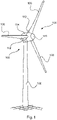
- figure 1 shows a wind turbine 100 with a tower 102 and a nacelle 104.
- a rotor 106 with three rotor blades 108 and a spinner 110 is arranged on the nacelle 104.
- the rotor blades 108 are arranged with their rotor blade roots on a rotor hub.
- the rotor 106 is rotated by the wind and thereby drives a generator (not shown) in the nacelle 104 .
- the rotor blades 108 each have a trailing edge segment 112, by means of which they are designed as flexible rotor blades.
- the at least one trailing edge segment 112 extends in sections, starting from the rotor blade root, in the longitudinal direction of the rotor blade 108.
- the extent of the at least one trailing edge segment 112 is up to one third of the length of the rotor blade 108.
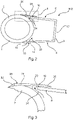
- In 2 1 is a sectional view of the rotor blade 108 in the rotor hub area with a trailing edge segment 112 according to a first exemplary embodiment.
- the rotor blade 108 shown has the trailing edge segment 112 extending the profile depth of the rotor blade 108 in an inner blade section 2 adjoining the rotor blade root 1 .
- the trailing edge segment 112 has a pressure side surface 4 and a suction side surface 6 .
- the trailing edge segment 112 is designed as a multi-part profile element and has a segment section 8 designed as a foot segment with a substantially U-shaped cross section.
- a rear surface 12 running essentially perpendicularly between the suction-side and pressure-side surfaces 4, 6 delimits the segment section 8 of the trailing edge segment 112.
- the rear surface 12 Opposite the rear surface 12 is an open connection side 10 on which the trailing edge segment 112 is attached to the inner panel section 2 of the rotor blade 108 is arranged.
- a first edge 14 and a second edge 16 run on the connecting side 10 of the trailing edge segment 112 and delimit the suction-side and pressure-side surfaces 4, 6 of the trailing edge segment 112.
- the first edge 14 and the second edge 16 are adapted to the curvature of the rotor blade 108 and run essentially in the longitudinal direction of the rotor blade.
- the first edge 14 and the second edge 16 extend tangentially to the lateral surface of the inner blade section 2 in the direction of the profile depth of the rotor blade 108.
- the rear surface 12 of the segment section 8 is in the assembled state on a rear edge, not shown, of the area adjoining the inner blade section 2 Rotor blade 108 aligned. At least one further segment section adjoins the rear surface 10 of the segment section 8 . The at least one further segment section forms part of the rear edge of rear edge segment 112.
- the first edge 14 of the trailing edge segment 112 ends at a distance from the outer surface or outer contour of the inner sheet section 2, as a result of which a first gap 18 is formed between the pressure-side surface 4 of the trailing edge segment 112 and the inner sheet section 2.
- the boundary layer on the pressure-side surface 4 of the rotor blade 108 can be sucked off through the first gap 18, which is formed in the transition area from the inner blade section 2 to the trailing edge segment 112.
- the first gap 18 forms an in particular slot-like air inlet 22 into the interior of the trailing edge segment 112 .
- the second edge 16 of the trailing edge segment 112 also ends at a distance from the outer surface or the outer contour of the inner sheet section 2, as a result of which a second gap 20 is formed between the pressure-side surface 4 of the trailing edge segment 112 and the inner sheet section 2 .
- the second gap 20 forms an air outlet 24 , in particular a slot-like one, from the interior of the trailing edge segment 112 .
- the first gap 18 and the second gap 20 are fluidly connected to one another by the essentially U-shaped segment section 8 .
- the air outlet 24 on the suction-side surface 6 of the trailing edge segment 112 is covered by at least one cover element 26 .
- the cover element 26 is arranged on the inner sheet section 2 and extends in sections over the suction-side Surface 6 of the trailing edge segment 112.
- the extension of the at least one cover element 26 in the longitudinal direction of the rotor blade 108 corresponds to the dimensions of the second gap 20 on the suction-side surface 6.
- the cover element 26 has a first section designed as a fastening section 28 .
- the air outlet 26 formed by the second gap 20 is overlapped by a second section of the covering element 26 designed as a covering section 30, as shown in the detailed view in FIG 3 is shown in more detail.
- the cover element 26 is designed as an essentially plate-shaped profile component.
- the free end of the fastening section 28 facing the inflow has a flattened transition to the surface of the inner leaf section 2 .
- a leading edge 32 designed as a separate element is provided in order to avoid turbulence in the transition between the surface of the inner leaf section 2 and the cover element 26 .
- the free end of the fastening section 28 can have a tapering course, or a flow-optimized transition is created by means of a balancing mass.
- the free end of the cover element 30 likewise has a tapering or flattening course.
- At least the second section, the covering section 30, of the covering element 26 is made from a flexible material.
- the depictions in the Figures 2 and 3 show the cover element 26 in a position resting against the surface of the segment section 8 . In the abutting position, the air outlet 24 is closed.
- FIG 4 is a detail view II according to FIG 2 shown in a second position of the cover element 26.
- the covering section 30 has been lifted by the dynamic pressure building up inside the segment section 8 and the detachment of the boundary layer flow on the suction-side surface 6, so that the air outlet 24 is released.
- the cover section 30 not only releases the air outlet 24 but also, due to its design, deflects the air flowing out through the air outlet 24 in such a way that it flows out in the flow direction of the air flow LS on the suction-side surface 6 .
- the boundary layer flow on the suction-side surface 6 is supplied with energy to overcome the pressure difference leading to flow separation.
- the cover section 30 of the cover element 26 forms a type of pressure relief valve.
- cover section 30 When a threshold value for the dynamic pressure inside segment section 8 is passed, cover section 30 temporarily moves from a position that closes barrel outlet 24 to a position that opens air outlet 24 position above.
- the threshold value of the dynamic pressure which leads to the opening or release of the air outlet 24, can be varied, among other things, by the flexural rigidity of the material used for the cover section 30.
- a further possibility is to make the fastening section 28, which is firmly connected to the surface of the inner sheet section 2, shorter, so that the lever arm of the cover section 30 is lengthened.
- the representation in figure 5 12 shows a second embodiment of a trailing edge segment 112'.
- the trailing edge segment 112' has a segment section 8' designed as a foot segment and having a substantially U-shaped cross section.
- a rear surface 12' running substantially perpendicularly between the suction-side and pressure-side surfaces 4, 6 delimits the segment portion 8' of the trailing edge segment 112'.
- a first edge 14' and a second edge 16' run on the connection side 10 of the trailing edge segment 112', which delimit the suction-side and pressure-side surfaces 4, 6 of the trailing edge segment 112'.
- This second exemplary embodiment differs in that the first edge 14′ has a front edge section 34 which has a course that is curved in sections.
- the front edge section 34 is designed to be extended in sections in the circumferential direction of the inner sheet section 2 .
- the leading edge section 34 partially overlaps the lateral surface of the inner sheet section 2 .
- the leading edge portion 34 is formed with a tapered tip to reduce turbulence. Due to the course of the first edge 14' in the direction of the profile depth of the rotor blade 108, which is adapted to the contour of the lateral surface of the inner blade section 2, the first gap 18' or air inlet 22 is enlarged. This has the effect of increasing the flow of air supplied into the interior of the segment portion 8'. As a result, a higher dynamic pressure can be built up inside the segment section 8'.
- the higher dynamic pressure in the segment section 8' that can be achieved by increasing the supplied air volume flow leads to a higher outflow speed through the air outlet 24 formed by the second gap 20'.
- the energy supply to the boundary layer on the suction-side surface 6 of the trailing edge segment 112' can be increased as a result .
- FIG 6 shows a detailed view II according to FIG 2 in a first position of a cover element 26 'according to a further embodiment. While the cover element 26 is formed in one piece according to the first exemplary embodiment, the cover element 26' in FIG 6 embodiment shown in several parts.
- the cover element 26' has a fastening section 28' and a cover section 30'. These are connected to one another by a joint 36 .
- the response of the Cover section 30' can be influenced by design measures. A spring load in the region of the joint 36 or the dead weight of the cover section 30' are mentioned as examples.
- FIG. 7 to 9 Another embodiment of a trailing edge segment 40 is shown.
- the trailing edge segment 40 comprises a contour element 42 and a profile element 44 arranged at an angle to the contour element 42.
- the trailing edge segment 40 can have a multi-part design.
- a connecting element designed as a rose thorn profile 46 is arranged between the contour element 42 and the profile element 44 or a connecting element designed as a rose thorn profile 46 is formed there due to the design of the contour element 42 and profile element 44 .
- an outer edge of the connecting element facing the contour element 42 or the profile element 44 is in linear contact with the contour element 42 or the profile element 44 .
- the at least one connecting element can also be designed as a triangular web.
- the trailing edge segment 40 has a pressure side surface 48 and a suction side surface 50 .
- the contour element 42 has a first edge 52 and the profile segment 44 has a second edge 54 .
- the first edge 52 runs on the pressure side of the inner sheet section 2.
- the second edge 54 runs on the suction-side surface 50 of the trailing edge segment 40.
- the first edge 52 is arranged at a distance from the outer surface or outer contour of the inner sheet section 2, whereby a first gap 56 between the contour element 42 and the inner sheet section 2 is formed.
- the boundary layer on the pressure-side surface 48 of the rotor blade 108 can be sucked off through the first gap 56, which is formed in the transition area from the inner blade section 2 to the trailing edge segment 40.
- the first gap 56 forms an air inlet 66 , in particular a slot-like one.
- the second edge 54 of the profile element 44 also ends at a distance from the outer surface or the outer contour of the inner sheet section 2, as a result of which a second gap 58 is formed between the suction-side surface 50 of the profile element 44 and the inner sheet section 2.
- the second gap 58 which is formed in the transition area from the inner blade section 2 to the trailing edge segment 40, allows the air flow taken in through the first gap 56 to flow out onto the suction-side surface 50 of the rotor blade 108.
- the second gap 56 forms an air outlet 68 , in particular a slot-like one.
- the second gap 58 is overlapped by a cover element 60 which has a fastening section 62 and a cover section 64 .
- the cover section 64 is designed in such a way that it can close or open the second gap 58 or the air outlet 68, as has already been explained above.
- the distance in the radial direction between the outer surface or the outer contour of the inner leaf section 2 and the first edge 52 can be selected to be greater than the distance between the outer surface or the outer contour of the inner leaf section 2 and the second edge 54.
- the trailing edge segment 40 is arranged on the inner panel portion 2 .
- the inner sheet section 2 designed as a winding part has a plurality of webs 72 on its lateral surface.
- the webs 72 are preferably arranged equidistantly next to one another.
- the contour element 42 is arranged on the webs 72 . Due to the radial spacing between the outer surface or the outer contour of the inner blade section 2 and the contour element 42, a flow channel 70 is formed between the webs 72 in each case.
- the respective flow channel 70 is delimited by the contour element 42 in the circumferential direction.
- the flow channels 70 connect the slit-shaped air inlet 66 to the slit-shaped air outlet 68 in a fluid-conducting manner.
- the trailing edge segment 74 comprises a contour element 42 which is arranged on the webs 72 of the inner blade section 2 . Furthermore, the trailing edge segment 74 comprises a profile segment 44 designed as a surface segment 76 which can be wound up or unwound by a winding device 82 integrated into the interior of the trailing edge segment 74 .
- a batten 78 is provided as a contouring means, on which the extended surface segment 76 is stretched and thereby obtains its wing-like shape.
- one or more rib bodies 80 designed as connecting elements are provided.
- the rib bodies 80 are connected to the contour element 42 and the battens 78 by one or more attachment points. With a prevailing tensile load on the surface element 76 and prestressing of the battens 78, the rib bodies 80 can be designed as cable bracing.
Landscapes
- Engineering & Computer Science (AREA)
- Life Sciences & Earth Sciences (AREA)
- Sustainable Development (AREA)
- Sustainable Energy (AREA)
- Chemical & Material Sciences (AREA)
- Combustion & Propulsion (AREA)
- Mechanical Engineering (AREA)
- General Engineering & Computer Science (AREA)
- Physics & Mathematics (AREA)
- Fluid Mechanics (AREA)
- Wind Motors (AREA)
- Structures Of Non-Positive Displacement Pumps (AREA)
Description
- Die Erfindung bezieht sich auf ein Rotorblatt für eine Windenergieanlage, mit einem Innenblattabschnitt, der sich ausgehend von einer Rotorblattwurzel in Längsrichtung des Rotorblattes erstreckt, einem an dem Innenblattabschnitt angeordneten Hinterkantensegment zur Vergrößerung der Profiltiefe des Rotorblattes entlang eines Abschnittes in Rotorblatt-Längsrichtung, wobei das Rotorblatt eine druckseitige Fläche und eine saugseitige Fläche aufweist, die jeweils bereichsweise aus Teilen des Innenblattabschnittes und des Hinterkantensegmentes ausgebildet sind. Weiterhin bezieht sich die Erfindung auf eine Windenergieanlage mit einem Turm, einer Gondel und einem Rotor sowie auf einen Windpark.
- Im Stand der Technik ist es bekannt, die Effizienz einer Windenergieanlage über das Design der Rotorblätter an einer Windenergieanlage zu verbessern. Eine Möglichkeit die Effizienz bzw. Leistungsfähigkeit der Windenergieanlage zu steigern, ist das Profil des Rotorblattes im Bereich der Rotorblattwurzel mit großer Profiltiefe auszugestalten. Die Profiltiefe, unter der im Folgenden die Länge des Profils im Wesentlichen senkrecht zur Rotorblattlängsrichtung, also der Abstand zwischen einer Profilnase und einer Profilhinterkante des Rotorblattes verstanden wird, ist dazu möglichst groß auszuführen. Die Rotorblattwurzel bezeichnet den Bereich des Rotorblattes, mit dem das Rotorblatt an der Rotornabe der Windenergieanlage befestigt wird. Häufig liegt die maximale Profiltiefe bei einem solchen Rotorblatt sehr nahe der Rotorblattwurzel. Damit werden Wirbelerzeugungen reduziert und die Effizienz der Windenergieanlage gesteigert. Beispielsweise durch Transportbeschränkungen sind der maximalen Profiltiefe Grenzen gesetzt.
- Eine weitere Möglichkeit der Effizienzsteigerung besteht in einer Grenzschichtbeeinflussung, die aufgrund der zunehmenden Profiltiefen immer mehr an Bedeutung erlangt. Auf der Saugseite des Rotorblattes läuft, aufgrund der im allgemeinen konvexen Wölbung der saugseitigen Fläche, die Luftströmung nach Passieren der maximalen Wölbung im hinteren Bereich des Rotorblattprofils gegen einen Druckgradienten. Das bewirkt eine Verlangsamung der Luftströmung, wodurch die Grenzschicht kinetische Energie verliert. Unter Umständen hat die Verlangsamung der Luftströmung zur Folge, dass sich die Grenzschicht von der Oberfläche des Rotorblattes beginnt abzulösen. Eine von der Rotorblattoberfläche abgelöste Strömung hat Turbulenzen zur Folge, wodurch der auf der Saugseite produzierte Auftrieb absinkt und sich damit der Widerstand erhöht. Mit der Grenzschichtbeeinflussung soll insbesondere das Ablösen der Luftströmung von der Oberfläche des Rotorblattes vermieden werden.
- Aus dem Stand der Technik, wie beispielsweise der
DE 10 2011 050 661 A1 ist es bekannt, insbesondere zur Einhaltung von Transportmaßen, die Hinterkante im Wurzelbereich des Rotorblattes stumpf auszubilden. Im Bereich der Hinterkante wird eine Grenzschichtabsaugung in Form einer Reihe von entlang der Hinterkante verlaufenden Bohrungen vorgesehen. Durch einen innerhalb des Rotorblattes in Längsrichtung verlaufenden Luftleitkanal wird die abgesaugte Luft von der Blattwurzel in Richtung der Blattspitze transportiert und durch einen Ausblasbereich an der Hinterkante der Blattspitze abgegeben. Hierzu kommen innerhalb des Luftleitkanals angeordnete Fördermittel zur Anwendung, welche die abgesaugte Luft aktiv fördern. Diese Anordnung ist umständlich und erfordert sowohl das Vorsehen technisch komplexer Lufteinlässe an der Hinterkante, die leicht die Stabilität gefährden, sowie das Bereitstellen von wenigstens einem Luftleitkanal. Außerdem erfolgt die Grenzschichtbeeinflussung nicht an dem Punkt der Saugseite, an dem ein Ablösen der Grenzschicht auftritt. -
WO 2014/064626 A2 offenbart einen aerodynamischen Ansatz für ein Windenergieanlagenrotorblatt, der so gestaltet ist, dass er an den inneren Abschnitt und den Zwischenabschnitt des Windenergieanlagenrotorblattes passt, und eine Hinterkante auf der Druckseite, eine Saugseite und mindestens ein Kanal, der die Druckseite fluidisch mit der Saugseite verbindet, aufweist. -
DE 10 2014 205 016 A1 betrifft ein Rotorblatt einer Windenergieanlage mit einem Rotor, der insbesondere eine im Wesentlichen horizontale Drehachse aufweist, wobei das Rotorblatt eine Rotorblattschale mit einer Saugseite und einer Druckseite aufweist und sich von einem wurzelseitigen Ende bis zu einer Rotorblattspitze erstreckt, wobei das Rotorblatt zudem ein Profil aufweist, wobei das Profil eine Profilsehne definiert, die sich von einer Rotorblattnase zu einer Rotorblatthinterkante erstreckt. Das Rotorblatt zeichnet sich dadurch aus, dass eine verschließbare Luftströmungsvorrichtung vorgesehen ist, die ein Verschlusselement in der Rotorblattschale vorsieht, wobei zum Vorsehen einer ergänzenden Luftströmung zu einer auf der Saugseite und/oder Druckseite vorherrschenden Luftströmung das Verschlusselement geöffnet ist oder wird. -
DE 10 2011 056 108 A1 beschreibt ein Windkraftanlagen-Blatt, das ein in der Saugseite definiertes durchlässiges Fenster enthält. Das durchlässige Fenster enthält mehrere darin definierte Locher. Ein Luftverteiler in dem Innenhohlraum des Blattes steht mit dem durchlässigen Fenster in Luftstromverbindung. Ein Einlassluftkanal in der Druckseite des Blattes steht mit dem Luftverteiler in Verbindung. Ein verschiebbares Abdeckelement ist angrenzend an das durchlässige Fenster ausgestaltet und ist variabel von einer vollständig geschlossenen Position, in welcher der Luftstrom durch die Locher des durchlässigen Fensters blockiert ist, in eine vollständig offene Position, in welcher ein Luftstrom durch die Locher des durchlässigen Fensters aufgebaut wird, verschiebbar. -
US 2016/0177922 A1 beschreibt Hinterkantendüsen an einem Windenergieanlagenrotorblatt zur Lärmminderung, wobei eine oder mehrere Luftdüsen jeweilige Luftstrahlen erzeugen, die radial von einer stumpfen Hinterkante eines Windenergieanlagenrotorblattes abgewinkelt sind. Die Strahlen erzeugen und halten einen radial fließenden Luftstrom entlang der Hinterkante, der die Wirbelablösung löscht. Dies reduziert den Widerstand und das Geräusch, wodurch die Blätter eine umfangreiche stumpfe Hinterkante haben können, was den Widerstand gegen Knicken erhöht und somit längere Blätter ermöglicht. Die Strahlen können durch Luftströmung von einem Lufteinlass in einer Rotorblattkammer oder einem Staulufteinlass oder einem Kompressor geliefert werden. Jede Düse kann einzeln und/oder einzeln oder als Gruppenventil dosiert werden, um eine bestimmte Luftströmung zu jeder Düse relativ zu den anderen Düsen bereitzustellen. Die Gesamtluftströmung zu den Düsen kann als Reaktion auf Umgebungsbedingungen moduliert werden und kann weiter zyklisch als Reaktion auf einen Azimutwinkel des Rotorblattes moduliert werden -
US 2011/0206507 A1 beschreibt ein Luftverteilungssystem zum Manipulieren einer Luftgrenzschicht über ein Rotorblatt einer Windkraftanlage. Das Rotorblatt der Windkraftanlage enthält mindestens eine Seitenwand, die einen Hohlraum darin definiert. Die Seitenwand erstreckt sich zwischen einer Vorderkante und einer axial beabstandeten Hinterkante und definiert eine Sehnenachse zwischen der Vorderkante und der Hinterkante. Das Luftverteilungssystem umfasst mehrere Entlüftungsströmungsanordnungen, die innerhalb des Rotorblatts positioniert sind und so konfiguriert sind, dass sie Luft in die Grenzschicht ablassen, um eine Trennung der Grenzschicht vom Rotorblatt zu verringern. Jede Entlüftungsströmungsanordnung der mehreren Entlüftungsströmungsanordnungen umfasst eine Entlüftungsströmungsleitung, die mit einer Innenfläche der Seitenwand gekoppelt ist und in Bezug auf die Sehnenachse zwischen der Vorderkante und der Hinterkante ausgerichtet ist. Die Entlüftungsleitung ist so konfiguriert, dass Luft durch das Rotorblatt geleitet wird. Eine Einlassöffnung wird durch die Entlüftungsleitung und durch die Seitenwand definiert, um Luft in die Entlüftungsleitung zu leiten. -
US 2011/0142638 A1 beschreibt ein Rotorblatt einer Windkraftanlage, welches eine Druckseite und eine Saugseite umfasst. Durch die Schaufel ist zwischen Druckseite und Saugseite mindestens ein Schaufelblattdurchgang definiert. Über dem Schaufelblattdurchgang ist an jeder Druck- und Saugseite eine entsprechende Abdeckung konfiguriert. Die Abdeckungen sind zwischen einer geschlossenen Position, in der die Abdeckung bündig mit der jeweiligen Druck- oder Saugseite ist, und einer offenen Position betätigbar, in der sich die Abdeckung bewegt, um den Tragflächenkanal zu öffnen. - Der Erfindung liegt die Aufgabe zugrunde, ein Rotorblatt der vorbezeichneten Gattung dahingehend zu verbessern, dass eine vereinfachte und effizientere Grenzschichtbeeinflussung erreicht wird.
- Die der Erfindung zugrundeliegende Aufgabe wird bei einem Rotorblatt für eine Windenergieanlage mit den Merkmalen nach Anspruch 1 gelöst. Hierzu sind auf der druckseitigen Fläche und auf der saugseitigen Fläche des Rotorblattes im Bereich des Hinterkantensegmentes jeweils wenigstens ein sich im Wesentlichen in Rotorblatt-Längsrichtung erstreckender Lufteinlass und Luftauslass ausgebildet, welche miteinander fluidleitend verbunden sind, wobei auf der saugseitigen Fläche zumindest ein den wenigstens einen Luftauslass überlappendes Abdeckelement angeordnet ist, durch welches der wenigstens eine Luftauslass verschließbar oder freigebbar ist.
- Die Erfindung macht sich hierbei die Erkenntnis zunutze, das mit Hilfe eines, insbesondere schlitzartigen, Luftein- und Luftauslasses auf der druckseitigen und saugseitigen Fläche des Rotorblattes zumindest ein Absaug- und Ausblasbereich ausgebildet ist, mit dem eine in Richtung der Profiltiefe des Rotorblattes strömende Grenzschicht vorteilhaft beeinflusst wird. Die aus dem Luftauslass ausströmende Luft trägt zur Erhöhung der kinetischen Energie in der Grenzschichtströmung bei. Dadurch wird zu einer Überwindung des Druckanstieges nach Passieren der maximalen Wölbung im hinteren Bereich des Rotorblattprofils beigetragen. Besonders vorteilhaft ist dabei, dass das Ausblasen durch eine passive Betätigung des Abdeckelementes erfolgt. Mit beginnender Ablösung der Grenzschichtströmung auf der saugseitigen Fläche des Rotorblattes gibt das Abdeckelement den Luftauslass frei. Darüber hinaus wird durch das Abdeckelement ein aerodynamischer Kurzschluss durch die fluidleitende Kopplung des auf den voneinander abgewandten Seiten des Rotorblattes angeordneten Lufteinlasses und Luftauslasses verhindert. Im Betrieb der Windenergieanlage entsteht durch die fluidleitende Kopplung eine selbsttätig strömende Luftströmung vom Lufteinlass auf der Druckseite zum Luftauslass auf der Saugseite des Rotorblattes. Das Abdeckelement verhindert ein unkontrolliertes Ausblasen bzw. Ausströmen, was den Auftrieb reduzieren und den Widerstand erhöhen würde.
- Somit lässt sich die Profiltiefe des Rotorblattes im Rotorwurzelbereich durch die Anordnung von zumindest einem Hinterkantensegment effektiv vergrößern. Die Erstreckung des zumindest einen Hinterkantensegmentes beträgt bis zu einem Drittel der Länge des Rotorblattes. Eine Vollausprofilierung dieses Bereiches des Rotorblattes trägt, kumulativ über die Lebensbetriebsdauer der Windenergieanlage, gerade bei niedrigen mittleren Geschwindigkeiten erheblich zum Jahresenergieertrag (AEP) der Windenergieanlage bei.
- Vorzugsweise weist der Innenblattabschnitt einen runden bzw. ovalen Profilschnitt auf, der eine einfache Fertigung und Befestigung an der Rotornabe ermöglicht. Durch das Hinterkantensegment wird auch in diesem Abschnitt, in dem der Profilschnitt rund bzw. oval ist, eine aerodynamische Wirkung erreichbar.
- Im Vergleich zu einer Grenzschichtabsaugung im Bereich der Hinterkante, eventuell sogar eines an der Hinterkante angeordneten Hinterkantensegmentes, wird die Luftströmung in dem Bereich des Rotorblattes beeinflusst, in dem sie den größten Effekt erzielt, nämlich in dem Bereich der beginnenden Ablösung der Grenzschicht. Überdies sind keine Bohrungen oder strukturellen Veränderungen an dem Innenblattabschnitt erforderlich, die Stabilitätsprobleme verursachen können.
- Unter einem schlitzartigen Lufteinlass und Luftauslass ist ein Schlitz oder Spalt in der Oberfläche des Rotorblattes auf dessen druckseitiger und saugseitiger Fläche zu verstehen, dessen Abmessung in Rotorblatt-Längsrichtung größer ist als in Richtung der Profiltiefe. Bevorzugt sind die Abmessungen der Lufteinlässe und Luftauslässe in Rotorblatt-Längsrichtung um ein Vielfaches größer als in Richtung der Profiltiefe. In einer Ausführungsform ist die Abmessung in Rotorblatt-Längsrichtung mindestens zweimal so groß wie die Abmessung in Richtung der Profiltiefe. In einer anderen Ausführungsform ist die Abmessung in Rotorblatt-Längsrichtung mindestens 10 mal größer, insbesondere mindestens 20 mal größer, besonders bevorzugt mindestens 50 mal größer als die Abmessung in Richtung der Profiltiefe.
- Hierbei können der wenigstens eine Lufteinlass und Luftauslass durch das Hinterkantensegment fluidleitend miteinander verbunden sein. Das sich an den Innenblattabschnitt anschließende Hinterkantensegment kann hierzu einen umschlossenen Raum ausbilden, in welchen durch den Lufteinlass Luft einströmt.
- Dabei kann das zumindest eine Abdeckelement in Abhängigkeit von einem sich im Inneren des Hinterkantensegmentes einstellenden Staudruck betätigbar sein.
- Das zumindest eine Abdeckelement ist dazu eingerichtet, die Luftströmung im Bereich des Luftauslasses im Wesentlichen parallel zur jeweils angrenzenden äußeren Oberfläche des Innenblattabschnittes umzulenken. Durch das Umlenken erfolgt bevorzugt das Abgeben bzw. Ausblasen der Luftströmung vorzugsweise in Richtung der entlang der saugseitigen Fläche des Rotorblattes strömenden Luftströmung. Damit wird die Grenzschicht auf der sauseitigen Fläche des Rotorblattes auf vereinfachte Weise beeinflusst.
- Vorzugsweise ist in einer Ausführungsform der Erfindung vorgesehen, dass das zumindest eine Abdeckelement einen ersten Abschnitt aufweist, mit welchem das zumindest eine Abdeckelement an dem Innenblattabschnitt befestigt ist, sowie einen zweiten Abschnitt, welcher den wenigstens einen Luftauslass überlappt. Der erste, der Befestigung dienende, Abschnitt kann hierzu eine an die Kontur des Innenblattabschnittes angepasste Oberfläche aufweisen. Hierdurch können störende Einflüsse auf die Luftströmung weitgehend vermieden werden. Zudem lässt sich ein solches Abdeckelement in einfacher Weise montieren. Der zweite Abschnitt kann den Luftauslass in Rotorblattlängsrichtung ganz oder teilweise überlappen.
- Dabei kann zumindest der zweite Abschnitt des zumindest einen Abdeckelementes biegeelastisch ausgeführt sein. Dies hat den Vorteil, dass sich das Verschließen und Freigeben des Luftauslasses in Abhängigkeit von der Federsteifigkeit des zur Herstellung des Abdeckelementes verwendeten Materiales steuern lässt.
- Gemäß einer alternativen Ausgestaltung kann das zumindest eine Abdeckelement zweiteilig ausgebildet sein. Dabei können der erste Abschnitt und der zweite Abschnitt zumindest abschnittsweise durch ein Gelenk miteinander verbunden sein. Das Verschließen und Freigeben des Luftauslasses kann durch das Eigengewicht des zweiten Abschnittes beeinflusst werden. Alternativ oder zusätzlich kann zur Steuerung des Ansprechverhaltens des dem Verschließen und Freigeben des Luftauslasses dienenden zweiten Abschnitts das Gelenk federbelastet ausgeführt sein.
- Eine Weiterbildung des erfindungsgemäßen Rotorblattes sieht vor, dass jeder Lufteinlass und Luftauslass unmittelbar im Übergangsbereich vom Innenblattabschnitt zum Hinterkantensegment ausgebildet ist. Die einen Bereich der saugseitigen Fläche ausbildende Oberseite und die einen Bereich der druckseitigen Fläche des Rotorblattes ausbildende Unterseite des Hinterkantensegmentes werden zum Innenblattabschnitt hin auf einfache Weise verkürzt ausgebildet. Dadurch entsteht eine Unterbrechung in der saugseitigen und druckseitigen Fläche des Rotorblattes durch eine am Innenblattabschnitt zurückspringende Kante an Ober- und Unterseite des Hinterkantensegmentes. Beim Ansetzen des Hinterkantensegmentes an den Innenblattabschnitt sind die Kanten von Ober- und Unterseite des Hinterkantensegmentes somit im Abstand zu einem jeweils zugeordneten Bereich des Innenblattabschnittes angeordnet.
- Ferner kann das Hinterkantensegment demnach eine erste Kante und eine zweite Kante aufweisen, welche die druckseitige und saugseitige Fläche des Hinterkantensegmentes begrenzen. Die erste Kante und die zweite Kante weisen vorzugsweise einen im Wesentlichen tangentialen Verlauf zur Oberfläche des Innenblattabschnittes auf. Vorzugsweise sind die erste und die zweite Kante von dem Innenblattabschnitt beabstandet, so dass sich der Lufteinlass bzw. der Luftauslass dazwischen ausbildet.
- Der Abstand zwischen der ersten Kante bzw. der zweiten Kante und dem Innenblattabschnitt kann unterschiedlich ausgeführt sein. Bevorzugt ist der Abstand der ersten Kante größer als der Abstand der zweiten Kante zum Innenblattabschnitt. Hierdurch bildet sich auf der druckseitigen Fläche des Hinterkantensegmentes ein den Lufteinlass ausbildender breiterer Spalt aus. Dies führt zu einer Erhöhung des Volumenstroms respektive der Steigerung der Ausströmgeschwindigkeit am Luftauslass.
- Weiterhin kann das Hinterkantensegment einen an der ersten Kante angeordneten Vorderkantenabschnitt aufweisen, welcher sich abschnittsweise in Umfangsrichtung des Innenblattabschnitts erstreckt. Der Vorderkantenabschnitt bildet einen Einlauf zur Staudruck-Rückgewinnung aus. Diese Maßnahme führt zu einer Steigerung des Volumenstroms respektive der Ausströmgeschwindigkeit am Luftauslass.
- Vorzugsweise ist in einer Ausführungsform der Erfindung vorgesehen, dass das Hinterkantensegment aus zumindest einem sich abschnittsweise in Umfangsrichtung des Innenblattabschnittes erstreckenden Konturelement und zumindest einem unter einem Winkel zum Konturelement auf der saugseitigen Fläche angeordneten Profilelement gebildet ist. Das Profilelement weist vorzugsweise einen gekrümmten Verlauf auf.
- Dabei kann das Konturelement mittels auf der Oberfläche des Innenblattabschnittes angeordneten Stegen zu dieser radial beabstandet befestigbar sein. Hierzu kann das Konturelement an die äußere Form des Innenblattabschnittes angepasst sein. Auf diese Weise bildet sich wenigstens ein Strömungskanal zwischen dem Innenblattabschnitt und dem Konturelement aus, welcher den Lufteinlass auf der druckseitigen Fläche mit dem Luftauslass auf der saugseitigen Fläche fluidleitend verbindet.
- Ferner kann zwischen dem Konturelement und dem Profilelement zumindest ein Verbindungselement angeordnet beziehungsweise ausgebildet sein. Je nach Ausgestaltung des zumindest einen Verbindungselementes können diesem unterschiedliche Funktionen zukommen. So kann das zumindest eine Verbindungselement der gleichbleibenden Beabstandung von Konturelement und Profilelement dienen. Darüber hinaus kann das zumindest eine Verbindungselement der Beeinflussung der Luftströmung in diesem Bereich dienen. Das zumindest eine Verbindungselement kann sich zwischen der Oberfläche des Konturelementes und der dieser zugewandten Unterseite des Profilelementes erstrecken. Dabei kann das zumindest eine Verbindungselement eine im Wesentlichen längliche Gestalt aufweisen, so dass das zumindest eine Verbindungselement lediglich im Bereich seiner äußeren Enden mit dem Konturelement und dem Profilelement verbunden ist. Hierzu kann das Verbindungselement beispielsweise stab- oder stangenförmig ausgeführt sein. Des Weiteren kann das zumindest eine Verbindungselement zumindest in der zu dem Konturelement und dem Profilelement orthogonalen Ebene flächig ausgebildet sein und einen polygonalen Umriss aufweisen. Dabei liegt eine jeweils dem Konturelement bzw. dem Profilelement zugewandte Außenkante des Verbindungselementes linienförmig an. So kann das Verbindungselement beispielsweise als ein Dreieckssteg oder ein Rippenkörper ausgebildet sein. Darüber hinaus kann das zumindest eine Verbindungselement als ein Rosendornprofil ausgebildet sein. Aufgrund einer solchen Dornerweiterung lässt sich nicht nur die Profiltiefe im Nabenbereich vorteilhaft gering gestalten, sondern darüber hinaus auch eine Wirbelablösung und damit die Schallemission vorteilhaft beeinflussen.
- Weiterhin kann das Profilelement als ein mittels einer Aufwickelvorrichtung aufwickelbares Flächensegment ausgebildet sein, welches über einer an dem Konturelement angeordneten Lattung aufspannbar ist. Vorteilhaft ist die Aufwickelvorrichtung in das Hinterkantensegment integriert. Die aufwickelbare Ausgestaltung des Profilelementes hat den Vorteil, dass der Transport aufgrund verringerter Abmessungen vereinfacht wird. Bei der Installation lässt sich dann das als Flächensegment ausgebildete Profilelement ausziehen und mittels der konturgebenden Lattung aufspannen.
- Zur Erhöhung der Stabilität können zwischen der Lattung und dem Konturelement ein oder mehrere Rippenkörper vorgesehen sein. Vorzugsweise wird der Rippenkörper mittels einer Kraftschlussverbindung oder einer Stoffschlussverbindung mit den entsprechend zugeordneten Flächenbereichen von Lattung und Konturelement verbunden.
- Die Erfindung betrifft des Weiteren eine Windenergieanlage mit einem Turm, einer Gondel und einem Rotor. Die Erfindung löst auch die bei dem erfindungsgemäßen Rotorblatt zugrunde gelegte Aufgabe, indem ein mit dem Rotor verbundenes Rotorblatt nach einer der vorstehend beschriebenen bevorzugten Ausführungsformen der Erfindung ausgebildet ist. Mit einem solch erfindungsgemäß ausgebildeten Rotorblatt ist eine Grenzschichtbeeinflussung am Rotorblatt möglich, wodurch die Effizienz der Windenergieanlage auf einfache Weise verbessert werden kann.
- Des Weiteren betrifft die Erfindung auch einen Windpark mit mehreren Windenergieanlagen, welche gemäß einer der vorstehend beschriebenen bevorzugten Ausführungsformen der Erfindung ausgebildet sind.
- Die Erfindung wird im Folgenden anhand eines möglichen Ausführungsbeispiels unter Bezugnahme auf die beigefügten Figuren näher beschrieben. Hierbei zeigen:
- Fig. 1:
- eine Windenergieanlage gemäß der vorliegenden Erfindung;
- Fig. 2:
- eine Schnittansicht eines erfindungsgemäßen Rotorblattes im Rotornaben1bereich gemäß einem ersten Ausführungsbeispiel;
- Fig. 3:
- eine Detailansicht II gemäß
Fig. 2 in einer ersten Position eines Abdeckelementes; - Fig. 4:
- eine Detailansicht II gemäß
Fig. 2 in einer zweiten Position des Abdeckelementes; - Fig. 5:
- eine Schnittansicht eines erfindungsgemäßen Rotorblattes im Rotornabenbereich mit gemäß einem zweiten Ausführungsbeispiel eines Hinterkantensegmentes;
- Fig. 6:
- eine Detailansicht II gemäß
Fig. 2 in einer ersten Position eines Abdeckelementes gemäß eines weiteren Ausführungsbeispieles; - Fig. 7:
- ein drittes Ausführungsbeispiel eines Hinterkantensegmentes;
- Fig. 8:
- eine perspektivische Ansicht eines Innenblattabschnittes;
- Fig. 9:
- eine perspektivische Ansicht eines Konturelementes;
- Fig. 10:
- ein viertes Ausführungsbeispiel eines Hinterkantensegmentes;
- Wenngleich bestimmte Merkmale bevorzugter Ausführungsformen nur bezüglich einzelner Ausführungsbeispiele beschrieben sind, erstreckt sich die Erfindung auch auf die Kombination einzelner Merkmale der unterschiedlichen Ausführungsbeispiele untereinander.
-
Figur 1 zeigt eine Windenergieanlage 100 mit einem Turm 102 und einer Gondel 104. An der Gondel 104 ist ein Rotor 106 mit drei Rotorblättern 108 und einem Spinner 110 angeordnet. Die Rotorblätter 108 sind mit ihrer Rotorblattwurzel an einer Rotornabe angeordnet. Der Rotor 106 wird im Betrieb durch den Wind in eine Drehbewegung versetzt und treibt dadurch einen (nicht dargestellten) Generator in der Gondel 104 an. - Die Rotorblätter 108 weisen jeweils ein Hinterkantensegment 112 auf, mittels dessen sie als anschmiegsame Rotorblätter ausgebildet sind. Das zumindest eine Hinterkantensegment 112 erstreckt sich ausgehend von der Rotorblattwurzel abschnittsweise in Längsrichtung des Rotorblattes 108. Die Erstreckung des zumindest einen Hinterkantensegmentes 112 beträgt bis zu einem Drittel der Länge des Rotorblattes 108.
- In
Fig. 2 ist eine Schnittansicht des Rotorblattes 108 im Rotornabenbereich mit einem Hinterkantensegment 112 gemäß einem ersten Ausführungsbeispiel dargestellt. Das inFig. 2 dargestellte Rotorblatt 108 weist in einem sich an die Rotorblattwurzel 1 anschließenden Innenblattabschnitt 2 das die Profiltiefe des Rotorblattes 108 verlängernde Hinterkantensegment 112 auf. Das Hinterkantensegment 112 weist eine druckseitige Fläche 4 und eine saugseitige Fläche 6 auf. Das Hinterkantensegment 112 ist in dem dargestellten Ausführungsbeispiel als ein mehrteiliges Profilelemement ausgebildet und weist einen als Fußsegment ausgebildeten Segmentabschnitt 8 mit einem im Wesentlichen Uförmigen Querschnitt auf. Eine im Wesentlichen senkrecht zwischen der saugseitigen und druckseitigen Fläche 4, 6 verlaufende rückwärtige Fläche 12 begrenzt den Segmentabschnitt 8 des Hinterkantensegmentes 112. - Gegenüber der rückwärtigen Fläche 12 befindet sich eine offen ausgeführte Verbindungsseite 10, an welcher das Hinterkantensegment 112 an dem Innenblattabschnitt 2 des Rotorblattes 108 angeordnet ist. Auf der Verbindungsseite 10 des Hinterkantensegmentes 112 verlaufen eine erste Kante 14 und eine zweite Kante 16, welche die saugseitige und druckseitige Fläche 4, 6 des Hinterkantensegmentes 112 begrenzen. Die erste Kante 14 und die zweite Kante 16 sind an die Krümmung des Rotorblattes 108 angepasst und verlaufen im Wesentlichen in Rotorblatt-Längsrichtung. Die erste Kante 14 und die zweite Kante 16 erstrecken sich tangential zur Mantelfläche des Innenblattabschnittes 2 in Richtung der Profiltiefe des Rotorblattes 108. Die rückwärtige Fläche 12 des Segmentabschnittes 8 ist im montierten Zustand auf eine nicht dargestellte Hinterkante des sich an den Innenblattabschnitt 2 anschließenden Bereiches des Rotorblattes 108 ausgerichtet. An die rückwärtige Fläche 10 des Segmentabschnittes 8 schließt sich zumindest ein weiterer Segmentabschnitt an. Der zumindest eine weitere Segmentabschnitt bildet einen Teil der Hinterkante des Hinterkantensegmentes 112.
- In dem gezeigten Ausführungsbeispiel endet die erste Kante 14 des Hinterkantensegmentes 112 im Abstand zur äußeren Fläche bzw. Außenkontur des Innenblattabschnittes 2, wodurch ein erster Spalt 18 zwischen der druckseitigen Fläche 4 des Hinterkantensegmentes 112 und des Innenblattabschnittes 2 ausgebildet ist. Durch den ersten Spalt 18, der im Übergangsbereich vom Innenblattabschnitt 2 zum Hinterkantensegment 112 ausgebildet ist, ist ein Absaugen der Grenzschicht auf der druckseitigen Fläche 4 des Rotorblattes 108 möglich. Der erste Spalt 18 bildet einen, insbesondere schlitzartigen, Lufteinlass 22 in das Innere des Hinterkantensegmentes 112 aus.
- Auf der saugseitigen Fläche 6 des Hinterkantensegmentes 112 endet die zweite Kante 16 des Hinterkantensegmentes 112 ebenfalls im Abstand zu der äußeren Fläche bzw. der Außenkontur des Innenblattabschnittes 2, wodurch ein zweiter Spalt 20 zwischen der druckseitigen Fläche 4 des Hinterkantensegmentes 112 und des Innenblattabschnittes 2 ausgebildet ist. Durch den zweiten Spalt 20, der im Übergangsbereich vom Innenblattabschnitt 2 zum Hinterkantensegment 112 ausgebildet ist, ist ein Ausströmen des durch den ersten Spalt 18 aufgenommenen Luftstroms auf der saugseitigen Fläche 6 des Rotorblattes 108 möglich. Der zweite Spalt 20 bildet einen, insbesondere schlitzartigen, Luftauslass 24 aus dem Inneren des Hinterkantensegmentes 112 aus. Der erste Spalt 18 und der zweite Spalt 20 sind durch den im Wesentlichen U-förmig ausgebildeten Segmentabschnitt 8 fluidleitend miteinander verbunden.
- Der Luftauslass 24 auf der saugseitigen Fläche 6 des Hinterkantensegmentes 112 ist durch zumindest ein Abdeckelement 26 abgedeckt. Das Abdeckelement 26 ist an dem Innenblattabschnitt 2 angeordnet und erstreckt sich abschnittsweise über die saugseitige Fläche 6 des Hinterkantensegmentes 112. Die Ausdehnung des zumindest einen Abdeckelementes 26 in Längsrichtung des Rotorblattes 108 korrespondiert mit den Abmessungen des zweiten Spaltes 20 auf der saugseitigen Fläche 6. Zur Anbringung an dem Innenblattabschnitt 2 weist das Abdeckelement 26 einen ersten als Befestigungsabschnitt 28 ausgebildeten Abschnitt auf. Der von dem zweiten Spalt 20 gebildete Luftauslass 26 wird von einem zweiten als Abdeckabschnitt 30 ausgebildeten Abschnitt des Abdeckelementes 26 überlappt, wie in der Detailansicht in
Fig. 3 näher dargestellt ist. -
Fig. 3 zeigt eine Darstellung einer Detailansicht II gemäßFig. 2 . Das Abdeckelement 26 ist als ein im Wesentlichen plattenförmiges Profilbauteil ausgeführt. Das der Anströmung zugewandte freie Ende des Befestigungsabschnittes 28 weist einen abgeflachten Übergang zur Oberfläche des Innenblattabschnittes 2 auf. Hierzu ist eine als separates Element ausgeführte Anströmkante 32 vorgesehen, um Verwirbelungen im Übergang zwischen der Oberfläche des Innenblattabschnittes 2 und dem Abdeckelement 26 zu vermeiden. Alternativ kann das freie Ende des Befestigungsabschnittes 28 einen sich verjüngenden Verlauf aufweisen oder es wird mittels einer Ausgleichsmasse ein strömungstechnisch optimierter Übergang geschaffen. Das freie Ende des Abdeckelementes 30 weist ebenfalls einen sich verjüngenden bzw. abflachenden Verlauf auf. - Zumindest der zweite Abschnitt, der Abdeckabschnitt 30, des Abdeckelementes 26 ist aus einem biegeelastischen Material hergestellt. Die Darstellungen in den
Fig. 2 und 3 zeigen das Abdeckelement 26 in einer an der Oberfläche des Segmentabschnittes 8 anliegenden Position. In der anliegenden Position ist der Luftauslass 24 verschlossen. - In
Fig. 4 ist eine Detailansicht II gemäßFig. 2 in einer zweiten Position des Abdeckelementes 26 dargestellt. In dieser zweiten Position ist der Abdeckabschnitt 30 durch den sich aufbauenden Staudruck im Inneren des Segmentabschnittes 8 sowie das Ablösen der Grenzschichtströmung auf der saugseitigen Fläche 6 angehoben worden, so dass der Luftauslass 24 freigegeben wird. Dadurch gibt der Abdeckabschnitt 30 den Luftauslass 24 nicht nur frei, sondern lenkt durch seine Ausgestaltung die durch den Luftauslass 24 ausströmende Luft in der Weise um, dass diese in Strömungsrichtung der Luftströmung LS auf der saugseitigen Fläche 6 ausströmt. Hierdurch erfährt die Grenzschichtströmung auf der saugseitigen Fläche 6 eine Energiezufuhr zur Überwindung der zur Strömungsablösung führenden Druckdifferenz. Der Abdeckabschnitt 30 des Abdeckelementes 26 bildet eine Art Überdruckventil. Beim Passieren eines Schwellwertes für den Staudruck im Inneren des Segmentabschnittes 8 geht der Abdeckabschnitt 30 temporär aus einer den Lauftaustritt 24 verschließenden Position in eine den Luftaustritt 24 freigebende Position über. Der Schwellwert des Staudrucks, der zum Öffnen bzw. Freigeben des Luftaustritts 24 führt, lässt sich unter anderem durch die Biegesteifigkeit des für den Abdeckabschnitt 30 verwendeten Materiales variieren. Eine weitere Möglichkeit besteht darin, den Befestigungsabschnitt 28, der mit der Oberfläche des Innenblattabschnittes 2 fest verbunden ist, kürzer auszuführen, so dass sich der Hebelarm des Abdeckabschnittes 30 verlängert. - Die Darstellung in
Fig. 5 zeigt ein zweites Ausführungsbeispiel eines Hinterkantensegmentes 112'. Das Hinterkantensegment 112' weist einen als Fußsegment ausgebildeten Segmentabschnitt 8' mit einem im Wesentlichen U-förmigen Querschnitt auf. Eine im Wesentlichen senkrecht zwischen der saugseitigen und druckseitigen Fläche 4, 6 verlaufende rückwärtige Fläche 12' begrenzt den Segmentabschnitt 8' des Hinterkantensegmentes 112'. Auf der Verbindungsseite 10 des Hinterkantensegmentes 112' verlaufen eine erste Kante 14' und eine zweite Kante 16', welche die saugseitige und druckseitige Fläche 4, 6 des Hinterkantensegmentes 112' begrenzen. Dieses zweite Ausführungsbeispiel unterscheidet sich dadurch, dass die erste Kante 14' einen Vorderkantenabschnitt 34 aufweist, welcher einen abschnittsweise gekrümmten Verlauf aufweist. Der Vorderkantenabschnitt 34 ist abschnittsweise in Umfangsrichtung des Innenblattabschnittes 2 verlängert ausgeführt. Dabei überlappt der Vorderkantenabschnitt 34 die Mantelfläche des Innenblattabschnittes 2 partiell. Der Vorderkantenabschnitt 34 ist mit einer sich verjüngenden Spitze ausgebildet, um Verwirbelungen zu reduzieren. Durch den an die Kontur der Mantelfläche des Innenblattabschnittes 2 angepassten Verlauf der ersten Kante 14' in Richtung der Profiltiefe des Rotorblattes 108 wird der erste Spalt 18' respektive Lufteinlass 22 vergrößert. Dies hat den Effekt, dass der in das Innere des Segmentabschnittes 8' zugeführte Luftstrom vergrößert wird. Hierdurch lässt sich ein höherer Staudruck im Inneren des Segmentabschnittes 8' aufbauen. Der durch die Erhöhung des zugeführten Luftvolumenstrom erreichbare höhere Staudruck in dem Segmentabschnitt 8' führt zu einer höheren Ausströmgeschwindigkeit durch den von dem zweiten Spalt 20' gebildeten Luftauslass 24. Die Energiezufuhr in die Grenzschicht auf der saugseitigen Fläche 6 des Hinterkantensegmentes 112' lässt sich dadurch steigern. -
Fig. 6 zeigt eine Detailansicht II gemäßFig. 2 in einer ersten Position eines Abdeckelementes 26' gemäß eines weiteren Ausführungsbeispieles. Während das Abdeckelement 26 gemäß dem ersten Ausführungsbeispiel einteilig ausgebildet ist, ist das Abdeckelement 26'in der inFig. 6 dargestellten Ausführungsform mehrteilig ausgeführt. Das Abdeckelement 26' weist einen Befestigungsabschnitt 28' sowie einen Abdeckabschnitt 30' auf. Diese sind miteinander durch ein Gelenk 36 verbunden. Das Ansprechverhalten des Abdeckabschnitts 30' lässt sich durch konstruktive Maßnahmen beeinflussen. Beispielhaft seien eine Federbelastung im Bereich des Gelenks 36 oder das Eigengewicht des Abdeckabschnitts 30' genannt. - In
Fig. 7 bis 9 ist ein weiteres Ausführungsbeispiel eines Hinterkantensegmentes 40 dargestellt. Das Hinterkantensegment 40 umfasst ein Konturelement 42 und ein unter einem Winkel zum Konturelement 42 angeordnetes Profilelement 44. Insbesondere kann das Hinterkantensegment 40 mehrteilig ausgebildet sein. Zwischen dem Konturelement 42 und dem Profilelement 44 ist ein als Rosendornprofil 46 ausgeführtes Verbindungselement angeordnet beziehungsweise bildet sich dort ein als Rosendornprofil 46 ausgeführtes Verbindungselement aufgrund der Ausgestaltung von Konturelement 42 und Profilelement 44 aus. Hierbei liegt eine dem Konturelement 42 bzw. dem Profilelement 44 jeweils zugewandte Außenkante des Verbindungselementes linienförmig an dem Konturelement 42 bzw. dem Profilelement 44 an. Des Weiteren kann das zumindest eine Verbindungselement auch als ein Dreieckssteg ausgeführt sein. - Das Hinterkantensegment 40 weist eine druckseitige Fläche 48 und eine saugseitige Fläche 50 auf. Das Konturelement 42 weist eine erste Kante 52 und das Profilsegment 44 eine zweite Kante 54 auf. Die erste Kante 52 verläuft auf der Druckseite des Innenblattabschnittes 2. Die zweite Kante 54 verläuft auf der saugseitigen Fläche 50 des Hinterkantensegmentes 40. Die erste Kante 52 ist im Abstand zur äußeren Fläche bzw. Außenkontur des Innenblattabschnittes 2 angeordnet, wodurch ein erster Spalt 56 zwischen dem Konturelement 42 und dem Innenblattabschnitt 2 ausgebildet ist. Durch den ersten Spalt 56, der im Übergangsbereich vom Innenblattabschnitt 2 zum Hinterkantensegment 40 ausgebildet ist, ist ein Absaugen der Grenzschicht auf der druckseitigen Fläche 48 des Rotorblattes 108 möglich. Der erste Spalt 56 bildet einen, insbesondere schlitzartigen, Lufteinlass 66 aus.
- Auf der saugseitigen Fläche 50 endet die zweite Kante 54 des Profilelementes 44 ebenfalls im Abstand zu der äußeren Fläche bzw. der Außenkontur des Innenblattabschnittes 2, wodurch ein zweiter Spalt 58 zwischen der saugseitigen Fläche 50 des Profilelementes 44 und des Innenblattabschnittes 2 ausgebildet ist. Durch den zweiten Spalt 58, der im Übergangsbereich vom Innenblattabschnitt 2 zu dem Hinterkantensegment 40 ausgebildet ist, ist ein Ausströmen des durch den ersten Spalt 56 aufgenommenen Luftstroms auf der saugseitigen Fläche 50 des Rotorblattes 108 möglich. Der zweite Spalt 56 bildet einen, insbesondere schlitzartigen, Luftauslass 68 aus.
- Der zweite Spalt 58 wird von einem Abdeckelement 60, welches einen Befestigungsabschnitt 62 und einen Abdeckabschnitt 64 aufweist, überlappt. Dabei ist der Abdeckabschnitt 64 derart ausgebildet, dass dieser den zweiten Spalt 58 respektive den Luftauslass 68 verschließen oder freigeben kann, wie weiter oben bereits ausgeführt wurde. Der Abstand in radialer Richtung zwischen der äußeren Fläche bzw. der Außenkontur des Innenblattabschnittes 2 und der ersten Kante 52 kann größer gewählt werden als der Abstand zwischen der äußeren Fläche bzw. der Außenkontur des Innenblattabschnittes 2 und der zweiten Kante 54.
- Das Hinterkantensegment 40 ist an dem Innenblattabschnitt 2 angeordnet. Hierzu weist der als Wickelteil ausgeführte Innenblattabschnitt 2 auf seiner Mantelfläche mehrere Stege 72 auf. Die Stege 72 sind vorzugsweise äquidistant nebeneinander angeordnet. An den Stegen 72 ist das Konturelement 42 angeordnet. Durch die radiale Beabstandung zwischen der äußeren Fläche bzw. der Außenkontur des Innenblattabschnittes 2 und dem Konturelement 42 bildet sich zwischen den Stegen 72 jeweils ein Strömungskanal 70 aus. Der jeweilige Strömungskanal 70 wird durch das Konturelement 42 in Umfangsrichtung begrenzt. Die Strömungskanäle 70 verbinden den schlitzförmigen Lufteinlass 66 fluidleitend mit dem schlitzförmigen Luftauslass 68.
-
Fig. 10 zeigt ein weiteres Ausführungsbeispiel eines Hinterkantensegmentes 74. Die Darstellung ist dabei vereinfacht gehalten, entspricht aber im Wesentlichen dem in denFig. 7 bis 9 dargestellten Ausführungsbeispiel. Gemäß diesem Ausführungsbeispiel umfasst das Hinterkantensegment 74 ein Konturelement 42, welches an den Stegen 72 des Innenblattabschnittes 2 angeordnet ist. Weiterhin umfasst das Hinterkantensegment 74 ein als Flächensegment 76 ausgebildetes Profilsegment 44, welches mittels einer in das Innere des Hinterkantensegmentes 74 integrierten Aufwickelvorrichtung 82 aufwickelbar oder von dieser abwickelbar ist. Als ein konturgebendes Mittel ist eine Lattung 78 vorgesehen, auf welcher das ausgezogene Flächensegment 76 aufgespannt wird und dadurch seine tragflächenähnliche Form erhält. Zur Versteifung des Hinterkantensegmentes 74 sind ein oder mehrere als Verbindungselemente ausgeführte Rippenkörper 80 vorgesehen. Die Rippenkörper 80 sind durch einen oder mehrere Befestigungspunkte mit dem Konturelement 42 sowie der Lattung 78 verbunden. Bei vorherrschender Zugbelastung auf dem Flächenelement 76 und Vorspannung der Lattung 78 können die Rippenkörper 80 als Seilabspannung ausgebildet werden. -
- 1
- Blattwurzel
- 2
- Innenblattabschnitt
- 4
- Saugseitige Fläche
- 6
- Druckseitige Fläche
- 8,8'
- Segmentabschnitt
- 10
- Verbindungsseite
- 12, 12'
- Rückwärtige Fläche
- 14,14'
- Erste Kante
- 16, 16'
- Zweite Kante
- 18, 18'
- Erster Spalt
- 20, 20'
- Zweiter Spalt
- 22
- Lufteinlass
- 24
- Luftauslass
- 26,26'
- Abdeckelement
- 28, 28'
- Befestigungsabschnitt
- 30,30'
- Abdeckabschnitt
- 32
- Anströmkante
- 34
- Vorderkantenabschnitt
- 36
- Gelenk
- 40
- Hinterkantensegment
- 42
- Konturelement
- 44
- Profilsegment
- 46
- Rosendornprofil
- 48
- Druckseitige Fläche
- 50
- Saugseitige Fläche
- 52
- Erste Kante
- 54
- Zweite Kante
- 56
- Erster Spalt
- 58
- Zweiter Spalt
- 60
- Abdeckelement
- 62
- Befestigungsabschnitt
- 64
- Abdeckabschnitt
- 66
- Lufteinlass
- 68
- Luftauslass
- 70
- Strömungskanal
- 72
- Steg
- 74
- Hinterkantensegment
- 76
- Flächensegment
- 78
- Lattung
- 80
- Rippenkörper
- 82
- Aufwickelvorrichtung
- 100
- Windenergieanlage
- 102
- Turm
- 104
- Gondel
- 106
- Rotor
- 108
- Rotorblatt
- 110
- Spinner
- 112, 112'
- Hinterkantensegment
- LS
- Luftströmung
Claims (18)
- Rotorblatt (108) für eine Windenergieanlage, mit einem Innenblattabschnitt (2), der sich ausgehend von einer Rotorblattwurzel (1) in Längsrichtung des Rotorblattes (108) erstreckt, einem an dem Innenblattabschnitt (2) angeordneten Hinterkantensegment (40, 74, 112, 112') zur Vergrößerung der Profiltiefe des Rotorblattes (108) entlang eines Abschnittes in Rotorblatt-Längsrichtung,wobei das Rotorblatt (108) eine druckseitige Fläche (4, 48) und eine saugseitige Fläche (6, 50) aufweist, die jeweils bereichsweise aus Teilen des Innenblattabschnittes (2) und des Hinterkantensegmentes (40, 74, 112, 112') ausgebildet sind,
wobei auf der druckseitigen Fläche (4, 48) und auf der saugseitigen Fläche (6, 50) des Rotorblattes (108) im Bereich des Hinterkantensegmentes (40, 74, 112, 112') jeweils wenigstens ein sich im Wesentlichen in Rotorblatt-Längsrichtung erstreckender Lufteinlass (22, 22', 66) und Luftauslass (24, 68) ausgebildet ist, welche miteinander fluidleitend verbunden sind,wobei auf der saugseitigen Fläche (6, 50) zumindest ein den wenigstens einen Luftauslass (24, 68) überlappendes Abdeckelement (26, 26', 60) angeordnet ist, durch welches der Luftauslass (24, 68) verschließbar oder freigebbar ist,dadurch gekennzeichnet, dass das Rotorblatt (108) und das zumindest eine Abdeckelement (26, 26', 60) dazu eingerichtet sind, eine Luftströmung (LS) im Bereich des Luftauslasses (24, 68) im Wesentlichen parallel zur jeweils angrenzenden äußeren Oberfläche des Innenblattabschnittes (2) umzulenken. - Rotorblatt (108) nach Anspruch 1, dadurch gekennzeichnet, dass der wenigstens eine Lufteinlass (22, 22', 66) und Luftauslass (24, 68) durch das Hinterkantensegment (40, 74, 112, 112') fluidleitend miteinander verbunden sind.
- Rotorblatt (108) nach Anspruch 2, dadurch gekennzeichnet, dass das zumindest eine Abdeckelement (26, 26', 60) in Abhängigkeit von einem sich im Inneren des Hinterkantensegmentes (40, 74, 112, 112') aufbauenden Staudruck betätigbar ist.
- Rotorblatt (108) nach einem der Ansprüche 1 bis 3, dadurch gekennzeichnet, dass das zumindest eine Abdeckelement (26, 26', 60) einen ersten Abschnitt (28, 28', 62) aufweist, mit welchem das zumindest eine Abdeckelement (26, 26', 60) an dem Innenblattabschnitt (2) befestigt ist, sowie einen zweiten Abschnitt (30, 30', 64), welcher den wenigstens einen Luftauslass (24, 66) überlappt.
- Rotorblatt (108) nach Anspruch 4, dadurch gekennzeichnet, dass zumindest der zweite Abschnitt (30, 30', 64) des zumindest einen Abdeckelementes (26, 26', 60) biegeelastisch ausgeführt ist.
- Rotorblatt (108) nach Anspruch 4, dadurch gekennzeichnet, dass das zumindest eine Abdeckelement (26') zweiteilig ausgebildet ist.
- Rotorblatt nach Anspruch 6, dadurch gekennzeichnet, dass der erste Abschnitt (28') und der zweite Abschnitt (28') zumindest abschnittsweise durch ein Gelenk (36) miteinander verbunden sind.
- Rotorblatt (108) nach einem der Ansprüche 1 bis 7, dadurch gekennzeichnet, dass das Hinterkantensegment (40, 74, 112, 112') eine erste Kante (14, 14', 52) und eine zweite Kante (16, 16', 54) aufweist, welche die druckseitige Fläche (4, 48) und die saugseitige Fläche (6, 50) des Hinterkantensegmentes (40, 74, 112, 112') begrenzen.
- Rotorblatt (108) nach Anspruch 8, dadurch gekennzeichnet, dass das Hinterkantensegment (112') einen an der ersten Kante (14') angeordneten Vorderkantenabschnitt (34) aufweist, welcher sich abschnittsweise in Umfangsrichtung des Innenblattabschnitts (2) erstreckt.
- Rotorblatt (108) nach einem der Ansprüche 1 bis 9, dadurch gekennzeichnet, dass jeder Lufteinlass (22, 22', 66) und Luftauslass (24, 58) unmittelbar im Übergangsbereich vom Innenblattabschnitt (2) zum Hinterkantensegment (40, 74, 112, 112') ausgebildet ist.
- Rotorblatt (108) nach einem der Ansprüche 1 oder 10, dadurch gekennzeichnet, dass das Hinterkantensegment (40, 74) aus zumindest einem sich abschnittsweise in Umfangsrichtung des Innenblattabschnittes (2) erstreckenden Konturelement (42) und zumindest einem unter einem Winkel zum Konturelement (42) auf der saugseitigen Fläche (6, 50) angeordneten Profilelement (44) gebildet ist.
- Rotorblatt (108) nach Anspruch 11, dadurch gekennzeichnet, dass das Konturelement (42) mittels auf der Oberfläche des Innenblattabschnittes (2) angeordneter Stege (72) zu dieser radial beabstandet befestigbar ist.
- Rotorblatt (108) nach Anspruch 11 oder 12, dadurch gekennzeichnet, dass zwischen dem Konturelement (42) und dem Profilelement (44) zumindest ein Verbindungselement (46, 80) angeordnet beziehungsweise ausgebildet ist.
- Rotorblatt (108) nach Anspruch 13, dadurch gekennzeichnet, dass das zumindest eine Verbindungselement als Rosenprofil (46) ausgeführt ist.
- Rotorblatt (108) nach Anspruch 11 oder 12, dadurch gekennzeichnet, dass das Profilelement (44) als ein mittels einer Aufwickelvorrichtung (82) aufwickelbares Flächensegment (76) ausgebildet ist, welches über einer an dem Konturelement (42) angeordneten Lattung (78) aufspannbar ist.
- Rotorblatt (108) nach Anspruch 15, dadurch gekennzeichnet, dass zwischen der Lattung (78) und dem Konturelement (42) ein oder mehrere Rippenkörper (80) vorgesehen sind.
- Windenergieanlage (100), mit einem Turm (102), einer Gondel (104) und einem Rotor (106), gekennzeichnet durch mindestens ein mit dem Rotor (106) verbundenes Rotorblatt (108) nach einem der Ansprüche 1 bis 16.
- Windpark mit mehreren Windenergieanlagen (100) nach Anspruch 17.
Applications Claiming Priority (2)
| Application Number | Priority Date | Filing Date | Title |
|---|---|---|---|
| DE102017112742.9A DE102017112742A1 (de) | 2017-06-09 | 2017-06-09 | Rotorblatt für eine Windenergieanlage und Windenergieanlage |
| PCT/EP2018/061660 WO2018224225A1 (de) | 2017-06-09 | 2018-05-07 | Rotorblatt für eine windenergieanlage und windenergieanlage |
Publications (2)
| Publication Number | Publication Date |
|---|---|
| EP3635244A1 EP3635244A1 (de) | 2020-04-15 |
| EP3635244B1 true EP3635244B1 (de) | 2022-04-06 |
Family
ID=62116475
Family Applications (1)
| Application Number | Title | Priority Date | Filing Date |
|---|---|---|---|
| EP18722540.4A Active EP3635244B1 (de) | 2017-06-09 | 2018-05-07 | Rotorblatt für eine windenergieanlage und windenergieanlage |
Country Status (10)
| Country | Link |
|---|---|
| US (1) | US11415100B2 (de) |
| EP (1) | EP3635244B1 (de) |
| JP (1) | JP6891298B2 (de) |
| KR (1) | KR20200014410A (de) |
| CN (1) | CN110730864B (de) |
| BR (1) | BR112019024700A2 (de) |
| CA (1) | CA3063634C (de) |
| DE (1) | DE102017112742A1 (de) |
| RU (1) | RU2747816C1 (de) |
| WO (1) | WO2018224225A1 (de) |
Families Citing this family (3)
| Publication number | Priority date | Publication date | Assignee | Title |
|---|---|---|---|---|
| DE102018100963A1 (de) * | 2018-01-17 | 2019-07-18 | Wobben Properties Gmbh | Windenergieanlage und Rotorblatt für eine Windenergieanlage |
| US12123391B2 (en) * | 2023-01-10 | 2024-10-22 | United Arab Emirates University | Wind turbine blade having air passage with air cleaning member |
| US12110864B1 (en) * | 2023-04-09 | 2024-10-08 | United Arab Emirates University | Aerofoil module for propeller and turbine blades with passive variable air passage cover |
Family Cites Families (40)
| Publication number | Priority date | Publication date | Assignee | Title |
|---|---|---|---|---|
| US1501248A (en) * | 1918-07-15 | 1924-07-15 | William J H Strong | Method of controlling propellers |
| US2135887A (en) * | 1935-06-07 | 1938-11-08 | Fairey Charles Richard | Blade for airscrews and the like |
| US2507611A (en) * | 1946-07-05 | 1950-05-16 | Republie Aviat Corp | High-speed airfoil |
| US3144220A (en) * | 1962-02-23 | 1964-08-11 | Mathias H Kittelson | Control apparatus |
| US3298636A (en) * | 1965-01-15 | 1967-01-17 | Arnholdt Eric | Airfoil |
| US4146197A (en) * | 1977-09-16 | 1979-03-27 | The United States Of America As Represented By The Secretary Of The Air Force | Boundary layer scoop for the enhancement of Coanda effect flow deflection over a wing/flap surface |
| GB8713097D0 (en) * | 1987-06-04 | 1987-07-08 | Adkins R C | Aerofoil/hydrofoil |
| US5294080A (en) * | 1993-02-08 | 1994-03-15 | The United States Of America As Represented By The Administrator Of National Aeronautics And Space Administration | Lift enhancing tabs for airfoils |
| US5697468A (en) * | 1994-10-04 | 1997-12-16 | Flarecraft Corporation | Spoiler system for ground effect vehicles |
| JP2005503514A (ja) * | 2001-09-19 | 2005-02-03 | クンソク ジャン | 風車羽及び風車羽を用いた風力発生装置 |
| US7143983B2 (en) * | 2002-08-28 | 2006-12-05 | Lockheed Martin Corporation | Passive jet spoiler for yaw control of an aircraft |
| US6905092B2 (en) * | 2002-11-20 | 2005-06-14 | Airfoils, Incorporated | Laminar-flow airfoil |
| DE10319246A1 (de) * | 2003-04-28 | 2004-12-16 | Aloys Wobben | Rotorblatt einer Windenergieanlage |
| GB0514338D0 (en) * | 2005-07-13 | 2005-08-17 | Univ City | Control of fluid flow separation |
| WO2007035758A1 (en) * | 2005-09-19 | 2007-03-29 | University Of Florida Research Foundation, Inc. | Wind turbine blade comprising a boundary layer control system |
| US7354247B2 (en) * | 2005-10-27 | 2008-04-08 | General Electric Company | Blade for a rotor of a wind energy turbine |
| JP2007278187A (ja) * | 2006-04-07 | 2007-10-25 | Ihi Corp | 軸流流体装置及び翼 |
| WO2010032241A1 (en) * | 2008-09-17 | 2010-03-25 | Israel Aerospace Industries Ltd. | Aerofoil accessories and method for modyfying the geometry of a wing element |
| US8475129B2 (en) | 2009-12-10 | 2013-07-02 | General Electric Company | Systems and methods for assembling an air distribution system for use in a rotor blade of a wind turbine |
| US8303250B2 (en) | 2009-12-30 | 2012-11-06 | General Electric Company | Method and apparatus for increasing lift on wind turbine blade |
| US8449255B2 (en) * | 2010-03-21 | 2013-05-28 | Btpatent Llc | Wind turbine blade system with air passageway |
| US8016560B2 (en) * | 2010-09-17 | 2011-09-13 | General Electric Company | Wind turbine rotor blade with actuatable airfoil passages |
| US20110142636A1 (en) * | 2010-10-25 | 2011-06-16 | General Electric Company | Expansion assembly for a rotor blade of a wind turbine |
| US8246311B2 (en) * | 2010-12-07 | 2012-08-21 | General Electric Company | Wind turbine rotor blade with variably actuatable porous window |
| US8128364B2 (en) * | 2010-12-07 | 2012-03-06 | General Electric Company | Wind turbine rotor blade with porous window and controllable cover member |
| US8240993B2 (en) * | 2011-01-04 | 2012-08-14 | General Electric Company | System and method of manipulating a boundary layer across a rotor blade of a wind turbine |
| EP2514961B1 (de) * | 2011-04-19 | 2017-09-13 | Siemens Aktiengesellschaft | Spoiler für ein Windturbinenblatt |
| DE102011050661A1 (de) * | 2011-05-26 | 2012-11-29 | L&L Rotorservice Gmbh | Rotorblatt einer Windenergieanlage |
| DE102011079432B4 (de) * | 2011-07-19 | 2014-10-23 | Siemens Aktiengesellschaft | Ansteuerung einer Windturbine, Rotorblatt und Windturbine |
| DE102011088025A1 (de) | 2011-12-08 | 2013-06-13 | Wobben Properties Gmbh | Rotorblatt |
| US9109578B2 (en) * | 2012-06-12 | 2015-08-18 | General Electric Company | Root extender for a wind turbine rotor blade |
| ITMI20121797A1 (it) * | 2012-10-23 | 2014-04-24 | Wilic Sarl | Appendice aerodinamica per una pala di un aerogeneratore e pala di aerogeneratore provvista di tale appendice aerodinamica |
| US9523279B2 (en) * | 2013-11-12 | 2016-12-20 | General Electric Company | Rotor blade fence for a wind turbine |
| DE102014205016A1 (de) * | 2014-03-18 | 2015-09-24 | Senvion Gmbh | Geräuschreduziertes Rotorblatt einer Windenergieanlage |
| DE102014214220A1 (de) * | 2014-07-22 | 2016-01-28 | Wobben Properties Gmbh | Hinterkantensegment eines Rotorblatts |
| EP2998572B1 (de) * | 2014-09-22 | 2016-09-07 | Best Blades GmbH | Windenergieanlagenrotorblatt |
| US20160177922A1 (en) * | 2014-12-22 | 2016-06-23 | Siemens Aktiengesellschaft | Trailing edge jets on wind turbine blade for noise reduction |
| EP3219980B1 (de) * | 2016-03-16 | 2019-01-02 | Siemens Aktiengesellschaft | Hinterkantenluftkanal einer windturbinenrotorschaufel |
| EP3406892B1 (de) * | 2017-05-22 | 2025-11-19 | LM Wind Power A/S | Windturbinenschaufel mit einer lärmverminderungsvorrichtung |
| WO2019105517A1 (en) * | 2017-12-01 | 2019-06-06 | Vestas Wind Systems A/S | Wind turbine blade |
-
2017
- 2017-06-09 DE DE102017112742.9A patent/DE102017112742A1/de not_active Withdrawn
-
2018
- 2018-05-07 CA CA3063634A patent/CA3063634C/en active Active
- 2018-05-07 KR KR1020207000180A patent/KR20200014410A/ko not_active Ceased
- 2018-05-07 CN CN201880037490.9A patent/CN110730864B/zh active Active
- 2018-05-07 US US16/615,664 patent/US11415100B2/en active Active
- 2018-05-07 JP JP2019563171A patent/JP6891298B2/ja active Active
- 2018-05-07 BR BR112019024700A patent/BR112019024700A2/pt not_active Application Discontinuation
- 2018-05-07 RU RU2019143092A patent/RU2747816C1/ru active
- 2018-05-07 EP EP18722540.4A patent/EP3635244B1/de active Active
- 2018-05-07 WO PCT/EP2018/061660 patent/WO2018224225A1/de not_active Ceased
Also Published As
| Publication number | Publication date |
|---|---|
| US11415100B2 (en) | 2022-08-16 |
| KR20200014410A (ko) | 2020-02-10 |
| WO2018224225A1 (de) | 2018-12-13 |
| DE102017112742A1 (de) | 2018-12-13 |
| CA3063634A1 (en) | 2019-12-06 |
| JP6891298B2 (ja) | 2021-06-18 |
| JP2020519810A (ja) | 2020-07-02 |
| BR112019024700A2 (pt) | 2020-06-09 |
| CN110730864A (zh) | 2020-01-24 |
| EP3635244A1 (de) | 2020-04-15 |
| US20200208604A1 (en) | 2020-07-02 |
| CA3063634C (en) | 2023-05-09 |
| RU2747816C1 (ru) | 2021-05-14 |
| CN110730864B (zh) | 2021-07-06 |
Similar Documents
| Publication | Publication Date | Title |
|---|---|---|
| EP2998572B1 (de) | Windenergieanlagenrotorblatt | |
| EP3548732B1 (de) | Rotorblatt für eine windenergieanlage und windenergieanlage | |
| EP2527642B1 (de) | Rotorblatt einer Windenergieanlage und entsprechendes Verfahren | |
| DE10347802B3 (de) | Rotorblatt für eine Windkraftanlage | |
| EP2185412B1 (de) | Ausströmventil für ein luftfahrzeug | |
| DE60110098T2 (de) | Regelungsmethode für eine windturbine und regeleinrichtung dafür | |
| DE19820097C2 (de) | Anordnung zur Grenzschichtabsaugung und Stoßgrenzschichtkontrolle für ein Flugzeug | |
| EP1986912B1 (de) | Aerodynamische klappe eines flugzeugs mit einer den klappenwirbel beeinflussenden vorrichtung | |
| EP3625454B1 (de) | Windenergieanlagen-rotorblatt | |
| DE102009006145A1 (de) | Hochauftriebsklappe, Anordnung einer Hochauftriebsklappe mit einer Vorrichtung zur Strömungsbeeinflussung an derselben sowie Flugzeug mit einer derartigen Anordnung | |
| WO2007118581A1 (de) | Rotorblatt einer windenergieanlage | |
| EP2233726A2 (de) | Nebenstromkanal eines Turbofantriebwerks | |
| EP3635244B1 (de) | Rotorblatt für eine windenergieanlage und windenergieanlage | |
| WO2014166979A1 (de) | Rotorblatt einer windenergieanlage | |
| DE202012005356U1 (de) | Rotorblatt für Windturbinen mit Profilen in Tandemanordnung | |
| EP3824176B1 (de) | Rotorblatt für eine windenergieanlage und windenergieanlage | |
| EP3399183B1 (de) | Rotorblatt einer windenergieanlage | |
| EP2976524B1 (de) | Rotorblatt einer windenergieanlage, windenergieanlage und verfahren zum betreiben einer windenergieanlage | |
| EP3553306B1 (de) | Windenergieanlagenrotorblatt mit einem vortex-generator | |
| DE102018123362A1 (de) | Windenergieanlagenrotorblatt | |
| DE19734770A1 (de) | Einrichtung zur Verringerung der Randwirbel von endlichen dynamischen Auftriebskörpern durch Erzeugung einer Gegenströmung | |
| DE102013101536A1 (de) | Rotorblatt für Axialrotoren |
Legal Events
| Date | Code | Title | Description |
|---|---|---|---|
| STAA | Information on the status of an ep patent application or granted ep patent |
Free format text: STATUS: UNKNOWN |
|
| STAA | Information on the status of an ep patent application or granted ep patent |
Free format text: STATUS: THE INTERNATIONAL PUBLICATION HAS BEEN MADE |
|
| PUAI | Public reference made under article 153(3) epc to a published international application that has entered the european phase |
Free format text: ORIGINAL CODE: 0009012 |
|
| STAA | Information on the status of an ep patent application or granted ep patent |
Free format text: STATUS: REQUEST FOR EXAMINATION WAS MADE |
|
| 17P | Request for examination filed |
Effective date: 20200109 |
|
| AK | Designated contracting states |
Kind code of ref document: A1 Designated state(s): AL AT BE BG CH CY CZ DE DK EE ES FI FR GB GR HR HU IE IS IT LI LT LU LV MC MK MT NL NO PL PT RO RS SE SI SK SM TR |
|
| AX | Request for extension of the european patent |
Extension state: BA ME |
|
| DAV | Request for validation of the european patent (deleted) | ||
| DAX | Request for extension of the european patent (deleted) | ||
| GRAP | Despatch of communication of intention to grant a patent |
Free format text: ORIGINAL CODE: EPIDOSNIGR1 |
|
| STAA | Information on the status of an ep patent application or granted ep patent |
Free format text: STATUS: GRANT OF PATENT IS INTENDED |
|
| INTG | Intention to grant announced |
Effective date: 20211117 |
|
| GRAS | Grant fee paid |
Free format text: ORIGINAL CODE: EPIDOSNIGR3 |
|
| GRAA | (expected) grant |
Free format text: ORIGINAL CODE: 0009210 |
|
| STAA | Information on the status of an ep patent application or granted ep patent |
Free format text: STATUS: THE PATENT HAS BEEN GRANTED |
|
| AK | Designated contracting states |
Kind code of ref document: B1 Designated state(s): AL AT BE BG CH CY CZ DE DK EE ES FI FR GB GR HR HU IE IS IT LI LT LU LV MC MK MT NL NO PL PT RO RS SE SI SK SM TR |
|
| REG | Reference to a national code |
Ref country code: GB Ref legal event code: FG4D Free format text: NOT ENGLISH |
|
| REG | Reference to a national code |
Ref country code: CH Ref legal event code: EP |
|
| REG | Reference to a national code |
Ref country code: AT Ref legal event code: REF Ref document number: 1481574 Country of ref document: AT Kind code of ref document: T Effective date: 20220415 |
|
| REG | Reference to a national code |
Ref country code: DE Ref legal event code: R096 Ref document number: 502018009337 Country of ref document: DE |
|
| REG | Reference to a national code |
Ref country code: IE Ref legal event code: FG4D Free format text: LANGUAGE OF EP DOCUMENT: GERMAN |
|
| REG | Reference to a national code |
Ref country code: LT Ref legal event code: MG9D |
|
| REG | Reference to a national code |
Ref country code: NL Ref legal event code: MP Effective date: 20220406 |
|
| PG25 | Lapsed in a contracting state [announced via postgrant information from national office to epo] |
Ref country code: NL Free format text: LAPSE BECAUSE OF FAILURE TO SUBMIT A TRANSLATION OF THE DESCRIPTION OR TO PAY THE FEE WITHIN THE PRESCRIBED TIME-LIMIT Effective date: 20220406 |
|
| PG25 | Lapsed in a contracting state [announced via postgrant information from national office to epo] |
Ref country code: SE Free format text: LAPSE BECAUSE OF FAILURE TO SUBMIT A TRANSLATION OF THE DESCRIPTION OR TO PAY THE FEE WITHIN THE PRESCRIBED TIME-LIMIT Effective date: 20220406 Ref country code: PT Free format text: LAPSE BECAUSE OF FAILURE TO SUBMIT A TRANSLATION OF THE DESCRIPTION OR TO PAY THE FEE WITHIN THE PRESCRIBED TIME-LIMIT Effective date: 20220808 Ref country code: NO Free format text: LAPSE BECAUSE OF FAILURE TO SUBMIT A TRANSLATION OF THE DESCRIPTION OR TO PAY THE FEE WITHIN THE PRESCRIBED TIME-LIMIT Effective date: 20220706 Ref country code: LT Free format text: LAPSE BECAUSE OF FAILURE TO SUBMIT A TRANSLATION OF THE DESCRIPTION OR TO PAY THE FEE WITHIN THE PRESCRIBED TIME-LIMIT Effective date: 20220406 Ref country code: HR Free format text: LAPSE BECAUSE OF FAILURE TO SUBMIT A TRANSLATION OF THE DESCRIPTION OR TO PAY THE FEE WITHIN THE PRESCRIBED TIME-LIMIT Effective date: 20220406 Ref country code: GR Free format text: LAPSE BECAUSE OF FAILURE TO SUBMIT A TRANSLATION OF THE DESCRIPTION OR TO PAY THE FEE WITHIN THE PRESCRIBED TIME-LIMIT Effective date: 20220707 Ref country code: FI Free format text: LAPSE BECAUSE OF FAILURE TO SUBMIT A TRANSLATION OF THE DESCRIPTION OR TO PAY THE FEE WITHIN THE PRESCRIBED TIME-LIMIT Effective date: 20220406 Ref country code: ES Free format text: LAPSE BECAUSE OF FAILURE TO SUBMIT A TRANSLATION OF THE DESCRIPTION OR TO PAY THE FEE WITHIN THE PRESCRIBED TIME-LIMIT Effective date: 20220406 Ref country code: BG Free format text: LAPSE BECAUSE OF FAILURE TO SUBMIT A TRANSLATION OF THE DESCRIPTION OR TO PAY THE FEE WITHIN THE PRESCRIBED TIME-LIMIT Effective date: 20220706 |
|
| PG25 | Lapsed in a contracting state [announced via postgrant information from national office to epo] |
Ref country code: RS Free format text: LAPSE BECAUSE OF FAILURE TO SUBMIT A TRANSLATION OF THE DESCRIPTION OR TO PAY THE FEE WITHIN THE PRESCRIBED TIME-LIMIT Effective date: 20220406 Ref country code: PL Free format text: LAPSE BECAUSE OF FAILURE TO SUBMIT A TRANSLATION OF THE DESCRIPTION OR TO PAY THE FEE WITHIN THE PRESCRIBED TIME-LIMIT Effective date: 20220406 Ref country code: LV Free format text: LAPSE BECAUSE OF FAILURE TO SUBMIT A TRANSLATION OF THE DESCRIPTION OR TO PAY THE FEE WITHIN THE PRESCRIBED TIME-LIMIT Effective date: 20220406 Ref country code: IS Free format text: LAPSE BECAUSE OF FAILURE TO SUBMIT A TRANSLATION OF THE DESCRIPTION OR TO PAY THE FEE WITHIN THE PRESCRIBED TIME-LIMIT Effective date: 20220806 |
|
| REG | Reference to a national code |
Ref country code: CH Ref legal event code: PL |
|
| REG | Reference to a national code |
Ref country code: DE Ref legal event code: R097 Ref document number: 502018009337 Country of ref document: DE |
|
| REG | Reference to a national code |
Ref country code: BE Ref legal event code: MM Effective date: 20220531 |
|
| PG25 | Lapsed in a contracting state [announced via postgrant information from national office to epo] |
Ref country code: SM Free format text: LAPSE BECAUSE OF FAILURE TO SUBMIT A TRANSLATION OF THE DESCRIPTION OR TO PAY THE FEE WITHIN THE PRESCRIBED TIME-LIMIT Effective date: 20220406 Ref country code: SK Free format text: LAPSE BECAUSE OF FAILURE TO SUBMIT A TRANSLATION OF THE DESCRIPTION OR TO PAY THE FEE WITHIN THE PRESCRIBED TIME-LIMIT Effective date: 20220406 Ref country code: RO Free format text: LAPSE BECAUSE OF FAILURE TO SUBMIT A TRANSLATION OF THE DESCRIPTION OR TO PAY THE FEE WITHIN THE PRESCRIBED TIME-LIMIT Effective date: 20220406 Ref country code: MC Free format text: LAPSE BECAUSE OF FAILURE TO SUBMIT A TRANSLATION OF THE DESCRIPTION OR TO PAY THE FEE WITHIN THE PRESCRIBED TIME-LIMIT Effective date: 20220406 Ref country code: LU Free format text: LAPSE BECAUSE OF NON-PAYMENT OF DUE FEES Effective date: 20220507 Ref country code: LI Free format text: LAPSE BECAUSE OF NON-PAYMENT OF DUE FEES Effective date: 20220531 Ref country code: EE Free format text: LAPSE BECAUSE OF FAILURE TO SUBMIT A TRANSLATION OF THE DESCRIPTION OR TO PAY THE FEE WITHIN THE PRESCRIBED TIME-LIMIT Effective date: 20220406 Ref country code: DK Free format text: LAPSE BECAUSE OF FAILURE TO SUBMIT A TRANSLATION OF THE DESCRIPTION OR TO PAY THE FEE WITHIN THE PRESCRIBED TIME-LIMIT Effective date: 20220406 Ref country code: CZ Free format text: LAPSE BECAUSE OF FAILURE TO SUBMIT A TRANSLATION OF THE DESCRIPTION OR TO PAY THE FEE WITHIN THE PRESCRIBED TIME-LIMIT Effective date: 20220406 Ref country code: CH Free format text: LAPSE BECAUSE OF NON-PAYMENT OF DUE FEES Effective date: 20220531 |
|
| PLBE | No opposition filed within time limit |
Free format text: ORIGINAL CODE: 0009261 |
|
| STAA | Information on the status of an ep patent application or granted ep patent |
Free format text: STATUS: NO OPPOSITION FILED WITHIN TIME LIMIT |
|
| 26N | No opposition filed |
Effective date: 20230110 |
|
| PG25 | Lapsed in a contracting state [announced via postgrant information from national office to epo] |
Ref country code: AL Free format text: LAPSE BECAUSE OF FAILURE TO SUBMIT A TRANSLATION OF THE DESCRIPTION OR TO PAY THE FEE WITHIN THE PRESCRIBED TIME-LIMIT Effective date: 20220406 |
|
| PG25 | Lapsed in a contracting state [announced via postgrant information from national office to epo] |
Ref country code: IE Free format text: LAPSE BECAUSE OF NON-PAYMENT OF DUE FEES Effective date: 20220507 |
|
| PG25 | Lapsed in a contracting state [announced via postgrant information from national office to epo] |
Ref country code: SI Free format text: LAPSE BECAUSE OF FAILURE TO SUBMIT A TRANSLATION OF THE DESCRIPTION OR TO PAY THE FEE WITHIN THE PRESCRIBED TIME-LIMIT Effective date: 20220406 Ref country code: BE Free format text: LAPSE BECAUSE OF NON-PAYMENT OF DUE FEES Effective date: 20220531 |
|
| PG25 | Lapsed in a contracting state [announced via postgrant information from national office to epo] |
Ref country code: IT Free format text: LAPSE BECAUSE OF FAILURE TO SUBMIT A TRANSLATION OF THE DESCRIPTION OR TO PAY THE FEE WITHIN THE PRESCRIBED TIME-LIMIT Effective date: 20220406 |
|
| PG25 | Lapsed in a contracting state [announced via postgrant information from national office to epo] |
Ref country code: MK Free format text: LAPSE BECAUSE OF FAILURE TO SUBMIT A TRANSLATION OF THE DESCRIPTION OR TO PAY THE FEE WITHIN THE PRESCRIBED TIME-LIMIT Effective date: 20220406 Ref country code: CY Free format text: LAPSE BECAUSE OF FAILURE TO SUBMIT A TRANSLATION OF THE DESCRIPTION OR TO PAY THE FEE WITHIN THE PRESCRIBED TIME-LIMIT Effective date: 20220406 |
|
| PG25 | Lapsed in a contracting state [announced via postgrant information from national office to epo] |
Ref country code: HU Free format text: LAPSE BECAUSE OF FAILURE TO SUBMIT A TRANSLATION OF THE DESCRIPTION OR TO PAY THE FEE WITHIN THE PRESCRIBED TIME-LIMIT; INVALID AB INITIO Effective date: 20180507 |
|
| REG | Reference to a national code |
Ref country code: AT Ref legal event code: MM01 Ref document number: 1481574 Country of ref document: AT Kind code of ref document: T Effective date: 20230507 |
|
| PG25 | Lapsed in a contracting state [announced via postgrant information from national office to epo] |
Ref country code: AT Free format text: LAPSE BECAUSE OF NON-PAYMENT OF DUE FEES Effective date: 20230507 |
|
| PG25 | Lapsed in a contracting state [announced via postgrant information from national office to epo] |
Ref country code: AT Free format text: LAPSE BECAUSE OF NON-PAYMENT OF DUE FEES Effective date: 20230507 |
|
| PG25 | Lapsed in a contracting state [announced via postgrant information from national office to epo] |
Ref country code: MT Free format text: LAPSE BECAUSE OF FAILURE TO SUBMIT A TRANSLATION OF THE DESCRIPTION OR TO PAY THE FEE WITHIN THE PRESCRIBED TIME-LIMIT Effective date: 20220406 |
|
| PG25 | Lapsed in a contracting state [announced via postgrant information from national office to epo] |
Ref country code: BG Free format text: LAPSE BECAUSE OF FAILURE TO SUBMIT A TRANSLATION OF THE DESCRIPTION OR TO PAY THE FEE WITHIN THE PRESCRIBED TIME-LIMIT Effective date: 20220406 |
|
| PG25 | Lapsed in a contracting state [announced via postgrant information from national office to epo] |
Ref country code: BG Free format text: LAPSE BECAUSE OF FAILURE TO SUBMIT A TRANSLATION OF THE DESCRIPTION OR TO PAY THE FEE WITHIN THE PRESCRIBED TIME-LIMIT Effective date: 20220406 |
|
| PGFP | Annual fee paid to national office [announced via postgrant information from national office to epo] |
Ref country code: DE Payment date: 20250606 Year of fee payment: 8 |
|
| PGFP | Annual fee paid to national office [announced via postgrant information from national office to epo] |
Ref country code: GB Payment date: 20250522 Year of fee payment: 8 |
|
| PGFP | Annual fee paid to national office [announced via postgrant information from national office to epo] |
Ref country code: FR Payment date: 20250523 Year of fee payment: 8 |
|
| PG25 | Lapsed in a contracting state [announced via postgrant information from national office to epo] |
Ref country code: TR Free format text: LAPSE BECAUSE OF FAILURE TO SUBMIT A TRANSLATION OF THE DESCRIPTION OR TO PAY THE FEE WITHIN THE PRESCRIBED TIME-LIMIT Effective date: 20220406 |
|
| PGFP | Annual fee paid to national office [announced via postgrant information from national office to epo] |
Ref country code: AT Payment date: 20260410 Year of fee payment: 5 |