EP3636383B1 - Centre d'usinage pour profiles en aluminium, alliages legers ou pvc. - Google Patents
Centre d'usinage pour profiles en aluminium, alliages legers ou pvc. Download PDFInfo
- Publication number
- EP3636383B1 EP3636383B1 EP19202588.0A EP19202588A EP3636383B1 EP 3636383 B1 EP3636383 B1 EP 3636383B1 EP 19202588 A EP19202588 A EP 19202588A EP 3636383 B1 EP3636383 B1 EP 3636383B1
- Authority
- EP
- European Patent Office
- Prior art keywords
- base
- work centre
- relative
- centre according
- longitudinal guide
- Prior art date
- Legal status (The legal status is an assumption and is not a legal conclusion. Google has not performed a legal analysis and makes no representation as to the accuracy of the status listed.)
- Active
Links
Images


Classifications
-
- B—PERFORMING OPERATIONS; TRANSPORTING
- B23—MACHINE TOOLS; METAL-WORKING NOT OTHERWISE PROVIDED FOR
- B23Q—DETAILS, COMPONENTS, OR ACCESSORIES FOR MACHINE TOOLS, e.g. ARRANGEMENTS FOR COPYING OR CONTROLLING; MACHINE TOOLS IN GENERAL CHARACTERISED BY THE CONSTRUCTION OF PARTICULAR DETAILS OR COMPONENTS; COMBINATIONS OR ASSOCIATIONS OF METAL-WORKING MACHINES, NOT DIRECTED TO A PARTICULAR RESULT
- B23Q1/00—Members which are comprised in the general build-up of a form of machine, particularly relatively large fixed members
- B23Q1/01—Frames, beds, pillars or like members; Arrangement of ways
- B23Q1/017—Arrangements of ways
-
- B—PERFORMING OPERATIONS; TRANSPORTING
- B23—MACHINE TOOLS; METAL-WORKING NOT OTHERWISE PROVIDED FOR
- B23Q—DETAILS, COMPONENTS, OR ACCESSORIES FOR MACHINE TOOLS, e.g. ARRANGEMENTS FOR COPYING OR CONTROLLING; MACHINE TOOLS IN GENERAL CHARACTERISED BY THE CONSTRUCTION OF PARTICULAR DETAILS OR COMPONENTS; COMBINATIONS OR ASSOCIATIONS OF METAL-WORKING MACHINES, NOT DIRECTED TO A PARTICULAR RESULT
- B23Q1/00—Members which are comprised in the general build-up of a form of machine, particularly relatively large fixed members
- B23Q1/01—Frames, beds, pillars or like members; Arrangement of ways
- B23Q1/015—Frames, beds, pillars
-
- B—PERFORMING OPERATIONS; TRANSPORTING
- B23—MACHINE TOOLS; METAL-WORKING NOT OTHERWISE PROVIDED FOR
- B23Q—DETAILS, COMPONENTS, OR ACCESSORIES FOR MACHINE TOOLS, e.g. ARRANGEMENTS FOR COPYING OR CONTROLLING; MACHINE TOOLS IN GENERAL CHARACTERISED BY THE CONSTRUCTION OF PARTICULAR DETAILS OR COMPONENTS; COMBINATIONS OR ASSOCIATIONS OF METAL-WORKING MACHINES, NOT DIRECTED TO A PARTICULAR RESULT
- B23Q11/00—Accessories fitted to machine tools for keeping tools or parts of the machine in good working condition or for cooling work; Safety devices specially combined with or arranged in, or specially adapted for use in connection with, machine tools
- B23Q11/0042—Devices for removing chips
- B23Q11/0053—Devices for removing chips using the gravity force
-
- B—PERFORMING OPERATIONS; TRANSPORTING
- B23—MACHINE TOOLS; METAL-WORKING NOT OTHERWISE PROVIDED FOR
- B23Q—DETAILS, COMPONENTS, OR ACCESSORIES FOR MACHINE TOOLS, e.g. ARRANGEMENTS FOR COPYING OR CONTROLLING; MACHINE TOOLS IN GENERAL CHARACTERISED BY THE CONSTRUCTION OF PARTICULAR DETAILS OR COMPONENTS; COMBINATIONS OR ASSOCIATIONS OF METAL-WORKING MACHINES, NOT DIRECTED TO A PARTICULAR RESULT
- B23Q3/00—Devices holding, supporting, or positioning work or tools, of a kind normally removable from the machine
- B23Q3/02—Devices holding, supporting, or positioning work or tools, of a kind normally removable from the machine for mounting on a work-table, tool-slide, or analogous part
- B23Q3/06—Work-clamping means
- B23Q3/062—Work-clamping means adapted for holding workpieces having a special form or being made from a special material
- B23Q3/064—Work-clamping means adapted for holding workpieces having a special form or being made from a special material for holding elongated workpieces, e.g. pipes, bars or profiles
-
- B—PERFORMING OPERATIONS; TRANSPORTING
- B23—MACHINE TOOLS; METAL-WORKING NOT OTHERWISE PROVIDED FOR
- B23Q—DETAILS, COMPONENTS, OR ACCESSORIES FOR MACHINE TOOLS, e.g. ARRANGEMENTS FOR COPYING OR CONTROLLING; MACHINE TOOLS IN GENERAL CHARACTERISED BY THE CONSTRUCTION OF PARTICULAR DETAILS OR COMPONENTS; COMBINATIONS OR ASSOCIATIONS OF METAL-WORKING MACHINES, NOT DIRECTED TO A PARTICULAR RESULT
- B23Q7/00—Arrangements for handling work specially combined with or arranged in, or specially adapted for use in connection with, machine tools, e.g. for conveying, loading, positioning, discharging, sorting
- B23Q7/04—Arrangements for handling work specially combined with or arranged in, or specially adapted for use in connection with, machine tools, e.g. for conveying, loading, positioning, discharging, sorting by means of grippers
- B23Q7/041—Arrangements for handling work specially combined with or arranged in, or specially adapted for use in connection with, machine tools, e.g. for conveying, loading, positioning, discharging, sorting by means of grippers step by step
- B23Q7/042—Arrangements for handling work specially combined with or arranged in, or specially adapted for use in connection with, machine tools, e.g. for conveying, loading, positioning, discharging, sorting by means of grippers step by step for the axial transport of long workpieces
-
- B—PERFORMING OPERATIONS; TRANSPORTING
- B23—MACHINE TOOLS; METAL-WORKING NOT OTHERWISE PROVIDED FOR
- B23Q—DETAILS, COMPONENTS, OR ACCESSORIES FOR MACHINE TOOLS, e.g. ARRANGEMENTS FOR COPYING OR CONTROLLING; MACHINE TOOLS IN GENERAL CHARACTERISED BY THE CONSTRUCTION OF PARTICULAR DETAILS OR COMPONENTS; COMBINATIONS OR ASSOCIATIONS OF METAL-WORKING MACHINES, NOT DIRECTED TO A PARTICULAR RESULT
- B23Q2240/00—Machine tools specially suited for a specific kind of workpiece
- B23Q2240/007—Elongated workpieces
Definitions
- the present invention relates to a work centre to process section bars made of aluminium, light alloys, PVC or the like, according to the preamble of claim 1.
- EP 1 134 055 A1 discloses a similar work center but without a fairing.
- a work centre of the type comprising an elongated base, which extends in a horizontal first direction, is substantially U-shaped, is limited by two internal side faces provided with a pair of first longitudinal guide members and is further limited by two external side walls provided with a pair of second longitudinal guide members.
- the work centre further comprises a plurality of support bars, each of which is mounted on the base parallel to a horizontal second direction and transverse to the first direction, is slidably coupled to the first longitudinal guide members to move along the base in the first direction, and supports at least one holding unit designed to retain at least one section bar.
- the work centre further has an overhead crane comprising a pair of vertical uprights slidingly coupled to the second longitudinal guide members, and a horizontal crosspiece, which extends above the base in the second direction, and is provided with an operating head for machining (for example cutting and/or milling) the section bars.
- an overhead crane comprising a pair of vertical uprights slidingly coupled to the second longitudinal guide members, and a horizontal crosspiece, which extends above the base in the second direction, and is provided with an operating head for machining (for example cutting and/or milling) the section bars.
- the overhead crane is provided with a fairing, which extends about the overhead crane and is fixed to the overhead crane to move along the base in the first direction.
- the fairing comprises a pair of front walls substantially parallel to each other and perpendicular to the first direction and a pair of side walls substantially parallel to each other and perpendicular to the second direction.
- Each front wall has an opening suitable for being slidably engaged by the support bars and by the relative holding units, wherein each side wall is provided with a lower tank for collecting machining chips and/or scraps produced by the operating head.
- the base further supports a belt conveyor mounted centrally between the first longitudinal guide members and below the support bars to remove the machining chips and/or scraps from the work centre.
- the object of the present invention is to provide a work centre to process section bars made of aluminium, light alloys, PVC or the like, which is free from the aforementioned drawbacks and is simple and inexpensive to implement.
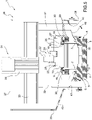
- the reference number 1 indicates, as a whole, a work centre to process section bars 2 made of aluminium, light alloys, PVC or the like having an elongated shape.
- the work centre 1 comprises an elongated base 3, which extends in a horizontal direction 4 and is substantially U-shaped.
- the base 3 is limited by two upper faces 5 inclined towards the centre of the base 3. It is further limited by two parallel and opposite side faces 6 and supports two rows of vertical uprights 7 parallel to each other and to the direction 4.
- each row of uprights 7 extend upwardly from a relative face 5 in a vertical direction 8 transverse to the direction 4 and carry a longitudinal guide member 9 parallel to the direction 4 and connected at their free ends.
- the work centre 1 further has a plurality of support bars 10, which extend between the longitudinal members 9 in a horizontal direction 11 orthogonal to the directions 4 and 8 and are slidably coupled to the longitudinal members 9 to be moved by an actuation device 12 along the base 3 in the direction 4.
- the device 12 comprises, in this case, two belt conveyors 13 parallel to each other (only one of which is shown in Figure 1 ), which extend in the direction 4 and are mounted on opposite sides of the two longitudinal members 9 in the direction 11.
- Each conveyor 13 comprises a belt 14 wound in a ring about a pair of transmission pulleys 15 (only one of which is shown in Figure 1 ) mounted to rotate about respective rotation axes 16 parallel to each other and to the direction 8.
- each conveyor 13 is provided with an actuation motor 17 able to rotate the relative pulleys 15 about the axes 16.
- the device 12 comprises a single actuation motor connected with the pulleys 15 of one of the conveyors 13 and a motion transmission system to the pulleys 15 of the other conveyor 13.
- the belts 14 are removed and replaced with respective chains or ropes.
- Each bar 10 is provided with two hooking devices 18 movable between respective locking positions of the bar 10 to the belts 14 and respective release positions and with two locking devices (not shown) movable between respective locking positions of the bar 10 on the longitudinal members 9 and respective release positions.
- each bar 10 on the longitudinal members 9 is controlled by a torsion shaft (not shown), which is mounted on the bar 10 parallel to the direction 11 and is rotatably coupled to the bar 10 to rotate, with respect to the bar 10, about a rotation axis parallel to the direction 11.
- a torsion shaft (not shown), which is mounted on the bar 10 parallel to the direction 11 and is rotatably coupled to the bar 10 to rotate, with respect to the bar 10, about a rotation axis parallel to the direction 11.
- the torsion shaft (not shown) is provided with two gears 19, which are mounted on the free ends of the torsion shaft (not shown) and are coupled with respective racks 20 fixed to the longitudinal members 9 parallel to the direction 4.
- Each bar 10 is provided with a rectilinear guide 21 fixed on an upper face of the bar 10 parallel to the direction 11 and supports a clamping vise 22 comprising two gripping jaws 23, 24 extending upwards from the bar 10 in the direction 8.
- each vise 22 further comprises a support roller 25, which is mounted to rotate about a rotation axis parallel to the direction 11, and defines, together with the rollers 25 of the other vises 22, a supporting plane P for a section bar 2.
- the roller 25 extends through two slits 26 formed through the relative jaws 23, 24 in the direction 11, is substantially aligned to the relative guide 21 in the direction 8 and is rotatably coupled to the free ends of the output rods 27 of two actuator cylinders 28 formed in the relative bar 10.
- the roller 25 is moved by the cylinders 28 in the direction 8 between a lowered position and a plurality of raised positions based on a height H of the section bar 2 measured parallel to the direction 8.
- each vise 22 is associated with at least one cable-carrying chain 29 housed inside a box-shaped body 30, which has an elongated shape, is fixed to one of the longitudinal members 9 parallel to the direction 4 and is open at the bottom to allow the passage of the chains 29.
- the body 30 is fixed to the uprights 7 parallel to the direction 4.
- the assembly defined by the chain 29 and by the body 30 is arranged at a given distance from the faces 5 of the base 3.
- the chain 29 has a first free end fixed to the body 30 and a second free end fixed to the relative bar 10.
- the chain 29 is configured to guide, during the displacements of the bar 10 along the base 3 in the direction 4, a plurality of electric cables (not shown) and/or of pneumatic and/or hydraulic ducts (not shown) designed to feed the bar 10 and/or the vise 22.
- the work centre 1 further has an overhead crane 31 comprising a pair of vertical uprights 32, which are arranged on opposite sides of the base 3 in the direction 11 and are coupled in a known manner to the side faces 6 of the base 3 to perform linear movements along the base 3 in the direction 4.
- an overhead crane 31 comprising a pair of vertical uprights 32, which are arranged on opposite sides of the base 3 in the direction 11 and are coupled in a known manner to the side faces 6 of the base 3 to perform linear movements along the base 3 in the direction 4.
- the two uprights 32 have, connected at their free ends, a crosspiece 33, which extends above the base 3 in the direction 11 and supports an operating head 34 of known type coupled in a known way to the crosspiece 33 to perform linear movements along the crosspiece 33 in the direction 11.
- the head 34 is configured to perform machining operations, such as milling and/or drilling and/or cutting, of section bars 2.
- the base 3 further supports a belt conveyor 35, which extends between the two longitudinal members 9 beneath the bars 10 and is motorized to remove machining scraps and/or chips produced by the head 34.
- the conveyor 35 is removed and replaced with a central collection tank.
- the overhead crane 31 is associated with a fairing 36, which extends about the overhead crane 31 and is fixed to the overhead crane 31 to move along the base 3 in the direction 4.
- the fairing 36 is limited by two front walls 37 substantially parallel to each other and perpendicular to the direction 4, and is further limited by two side walls 38 substantially parallel to each other and perpendicular to the direction 11.
- Each wall 37 has an opening 39 configured to be slidably engaged by the bars 10 and by the relative vises 22 during the movement of the bars 10 and/or of the overhead crane 31 in the direction 4.
- Each wall 38 is arranged at a distance from the other wall 38 greater than a length of the crosspiece 33 measured parallel to the direction 11.
- the fairing 36 is limited by a bottom wall comprising two discharging chutes 40, which are formed on opposite sides of the base 3 and of the two rows of uprights 7 in the direction 11, and extend between the upper faces 5 of the base 3 and the longitudinal members 9 to convey the machining scraps and/or chips produced by the head 34 first on the faces 5 and then on the conveyor 35.
- Each chute 40 has an inclination substantially equal to the inclination of the relative face 5 and is provided with an opening 41 configured to extend about a relative upright 32 of the overhead crane 31.
- the presence of the uprights 7 and the distance between the longitudinal guide members 9 and the faces 5 of the base 3 allow the chutes 40 to extend below the bars 10, the box-shaped bodies 30 and the cable-carrying chains 29, substantially conveying all of the machining scraps and/or chips produced by the head 34 on the conveyor 35 and keeping substantially clean the space about the bars 10 and the vises 22 and above the faces 5 of the base 3.
Landscapes
- Engineering & Computer Science (AREA)
- Mechanical Engineering (AREA)
- Crystals, And After-Treatments Of Crystals (AREA)
- Forging (AREA)
- Adornments (AREA)
- Electrical Discharge Machining, Electrochemical Machining, And Combined Machining (AREA)
- Feeding Of Workpieces (AREA)
Claims (9)
- Centre d'usinage pour traiter des profilés (2) réalisés à partir d'aluminium, d'alliages légers, de PVC ou similaires comprenant une base allongée (3) qui s'étend dans une première direction (4), est sensiblement en forme de U, supporte un dispositif de collecte central (35) pour expulser les copeaux et/ou déchets d'usinage et est prévue avec deux éléments de guidage longitudinaux (9) parallèles à la première direction (4) ; une pluralité de barres de support (10), dont chacune est montée sur les éléments de guidage longitudinaux (9), s'étend au-dessus du dispositif de collecte (35) dans une seconde direction (11) transversale par rapport à la première direction (4), est mobile le long de la base (3) dans la première direction (4) et supporte au moins une unité de maintien (22) conçue pour maintenir au moins un profilé (2) réalisé à partir d'aluminium, d'alliages légers, de PVC ou similaires ; un pont roulant (31) qui est mobile le long de la base (3) dans la première direction (4) et comprend, à son tour, deux premiers montants verticaux (32) qui sont agencés sur les côtés opposés de la base (3) dans la seconde direction (11), et une traverse horizontale (33) qui s'étend au-dessus de la base (3) dans la seconde direction (11) et est prévue avec une tête opérationnelle (34) pour traiter les profilés (2) ; et un carénage (36) qui s'étend autour du pont roulant (31) et est fixé sur le pont roulant (31) pour se déplacer le long de la base (3) dans la première direction (4) ; et caractérisé en ce qu'il comprend en outre une pluralité de seconds montants verticaux (7) qui sont répartis le long de la base (3), s'étendent vers le haut à partir de la base (3) et sont raccordés au niveau de leurs extrémités libres supérieures avec les deux éléments de guidage longitudinaux (9) ; le carénage (36) ayant deux goulottes de décharge (40), chacune s'étendant entre la base (3) et un élément de guidage longitudinal (9) relatif afin de transporter les copeaux et/ou déchets d'usinage sur le dispositif de collecte (35) ; et chaque barre de support (10) étant associée avec au moins une chaîne porte-câble (29) qui loge, à l'intérieur, au moins un conduit d'alimentation conçu pour alimenter la barre de support (10) et/ou l'unité de maintien (22) relative, est raccordée à la base (3) et à la barre de support (10) afin de guider le conduit d'alimentation pendant le déplacement de la barre de support (10) le long de la base (3) et s'étend à l'intérieur d'au moins un corps de confinement en forme de boîte (30) qui s'étend au-dessus de la base (3) dans la première direction (4) et est fixée aux seconds montants verticaux (7) ou à un élément de guidage longitudinal (9) relatif.
- Centre d'usinage selon la revendication 1, dans lequel la base (3) est limitée par deux faces supérieures (5), chacune desquelles coopérant avec une goulotte de décharge (40) relative et étant inclinée vers le dispositif de collecte (35).
- Centre d'usinage selon la revendication 1 ou 2, dans lequel les deux montants verticaux (7) sont divisés en deux rangées de seconds montants verticaux (7) agencés sur les côtés opposés du dispositif de collecte (35) dans la seconde direction (11).
- Centre d'usinage selon l'une quelconque des revendications précédentes, dans lequel la base (3) est limitée dans la seconde direction (11) par deux faces latérales opposées (6) ; chaque face latérale (6) étant prévue avec un dispositif de guidage mis en prise de manière coulissante par un premier montant vertical (32) relatif.
- Centre d'usinage selon l'une quelconque des revendications précédentes, dans lequel chaque goulotte de décharge (40) a une ouverture (41) conçue pour recevoir un premier montant vertical (32) relatif.
- Centre d'usinage selon l'une quelconque des revendications précédentes, dans lequel le carénage (36) comprend deux parois avant (37) sensiblement parallèles l'une à l'autre et perpendiculaires à la première direction (4), deux parois latérales (38) sensiblement parallèles l'une à l'autre et perpendiculaires à la seconde direction (11) et une paroi inférieure comprenant les deux goulottes de décharge (40).
- Centre d'usinage selon la revendication 6, dans lequel chaque paroi avant (37) a une autre ouverture (39) configurée pour être mise en prise par les barres de support (10) et par les unités de maintien (22) relatives sur la base des mouvements des barres de support (10) et/ou du pont roulant (31) dans la première direction (4) .
- Centre d'usinage selon l'une quelconque des revendications précédentes, dans lequel chaque chaîne porte-câble (29) a une première extrémité libre fixée sur le corps de confinement en forme de boîte et une seconde extrémité libre fixée sur la barre de support (10) relative.
- Centre d'usinage selon l'une quelconque des revendications précédentes, dans lequel chaque conduit d'alimentation est électrique ou pneumatique ou hydraulique.
Applications Claiming Priority (1)
| Application Number | Priority Date | Filing Date | Title |
|---|---|---|---|
| IT102018000009315A IT201800009315A1 (it) | 2018-10-10 | 2018-10-10 | Centro di lavoro per la lavorazione di profilati di alluminio, leghe leggere, pvc o simili |
Publications (2)
| Publication Number | Publication Date |
|---|---|
| EP3636383A1 EP3636383A1 (fr) | 2020-04-15 |
| EP3636383B1 true EP3636383B1 (fr) | 2022-12-14 |
Family
ID=65031639
Family Applications (1)
| Application Number | Title | Priority Date | Filing Date |
|---|---|---|---|
| EP19202588.0A Active EP3636383B1 (fr) | 2018-10-10 | 2019-10-10 | Centre d'usinage pour profiles en aluminium, alliages legers ou pvc. |
Country Status (2)
| Country | Link |
|---|---|
| EP (1) | EP3636383B1 (fr) |
| IT (1) | IT201800009315A1 (fr) |
Families Citing this family (2)
| Publication number | Priority date | Publication date | Assignee | Title |
|---|---|---|---|---|
| CN111570899A (zh) * | 2020-05-08 | 2020-08-25 | 福建革升不锈钢水管有限公司 | 一种铁屑可回收的无缝钢管生产设备及其工艺 |
| CN113334126B (zh) * | 2021-06-26 | 2024-04-16 | 苏州天裕塑胶有限公司 | 一种数控机床上下料系统 |
Family Cites Families (4)
| Publication number | Priority date | Publication date | Assignee | Title |
|---|---|---|---|---|
| DE19732608B4 (de) * | 1997-07-29 | 2004-04-15 | Ex-Cell-O Gmbh | Werkzeugmaschine |
| EP1134055A1 (fr) * | 2000-03-09 | 2001-09-19 | Emmergi S.A., Luxembourg, Lugano Branch | Machine-outil pour usiner des éléments profilés |
| ITBO20130465A1 (it) * | 2013-08-27 | 2015-02-28 | Biesse Spa | Metodo e macchina per la lavorazione di componenti di legno o simili |
| DE202017003923U1 (de) * | 2017-07-26 | 2017-09-18 | Mecal S.R.L. | Bearbeitungszentrum für Metallprofile |
-
2018
- 2018-10-10 IT IT102018000009315A patent/IT201800009315A1/it unknown
-
2019
- 2019-10-10 EP EP19202588.0A patent/EP3636383B1/fr active Active
Also Published As
| Publication number | Publication date |
|---|---|
| EP3636383A1 (fr) | 2020-04-15 |
| IT201800009315A1 (it) | 2020-04-10 |
Similar Documents
| Publication | Publication Date | Title |
|---|---|---|
| EP3950218B1 (fr) | Centre de travail pour traiter des barres de section, en particulier en aluminium, en alliages légers, en pvc ou analogues | |
| EP3254803B1 (fr) | Machine de traitement de barres de section | |
| EP3636386B1 (fr) | Centre d'usinage pour profiles en aluminium, pvc ou alliages legers | |
| EP3636383B1 (fr) | Centre d'usinage pour profiles en aluminium, alliages legers ou pvc. | |
| EP3636384B1 (fr) | Centre d'usinage pour profilés en aluminium, alliages légers ou pvc. | |
| US5827159A (en) | Combination tool changer and storage device for die cutter | |
| CN215247302U (zh) | 一种棒料自动存取设备 | |
| CN114346737B (zh) | 棒材自动送料机 | |
| ITFI20130097A1 (it) | "centro di lavoro" | |
| CN107900539B (zh) | 一种全自动数控激光切管机用输料系统 | |
| KR100623048B1 (ko) | 알루미늄 튜브 자동 인발의 이송트레이장치 | |
| EP3950217B1 (fr) | Procédé de configuration d'un poste de travail pour traiter des barres de section, fabriquées en particulier en aluminium, en alliages légers, en pvc ou analogues | |
| SU1699866A1 (ru) | Механизированный много русный накопитель | |
| KR100647106B1 (ko) | 알루미늄 튜브 다발 자동 인발용 배출트레이장치 | |
| EP3868511B1 (fr) | Centre de travail pour traiter des profilés, en particulier en aluminium, en alliages légers, en pvc ou analogues | |
| EP3868510B1 (fr) | Centre de travail pour traiter des barres de section, en particulier en aluminium, en alliages légers, en pvc ou analogues | |
| CN211444148U (zh) | 一种保温杯3轴取放装置专用机械手 | |
| CN113666107A (zh) | 一种桁架机器人 | |
| CN107352079B (zh) | 一种多支肠用机器人摆肠机 | |
| CN114074128A (zh) | 金属棒材自动拉拔设备 | |
| CN217555129U (zh) | 一种进行物料传输的上下料装置 | |
| CN211418807U (zh) | 一种多工位夹持传送装置 | |
| EP4112223A1 (fr) | Poste de travail pour traiter des barres de section, en particulier en aluminium, en alliages légers, en pvc ou analogues | |
| EP4732977A1 (fr) | Procédé et machine pour couper et/ou usiner des profilés, en particulier en aluminium, en alliages légers, en pvc ou similaire | |
| CN216912559U (zh) | 送管机单根管材抓取装置 |
Legal Events
| Date | Code | Title | Description |
|---|---|---|---|
| PUAI | Public reference made under article 153(3) epc to a published international application that has entered the european phase |
Free format text: ORIGINAL CODE: 0009012 |
|
| STAA | Information on the status of an ep patent application or granted ep patent |
Free format text: STATUS: THE APPLICATION HAS BEEN PUBLISHED |
|
| AK | Designated contracting states |
Kind code of ref document: A1 Designated state(s): AL AT BE BG CH CY CZ DE DK EE ES FI FR GB GR HR HU IE IS IT LI LT LU LV MC MK MT NL NO PL PT RO RS SE SI SK SM TR |
|
| AX | Request for extension of the european patent |
Extension state: BA ME |
|
| STAA | Information on the status of an ep patent application or granted ep patent |
Free format text: STATUS: REQUEST FOR EXAMINATION WAS MADE |
|
| 17P | Request for examination filed |
Effective date: 20201014 |
|
| RBV | Designated contracting states (corrected) |
Designated state(s): AL AT BE BG CH CY CZ DE DK EE ES FI FR GB GR HR HU IE IS IT LI LT LU LV MC MK MT NL NO PL PT RO RS SE SI SK SM TR |
|
| GRAP | Despatch of communication of intention to grant a patent |
Free format text: ORIGINAL CODE: EPIDOSNIGR1 |
|
| STAA | Information on the status of an ep patent application or granted ep patent |
Free format text: STATUS: GRANT OF PATENT IS INTENDED |
|
| RIC1 | Information provided on ipc code assigned before grant |
Ipc: B23Q 11/00 20060101ALI20220609BHEP Ipc: B23Q 7/04 20060101ALI20220609BHEP Ipc: B23Q 1/01 20060101AFI20220609BHEP |
|
| INTG | Intention to grant announced |
Effective date: 20220707 |
|
| GRAS | Grant fee paid |
Free format text: ORIGINAL CODE: EPIDOSNIGR3 |
|
| GRAA | (expected) grant |
Free format text: ORIGINAL CODE: 0009210 |
|
| STAA | Information on the status of an ep patent application or granted ep patent |
Free format text: STATUS: THE PATENT HAS BEEN GRANTED |
|
| AK | Designated contracting states |
Kind code of ref document: B1 Designated state(s): AL AT BE BG CH CY CZ DE DK EE ES FI FR GB GR HR HU IE IS IT LI LT LU LV MC MK MT NL NO PL PT RO RS SE SI SK SM TR |
|
| REG | Reference to a national code |
Ref country code: GB Ref legal event code: FG4D |
|
| REG | Reference to a national code |
Ref country code: CH Ref legal event code: EP |
|
| REG | Reference to a national code |
Ref country code: DE Ref legal event code: R096 Ref document number: 602019023110 Country of ref document: DE |
|
| REG | Reference to a national code |
Ref country code: IE Ref legal event code: FG4D |
|
| REG | Reference to a national code |
Ref country code: AT Ref legal event code: REF Ref document number: 1537388 Country of ref document: AT Kind code of ref document: T Effective date: 20230115 |
|
| REG | Reference to a national code |
Ref country code: LT Ref legal event code: MG9D |
|
| REG | Reference to a national code |
Ref country code: NL Ref legal event code: MP Effective date: 20221214 |
|
| PG25 | Lapsed in a contracting state [announced via postgrant information from national office to epo] |
Ref country code: SE Free format text: LAPSE BECAUSE OF FAILURE TO SUBMIT A TRANSLATION OF THE DESCRIPTION OR TO PAY THE FEE WITHIN THE PRESCRIBED TIME-LIMIT Effective date: 20221214 Ref country code: NO Free format text: LAPSE BECAUSE OF FAILURE TO SUBMIT A TRANSLATION OF THE DESCRIPTION OR TO PAY THE FEE WITHIN THE PRESCRIBED TIME-LIMIT Effective date: 20230314 Ref country code: LT Free format text: LAPSE BECAUSE OF FAILURE TO SUBMIT A TRANSLATION OF THE DESCRIPTION OR TO PAY THE FEE WITHIN THE PRESCRIBED TIME-LIMIT Effective date: 20221214 Ref country code: FI Free format text: LAPSE BECAUSE OF FAILURE TO SUBMIT A TRANSLATION OF THE DESCRIPTION OR TO PAY THE FEE WITHIN THE PRESCRIBED TIME-LIMIT Effective date: 20221214 |
|
| REG | Reference to a national code |
Ref country code: AT Ref legal event code: MK05 Ref document number: 1537388 Country of ref document: AT Kind code of ref document: T Effective date: 20221214 |
|
| PG25 | Lapsed in a contracting state [announced via postgrant information from national office to epo] |
Ref country code: RS Free format text: LAPSE BECAUSE OF FAILURE TO SUBMIT A TRANSLATION OF THE DESCRIPTION OR TO PAY THE FEE WITHIN THE PRESCRIBED TIME-LIMIT Effective date: 20221214 Ref country code: LV Free format text: LAPSE BECAUSE OF FAILURE TO SUBMIT A TRANSLATION OF THE DESCRIPTION OR TO PAY THE FEE WITHIN THE PRESCRIBED TIME-LIMIT Effective date: 20221214 Ref country code: HR Free format text: LAPSE BECAUSE OF FAILURE TO SUBMIT A TRANSLATION OF THE DESCRIPTION OR TO PAY THE FEE WITHIN THE PRESCRIBED TIME-LIMIT Effective date: 20221214 Ref country code: GR Free format text: LAPSE BECAUSE OF FAILURE TO SUBMIT A TRANSLATION OF THE DESCRIPTION OR TO PAY THE FEE WITHIN THE PRESCRIBED TIME-LIMIT Effective date: 20230315 |
|
| PG25 | Lapsed in a contracting state [announced via postgrant information from national office to epo] |
Ref country code: NL Free format text: LAPSE BECAUSE OF FAILURE TO SUBMIT A TRANSLATION OF THE DESCRIPTION OR TO PAY THE FEE WITHIN THE PRESCRIBED TIME-LIMIT Effective date: 20221214 |
|
| PG25 | Lapsed in a contracting state [announced via postgrant information from national office to epo] |
Ref country code: SM Free format text: LAPSE BECAUSE OF FAILURE TO SUBMIT A TRANSLATION OF THE DESCRIPTION OR TO PAY THE FEE WITHIN THE PRESCRIBED TIME-LIMIT Effective date: 20221214 Ref country code: RO Free format text: LAPSE BECAUSE OF FAILURE TO SUBMIT A TRANSLATION OF THE DESCRIPTION OR TO PAY THE FEE WITHIN THE PRESCRIBED TIME-LIMIT Effective date: 20221214 Ref country code: PT Free format text: LAPSE BECAUSE OF FAILURE TO SUBMIT A TRANSLATION OF THE DESCRIPTION OR TO PAY THE FEE WITHIN THE PRESCRIBED TIME-LIMIT Effective date: 20230414 Ref country code: ES Free format text: LAPSE BECAUSE OF FAILURE TO SUBMIT A TRANSLATION OF THE DESCRIPTION OR TO PAY THE FEE WITHIN THE PRESCRIBED TIME-LIMIT Effective date: 20221214 Ref country code: EE Free format text: LAPSE BECAUSE OF FAILURE TO SUBMIT A TRANSLATION OF THE DESCRIPTION OR TO PAY THE FEE WITHIN THE PRESCRIBED TIME-LIMIT Effective date: 20221214 Ref country code: CZ Free format text: LAPSE BECAUSE OF FAILURE TO SUBMIT A TRANSLATION OF THE DESCRIPTION OR TO PAY THE FEE WITHIN THE PRESCRIBED TIME-LIMIT Effective date: 20221214 Ref country code: AT Free format text: LAPSE BECAUSE OF FAILURE TO SUBMIT A TRANSLATION OF THE DESCRIPTION OR TO PAY THE FEE WITHIN THE PRESCRIBED TIME-LIMIT Effective date: 20221214 |
|
| PG25 | Lapsed in a contracting state [announced via postgrant information from national office to epo] |
Ref country code: SK Free format text: LAPSE BECAUSE OF FAILURE TO SUBMIT A TRANSLATION OF THE DESCRIPTION OR TO PAY THE FEE WITHIN THE PRESCRIBED TIME-LIMIT Effective date: 20221214 Ref country code: PL Free format text: LAPSE BECAUSE OF FAILURE TO SUBMIT A TRANSLATION OF THE DESCRIPTION OR TO PAY THE FEE WITHIN THE PRESCRIBED TIME-LIMIT Effective date: 20221214 Ref country code: IS Free format text: LAPSE BECAUSE OF FAILURE TO SUBMIT A TRANSLATION OF THE DESCRIPTION OR TO PAY THE FEE WITHIN THE PRESCRIBED TIME-LIMIT Effective date: 20230414 Ref country code: AL Free format text: LAPSE BECAUSE OF FAILURE TO SUBMIT A TRANSLATION OF THE DESCRIPTION OR TO PAY THE FEE WITHIN THE PRESCRIBED TIME-LIMIT Effective date: 20221214 |
|
| REG | Reference to a national code |
Ref country code: DE Ref legal event code: R097 Ref document number: 602019023110 Country of ref document: DE |
|
| PLBE | No opposition filed within time limit |
Free format text: ORIGINAL CODE: 0009261 |
|
| STAA | Information on the status of an ep patent application or granted ep patent |
Free format text: STATUS: NO OPPOSITION FILED WITHIN TIME LIMIT |
|
| P01 | Opt-out of the competence of the unified patent court (upc) registered |
Effective date: 20230915 |
|
| PG25 | Lapsed in a contracting state [announced via postgrant information from national office to epo] |
Ref country code: DK Free format text: LAPSE BECAUSE OF FAILURE TO SUBMIT A TRANSLATION OF THE DESCRIPTION OR TO PAY THE FEE WITHIN THE PRESCRIBED TIME-LIMIT Effective date: 20221214 |
|
| 26N | No opposition filed |
Effective date: 20230915 |
|
| PG25 | Lapsed in a contracting state [announced via postgrant information from national office to epo] |
Ref country code: SI Free format text: LAPSE BECAUSE OF FAILURE TO SUBMIT A TRANSLATION OF THE DESCRIPTION OR TO PAY THE FEE WITHIN THE PRESCRIBED TIME-LIMIT Effective date: 20221214 |
|
| PG25 | Lapsed in a contracting state [announced via postgrant information from national office to epo] |
Ref country code: IT Free format text: LAPSE BECAUSE OF FAILURE TO SUBMIT A TRANSLATION OF THE DESCRIPTION OR TO PAY THE FEE WITHIN THE PRESCRIBED TIME-LIMIT Effective date: 20221214 Ref country code: MC Free format text: LAPSE BECAUSE OF FAILURE TO SUBMIT A TRANSLATION OF THE DESCRIPTION OR TO PAY THE FEE WITHIN THE PRESCRIBED TIME-LIMIT Effective date: 20221214 |
|
| REG | Reference to a national code |
Ref country code: CH Ref legal event code: PL |
|
| REG | Reference to a national code |
Ref country code: BE Ref legal event code: MM Effective date: 20231031 |
|
| PG25 | Lapsed in a contracting state [announced via postgrant information from national office to epo] |
Ref country code: LU Free format text: LAPSE BECAUSE OF NON-PAYMENT OF DUE FEES Effective date: 20231010 |
|
| GBPC | Gb: european patent ceased through non-payment of renewal fee |
Effective date: 20231010 |
|
| PG25 | Lapsed in a contracting state [announced via postgrant information from national office to epo] |
Ref country code: LU Free format text: LAPSE BECAUSE OF NON-PAYMENT OF DUE FEES Effective date: 20231010 |
|
| PG25 | Lapsed in a contracting state [announced via postgrant information from national office to epo] |
Ref country code: GB Free format text: LAPSE BECAUSE OF NON-PAYMENT OF DUE FEES Effective date: 20231010 |
|
| PG25 | Lapsed in a contracting state [announced via postgrant information from national office to epo] |
Ref country code: CH Free format text: LAPSE BECAUSE OF NON-PAYMENT OF DUE FEES Effective date: 20231031 |
|
| PG25 | Lapsed in a contracting state [announced via postgrant information from national office to epo] |
Ref country code: GB Free format text: LAPSE BECAUSE OF NON-PAYMENT OF DUE FEES Effective date: 20231010 Ref country code: CH Free format text: LAPSE BECAUSE OF NON-PAYMENT OF DUE FEES Effective date: 20231031 |
|
| PG25 | Lapsed in a contracting state [announced via postgrant information from national office to epo] |
Ref country code: BE Free format text: LAPSE BECAUSE OF NON-PAYMENT OF DUE FEES Effective date: 20231031 |
|
| PG25 | Lapsed in a contracting state [announced via postgrant information from national office to epo] |
Ref country code: IE Free format text: LAPSE BECAUSE OF NON-PAYMENT OF DUE FEES Effective date: 20231010 |
|
| PG25 | Lapsed in a contracting state [announced via postgrant information from national office to epo] |
Ref country code: IE Free format text: LAPSE BECAUSE OF NON-PAYMENT OF DUE FEES Effective date: 20231010 |
|
| PG25 | Lapsed in a contracting state [announced via postgrant information from national office to epo] |
Ref country code: BG Free format text: LAPSE BECAUSE OF FAILURE TO SUBMIT A TRANSLATION OF THE DESCRIPTION OR TO PAY THE FEE WITHIN THE PRESCRIBED TIME-LIMIT Effective date: 20221214 |
|
| PG25 | Lapsed in a contracting state [announced via postgrant information from national office to epo] |
Ref country code: BG Free format text: LAPSE BECAUSE OF FAILURE TO SUBMIT A TRANSLATION OF THE DESCRIPTION OR TO PAY THE FEE WITHIN THE PRESCRIBED TIME-LIMIT Effective date: 20221214 |
|
| PG25 | Lapsed in a contracting state [announced via postgrant information from national office to epo] |
Ref country code: CY Free format text: LAPSE BECAUSE OF FAILURE TO SUBMIT A TRANSLATION OF THE DESCRIPTION OR TO PAY THE FEE WITHIN THE PRESCRIBED TIME-LIMIT; INVALID AB INITIO Effective date: 20191010 |
|
| PG25 | Lapsed in a contracting state [announced via postgrant information from national office to epo] |
Ref country code: HU Free format text: LAPSE BECAUSE OF FAILURE TO SUBMIT A TRANSLATION OF THE DESCRIPTION OR TO PAY THE FEE WITHIN THE PRESCRIBED TIME-LIMIT; INVALID AB INITIO Effective date: 20191010 |
|
| PGFP | Annual fee paid to national office [announced via postgrant information from national office to epo] |
Ref country code: TR Payment date: 20250919 Year of fee payment: 7 |
|
| PGFP | Annual fee paid to national office [announced via postgrant information from national office to epo] |
Ref country code: DE Payment date: 20251028 Year of fee payment: 7 |
|
| PGFP | Annual fee paid to national office [announced via postgrant information from national office to epo] |
Ref country code: FR Payment date: 20251027 Year of fee payment: 7 |