EP3638324B1 - Procédé pour la fabrication d'un plateau perforé de stérilisation pourvu d'un fond structuré à trois dimensions - Google Patents
Procédé pour la fabrication d'un plateau perforé de stérilisation pourvu d'un fond structuré à trois dimensions Download PDFInfo
- Publication number
- EP3638324B1 EP3638324B1 EP19708838.8A EP19708838A EP3638324B1 EP 3638324 B1 EP3638324 B1 EP 3638324B1 EP 19708838 A EP19708838 A EP 19708838A EP 3638324 B1 EP3638324 B1 EP 3638324B1
- Authority
- EP
- European Patent Office
- Prior art keywords
- processing step
- sieve basket
- basket
- base
- inner portion
- Prior art date
- Legal status (The legal status is an assumption and is not a legal conclusion. Google has not performed a legal analysis and makes no representation as to the accuracy of the status listed.)
- Active
Links
Images


Classifications
-
- A—HUMAN NECESSITIES
- A61—MEDICAL OR VETERINARY SCIENCE; HYGIENE
- A61B—DIAGNOSIS; SURGERY; IDENTIFICATION
- A61B50/00—Containers, covers, furniture or holders specially adapted for surgical or diagnostic appliances or instruments, e.g. sterile covers
- A61B50/30—Containers specially adapted for packaging, protecting, dispensing, collecting or disposing of surgical or diagnostic appliances or instruments
-
- A—HUMAN NECESSITIES
- A61—MEDICAL OR VETERINARY SCIENCE; HYGIENE
- A61L—METHODS OR APPARATUS FOR STERILISING MATERIALS OR OBJECTS IN GENERAL; DISINFECTION, STERILISATION OR DEODORISATION OF AIR; CHEMICAL ASPECTS OF BANDAGES, DRESSINGS, ABSORBENT PADS OR SURGICAL ARTICLES; MATERIALS FOR BANDAGES, DRESSINGS, ABSORBENT PADS OR SURGICAL ARTICLES
- A61L2/00—Disinfection or sterilisation of materials or objects, in general; Accessories therefor
- A61L2/26—Accessories
-
- A—HUMAN NECESSITIES
- A61—MEDICAL OR VETERINARY SCIENCE; HYGIENE
- A61B—DIAGNOSIS; SURGERY; IDENTIFICATION
- A61B50/00—Containers, covers, furniture or holders specially adapted for surgical or diagnostic appliances or instruments, e.g. sterile covers
- A61B50/20—Holders specially adapted for surgical or diagnostic appliances or instruments
-
- A—HUMAN NECESSITIES
- A61—MEDICAL OR VETERINARY SCIENCE; HYGIENE
- A61B—DIAGNOSIS; SURGERY; IDENTIFICATION
- A61B50/00—Containers, covers, furniture or holders specially adapted for surgical or diagnostic appliances or instruments, e.g. sterile covers
- A61B50/30—Containers specially adapted for packaging, protecting, dispensing, collecting or disposing of surgical or diagnostic appliances or instruments
- A61B50/34—Baskets
-
- A—HUMAN NECESSITIES
- A61—MEDICAL OR VETERINARY SCIENCE; HYGIENE
- A61B—DIAGNOSIS; SURGERY; IDENTIFICATION
- A61B50/00—Containers, covers, furniture or holders specially adapted for surgical or diagnostic appliances or instruments, e.g. sterile covers
- A61B50/20—Holders specially adapted for surgical or diagnostic appliances or instruments
- A61B50/22—Racks
-
- A—HUMAN NECESSITIES
- A61—MEDICAL OR VETERINARY SCIENCE; HYGIENE
- A61L—METHODS OR APPARATUS FOR STERILISING MATERIALS OR OBJECTS IN GENERAL; DISINFECTION, STERILISATION OR DEODORISATION OF AIR; CHEMICAL ASPECTS OF BANDAGES, DRESSINGS, ABSORBENT PADS OR SURGICAL ARTICLES; MATERIALS FOR BANDAGES, DRESSINGS, ABSORBENT PADS OR SURGICAL ARTICLES
- A61L2103/00—Materials or objects being the target of disinfection or sterilisation
- A61L2103/15—Laboratory, medical or dentistry appliances, e.g. catheters or sharps
-
- A—HUMAN NECESSITIES
- A61—MEDICAL OR VETERINARY SCIENCE; HYGIENE
- A61L—METHODS OR APPARATUS FOR STERILISING MATERIALS OR OBJECTS IN GENERAL; DISINFECTION, STERILISATION OR DEODORISATION OF AIR; CHEMICAL ASPECTS OF BANDAGES, DRESSINGS, ABSORBENT PADS OR SURGICAL ARTICLES; MATERIALS FOR BANDAGES, DRESSINGS, ABSORBENT PADS OR SURGICAL ARTICLES
- A61L2202/00—Aspects relating to methods or apparatus for disinfecting or sterilising materials or objects
- A61L2202/10—Apparatus features
- A61L2202/17—Combination with washing or cleaning means
Definitions
- the present invention relates to a method for producing a sterilization sieve tray, also called a sieve basket, such as a sterilization or disinfection sieve basket, for receiving medical objects to be disinfected or sterilized according to the preamble of claim 1.
- Generic sieve baskets are used to provide a portable receptacle for a number of objects to be disinfected or sterilized, such as surgical gripping instruments, in a washer-disinfector (WD) or autoclave in a reprocessing unit for medical devices (RUMD).
- WD washer-disinfector
- RUMD reprocessing unit for medical devices
- the primary purpose of a sieve basket is to hold multiple items within its interior so that they can be handled as a single unit during the cleaning process. To ensure a compact loading of the sieve basket, it is important to prevent the items from shifting or slipping during the packing process.
- a strainer basket should have as few or no sections as possible in which cleaning fluid (i.e. water with additives) used during the cleaning process collects, so that the cleaning fluid used drains/drips out of the strainer basket as completely as possible after the cleaning process.
- cleaning fluid i.e. water with additives
- a sieve basket which is adapted to hold objects to be disinfected or sterilized.
- the sieve basket has a base, in particular a sheet metal base, which is provided with a plurality of perforations.
- the base has a base plane delimited by side walls, which is produced in a single forming step.
- This base plate is designed as a flat, perforated sheet. To prevent the objects being held from shifting or slipping, a mat is inserted into the basket. This mat prevents the basket from draining efficiently, so that residual water, even after the basket has been removed from the washer-disinfector, causes annoying moistening of various areas of the basket, especially the basket base.
- the problem of disturbing moisture buildup on the bottom of the screen basket persists even if the mat is not inserted.
- the flat base ensures that a surface contact is formed between the objects picked up by the screen basket and the floor, corresponding to the remaining web widths between the plate holes. Residual water collects there under capillary action, which in turn promotes disturbing moisture buildup.
- Wire mesh has a ribbed base that prevents the objects it contains from slipping or sliding. Furthermore, wire mesh creates less surface contact, for example, with a flat surface, and thus reduces capillary action.
- wire mesh basket strainers are disadvantages that not only residual water but also dirt accumulates in the individual nodes of the mesh. Furthermore, after a certain period of use, a breakage or detachment of the individual wires, which significantly increases the risk of injury posed by a sieve basket wire mesh.
- the wall perforation corresponds to the base perforation. Therefore, even if the wire mesh is sufficiently coarsely woven to prevent the objects it holds from shifting or slipping on the base, it has the disadvantage that the wall perforation is so coarse that the objects it holds can protrude through it, which again increases the risk of injury and complicates handling.
- a wire mesh screen basket is also more complex to manufacture, as it does not use inexpensive sheet metal as the starting material.
- Sieve baskets are also known from the DE 101 24 253 A1 and the DE 10 2010 050919 A1 .
- state-of-the-art basket strainers and their manufacturing processes all have the disadvantage that they continue to moisten other surfaces, even after removal from the washer-disinfector, due to residual water.
- they also have the disadvantage of an increased risk of injury, the disadvantage of objects slipping or slipping, and/or the disadvantage of contamination or the accumulation of germs.
- their manufacturing processes are generally not very sophisticated.
- the present invention is based on the object of eliminating or at least mitigating the disadvantages of the prior art and, in particular, of disclosing an efficient manufacturing process which economically enables the mass production of strainer baskets which drain quickly, are compact to load and pose a low risk of injury.
- spacer feet/nubs for example, on the outside/underside of a flat perforated plate processed into a sieve basket base, could potentially reduce the contact area between the sieve basket and a flat surface and thus improve the overall drainage behavior.
- the production of such a special plate would be complex and expensive and therefore uneconomical.
- the spacer feet/nubs would be distributed at a specific distance from one another across the plate surface, which could potentially bend depending on the choice of the distance between two adjacent spacer feet/nubs. For these reasons, such a solution to the problem posed at the beginning has proven to be ineffective.
- the basic idea of the present invention now pursues the basic concept of simulating the spatial structure of a wire mesh in an initially flat perforated plate by deforming the webs extending (and intersecting) between the plate holes (pores) at least partially or in sections in one or more directions different from their respective web extension direction, whereby the deformed webs themselves at least partially define point-like contact areas, for example with a flat substrate.
- This allows virtually any initially flat perforated plate to be designed/retrofitted with this additional capability, namely the provision of an almost arbitrarily selectable number of point-like contact areas in the form of correspondingly three-dimensionally extending plate webs between the plate holes, for example by subjecting the initially flat perforated plate to a corresponding (final) deformation step.
- perforated plate in this application refers to a plate extending in two main spatial directions, preferably made of sheet material with the constant thickness / material thickness of the sheet in a third secondary direction understood.
- the perforated plate additionally receives a three-dimensional, varying structure which deviates from the flat plate with the constant plate thickness/plate thickness. It is advantageous not to form the indentations/bulges in the macro range, i.e. to form a single indentation/bulge across a plurality/multiplicity of webs, but to provide the indentations/bulges in the micro range, i.e.
- the respective indentation/bulge for example, essentially within/along a respective web (preferably between two or three crossing points/nodes with the respective other webs) and/or at a respective selected node point (area within a number of circular nodes immediately surrounding a single node point as the center and thus contact point).
- At least the bottom of the screen basket has or consists of a perforated plate, preferably as a sheet metal part, which, preferably periodically, three-dimensional corrugations or indentations, also indentations/bulges or dents, which protrude from a base plane formed by the initially flat perforated plate towards the inside/inwards of the screen basket and/or towards the outside/outwards of the screen basket, so that the perforated plate or sheet metal base has/receives a surface similar to a (wire) mesh.
- a mesh surface structure is imitated/simulated/reproduced or reproduced by a perforated plate/sheet metal part, whereby the structure of a mesh and that of a perforated sheet are synergistically combined.
- at least the sheet metal part or the perforated plate of at least the screen basket base has/receives a number of through holes (pores) which are circumferentially delimited by overlapping/crossing webs and spaced from one another according to the web width.
- deformations are formed in/on individual webs in one or more directions different from their respective web extension direction, in particular (alternately) in the direction of the outside and/or inside of the screen basket, whereby a rough/toothed contact surface is created on the outside of the base and/or a rough/toothed support surface on the inside of the base.
- a basic form of a screen basket can be produced in just a few steps using a sheet metal that is inexpensive to obtain and easy to process by cutting, punching and bending.
- This basic form of screen basket (after welding the side walls together) would theoretically already be suitable for use in a WD.
- a fifth processing step preferably a forming step, particularly preferably an embossing step, is provided after the third processing step, but not necessarily after the fourth processing step, which results in at least partially a three-dimensionally structured base with the structure described above from at least the flat inner section (which defines the screen basket base).
- the previously flat base of the The screen basket is provided with a ribbed structure without causing any deformation in other areas of the screen basket not intended for embossing during the fifth processing step / embossing.
- the invention can be functionally described as a screen basket with a bottom made of a perforated plate, preferably made of sheet metal, which bottom has the surface geometry and structure of a mesh, but without being braided.
- the invention achieves the advantages of a mesh (bottom structure with contact and fixation surfaces, efficient draining) without its disadvantages (see below).
- Braiding entails that two braided strands/wires overlap/lie on top of each other at the nodes.
- Such overlapping is associated with the significant disadvantage for screen baskets that germs and dirt particles accumulate in the overlapping area, i.e., the node, since these are difficult to reach and thus difficult to clean.
- a mesh is significantly more complex to manufacture than sheet metal processing.
- the inventive "mesh simulation" efficiently eliminates the disadvantages of the prior art.
- the inventive idea lies in the fact that by producing a mesh-like / mesh-simulating base plate, on the one hand, slipping of the objects to be cleaned during the packing process of the sieve basket is prevented, while on the other hand the presence of residual water in the sieve basket after the cleaning process in the RDG is reduced or even avoided, so that there is no disturbing humidification (for example of the packing table).
- the fifth processing step/embossing takes place before the fourth processing step.
- the embossing of the three-dimensional structure takes place immediately after the smoothing of the already cut and punched inner and outer areas. This takes place on the base plate/workpiece, meaning that the partially machined base plate/workpiece still has a low height during the stamping process (because no side walls are yet bent), so that an inserted stamping tool requires only a small amount of vertical movement. Furthermore, in this case, it would also be possible to stamp the outer areas of the base plate intended as side walls accordingly.
- the processing steps from the first processing step to the fifth processing step can be performed chronologically in exactly this order.
- the cut and already punched sheet metal part is bent into a screen basket with side walls extending vertically from the base, before the base is stamped (fifth step) to create the three-dimensional structure as defined above.
- This procedure then has the advantage that prior art manufacturing processes can be converted so that the fifth processing step according to the invention can be carried out following the previous process, or existing screen baskets made of perforated sheet metal can be subsequently provided with a corresponding three-dimensional structure.
- a sixth processing step preferably a (for example, material-to-material) joining step, particularly preferably a welding step such as fusion welding, takes place after the fourth processing step.
- This step firmly connects the individual edge sections, which now represent the side walls of the screen basket, to one another at the edges.
- the fifth processing step can be performed either before or after the sixth processing step.
- the sixth processing step guarantees a robust construction of the screen basket.
- a further advantageous embodiment is characterized in that the openings/holes obtained in the second processing step/punching produce perforations with different structures in the flat inner section and the outer or edge section.
- the punching tool has differently designed or selectable active surfaces distributed across the base area for such structuring.
- At least one stamp similar to an embossing stamp, is used.
- This stamp is pressed by a press onto at least part of the flat inner section (hereinafter the screen basket base) of the already cut and perforated base plate in such a way that the part of the inner section conforms plastically to the negative mold of the stamp. This allows the desired three-dimensional structure to be manufactured with high precision.
- a plurality of stamps is used in this stamping step, so that the entire flat inner section is designed as a three-dimensionally structured base. Further preferably, the corresponding stamps have the same structure, so that the flat inner section is uniformly deformed. Because the entire inner section in this embodiment is designed as a three-dimensionally structured base, the (introduced) draining of the strainer basket occurs quickly, resulting in the associated advantages.
- the punch has a shape/configuration such that the three-dimensionally structured base produced in the fifth processing step has (periodic) corrugations or indentations that protrude toward the interior and/or exterior of the screen basket, so that the base has a mesh-like surface.
- This mesh simulation synergistically combines the advantages of sheet metal screen baskets with wire screen baskets.
- a further advantageous embodiment is characterized in that the stamp is designed such that the three-dimensionally structured base produced in the fifth processing step is constructed from a plurality of longitudinal strut pairs/longitudinal web pairs and transverse strut pairs/transverse web pairs, each running parallel in the base plane and perpendicular to each other in a plan view of the structured base.
- the fifth processing step deforms the base exclusively in the vertical direction of the screen basket, i.e., toward the interior and/or exterior of the screen basket, while maintaining a lattice structure advantageous for packing in the plan view.
- the stamp used in the method according to the invention is further preferably designed such that the three-dimensionally structured base forms contact and fixing surfaces for objects to be placed in the sieve basket. This increases the positional stability of the received objects, and no (silicone) mat is required to ensure secure, positive adhesion of the individual objects.
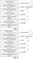
- Fig. 1 shows a first possibility of a process sequence for producing a sieve basket 1 (cf. Fig. 7 ) chronologically.
- Laser cutting I, punching II (also punching and nibbling, provided the part to be punched out is only partially punched and partially broken), rolling III, stamping V, bending IV, and welding VI are carried out in chronological order.
- Fig. 2 shows a second possible process sequence chronologically. This involves laser cutting I, punching II (also punching and nibbling, provided the part to be punched is only partially punched and partially broken), rolling III, bending IV, stamping V, and welding VI, all performed chronologically one after the other.
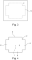
- FIG. 3 A rectangular sheet metal blank 2 is shown. This can have any shape. Its material thickness is approximately 0.5 mm to 2 mm, preferably approximately 1.5 mm. Fig. 3 already indicates a cutting contour 12 along which the laser cutting I is carried out.
- Fig. 4 shows a screen basket base surface 3 that was cut out of the sheet metal blank 2 along the cutting contour 12.
- the screen basket base surface 3 already has areas 7' and 8', which are modified after further processing into a flat inner section 7 and edge sections 8, respectively (cf. Fig. 5 ).
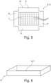
- a perforated starting form 5 is produced, cf. Fig. 5 , which has punched openings 4 as shown in Fig. 5 are indicated schematically.
- the sheet metal exhibits certain residual stresses after cutting I and punching II, which lead to a deformation of the initial shape 5. Consequently, rolling III must now be carried out, which flattens/smoothes the sheet metal in order to obtain a perforated plane 6.
- the initial shape 5 cannot be distinguished from the perforated plane 6, which is why in Fig. 5 both reference symbols were used.
- Fig. 5 the inner section 7 and the edge sections 8. These are preferably punched with different tools so that they have different perforations.
- the subject of the embossing V according to the invention which produces the desired three-dimensional structure in the manner of a braided imitation, is exclusively the inner section 7 or the inner section 7 and the edge sections 8.
- a raw base 10 corresponds to the inner section 7.
- the (flat) raw base 10 has the corrugations according to the invention (cf. Figs. 9, 10 ) on.
- Fig. 7 shows a strainer basket 1 for holding objects to be cleaned, with a plurality of openings 4, as also shown in the detailed view in Fig. 8 can be seen.
- the floor 11 has, as shown in the detailed view Fig. 9 recognizable, periodic corrugations or dents 14. These corrugations 14 protrude from the base plane to the screen basket interior 15 and, in this case, also to the screen basket exterior 16, so that the sheet metal part/base 11 takes on the mesh structure surface.
- Fig. 8 which represents a plan view of a section of the floor 11, the floor 11 has a lattice structure in projection.
- This structure is composed of a plurality of longitudinal strut pairs 17 (also called longitudinal web pairs) and transverse strut pairs 18 (also called transverse web pairs) running parallel in the ground plane, ie in the present plan view.
- a single pair of longitudinal struts 17 consists of two longitudinal struts 19, 20. These longitudinal struts 19, 20 run parallel to each other in the base plane, ie, in the present plan view. When viewed in three dimensions (cf. Figs. 9 and 10 ) it can be seen that each strut 19, 20 has a different, approximately complementary geometry in the third spatial direction, namely towards the screen basket interior 15 and/or the screen basket exterior 16.
- a single pair of cross braces 18 consists of two cross braces 21, 22. These cross braces 21, 22 run parallel to each other in the base plane, ie, in the present plan view. When viewed in three dimensions (cf. Figs. 9 and 10 ) it can be seen that each strut 21, 22 has a different, approximately complementary geometry in the third spatial direction, namely towards the screen basket interior 15 and/or the screen basket exterior 16.
- the surface spanned by the openings 4 fulfills two functions. Firstly, it provides a contact and fixing surface 23 on the edge surface of each strut 19 to 22 facing the opening 4. This surface 23 increases with the size of the openings 4. The larger the objects to be inserted, the larger the openings 4 must be designed so that sufficient contact and fixing surface 23 is available. Secondly, the surface spanned by the openings 4 allows the cleaning fluid to drip out of the sieve basket 1. The drip function also increases with the size of the Openings 4. Accordingly, the second function also encourages keeping the area ratio between the pairs of struts 17, 18 and the area spanned by the openings 4 less than 1. The maximum area spanned by the openings 4 is set in that it must be small enough to prevent equipment to be cleaned from falling out.
- the lattice structure defined by the base 11 has the base nodes 24 resulting from the embossing V. According to the invention, these base nodes 24 do not lie in the same plane, since the corrugations 14 are formed.
- a particular advantage of the invention is that the base nodes 24, each formed by intersecting a longitudinal strut 19, 20 with a transverse strut 21, 22, have almost the same material thickness as the respective longitudinal or transverse strut 19 to 22.
- the mesh simulation according to the invention not only enables an imitation of a mesh, but also has the advantage over a mesh that in the area of the node 24 there is no overlap, i.e. doubling of the material thickness, but the same constant material thickness as in the rest of the floor.
- the floor nodes 24 can be hypothetically connected to one another in order to identify the first hypothetical connecting line 25.
- the floor nodes 24 connected by the first hypothetical connecting line 25 represent floor nodes 24 which, according to an advantageous embodiment of the invention, are each arranged at the same height and protrude into the screen basket interior 15. They each represent, so to speak, a wave crest 27 (see Fig. 9 ) of the periodic undulations 14.
- a second hypothetical connecting line 26 can be seen next to the line 25. This results from connecting the ground nodes 24 omitted from the first hypothetical connecting line 25.
- the ground nodes 24 connected by the second hypothetical connecting line 26 represent such Bottom nodes 24, which according to an advantageous embodiment of the invention are each arranged at the same height and protrude towards the screen basket exterior 16. They each represent a wave trough 28 (see Fig. 9 ) of the periodic undulations 14.
- Fig. 9 represents a sectional drawing through the floor 11 (cf. area ix of Fig. 7 ).
- the strut shown here represents a longitudinal strut 19, 20, which, however, does not differ structurally in its basic form from a transverse strut 21, 22.
- the visible edges show that a first transverse strut 21 extends from each wave crest 27 of the longitudinal strut 19, 20, while a second transverse strut 22 extends from each wave trough 28.
- the reciprocity of the wave crests 27 and wave troughs 28 described above can be clearly seen here.
- the longitudinal strut 19, 20 has a square shape.
- this shape is only exemplary. In other embodiments, an approximately sinusoidal waveform is particularly desired.
- Fig. 9 shows furthermore that the material thickness of the floor node 24 does not exceed that of the remaining longitudinal struts 19, 20, which means that despite the mesh simulation there is no disadvantageous overlap of the struts, as described at the beginning.
- the corrugations 14 are shown in perspective.
- the first hypothetical connecting line 25 (cf. Fig. 8 ) connects the wave crests 27,
- the second hypothetical connecting line 26 (cf. Fig. 8 ) connects the wave troughs 28.
- the three-dimensional roof shape formed between four adjacent floor nodes 24 is composed of two triangles. The vertex of these triangles can be placed, depending on the perspective, between the two wave crests 27 of the four adjacent floor nodes 24 (in which case the roof is closed towards the interior 15 of the screen basket) or between the two wave troughs 28 of the four adjacent floor nodes 24 (in which case the roof is open towards the interior 15 of the screen basket and closed towards the exterior 16 of the screen basket).
- Fig. 10 shows that the structure formed by the V-shaped embossing, which in the projected top view consists of Fig. 8 Showing a rectangular grid structure, it has a high degree of spatiality when viewed from perspective, which reduces the wetting of that surface by drops after removal from the washer-disinfector. Furthermore, the structure created by the corrugations 14 provides sufficiently large contact and fixation surfaces 23.
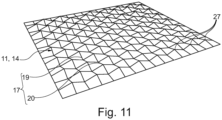
- Fig. 11 shows the three-dimensional corrugations 14 and the resulting ribbing in a further section. So many corrugations 14 are arranged over the entire surface of the base 11 that the totality of the corrugation crests 27 and corrugation troughs 28 gives the user the impression of an almost flat surface.
- the advantages of a flat surface (such as the easy placement of the screen basket) are realized while avoiding its disadvantages (see above).
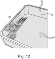
- Fig. 12 depicts a section of a sieve basket 1.
- the sieve basket 1 has, in addition to the base 11, the side walls 13. These also have openings 30, which, however, differ geometrically from those in the base 11. In the present case, the openings 30 are finer-meshed than the openings 4, so that in such a case, in which the objects 29 slide towards the side wall 13, there is no risk of pointed sections of the objects 29 protruding laterally.
- the side walls 13 are also smooth, i.e. explicitly not corrugated.
Landscapes
- Health & Medical Sciences (AREA)
- Life Sciences & Earth Sciences (AREA)
- Surgery (AREA)
- Animal Behavior & Ethology (AREA)
- Veterinary Medicine (AREA)
- Public Health (AREA)
- General Health & Medical Sciences (AREA)
- Engineering & Computer Science (AREA)
- Molecular Biology (AREA)
- Medical Informatics (AREA)
- Heart & Thoracic Surgery (AREA)
- Biomedical Technology (AREA)
- Nuclear Medicine, Radiotherapy & Molecular Imaging (AREA)
- Epidemiology (AREA)
- Filtering Materials (AREA)
- Rigid Containers With Two Or More Constituent Elements (AREA)
Claims (10)
- Procédé de fabrication d'un panier à tamis (1) pour la réception d'objets médicaux à désinfecter ou à stériliser, pour lequel à partir d'une ébauche en plaque, de préférence en tôle (2),- une plaque de base comprenant le fond et les parois latérales du panier à tamis d'un seul tenant ou surface de base de panier à tamis (3) est fabriquée dans une première étape d'usinage (1), de préférence une séparation, le plus préférentiellement une découpe, telle qu'une découpe au laser,- l'ébauche en plaque, en particulier en tôle (2) ou la surface de base de panier à tamis (3) est pourvue d'interruptions ou de trous (4) dans une deuxième étape d'usinage (II) se déroulant temporellement avant ou après la première étape d'usinage (I), de préférence une séparation, le plus préférentiellement un estampage afin d'obtenir une forme de départ (5) perforée,- un plan (6) perforé ou troué est fabriqué dans une troisième étape d'usinage (III) se déroulant temporellement après la première et la deuxième étape d'usinage (I, II), de préférence un façonnage, le plus préférentiellement un laminage ou aplatissement, plan qui est divisé en une section intérieure (7) plane représentant le fond et les sections de bord (8) représentant les parois latérales,- une forme de panier à tamis (9) avec un fond brut et des parois latérales s'étendant verticalement à celui-ci est fabriquée dans une quatrième étape d'usinage (IV) se déroulant temporellement après la troisième étape d'usinage (III), de préférence un façonnage, le plus préférentiellement un pliage, dont le fond brut (10) correspond à la section intérieure (7) plane et les parois latérales correspondent aux sections de bord (8) planes du plan perforé (6),caractérisé par
une cinquième étape d'usinage (V) se déroulant temporellement directement ou indirectement après la troisième étape d'usinage (III), de préférence un façonnage, le plus préférentiellement un gaufrage qui fabrique au moins en partie au moins à partir de la section intérieure (7) plane un fond (11) structuré en trois dimensions. - Procédé selon la revendication 1, caractérisé en ce que la cinquième étape d'usinage (V) se déroule temporellement avant la quatrième étape d'usinage (IV).
- Procédé selon la revendication 1, caractérisé en ce que les étapes d'usinage de la première étape d'usinage (I) à la cinquième étape d'usinage (V) se déroulent temporellement chronologiquement dans cet ordre.
- Procédé selon l'une quelconque des revendications précédentes, caractérisé en ce qu' une sixième étape d'usinage, de préférence un assemblage, le plus préférentiellement un soudage, tel qu'un soudage par liaison de fusion se déroule temporellement après la quatrième étape d'usinage, qui relie entre elles les sections de bord (8) individuelles qui représentent désormais des parois latérales (13) du panier à tamis (1).
- Procédé selon l'une quelconque des revendications précédentes, caractérisé en ce que les interruptions (4) obtenues dans la deuxième étape d'usinage (II) provoquent des perforations structurées différemment l'une à l'autre dans la section intérieure (7) plane et la section de bord (8).
- Procédé selon l'une quelconque des revendications précédentes, caractérisé en ce que lors de la cinquième étape d'usinage (V) au moins un poinçon est utilisé, lequel est pressé par une presse sur une partie de la section intérieure (7) plane de telle manière que la partie de la section intérieure (7) s'adapte plastiquement à la forme négative du poinçon.
- Procédé selon la revendication 6, caractérisé en ce qu' une pluralité de poinçons est utilisée de sorte que la section intérieure (7) plane entière soit configurée comme fond (12) structuré en trois dimensions.
- Procédé selon l'une quelconque des revendications 6 ou 7, caractérisé en ce que le poinçon est tel que le fond (11) structuré en trois dimensions fabriqué dans la cinquième étape d'usinage (V) présente des ondulations ou des bosses (14) qui font saillie vers l'intérieur du panier à tamis (15) et/ou l'extérieur de panier à tamis (16) de sorte que le fond (11) présente une surface comme un treillis.
- Procédé selon l'une quelconque des revendications 6 à 8, caractérisé en ce que le poinçon est tel que le fond (11) structuré en trois dimensions fabriqué dans la cinquième étape d'usinage (V) est constitué d'une pluralité de paires d'entretoises longitudinales (17) et de paires d'entretoises transversales (18) s'étendant respectivement parallèlement dans le plan de base qui s'étendent dans une vue en élévation du fond structuré (11) perpendiculairement les unes aux autres.
- Procédé selon l'une quelconque des revendications 6 à 9, caractérisé en ce que le poinçon est tel que le fond (11) structuré en trois dimensions forme des surfaces d'installation et de fixation (23) pour des objets (30) à placer dans le panier à tamis (1).
Applications Claiming Priority (2)
| Application Number | Priority Date | Filing Date | Title |
|---|---|---|---|
| DE102018104939.0A DE102018104939A1 (de) | 2018-03-05 | 2018-03-05 | Verfahren zum Herstellen einer Sterilisiersiebschale mit einem dreidimensional strukturierten Boden |
| PCT/EP2019/055183 WO2019170551A1 (fr) | 2018-03-05 | 2019-03-01 | Procédé pour la fabrication d'un plateau perforé de stérilisation pourvu d'un fond structuré à trois dimensions |
Publications (2)
| Publication Number | Publication Date |
|---|---|
| EP3638324A1 EP3638324A1 (fr) | 2020-04-22 |
| EP3638324B1 true EP3638324B1 (fr) | 2025-04-30 |
Family
ID=65657470
Family Applications (1)
| Application Number | Title | Priority Date | Filing Date |
|---|---|---|---|
| EP19708838.8A Active EP3638324B1 (fr) | 2018-03-05 | 2019-03-01 | Procédé pour la fabrication d'un plateau perforé de stérilisation pourvu d'un fond structuré à trois dimensions |
Country Status (5)
| Country | Link |
|---|---|
| US (1) | US11931476B2 (fr) |
| EP (1) | EP3638324B1 (fr) |
| CN (1) | CN111787957A (fr) |
| DE (1) | DE102018104939A1 (fr) |
| WO (1) | WO2019170551A1 (fr) |
Families Citing this family (3)
| Publication number | Priority date | Publication date | Assignee | Title |
|---|---|---|---|---|
| DE102021113981A1 (de) | 2021-05-31 | 2022-12-01 | Aesculap Ag | Instrumentenaufnahmetablar, Instrumentenaufnahmevorrichtung, Behandlungsset und Verfahren zur Herstellung eines Instrumentenaufnahmetablars |
| CN115319404A (zh) * | 2021-09-22 | 2022-11-11 | 深圳市炜创达科技有限公司 | 一种绞肉机出料孔板加工工艺及装置 |
| US12226241B2 (en) * | 2022-08-25 | 2025-02-18 | Brandon Carrigan | Assembly and method for supporting instruments during spinal surgery |
Family Cites Families (14)
| Publication number | Priority date | Publication date | Assignee | Title |
|---|---|---|---|---|
| US5183643A (en) * | 1984-11-05 | 1993-02-02 | Nichols Robert L | Medical instrument sterilization container |
| DE10124253B4 (de) * | 2001-05-18 | 2005-12-01 | Aesculap Ag & Co. Kg | Siebkorb zur Aufnahme von chirurgischen Instrumenten |
| DE102004020483A1 (de) * | 2004-04-26 | 2005-11-17 | Trumpf Werkzeugmaschinen Gmbh + Co. Kg | Werkzeug, Maschine sowie Verfahren zum Entgraten von Schnittkanten an Werkstücken |
| DE202005006125U1 (de) * | 2005-04-08 | 2005-07-07 | Aesculap Ag & Co. Kg | Siebkorb für chirurgische Instrumente |
| DE202006011942U1 (de) | 2006-08-04 | 2006-10-26 | Aesculap Ag & Co. Kg | Siebkorb |
| DE102008055021B4 (de) * | 2008-12-19 | 2012-02-23 | BSH Bosch und Siemens Hausgeräte GmbH | Geschirrspülmaschine sowie Einsatzelement für einen Besteckkorb einer solchen Geschirrspülmaschine |
| CN101818554B (zh) * | 2010-04-21 | 2012-07-11 | 李建宇 | 三维立体金属墙面装饰板及其生产方法 |
| CN101947512A (zh) | 2010-10-12 | 2011-01-19 | 常州大学 | 一种非平面波浪形筛面的筛箱 |
| DE102010050919B4 (de) * | 2010-11-11 | 2017-09-14 | Karl Leibinger Medizintechnik Gmbh & Co. Kg | Siebschale zum Aufbewahren von zu sterilisierendem Gut |
| CN202606648U (zh) * | 2012-04-19 | 2012-12-19 | 广州市金洁达机电科技有限公司 | 一种立体筋网冲压加工装置 |
| DE102013002458B4 (de) * | 2013-02-14 | 2014-11-06 | Metallexperten Otto Schlötel GmbH | Tray zur Aufnahme einer Mehrzahl von zu sterilisierenden Lebensmittelverpackungen |
| CN203792726U (zh) | 2013-11-22 | 2014-08-27 | 全耐塑料公司 | 预浸料制成的半成品及三维预成型体和包塑成型件 |
| AT14852U1 (de) | 2015-07-30 | 2016-07-15 | Fries Planungs- Und Marketinggesellschaft M B H | Trägeranordnung |
| DE102016123864A1 (de) * | 2016-12-08 | 2018-06-14 | Aesculap Ag | Schnittstelle zur Befestigung von Anbauteilen an Sterilcontainern |
-
2018
- 2018-03-05 DE DE102018104939.0A patent/DE102018104939A1/de active Pending
-
2019
- 2019-03-01 EP EP19708838.8A patent/EP3638324B1/fr active Active
- 2019-03-01 CN CN201980015899.5A patent/CN111787957A/zh active Pending
- 2019-03-01 WO PCT/EP2019/055183 patent/WO2019170551A1/fr not_active Ceased
- 2019-03-01 US US16/978,268 patent/US11931476B2/en active Active
Also Published As
| Publication number | Publication date |
|---|---|
| EP3638324A1 (fr) | 2020-04-22 |
| WO2019170551A1 (fr) | 2019-09-12 |
| DE102018104939A1 (de) | 2019-09-05 |
| US20210008240A1 (en) | 2021-01-14 |
| CN111787957A (zh) | 2020-10-16 |
| US11931476B2 (en) | 2024-03-19 |
Similar Documents
| Publication | Publication Date | Title |
|---|---|---|
| EP3638324B1 (fr) | Procédé pour la fabrication d'un plateau perforé de stérilisation pourvu d'un fond structuré à trois dimensions | |
| WO2000053356A1 (fr) | Metal deploye et outil pour la production de ce dernier | |
| WO2019170550A1 (fr) | Plateau perforé de stérilisation présentant un fond en tôle formant des ondulations ou des zones bosselées concaves/convexes | |
| EP4220021B1 (fr) | Déflecteur de chaleur et procédé de fabrication d'un tel déflecteur | |
| WO2012113548A1 (fr) | Procédé de fabrication d'éléments de paroi rectangulaires ou carrés en tôle plate et éléments de paroi ainsi fabriqués | |
| WO2011009569A1 (fr) | Piquet de vigne | |
| EP3293317A1 (fr) | Unité d'écoulement et dispositif d'écoulement d'eau et procédé de fabrication de tels composants | |
| DE102021113411B4 (de) | Verfahren zur Herstellung einer Sanitäreinrichtung | |
| AT506588A4 (de) | Montagewinkel für fassadenelemente und verfahren zu dessen herstellung | |
| DE4335670A1 (de) | Für Heizrohre einer Fußbodenheizung bestimmte Halteschiene | |
| EP3586990B1 (fr) | Procédé d'augmentation de la stabilité mécanique d'une zone périphérique | |
| DE102008052723A1 (de) | Klebeverbindung für Wärmetauscher | |
| DE102007039320B4 (de) | Verfahren zur Herstellung eines Rohrs | |
| DE19927670C2 (de) | Verfahren zur Herstellung eines dreidimensionalen Geogitters durch Falten eines zweidimensionalen, gitterförmigen Flächengebildes sowie danach hergestelltes dreidimensionales Gitter | |
| DE3528400C2 (de) | Verfahren und Vorrichtung zum Tiefziehen eines Metallbechers | |
| DE102013218518B4 (de) | Gitterklappe | |
| EP2369081A2 (fr) | Elément de plafond ou de paroi | |
| DE2302164A1 (de) | Verfahren zum herstellen der schneidkanten eines schneidteils | |
| DE69901048T2 (de) | Tränkebecken und dessen Herstellungsverfahren | |
| DE9109283U1 (de) | Schalung für den Betonbau sowie Vorrichtung zum Herstellen der Schalung | |
| EP2769780B1 (fr) | Procédé destiné à générer un élément en tôle | |
| DE2811494C2 (fr) | ||
| EP0384015B1 (fr) | Caillebottis métallique | |
| EP3315019A1 (fr) | Element de coin, utilisation dudit element, procede de production dudit element de coin et ensemble de bordures contenant ledit element | |
| EP4583744A1 (fr) | Paroi latérale pour un tiroir |
Legal Events
| Date | Code | Title | Description |
|---|---|---|---|
| STAA | Information on the status of an ep patent application or granted ep patent |
Free format text: STATUS: UNKNOWN |
|
| STAA | Information on the status of an ep patent application or granted ep patent |
Free format text: STATUS: THE INTERNATIONAL PUBLICATION HAS BEEN MADE |
|
| PUAI | Public reference made under article 153(3) epc to a published international application that has entered the european phase |
Free format text: ORIGINAL CODE: 0009012 |
|
| STAA | Information on the status of an ep patent application or granted ep patent |
Free format text: STATUS: REQUEST FOR EXAMINATION WAS MADE |
|
| 17P | Request for examination filed |
Effective date: 20200114 |
|
| AK | Designated contracting states |
Kind code of ref document: A1 Designated state(s): AL AT BE BG CH CY CZ DE DK EE ES FI FR GB GR HR HU IE IS IT LI LT LU LV MC MK MT NL NO PL PT RO RS SE SI SK SM TR |
|
| AX | Request for extension of the european patent |
Extension state: BA ME |
|
| DAV | Request for validation of the european patent (deleted) | ||
| DAX | Request for extension of the european patent (deleted) | ||
| STAA | Information on the status of an ep patent application or granted ep patent |
Free format text: STATUS: EXAMINATION IS IN PROGRESS |
|
| 17Q | First examination report despatched |
Effective date: 20220915 |
|
| GRAP | Despatch of communication of intention to grant a patent |
Free format text: ORIGINAL CODE: EPIDOSNIGR1 |
|
| STAA | Information on the status of an ep patent application or granted ep patent |
Free format text: STATUS: GRANT OF PATENT IS INTENDED |
|
| INTG | Intention to grant announced |
Effective date: 20241127 |
|
| GRAS | Grant fee paid |
Free format text: ORIGINAL CODE: EPIDOSNIGR3 |
|
| GRAA | (expected) grant |
Free format text: ORIGINAL CODE: 0009210 |
|
| STAA | Information on the status of an ep patent application or granted ep patent |
Free format text: STATUS: THE PATENT HAS BEEN GRANTED |
|
| AK | Designated contracting states |
Kind code of ref document: B1 Designated state(s): AL AT BE BG CH CY CZ DE DK EE ES FI FR GB GR HR HU IE IS IT LI LT LU LV MC MK MT NL NO PL PT RO RS SE SI SK SM TR |
|
| REG | Reference to a national code |
Ref country code: CH Ref legal event code: EP Ref country code: GB Ref legal event code: FG4D Free format text: NOT ENGLISH |
|
| REG | Reference to a national code |
Ref country code: IE Ref legal event code: FG4D Free format text: LANGUAGE OF EP DOCUMENT: GERMAN |
|
| REG | Reference to a national code |
Ref country code: DE Ref legal event code: R096 Ref document number: 502019013284 Country of ref document: DE |
|
| P01 | Opt-out of the competence of the unified patent court (upc) registered |
Free format text: CASE NUMBER: APP_23185/2025 Effective date: 20250515 |
|
| REG | Reference to a national code |
Ref country code: NL Ref legal event code: MP Effective date: 20250430 |
|
| PG25 | Lapsed in a contracting state [announced via postgrant information from national office to epo] |
Ref country code: FI Free format text: LAPSE BECAUSE OF FAILURE TO SUBMIT A TRANSLATION OF THE DESCRIPTION OR TO PAY THE FEE WITHIN THE PRESCRIBED TIME-LIMIT Effective date: 20250430 Ref country code: ES Free format text: LAPSE BECAUSE OF FAILURE TO SUBMIT A TRANSLATION OF THE DESCRIPTION OR TO PAY THE FEE WITHIN THE PRESCRIBED TIME-LIMIT Effective date: 20250430 Ref country code: PT Free format text: LAPSE BECAUSE OF FAILURE TO SUBMIT A TRANSLATION OF THE DESCRIPTION OR TO PAY THE FEE WITHIN THE PRESCRIBED TIME-LIMIT Effective date: 20250901 |
|
| REG | Reference to a national code |
Ref country code: LT Ref legal event code: MG9D |
|
| PG25 | Lapsed in a contracting state [announced via postgrant information from national office to epo] |
Ref country code: GR Free format text: LAPSE BECAUSE OF FAILURE TO SUBMIT A TRANSLATION OF THE DESCRIPTION OR TO PAY THE FEE WITHIN THE PRESCRIBED TIME-LIMIT Effective date: 20250731 Ref country code: NO Free format text: LAPSE BECAUSE OF FAILURE TO SUBMIT A TRANSLATION OF THE DESCRIPTION OR TO PAY THE FEE WITHIN THE PRESCRIBED TIME-LIMIT Effective date: 20250730 |
|
| PG25 | Lapsed in a contracting state [announced via postgrant information from national office to epo] |
Ref country code: PL Free format text: LAPSE BECAUSE OF FAILURE TO SUBMIT A TRANSLATION OF THE DESCRIPTION OR TO PAY THE FEE WITHIN THE PRESCRIBED TIME-LIMIT Effective date: 20250430 Ref country code: NL Free format text: LAPSE BECAUSE OF FAILURE TO SUBMIT A TRANSLATION OF THE DESCRIPTION OR TO PAY THE FEE WITHIN THE PRESCRIBED TIME-LIMIT Effective date: 20250430 |
|
| PG25 | Lapsed in a contracting state [announced via postgrant information from national office to epo] |
Ref country code: BG Free format text: LAPSE BECAUSE OF FAILURE TO SUBMIT A TRANSLATION OF THE DESCRIPTION OR TO PAY THE FEE WITHIN THE PRESCRIBED TIME-LIMIT Effective date: 20250430 |
|
| PG25 | Lapsed in a contracting state [announced via postgrant information from national office to epo] |
Ref country code: HR Free format text: LAPSE BECAUSE OF FAILURE TO SUBMIT A TRANSLATION OF THE DESCRIPTION OR TO PAY THE FEE WITHIN THE PRESCRIBED TIME-LIMIT Effective date: 20250430 |
|
| PG25 | Lapsed in a contracting state [announced via postgrant information from national office to epo] |
Ref country code: RS Free format text: LAPSE BECAUSE OF FAILURE TO SUBMIT A TRANSLATION OF THE DESCRIPTION OR TO PAY THE FEE WITHIN THE PRESCRIBED TIME-LIMIT Effective date: 20250731 |
|
| PG25 | Lapsed in a contracting state [announced via postgrant information from national office to epo] |
Ref country code: IS Free format text: LAPSE BECAUSE OF FAILURE TO SUBMIT A TRANSLATION OF THE DESCRIPTION OR TO PAY THE FEE WITHIN THE PRESCRIBED TIME-LIMIT Effective date: 20250830 |
|
| PG25 | Lapsed in a contracting state [announced via postgrant information from national office to epo] |
Ref country code: LV Free format text: LAPSE BECAUSE OF FAILURE TO SUBMIT A TRANSLATION OF THE DESCRIPTION OR TO PAY THE FEE WITHIN THE PRESCRIBED TIME-LIMIT Effective date: 20250430 |
|
| PG25 | Lapsed in a contracting state [announced via postgrant information from national office to epo] |
Ref country code: DK Free format text: LAPSE BECAUSE OF FAILURE TO SUBMIT A TRANSLATION OF THE DESCRIPTION OR TO PAY THE FEE WITHIN THE PRESCRIBED TIME-LIMIT Effective date: 20250430 Ref country code: SM Free format text: LAPSE BECAUSE OF FAILURE TO SUBMIT A TRANSLATION OF THE DESCRIPTION OR TO PAY THE FEE WITHIN THE PRESCRIBED TIME-LIMIT Effective date: 20250430 |
|
| PG25 | Lapsed in a contracting state [announced via postgrant information from national office to epo] |
Ref country code: CZ Free format text: LAPSE BECAUSE OF FAILURE TO SUBMIT A TRANSLATION OF THE DESCRIPTION OR TO PAY THE FEE WITHIN THE PRESCRIBED TIME-LIMIT Effective date: 20250430 |
|
| PG25 | Lapsed in a contracting state [announced via postgrant information from national office to epo] |
Ref country code: EE Free format text: LAPSE BECAUSE OF FAILURE TO SUBMIT A TRANSLATION OF THE DESCRIPTION OR TO PAY THE FEE WITHIN THE PRESCRIBED TIME-LIMIT Effective date: 20250430 |
|
| PG25 | Lapsed in a contracting state [announced via postgrant information from national office to epo] |
Ref country code: RO Free format text: LAPSE BECAUSE OF FAILURE TO SUBMIT A TRANSLATION OF THE DESCRIPTION OR TO PAY THE FEE WITHIN THE PRESCRIBED TIME-LIMIT Effective date: 20250430 Ref country code: SK Free format text: LAPSE BECAUSE OF FAILURE TO SUBMIT A TRANSLATION OF THE DESCRIPTION OR TO PAY THE FEE WITHIN THE PRESCRIBED TIME-LIMIT Effective date: 20250430 |
|
| REG | Reference to a national code |
Ref country code: DE Ref legal event code: R097 Ref document number: 502019013284 Country of ref document: DE |
|
| PLBE | No opposition filed within time limit |
Free format text: ORIGINAL CODE: 0009261 |
|
| STAA | Information on the status of an ep patent application or granted ep patent |
Free format text: STATUS: NO OPPOSITION FILED WITHIN TIME LIMIT |
|
| REG | Reference to a national code |
Ref country code: CH Ref legal event code: L10 Free format text: ST27 STATUS EVENT CODE: U-0-0-L10-L00 (AS PROVIDED BY THE NATIONAL OFFICE) Effective date: 20260311 |
|
| 26N | No opposition filed |
Effective date: 20260202 |
|
| PGFP | Annual fee paid to national office [announced via postgrant information from national office to epo] |
Ref country code: GB Payment date: 20260324 Year of fee payment: 8 |
|
| PGFP | Annual fee paid to national office [announced via postgrant information from national office to epo] |
Ref country code: DE Payment date: 20260320 Year of fee payment: 8 |
|
| PGFP | Annual fee paid to national office [announced via postgrant information from national office to epo] |
Ref country code: FR Payment date: 20260324 Year of fee payment: 8 |
|
| PGFP | Annual fee paid to national office [announced via postgrant information from national office to epo] |
Ref country code: TR Payment date: 20260223 Year of fee payment: 8 |