EP3640485B1 - Procédé et système de raccordement de deux composants - Google Patents
Procédé et système de raccordement de deux composants Download PDFInfo
- Publication number
- EP3640485B1 EP3640485B1 EP19203994.9A EP19203994A EP3640485B1 EP 3640485 B1 EP3640485 B1 EP 3640485B1 EP 19203994 A EP19203994 A EP 19203994A EP 3640485 B1 EP3640485 B1 EP 3640485B1
- Authority
- EP
- European Patent Office
- Prior art keywords
- component
- auxiliary body
- adhesive
- vacuum
- actuator
- Prior art date
- Legal status (The legal status is an assumption and is not a legal conclusion. Google has not performed a legal analysis and makes no representation as to the accuracy of the status listed.)
- Active
Links
Images

Classifications
-
- F—MECHANICAL ENGINEERING; LIGHTING; HEATING; WEAPONS; BLASTING
- F16—ENGINEERING ELEMENTS AND UNITS; GENERAL MEASURES FOR PRODUCING AND MAINTAINING EFFECTIVE FUNCTIONING OF MACHINES OR INSTALLATIONS; THERMAL INSULATION IN GENERAL
- F16B—DEVICES FOR FASTENING OR SECURING CONSTRUCTIONAL ELEMENTS OR MACHINE PARTS TOGETHER, e.g. NAILS, BOLTS, CIRCLIPS, CLAMPS, CLIPS OR WEDGES; JOINTS OR JOINTING
- F16B11/00—Connecting constructional elements or machine parts by sticking or pressing them together, e.g. cold pressure welding
- F16B11/006—Connecting constructional elements or machine parts by sticking or pressing them together, e.g. cold pressure welding by gluing
-
- B—PERFORMING OPERATIONS; TRANSPORTING
- B29—WORKING OF PLASTICS; WORKING OF SUBSTANCES IN A PLASTIC STATE IN GENERAL
- B29C—SHAPING OR JOINING OF PLASTICS; SHAPING OF MATERIAL IN A PLASTIC STATE, NOT OTHERWISE PROVIDED FOR; AFTER-TREATMENT OF THE SHAPED PRODUCTS, e.g. REPAIRING
- B29C66/00—General aspects of processes or apparatus for joining preformed parts
- B29C66/70—General aspects of processes or apparatus for joining preformed parts characterised by the composition, physical properties or the structure of the material of the parts to be joined; Joining with non-plastics material
- B29C66/72—General aspects of processes or apparatus for joining preformed parts characterised by the composition, physical properties or the structure of the material of the parts to be joined; Joining with non-plastics material characterised by the structure of the material of the parts to be joined
- B29C66/721—Fibre-reinforced materials
-
- B—PERFORMING OPERATIONS; TRANSPORTING
- B29—WORKING OF PLASTICS; WORKING OF SUBSTANCES IN A PLASTIC STATE IN GENERAL
- B29C—SHAPING OR JOINING OF PLASTICS; SHAPING OF MATERIAL IN A PLASTIC STATE, NOT OTHERWISE PROVIDED FOR; AFTER-TREATMENT OF THE SHAPED PRODUCTS, e.g. REPAIRING
- B29C65/00—Joining or sealing of preformed parts, e.g. welding of plastics materials; Apparatus therefor
- B29C65/48—Joining or sealing of preformed parts, e.g. welding of plastics materials; Apparatus therefor using adhesives, i.e. using supplementary joining material; solvent bonding
-
- B—PERFORMING OPERATIONS; TRANSPORTING
- B64—AIRCRAFT; AVIATION; COSMONAUTICS
- B64C—AEROPLANES; HELICOPTERS
- B64C1/00—Fuselages; Constructional features common to fuselages, wings, stabilising surfaces or the like
- B64C1/14—Windows; Doors; Hatch covers or access panels; Surrounding frame structures; Canopies; Windscreens accessories therefor, e.g. pressure sensors, water deflectors, hinges, seals, handles, latches, windscreen wipers
- B64C1/1476—Canopies; Windscreens or similar transparent elements
- B64C1/1484—Windows
-
- B—PERFORMING OPERATIONS; TRANSPORTING
- B64—AIRCRAFT; AVIATION; COSMONAUTICS
- B64F—GROUND OR AIRCRAFT-CARRIER-DECK INSTALLATIONS SPECIALLY ADAPTED FOR USE IN CONNECTION WITH AIRCRAFT; DESIGNING, MANUFACTURING, ASSEMBLING, CLEANING, MAINTAINING OR REPAIRING AIRCRAFT, NOT OTHERWISE PROVIDED FOR; HANDLING, TRANSPORTING, TESTING OR INSPECTING AIRCRAFT COMPONENTS, NOT OTHERWISE PROVIDED FOR
- B64F5/00—Designing, manufacturing, assembling, cleaning, maintaining or repairing aircraft, not otherwise provided for; Handling, transporting, testing or inspecting aircraft components, not otherwise provided for
- B64F5/10—Manufacturing or assembling aircraft, e.g. jigs therefor
-
- B—PERFORMING OPERATIONS; TRANSPORTING
- B29—WORKING OF PLASTICS; WORKING OF SUBSTANCES IN A PLASTIC STATE IN GENERAL
- B29C—SHAPING OR JOINING OF PLASTICS; SHAPING OF MATERIAL IN A PLASTIC STATE, NOT OTHERWISE PROVIDED FOR; AFTER-TREATMENT OF THE SHAPED PRODUCTS, e.g. REPAIRING
- B29C65/00—Joining or sealing of preformed parts, e.g. welding of plastics materials; Apparatus therefor
- B29C65/48—Joining or sealing of preformed parts, e.g. welding of plastics materials; Apparatus therefor using adhesives, i.e. using supplementary joining material; solvent bonding
- B29C65/4805—Joining or sealing of preformed parts, e.g. welding of plastics materials; Apparatus therefor using adhesives, i.e. using supplementary joining material; solvent bonding characterised by the type of adhesives
- B29C65/483—Reactive adhesives, e.g. chemically curing adhesives
- B29C65/4835—Heat curing adhesives
-
- B—PERFORMING OPERATIONS; TRANSPORTING
- B29—WORKING OF PLASTICS; WORKING OF SUBSTANCES IN A PLASTIC STATE IN GENERAL
- B29C—SHAPING OR JOINING OF PLASTICS; SHAPING OF MATERIAL IN A PLASTIC STATE, NOT OTHERWISE PROVIDED FOR; AFTER-TREATMENT OF THE SHAPED PRODUCTS, e.g. REPAIRING
- B29C66/00—General aspects of processes or apparatus for joining preformed parts
- B29C66/01—General aspects dealing with the joint area or with the area to be joined
- B29C66/05—Particular design of joint configurations
- B29C66/10—Particular design of joint configurations particular design of the joint cross-sections
- B29C66/11—Joint cross-sections comprising a single joint-segment, i.e. one of the parts to be joined comprising a single joint-segment in the joint cross-section
- B29C66/112—Single lapped joints
-
- B—PERFORMING OPERATIONS; TRANSPORTING
- B29—WORKING OF PLASTICS; WORKING OF SUBSTANCES IN A PLASTIC STATE IN GENERAL
- B29C—SHAPING OR JOINING OF PLASTICS; SHAPING OF MATERIAL IN A PLASTIC STATE, NOT OTHERWISE PROVIDED FOR; AFTER-TREATMENT OF THE SHAPED PRODUCTS, e.g. REPAIRING
- B29C66/00—General aspects of processes or apparatus for joining preformed parts
- B29C66/01—General aspects dealing with the joint area or with the area to be joined
- B29C66/05—Particular design of joint configurations
- B29C66/10—Particular design of joint configurations particular design of the joint cross-sections
- B29C66/13—Single flanged joints; Fin-type joints; Single hem joints; Edge joints; Interpenetrating fingered joints; Other specific particular designs of joint cross-sections not provided for in groups B29C66/11 - B29C66/12
- B29C66/131—Single flanged joints, i.e. one of the parts to be joined being rigid and flanged in the joint area
-
- B—PERFORMING OPERATIONS; TRANSPORTING
- B29—WORKING OF PLASTICS; WORKING OF SUBSTANCES IN A PLASTIC STATE IN GENERAL
- B29C—SHAPING OR JOINING OF PLASTICS; SHAPING OF MATERIAL IN A PLASTIC STATE, NOT OTHERWISE PROVIDED FOR; AFTER-TREATMENT OF THE SHAPED PRODUCTS, e.g. REPAIRING
- B29C66/00—General aspects of processes or apparatus for joining preformed parts
- B29C66/50—General aspects of joining tubular articles; General aspects of joining long products, i.e. bars or profiled elements; General aspects of joining single elements to tubular articles, hollow articles or bars; General aspects of joining several hollow-preforms to form hollow or tubular articles
- B29C66/51—Joining tubular articles, profiled elements or bars; Joining single elements to tubular articles, hollow articles or bars; Joining several hollow-preforms to form hollow or tubular articles
- B29C66/53—Joining single elements to tubular articles, hollow articles or bars
- B29C66/532—Joining single elements to the wall of tubular articles, hollow articles or bars
-
- B—PERFORMING OPERATIONS; TRANSPORTING
- B29—WORKING OF PLASTICS; WORKING OF SUBSTANCES IN A PLASTIC STATE IN GENERAL
- B29C—SHAPING OR JOINING OF PLASTICS; SHAPING OF MATERIAL IN A PLASTIC STATE, NOT OTHERWISE PROVIDED FOR; AFTER-TREATMENT OF THE SHAPED PRODUCTS, e.g. REPAIRING
- B29C66/00—General aspects of processes or apparatus for joining preformed parts
- B29C66/50—General aspects of joining tubular articles; General aspects of joining long products, i.e. bars or profiled elements; General aspects of joining single elements to tubular articles, hollow articles or bars; General aspects of joining several hollow-preforms to form hollow or tubular articles
- B29C66/61—Joining from or joining on the inside
-
- B—PERFORMING OPERATIONS; TRANSPORTING
- B29—WORKING OF PLASTICS; WORKING OF SUBSTANCES IN A PLASTIC STATE IN GENERAL
- B29C—SHAPING OR JOINING OF PLASTICS; SHAPING OF MATERIAL IN A PLASTIC STATE, NOT OTHERWISE PROVIDED FOR; AFTER-TREATMENT OF THE SHAPED PRODUCTS, e.g. REPAIRING
- B29C66/00—General aspects of processes or apparatus for joining preformed parts
- B29C66/70—General aspects of processes or apparatus for joining preformed parts characterised by the composition, physical properties or the structure of the material of the parts to be joined; Joining with non-plastics material
- B29C66/73—General aspects of processes or apparatus for joining preformed parts characterised by the composition, physical properties or the structure of the material of the parts to be joined; Joining with non-plastics material characterised by the intensive physical properties of the material of the parts to be joined, by the optical properties of the material of the parts to be joined, by the extensive physical properties of the parts to be joined, by the state of the material of the parts to be joined or by the material of the parts to be joined being a thermoplastic or a thermoset
- B29C66/739—General aspects of processes or apparatus for joining preformed parts characterised by the composition, physical properties or the structure of the material of the parts to be joined; Joining with non-plastics material characterised by the intensive physical properties of the material of the parts to be joined, by the optical properties of the material of the parts to be joined, by the extensive physical properties of the parts to be joined, by the state of the material of the parts to be joined or by the material of the parts to be joined being a thermoplastic or a thermoset characterised by the material of the parts to be joined being a thermoplastic or a thermoset
- B29C66/7392—General aspects of processes or apparatus for joining preformed parts characterised by the composition, physical properties or the structure of the material of the parts to be joined; Joining with non-plastics material characterised by the intensive physical properties of the material of the parts to be joined, by the optical properties of the material of the parts to be joined, by the extensive physical properties of the parts to be joined, by the state of the material of the parts to be joined or by the material of the parts to be joined being a thermoplastic or a thermoset characterised by the material of the parts to be joined being a thermoplastic or a thermoset characterised by the material of at least one of the parts being a thermoplastic
-
- B—PERFORMING OPERATIONS; TRANSPORTING
- B29—WORKING OF PLASTICS; WORKING OF SUBSTANCES IN A PLASTIC STATE IN GENERAL
- B29C—SHAPING OR JOINING OF PLASTICS; SHAPING OF MATERIAL IN A PLASTIC STATE, NOT OTHERWISE PROVIDED FOR; AFTER-TREATMENT OF THE SHAPED PRODUCTS, e.g. REPAIRING
- B29C66/00—General aspects of processes or apparatus for joining preformed parts
- B29C66/70—General aspects of processes or apparatus for joining preformed parts characterised by the composition, physical properties or the structure of the material of the parts to be joined; Joining with non-plastics material
- B29C66/74—Joining plastics material to non-plastics material
- B29C66/742—Joining plastics material to non-plastics material to metals or their alloys
-
- B—PERFORMING OPERATIONS; TRANSPORTING
- B29—WORKING OF PLASTICS; WORKING OF SUBSTANCES IN A PLASTIC STATE IN GENERAL
- B29C—SHAPING OR JOINING OF PLASTICS; SHAPING OF MATERIAL IN A PLASTIC STATE, NOT OTHERWISE PROVIDED FOR; AFTER-TREATMENT OF THE SHAPED PRODUCTS, e.g. REPAIRING
- B29C66/00—General aspects of processes or apparatus for joining preformed parts
- B29C66/80—General aspects of machine operations or constructions and parts thereof
- B29C66/81—General aspects of the pressing elements, i.e. the elements applying pressure on the parts to be joined in the area to be joined, e.g. the welding jaws or clamps
- B29C66/814—General aspects of the pressing elements, i.e. the elements applying pressure on the parts to be joined in the area to be joined, e.g. the welding jaws or clamps characterised by the design of the pressing elements, e.g. of the welding jaws or clamps
- B29C66/8145—General aspects of the pressing elements, i.e. the elements applying pressure on the parts to be joined in the area to be joined, e.g. the welding jaws or clamps characterised by the design of the pressing elements, e.g. of the welding jaws or clamps characterised by the constructional aspects of the pressing elements, e.g. of the welding jaws or clamps
- B29C66/81455—General aspects of the pressing elements, i.e. the elements applying pressure on the parts to be joined in the area to be joined, e.g. the welding jaws or clamps characterised by the design of the pressing elements, e.g. of the welding jaws or clamps characterised by the constructional aspects of the pressing elements, e.g. of the welding jaws or clamps being a fluid inflatable bag or bladder, a diaphragm or a vacuum bag for applying isostatic pressure
-
- B—PERFORMING OPERATIONS; TRANSPORTING
- B29—WORKING OF PLASTICS; WORKING OF SUBSTANCES IN A PLASTIC STATE IN GENERAL
- B29C—SHAPING OR JOINING OF PLASTICS; SHAPING OF MATERIAL IN A PLASTIC STATE, NOT OTHERWISE PROVIDED FOR; AFTER-TREATMENT OF THE SHAPED PRODUCTS, e.g. REPAIRING
- B29C66/00—General aspects of processes or apparatus for joining preformed parts
- B29C66/80—General aspects of machine operations or constructions and parts thereof
- B29C66/82—Pressure application arrangements, e.g. transmission or actuating mechanisms for joining tools or clamps
- B29C66/822—Transmission mechanisms
- B29C66/8223—Worm or spindle mechanisms
-
- B—PERFORMING OPERATIONS; TRANSPORTING
- B29—WORKING OF PLASTICS; WORKING OF SUBSTANCES IN A PLASTIC STATE IN GENERAL
- B29C—SHAPING OR JOINING OF PLASTICS; SHAPING OF MATERIAL IN A PLASTIC STATE, NOT OTHERWISE PROVIDED FOR; AFTER-TREATMENT OF THE SHAPED PRODUCTS, e.g. REPAIRING
- B29C66/00—General aspects of processes or apparatus for joining preformed parts
- B29C66/80—General aspects of machine operations or constructions and parts thereof
- B29C66/82—Pressure application arrangements, e.g. transmission or actuating mechanisms for joining tools or clamps
- B29C66/824—Actuating mechanisms
- B29C66/8242—Pneumatic or hydraulic drives
-
- B—PERFORMING OPERATIONS; TRANSPORTING
- B29—WORKING OF PLASTICS; WORKING OF SUBSTANCES IN A PLASTIC STATE IN GENERAL
- B29C—SHAPING OR JOINING OF PLASTICS; SHAPING OF MATERIAL IN A PLASTIC STATE, NOT OTHERWISE PROVIDED FOR; AFTER-TREATMENT OF THE SHAPED PRODUCTS, e.g. REPAIRING
- B29C66/00—General aspects of processes or apparatus for joining preformed parts
- B29C66/90—Measuring or controlling the joining process
- B29C66/92—Measuring or controlling the joining process by measuring or controlling the pressure, the force, the mechanical power or the displacement of the joining tools
- B29C66/922—Measuring or controlling the joining process by measuring or controlling the pressure, the force, the mechanical power or the displacement of the joining tools by measuring the pressure, the force, the mechanical power or the displacement of the joining tools
- B29C66/9221—Measuring or controlling the joining process by measuring or controlling the pressure, the force, the mechanical power or the displacement of the joining tools by measuring the pressure, the force, the mechanical power or the displacement of the joining tools by measuring the pressure, the force or the mechanical power
-
- B—PERFORMING OPERATIONS; TRANSPORTING
- B29—WORKING OF PLASTICS; WORKING OF SUBSTANCES IN A PLASTIC STATE IN GENERAL
- B29C—SHAPING OR JOINING OF PLASTICS; SHAPING OF MATERIAL IN A PLASTIC STATE, NOT OTHERWISE PROVIDED FOR; AFTER-TREATMENT OF THE SHAPED PRODUCTS, e.g. REPAIRING
- B29C66/00—General aspects of processes or apparatus for joining preformed parts
- B29C66/90—Measuring or controlling the joining process
- B29C66/92—Measuring or controlling the joining process by measuring or controlling the pressure, the force, the mechanical power or the displacement of the joining tools
- B29C66/924—Measuring or controlling the joining process by measuring or controlling the pressure, the force, the mechanical power or the displacement of the joining tools by controlling or regulating the pressure, the force, the mechanical power or the displacement of the joining tools
- B29C66/9241—Measuring or controlling the joining process by measuring or controlling the pressure, the force, the mechanical power or the displacement of the joining tools by controlling or regulating the pressure, the force, the mechanical power or the displacement of the joining tools by controlling or regulating the pressure, the force or the mechanical power
-
- B—PERFORMING OPERATIONS; TRANSPORTING
- B29—WORKING OF PLASTICS; WORKING OF SUBSTANCES IN A PLASTIC STATE IN GENERAL
- B29C—SHAPING OR JOINING OF PLASTICS; SHAPING OF MATERIAL IN A PLASTIC STATE, NOT OTHERWISE PROVIDED FOR; AFTER-TREATMENT OF THE SHAPED PRODUCTS, e.g. REPAIRING
- B29C66/00—General aspects of processes or apparatus for joining preformed parts
- B29C66/90—Measuring or controlling the joining process
- B29C66/96—Measuring or controlling the joining process characterised by the method for implementing the controlling of the joining process
- B29C66/961—Measuring or controlling the joining process characterised by the method for implementing the controlling of the joining process involving a feedback loop mechanism, e.g. comparison with a desired value
-
- B—PERFORMING OPERATIONS; TRANSPORTING
- B29—WORKING OF PLASTICS; WORKING OF SUBSTANCES IN A PLASTIC STATE IN GENERAL
- B29L—INDEXING SCHEME ASSOCIATED WITH SUBCLASS B29C, RELATING TO PARTICULAR ARTICLES
- B29L2012/00—Frames
-
- B—PERFORMING OPERATIONS; TRANSPORTING
- B29—WORKING OF PLASTICS; WORKING OF SUBSTANCES IN A PLASTIC STATE IN GENERAL
- B29L—INDEXING SCHEME ASSOCIATED WITH SUBCLASS B29C, RELATING TO PARTICULAR ARTICLES
- B29L2031/00—Other particular articles
- B29L2031/30—Vehicles, e.g. ships or aircraft, or body parts thereof
- B29L2031/3076—Aircrafts
- B29L2031/3082—Fuselages
-
- B—PERFORMING OPERATIONS; TRANSPORTING
- B29—WORKING OF PLASTICS; WORKING OF SUBSTANCES IN A PLASTIC STATE IN GENERAL
- B29L—INDEXING SCHEME ASSOCIATED WITH SUBCLASS B29C, RELATING TO PARTICULAR ARTICLES
- B29L2031/00—Other particular articles
- B29L2031/778—Windows
Definitions
- the invention relates to a method for connecting two components and a system for connecting two components.
- connection methods are used to connect two components.
- the type of connection often depends on the materials used, the size of the components to be connected, their shape and the intended load. While welding or riveting processes are often used when using metallic joining partners, large-area components made of plastics are often glued. If different materials, such as plastics and metals, are used, bonding can also take place there. Rivets can be used for additional security, but this requires more complex processing of the joining partners.
- a method for connecting two components comprising the steps of arranging a first component on a tool surface, arranging a second component, which has a cutout, on the first component with the inclusion of an adhesive, and placing a covering over the cutout Auxiliary body on the second component, covering the second component, the auxiliary body and at least one terminal area of the first component surrounding the second component with a vacuum film, evacuating the space enclosed by the first component and the vacuum film and removing the vacuum film after the adhesive has cured .
- the arrangement of a first component on a tool surface is to be understood to mean that the first component is placed on the tool surface, so that a joining surface provided thereon is easily accessible from the outside.
- the joining surface is then preferably arranged on a side facing away from the tool surface.
- the tool surface does not necessarily have to be formed by a continuously closed surface, but rather it is conceivable that individual support surfaces are also present for placing the first component.
- individual support surfaces are also present for placing the first component.
- larger components such as the fuselage shells of an aircraft or the like, could be arranged on a system of support surfaces or holding elements.
- the second component has a cutout that is used, for example, to form a window frame.
- the second component is placed on the first component in such a way that the joining surface of the second component lies on the joining surface of the first component.
- the joining surface of the second component can be arranged, for example, on an edge around the cutout.
- the adhesive is placed between the first component and the second component. This can be done by applying the adhesive to the first joining surface or to the second joining surface. It can also be advantageous to apply the adhesive to both joining surfaces. It is conceivable that the adhesive is applied in a metered manner to the relevant joining surface via a dispensing device, for example guided by a robot. On the other hand, the adhesive can also be applied manually in small series production. It is also conceivable to use the adhesive as an adhesive film that is solid at room temperature and only becomes liquid when heated and hardens with wetting properties of the components.
- auxiliary body covering the cutout on the second component offers a particular advantage. This can exceed the dimensions of the cutout and be placed flush on the second component. A force that is exerted on the auxiliary body can act on the second component through contact surfaces between the auxiliary body and the second component.
- the auxiliary body rests on the second component and this covers the cutout, the second component, the auxiliary body and at least one terminating region of the first component surrounding the second component are covered with a vacuum film.
- This consequently generates a sealed space below the vacuum film that can be evacuated.
- the ambient pressure consequently acts via the auxiliary body on the second component, which consequently provides the adhesive between the first component and the second component with a compressive force.
- the adhesive can be cured. After curing, the vacuum film is removed.
- the method according to the invention has the particular advantage that curing in an autoclave is not necessary, without, however, dispensing with the application of a higher pressure than can be achieved by a vacuum alone, i.e. about 0.9 bar.
- the higher pressure for producing a desired bond can be achieved by the applied auxiliary body despite the cutout of the second component.
- This enables the two components to be glued together much more easily and cost-effectively, because the gluing can only be achieved by means of a vacuum and, if necessary, heating in a normal production environment outside of an autoclave, without the need for intermediate transport or other treatment of the two parts to be joined .
- the first component can be a fiber composite material or a metallic material.
- the second component can also be a fiber composite material or a metallic material. Any reinforcement elements that are mentioned further below could also be produced independently of this from a fiber composite material or a metallic material.
- the method preferably has the step of heating an intermediate space between the first component and the second component in which the adhesive is located.
- the heating can take place by heating the tool surface, the first component and / or the second component.
- the tool surface can be heated so that the first component or the adhesive located thereon is heated.
- the second component can also be heated by placing heating elements or by thermal radiation.
- heating mats, an oven, a continuous oven or the like It is also conceivable to use an adhesive system which requires a temperature of 100 ° C to 450 ° C for curing.
- adhesive systems for bonding fiber composite materials are known which cure at a temperature of 180 ° C.
- Other adhesive systems are also known which cure at significantly lower temperatures or are exposed to higher temperatures for activation, for example in the case of fiber composite materials with a thermoplastic matrix.
- the method further comprises the step of introducing a reinforcing element between the first component and the second component, with adhesive being enclosed between the first component and the reinforcing element and between the reinforcing element and the second component.
- the reinforcing element can be used to thicken a region of the first component which carries the second component. Since the second component has a cutout, it can make sense to use the reinforcing element to thicken a peripheral edge area around the cutout, so that there is greater strength.
- the first component has a first cutout and the second component has a second cutout, the second component being placed on the first component in such a way that the first cutout and the second cutout are aligned with one another. Consequently, the joining surface can be an edge surface around the first cutout, on which a corresponding section of the second component can be placed.
- Such an arrangement could be implemented, for example, on a fuselage shell of a commercial aircraft, the first section being a window section and the second component representing a window frame. It is particularly preferred that the aforementioned reinforcing element is then introduced between the two components.
- An advantageous embodiment can furthermore have the step of bracing the auxiliary body on the molding tool by means of an element that exerts a tensile force or a compressive force. If a pressure is required in the adhesive layer which cannot be produced by the action of the vacuum on the auxiliary body alone, the auxiliary body can be braced for additional support.
- the bracing can be achieved by exerting a tensile force in the direction of the molding tool or by pressing on with the aid of a compressive force on a side of the auxiliary body that faces away from the molding tool. Depending on the pressure required, the additional force acting on the auxiliary body can be controlled.
- the bracing comprises screwing in a bolt through an opening arranged in the auxiliary body.
- the molding tool can, for example, have a threaded bore into which a bolt can be screwed.
- the first component should also have a cutout through which the bolt can extend into the molding tool.
- the bracing can also include pressing the auxiliary body onto the second component with an actuator.
- the actuator can press on the auxiliary body and provide a suitable contact surface for this purpose.
- the actuator is arranged on a side of the auxiliary body facing away from the molding tool and is held, for example, on a rigid frame. This can be rigidly connected to the molding tool.
- the actuator can be a hydraulic actuator or a pneumatic actuator.
- a force measuring unit which is coupled to a control unit which in turn controls the actuator.
- spindle gears or similar linear drives that are not based on a pressurized fluid could also be used. A torque could be monitored there in order to limit a compressive force acting on the auxiliary body.
- a pneumatic actuator If a pneumatic actuator is used, it could be coupled to a vacuum source that is used for evacuation. This results in less construction effort, because no separate pressure source is necessary to move the actuator. In addition to this, the resulting pressure force on the auxiliary body can also be significantly limited, because the vacuum source could achieve a pressure of at most approximately 0.95 bar, which acts on an effective area of the actuator.
- the second component has a flange that encircles the cutout at least in some areas and extends from the second component in a direction facing away from the first component, the auxiliary body being placed on the flange.
- This arrangement which is about a window frame Commercial aircraft is realized, allows a good introduction of force from the auxiliary body in the second component.
- the auxiliary body could have a circumferential groove that is adapted to the flange and can be brought into contact with an outer edge of the flange.
- the invention further relates to a system for connecting two components, the system having a molding tool, an auxiliary body, a vacuum film, a vacuum source, and an adhesive, the molding tool having a tool surface for receiving a first component, the auxiliary body being designed to a second component to be placed and thereby covering a section of the second component, the vacuum film being designed to enclose the second component placed on the first component, including the adhesive, the auxiliary body placed on the second component and at least one surrounding the second component Covering the termination area of the first component, and wherein the vacuum source can be coupled to at least one opening in the vacuum film or the molding tool, so that a space enclosed by the first component and the vacuum film can be evacuated. It is conceivable that the system according to the invention can carry out the method presented above.
- the tool surface can consist of a continuous, partially interrupted or just individual support surfaces and be designed so that the first component can be placed on it.
- the auxiliary body could consist of a sufficiently stable material which is suitable for the intended use. Since the auxiliary body only serves as a tool, it can consist of a plate made of wood, wood fibers, a plastic, metal or other materials.
- the vacuum source could in particular be designed in the form of a suction fan.
- a connection to the Vacuum source are produced so that air is sucked out of the space enclosed by the vacuum film and consequently the ambient pressure acts on the components lying below the vacuum film.
- the auxiliary body preferably has a lubricious coating.
- this could have polytetrafluoroethylene. It can thus be ensured that the vacuum film can easily be detached from the auxiliary body even after it has been heated, and the auxiliary body can consequently be used several times.
- the tool surface has a threaded hole, the auxiliary body having an opening which is aligned with the threaded hole in the intended positions of the first component, the second component and the auxiliary body, and the system furthermore has a bolt with a bolt corresponding to the threaded hole Has thread for bracing the auxiliary body on the molding tool.
- the system can also have an actuator for pressing the auxiliary body onto the second component.
- the actuator can be a pneumatic actuator, a hydraulic actuator or a linear drive.
- a pneumatic actuator it could be useful to couple it to the vacuum source, so that the complexity of the system can be reduced.
- the system can furthermore have a force control unit which is coupled to the actuator and which is designed to detect the force acting on the auxiliary body by the actuator and to set it to a predetermined value.
- the force acting on the auxiliary body can be limited by the force control unit, so that the compressive force acting on the adhesive layer is set exactly.
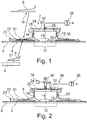
- Fig. 1 shows a sectional view of a system 2 for connecting a first component 4 and a second component 6.
- a molding tool 8 has a tool surface 10 on which the first component 4 is placed.
- the tool surface 10 is designed to be continuous, that is to say continuously. However, this could also be modified as long as it is ensured that an arrangement located thereon is airtight and can be evacuated.
- the first component 4 is, for example, a fuselage shell of a commercial aircraft, which has a first cutout 12 at the point shown. This is, for example, a window cutout and round, oval or largely square with rounded corners.
- the second component 6 is a window frame which is later located inside the finished aircraft fuselage and has a second cutout 14 which is aligned with the first cutout 12.
- the second component 6 also has a flange 16 running around the second cutout 14, which extends from the second component 6 in a direction facing away from the first component 4.
- the flange 16 roughly follows an edge of the first cutout 12 and can therefore be a section of a lateral surface of a hollow cylinder or a hollow cone.
- the second component 6 has a bearing surface 18 which, for example, lies radially outside the flange 16.
- the support surface 18 is used to produce surface contact between the second component 6 and the joining partner. This is shown here by way of example in the form of a reinforcing element 20, which is used to thicken an edge surface 21 of the first component 4 that encircles the first cutout 12.
- the support surface 18 is consequently glued to the reinforcing element 20, which, however, is glued to the edge surface 21.
- the reinforcing element 20 can, however, also be omitted if thickening is not required.
- the support surface 18 is then consequently glued to the edge surface 21.
- a layer of adhesive is present between the first component 4 and the reinforcement element 20 and between the reinforcement element 20 and the second component 6. This could be designed as a thermosetting adhesive.
- a vacuum film 22 is used, which could be glued onto the first component 4 and thereby completely covers the second component 6. After evacuation, pressure is applied to the adhesive in order to optimize the quality of the bond.
- the second component 6 has the second cutout 14, simply laying on the vacuum film 22 due to the limited contact surface does not mean that a sufficient compressive force can be produced.
- an auxiliary body 24 is provided which is placed on the flange 16 and completely covers the second cutout 14.
- the auxiliary body 24 has, for example, a circumferential groove 25 which is adapted to the shape of the flange 16.
- the groove 25 can be placed flush on the flange 16.
- the complete arrangement of the molding tool 8, the first component 4, the second component 6 and the auxiliary body 24 is covered by the vacuum film 22. This extends as far as a terminating area 23, which lies clearly outside the second component 6. After the space below has been evacuated, the entire surface determined by an outer contour of the second component 6 creates a compressive force in the direction of the mold 8.
- the auxiliary body 24 leads to the introduction of a comparatively large compressive force on the flange 16, so that the adhesive lying radially outside loaded with a predetermined compressive force and consequently subjected to a desired pressure.
- a vacuum source 26 which is shown schematically as a block, can be coupled to an opening 28 of the vacuum foil 22 and suck air from an interior 30 below the vacuum foil 22.
- the opening 28 can be in alignment with a through hole 32 of the auxiliary body 24. Alternatively, such an opening could also be integrated in the molding tool 8.
- the vacuum film 22 is applied to all of the components underneath and presses it in the direction of the tool surface 10. The adhesive is consequently subjected to a desired pressure.
- connection of the two components 4 and 6 can consequently take place outside of an autoclave.
- larger components can be processed with such a system.
- auxiliary body 24 could be additionally braced.
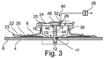
- An in Fig. 2 modified system 34 shown can be used in which, in addition to the components in Fig. 1 a schematically illustrated actuator 36 is also provided. This acts on the auxiliary body 24.
- the actuator 36 can be a hydraulic or pneumatic actuator and can be supplied with a pressurized fluid. The force exerted by the actuator 36 can be adjusted by regulating the pressure applied to the actuator 36.
- the actuator 36 can also have a spindle gear that is coupled to an electric motor. For the sake of simplicity, no fluid lines and no electrical lines that are necessary for operating the actuator 36 are shown.
- the actuator 36 is coupled to a force control unit 38 which limits a force exerted on the auxiliary body 24 by the actuator 36.
- a force measuring device can be provided which measures the force exerted on the auxiliary body 24 and controls the actuator 36 as a function thereof.
- a bolt 42 can also be used which extends into a threaded bore 44 of the molding tool 8 and is guided through a corresponding opening 46 in the auxiliary body 24.
- an additional compressive force acting on the second component 6 can be set become.
- the additional compressive force can be precisely adjusted by using a torque wrench on a screw head 48 of the bolt 42.
- a schematic, block-based illustration shows a method 50 for connecting two components 4 and 6.
- the method 50 has the step of arranging 52 the first component 4 on the tool surface 10.
- the second component 6, which has the cutout 14, is then placed 54 on the first component 4 with the inclusion of an adhesive.
- the auxiliary body 24 covering the second cutout 14 is placed 56 on the second component 6
- Auxiliary body 24 and at least one end region of the first component 4 surrounding the second component 6 is covered 58 with the vacuum film 22.
- the space 30 enclosed by the first component 4 and the vacuum film 22 is then evacuated 60.
- the vacuum film 22 is removed 62.
- the auxiliary body can also be braced 64 before the covering 58.
- an intermediate space between the first component 4 and the second component 6, in which the adhesive is located can be heated 66.
- This can also be optionally Reinforcing element 20 between the first component 4 and the second component 6 are introduced 68, so that a reinfor In particular, an edge area around the first cutout 12 takes place.
Landscapes
- Engineering & Computer Science (AREA)
- Mechanical Engineering (AREA)
- General Engineering & Computer Science (AREA)
- Aviation & Aerospace Engineering (AREA)
- Manufacturing & Machinery (AREA)
- Transportation (AREA)
- Lining Or Joining Of Plastics Or The Like (AREA)
Claims (13)
- Procédé (50) d'assemblage de deux composants, comprenant les étapes consistant à :- Disposer (52) un premier composant (4) sur une surface d'outil (10),- placer (54) un second composant (6) ayant une découpe (14) sur le premier composant (4) avec l'inclusion d'un adhésif,- placer (56) un corps auxiliaire (24) recouvrant la découpe (14) sur le deuxième composant (6),- recouvrir (58) le deuxième composant (6), le corps auxiliaire (24) et au moins une zone d'extrémité (23) du premier composant (4) entourant le deuxième composant (6) avec un film sous vide (22),- évacuer (60) l'espace (30) enfermé par le premier composant (4) et le film sous vide (22), et- retirer la feuille de vide (22) après le durcissement de l'adhésif,caractérisé en ce que
le deuxième composant (6) présente une bride (16) qui entoure la découpe (14) au moins par zones et s'étend depuis le deuxième composant (6) dans une direction opposée au premier composant (4), le corps auxiliaire (24) étant placé sur la bride (16). - Procédé (50) selon la revendication 1,
comprenant en outre l'étape consistant à chauffer (66) un espace entre le premier composant (4) et le second composant (6) dans lequel l'adhésif est situé. - Procédé (50) selon la revendication 1 ou 2,
comprenant en outre l'étape consistant à insérer (68) un élément de renforcement (20) entre le premier composant (4) et le second composant (6), dans lequel de l'adhésif est piégé entre le premier composant (4) et l'élément de renforcement (20) et entre l'élément de renforcement (20) et le second composant (6). - Procédé (50) selon l'une quelconque des revendications précédentes,
dans lequel le premier composant (4) comprend une première découpe (12), dans lequel le second composant (6) comprend une seconde découpe (14), et dans lequel le second composant (6) est placé sur le premier composant (4) de sorte que la première découpe (12) et la seconde découpe (14) sont alignées l'une avec l'autre. - Procédé (50) selon l'une quelconque des revendications précédentes,
comprenant en outre l'étape consistant à serrer (64) le corps auxiliaire (24) sur l'outil de formage (8) au moyen d'un élément exerçant une force de traction ou une force de com pression. - Procédé (50) selon la revendication 5,
dans lequel ledit serrage (64) comprend le vissage d'un boulon (42) à travers une ouverture (46) disposée dans ledit corps auxiliaire (24). - Procédé (50) selon l'une quelconque des revendications précédentes,
dans lequel le serrage (64) comprend la pression du corps auxiliaire (24) sur le second composant (6) avec un actionneur (36). - Procédé (50) selon la revendication 7,
dans lequel l'actionneur (36) est couplé à une source de vide (26) utilisée pour faire le vide (60). - Un système (2, 34, 40) pour joindre deux composants, comprenant :- un outil de formage (8),- un corps auxiliaire (24),- une feuille de vide (22),- une source de vide (26), et- un adhésif,ledit outil de formage (8) ayant une surface d'outil (10) pour recevoir un premier composant (4),
dans lequel le corps auxiliaire (24) est adapté pour être placé sur un second composant (6) tout en couvrant une découpe (14) du second composant (6),
le film sous vide (22) étant conçu pour couvrir le deuxième composant (6) placé sur le premier composant (4), y compris l'adhésif, le corps auxiliaire (24) placé sur le deuxième composant (6) et au moins une région d'extrémité du premier composant (4) qui entoure le deuxième composant (6), et
dans lequel la source de vide (26) peut être couplée à au moins une ouverture (28) dans la feuille à vide (22) ou l'outil de formage (8) de sorte qu'un espace enfermé par le premier composant (4) et la feuille à vide (22) peut être évacué.
caractérisé en ce que
le deuxième composant (6) présente une bride (16) qui entoure la découpe (14) au moins par zones et s'étend depuis le deuxième composant (6) dans une direction opposée au premier composant (4), le corps auxiliaire (24) étant placé sur la bride (16). - Système (2, 34, 40) selon la revendication 9,
dans lequel le corps auxiliaire (24) comprend un revêtement coulissant. - Système (2, 34, 40) selon la revendication 10 ou 9,
dans lequel la surface de l'outil (10) comprend un alésage fileté (44),
dans lequel le corps auxiliaire (24) a une ouverture (46) alignée avec l'alésage fileté (44) à des positions prévues du premier composant (4), du second composant (6) et du corps auxiliaire (24), et
dans lequel le système (2, 34, 40) comprend en outre un boulon (42) ayant des filets correspondant à l'alésage fileté (44) pour serrer le corps auxiliaire (24) sur l'outil de formage (8). - Système (2, 34, 40) selon l'une quelconque des revendications 9 à 11,
comprenant en outre un actionneur (36) pour presser le corps auxiliaire (24) sur le deuxième composant (6). - Système (2, 34, 40) selon la revendication 12,
comprenant en outre une unité de commande de force (38) couplée à l'actionneur (36), l'unité de commande de force (38) étant adaptée pour détecter la force appliquée par l'actionneur (36) au corps auxiliaire (24) et pour ajuster la force à une valeur prédéterminée.
Applications Claiming Priority (1)
| Application Number | Priority Date | Filing Date | Title |
|---|---|---|---|
| DE102018125979.4A DE102018125979A1 (de) | 2018-10-19 | 2018-10-19 | Verfahren und System zum Verbinden zweier Bauteile |
Publications (2)
| Publication Number | Publication Date |
|---|---|
| EP3640485A1 EP3640485A1 (fr) | 2020-04-22 |
| EP3640485B1 true EP3640485B1 (fr) | 2021-06-30 |
Family
ID=68296062
Family Applications (1)
| Application Number | Title | Priority Date | Filing Date |
|---|---|---|---|
| EP19203994.9A Active EP3640485B1 (fr) | 2018-10-19 | 2019-10-18 | Procédé et système de raccordement de deux composants |
Country Status (4)
| Country | Link |
|---|---|
| US (1) | US11787125B2 (fr) |
| EP (1) | EP3640485B1 (fr) |
| CN (1) | CN111075810A (fr) |
| DE (1) | DE102018125979A1 (fr) |
Families Citing this family (2)
| Publication number | Priority date | Publication date | Assignee | Title |
|---|---|---|---|---|
| IT202000027287A1 (it) * | 2020-11-13 | 2022-05-13 | Leonardo Spa | Metodo e attrezzatura per l'integrazione di longheroni continui aventi sezione a j in pannelli allungati di materiale composito |
| DE102023114402A1 (de) * | 2023-06-01 | 2024-12-05 | Premium Aerotec Gmbh | Verfahren zum Verbinden eines Fensterrahmens mit einer Rumpfhaut eines Luftfahrzeugs aus einem Faserverbundwerkstoff |
Family Cites Families (26)
| Publication number | Priority date | Publication date | Assignee | Title |
|---|---|---|---|---|
| US3950204A (en) * | 1972-09-29 | 1976-04-13 | Texas Instruments Incorporated | Low pressure, thin film bonding |
| US4927480A (en) * | 1989-02-27 | 1990-05-22 | Signet Armorlite, Inc. | Method and clamping device for bonding thin lens wafers |
| JPH08121442A (ja) * | 1994-10-26 | 1996-05-14 | Mitsubishi Electric Corp | 接着接合体及びその接合方法並びにリベット |
| JPH10146898A (ja) * | 1996-11-15 | 1998-06-02 | Honda Motor Co Ltd | 繊維強化複合材の成形方法 |
| US6692681B1 (en) * | 1997-01-29 | 2004-02-17 | Raytheon Aircraft Company | Method and apparatus for manufacturing composite structures |
| DE10325694B4 (de) * | 2003-06-06 | 2005-10-27 | Eads Deutschland Gmbh | Verfahren zum Verkleben von Bauteilen und insbesondere von Faserverbundbauteilen |
| US8262823B2 (en) * | 2003-09-04 | 2012-09-11 | The Boeing Company | Window skin panel and method of making same |
| US7186367B2 (en) * | 2004-05-13 | 2007-03-06 | The United States Of America As Represented By The Administrator Of The National Aeronautics And Space Administration | Double vacuum bag process for resin matrix composite manufacturing |
| DE102006007429B4 (de) * | 2006-02-17 | 2011-08-18 | Airbus Operations GmbH, 21129 | Verfahren zum autoklavfreien Verkleben von Bauteilen für Luftfahrzeuge |
| US7670527B2 (en) * | 2006-05-09 | 2010-03-02 | Lockheed Martin Corporation | Failsafe injected adhesive joint |
| JP5116282B2 (ja) * | 2006-10-31 | 2013-01-09 | 株式会社ジャムコ | 構造部材の連続製造方法 |
| US8303882B2 (en) * | 2009-02-23 | 2012-11-06 | General Electric Company | Apparatus and method of making composite material articles |
| GB0906953D0 (en) * | 2009-04-23 | 2009-06-03 | Airbus Uk Ltd | Composite structure |
| JP4906004B2 (ja) * | 2009-04-28 | 2012-03-28 | 大成プラス株式会社 | 金属合金と繊維強化プラスチックの複合体の製造方法 |
| DE102010006328A1 (de) * | 2010-01-29 | 2011-08-04 | Premium AEROTEC GmbH, 86179 | Verfahren zur Herstellung einer Klebeverbindung und Klebeverbindung sowie Anordnung zur Durchführung des Verfahrens |
| US8262841B2 (en) * | 2010-11-24 | 2012-09-11 | The Boeing Company | Methods for void-free debulking of adhesive bonded joints |
| CN103261021B (zh) * | 2010-12-28 | 2016-01-20 | 贝尔直升机泰克斯特龙公司 | 多向负载连接系统 |
| US8961732B2 (en) * | 2011-01-03 | 2015-02-24 | The Boeing Company | Method and device for compressing a composite radius |
| DE102012223863A1 (de) * | 2012-12-19 | 2014-06-26 | Bayerische Motoren Werke Aktiengesellschaft | Befestigungsvorrichtung für ein aus einem kohlenstofffaserverstärkten Kunststoff bestehendes Bauteil an einer Komponente, insbes. einer Fahrwerkskomponente eines Fahrzeugs |
| US9707705B2 (en) * | 2013-07-02 | 2017-07-18 | The Boeing Company | Vacuum bag processing of composite parts using a conformable vacuum bag assembly |
| JP5999068B2 (ja) * | 2013-10-30 | 2016-09-28 | トヨタ自動車株式会社 | 締結構造 |
| JP6332475B2 (ja) * | 2015-01-22 | 2018-05-30 | 日産自動車株式会社 | 炭素繊維強化樹脂材の締結構造 |
| US9713901B2 (en) * | 2015-05-27 | 2017-07-25 | The Boeing Company | Method to reduce residual stress in an integrally-stiffened co-bonded structure |
| US10369756B2 (en) * | 2015-08-25 | 2019-08-06 | The Boeing Company | Method of manufacturing a composite article |
| US10195819B1 (en) * | 2016-02-02 | 2019-02-05 | Fred D Donnelly | Multilayer ceramic composite and method of production |
| GB2558269A (en) * | 2016-12-23 | 2018-07-11 | Airbus Group Ltd | Joining method and apparatus |
-
2018
- 2018-10-19 DE DE102018125979.4A patent/DE102018125979A1/de not_active Ceased
-
2019
- 2019-10-14 CN CN201910972908.1A patent/CN111075810A/zh active Pending
- 2019-10-17 US US16/655,368 patent/US11787125B2/en active Active
- 2019-10-18 EP EP19203994.9A patent/EP3640485B1/fr active Active
Also Published As
| Publication number | Publication date |
|---|---|
| US11787125B2 (en) | 2023-10-17 |
| DE102018125979A1 (de) | 2020-04-23 |
| EP3640485A1 (fr) | 2020-04-22 |
| US20200122411A1 (en) | 2020-04-23 |
| CN111075810A (zh) | 2020-04-28 |
Similar Documents
| Publication | Publication Date | Title |
|---|---|---|
| DE102008001498B3 (de) | Verfahren und Umformvorrichtung zur Herstellung eines Faserverbundbauteils für die Luft- und Raumfahrt | |
| EP3105038B1 (fr) | Procédé de fabrication d'un élément composite | |
| EP2859987B1 (fr) | Composé d'éléments de construction | |
| DE102007062872A1 (de) | Verfahren zur Herstellung eines Profils aus Faserverbundwerkstoff | |
| DE102007026099A1 (de) | Vorrichtung und Verfahren zum Bearbeiten einer Faserverbundstruktur | |
| EP2481569A1 (fr) | Composant de véhicule automobile et procédé de fabrication du composant de véhicule automobile | |
| EP2408610A2 (fr) | Procédé pour au moins partiellement usiner ultérieurement ou remplacer un élément de renforcement d'une structure composite à fibres et dispositif de liaison associé | |
| DE102010050740A1 (de) | Verfahren und Vorrichtung zur Herstellung eines Flugzeugstrukturbauteils | |
| EP2185339A1 (fr) | Procede de fabrication d'un composant et composant thermoplastique renforce de fibres | |
| EP3269532B1 (fr) | Procédé d'assemblage de deux pièces à joindre en composite chargé de fibres | |
| DE102016210124A1 (de) | Verfahren zur Integration einer Hinterbaustruktur-Baugruppe in eine Struktur eines Luft- oder Raumfahrzeugs | |
| EP3640485B1 (fr) | Procédé et système de raccordement de deux composants | |
| DE102010045210B4 (de) | Vakuumaufbau zur Druckbeaufschlagung eines Bauteils während seiner Herstellung, und Verfahren zur Herstellung eines Bauteils | |
| EP3524414A1 (fr) | Tampon en mousse plastique actionnable sous vide | |
| EP3527641B1 (fr) | Film adhésif ainsi que dispositif et procédé de vérification d'un raccordement adhésif | |
| DE102014001690B4 (de) | Verfahren zum Fügen eines Metallbauteils mit einem Kunststoffbauteil | |
| DE102010029094A1 (de) | Stringerpositionierung | |
| DE102012015183A1 (de) | Fügeverbindung zwischen zwei Bauteilen, Blindniet für eine solche Fügeverbindung sowie Verfahren zur Herstellung einer solchen Fügeverbindung | |
| DE102011051301A1 (de) | Verfahren und Vorrichtung zur Herstellung einer Metall-Kunststoff-Verbindung | |
| DE102008036349B4 (de) | Verfahren und Vorrichtung zur Herstellung einer Struktur, insbesondere einer Flugzeugstruktur aus einem Faserverbundwerkstoff | |
| DE102006001494B3 (de) | Verfahren und Vorrichtung zum Herstellen einer Fügung von Bauteilen | |
| DE102006038666B4 (de) | Herstellungsverfahren für ein Werkstück aus einem Faserverbundwerkstoff und Vorrichtung zum Herstellen eines Werkstücks aus einem Faserverbundwerkstoff | |
| DE102015115788B4 (de) | Umgeschlagene Struktur und Verfahren zum Umschlagen | |
| EP3455050B1 (fr) | Procédé et dispositif pour assembler des composants | |
| DE102007004313B4 (de) | Verfahren zur Herstellung eines Bauteils für ein Luft- oder Raumfahrzeug |
Legal Events
| Date | Code | Title | Description |
|---|---|---|---|
| PUAI | Public reference made under article 153(3) epc to a published international application that has entered the european phase |
Free format text: ORIGINAL CODE: 0009012 |
|
| STAA | Information on the status of an ep patent application or granted ep patent |
Free format text: STATUS: THE APPLICATION HAS BEEN PUBLISHED |
|
| AK | Designated contracting states |
Kind code of ref document: A1 Designated state(s): AL AT BE BG CH CY CZ DE DK EE ES FI FR GB GR HR HU IE IS IT LI LT LU LV MC MK MT NL NO PL PT RO RS SE SI SK SM TR |
|
| AX | Request for extension of the european patent |
Extension state: BA ME |
|
| STAA | Information on the status of an ep patent application or granted ep patent |
Free format text: STATUS: REQUEST FOR EXAMINATION WAS MADE |
|
| 17P | Request for examination filed |
Effective date: 20201022 |
|
| RBV | Designated contracting states (corrected) |
Designated state(s): AL AT BE BG CH CY CZ DE DK EE ES FI FR GB GR HR HU IE IS IT LI LT LU LV MC MK MT NL NO PL PT RO RS SE SI SK SM TR |
|
| REG | Reference to a national code |
Ref country code: DE Ref legal event code: R079 Ref document number: 502019001721 Country of ref document: DE Free format text: PREVIOUS MAIN CLASS: F16B0011000000 Ipc: B64C0001140000 |
|
| RIC1 | Information provided on ipc code assigned before grant |
Ipc: B64C 1/14 20060101AFI20210305BHEP Ipc: B64F 5/10 20170101ALI20210305BHEP Ipc: F16B 11/00 20060101ALI20210305BHEP Ipc: B29C 65/00 20060101ALI20210305BHEP Ipc: B29C 65/48 20060101ALI20210305BHEP Ipc: B29L 12/00 20060101ALN20210305BHEP Ipc: B29L 31/30 20060101ALN20210305BHEP Ipc: B29L 31/00 20060101ALN20210305BHEP |
|
| GRAP | Despatch of communication of intention to grant a patent |
Free format text: ORIGINAL CODE: EPIDOSNIGR1 |
|
| STAA | Information on the status of an ep patent application or granted ep patent |
Free format text: STATUS: GRANT OF PATENT IS INTENDED |
|
| RIC1 | Information provided on ipc code assigned before grant |
Ipc: B64C 1/14 20060101AFI20210319BHEP Ipc: B64F 5/10 20170101ALI20210319BHEP Ipc: F16B 11/00 20060101ALI20210319BHEP Ipc: B29C 65/00 20060101ALI20210319BHEP Ipc: B29C 65/48 20060101ALI20210319BHEP Ipc: B29L 12/00 20060101ALN20210319BHEP Ipc: B29L 31/30 20060101ALN20210319BHEP Ipc: B29L 31/00 20060101ALN20210319BHEP |
|
| RIC1 | Information provided on ipc code assigned before grant |
Ipc: B64C 1/14 20060101AFI20210326BHEP Ipc: B64F 5/10 20170101ALI20210326BHEP Ipc: F16B 11/00 20060101ALI20210326BHEP Ipc: B29C 65/00 20060101ALI20210326BHEP Ipc: B29C 65/48 20060101ALI20210326BHEP Ipc: B29L 12/00 20060101ALN20210326BHEP Ipc: B29L 31/30 20060101ALN20210326BHEP Ipc: B29L 31/00 20060101ALN20210326BHEP |
|
| INTG | Intention to grant announced |
Effective date: 20210422 |
|
| GRAS | Grant fee paid |
Free format text: ORIGINAL CODE: EPIDOSNIGR3 |
|
| GRAA | (expected) grant |
Free format text: ORIGINAL CODE: 0009210 |
|
| STAA | Information on the status of an ep patent application or granted ep patent |
Free format text: STATUS: THE PATENT HAS BEEN GRANTED |
|
| AK | Designated contracting states |
Kind code of ref document: B1 Designated state(s): AL AT BE BG CH CY CZ DE DK EE ES FI FR GB GR HR HU IE IS IT LI LT LU LV MC MK MT NL NO PL PT RO RS SE SI SK SM TR |
|
| REG | Reference to a national code |
Ref country code: CH Ref legal event code: EP |
|
| REG | Reference to a national code |
Ref country code: AT Ref legal event code: REF Ref document number: 1406140 Country of ref document: AT Kind code of ref document: T Effective date: 20210715 |
|
| REG | Reference to a national code |
Ref country code: DE Ref legal event code: R096 Ref document number: 502019001721 Country of ref document: DE |
|
| REG | Reference to a national code |
Ref country code: IE Ref legal event code: FG4D Free format text: LANGUAGE OF EP DOCUMENT: GERMAN |
|
| REG | Reference to a national code |
Ref country code: LT Ref legal event code: MG9D |
|
| PG25 | Lapsed in a contracting state [announced via postgrant information from national office to epo] |
Ref country code: FI Free format text: LAPSE BECAUSE OF FAILURE TO SUBMIT A TRANSLATION OF THE DESCRIPTION OR TO PAY THE FEE WITHIN THE PRESCRIBED TIME-LIMIT Effective date: 20210630 Ref country code: HR Free format text: LAPSE BECAUSE OF FAILURE TO SUBMIT A TRANSLATION OF THE DESCRIPTION OR TO PAY THE FEE WITHIN THE PRESCRIBED TIME-LIMIT Effective date: 20210630 Ref country code: BG Free format text: LAPSE BECAUSE OF FAILURE TO SUBMIT A TRANSLATION OF THE DESCRIPTION OR TO PAY THE FEE WITHIN THE PRESCRIBED TIME-LIMIT Effective date: 20210930 |
|
| REG | Reference to a national code |
Ref country code: NL Ref legal event code: MP Effective date: 20210630 |
|
| PG25 | Lapsed in a contracting state [announced via postgrant information from national office to epo] |
Ref country code: SE Free format text: LAPSE BECAUSE OF FAILURE TO SUBMIT A TRANSLATION OF THE DESCRIPTION OR TO PAY THE FEE WITHIN THE PRESCRIBED TIME-LIMIT Effective date: 20210630 Ref country code: RS Free format text: LAPSE BECAUSE OF FAILURE TO SUBMIT A TRANSLATION OF THE DESCRIPTION OR TO PAY THE FEE WITHIN THE PRESCRIBED TIME-LIMIT Effective date: 20210630 Ref country code: LV Free format text: LAPSE BECAUSE OF FAILURE TO SUBMIT A TRANSLATION OF THE DESCRIPTION OR TO PAY THE FEE WITHIN THE PRESCRIBED TIME-LIMIT Effective date: 20210630 Ref country code: NO Free format text: LAPSE BECAUSE OF FAILURE TO SUBMIT A TRANSLATION OF THE DESCRIPTION OR TO PAY THE FEE WITHIN THE PRESCRIBED TIME-LIMIT Effective date: 20210930 Ref country code: GR Free format text: LAPSE BECAUSE OF FAILURE TO SUBMIT A TRANSLATION OF THE DESCRIPTION OR TO PAY THE FEE WITHIN THE PRESCRIBED TIME-LIMIT Effective date: 20211001 |
|
| PG25 | Lapsed in a contracting state [announced via postgrant information from national office to epo] |
Ref country code: ES Free format text: LAPSE BECAUSE OF FAILURE TO SUBMIT A TRANSLATION OF THE DESCRIPTION OR TO PAY THE FEE WITHIN THE PRESCRIBED TIME-LIMIT Effective date: 20210630 Ref country code: EE Free format text: LAPSE BECAUSE OF FAILURE TO SUBMIT A TRANSLATION OF THE DESCRIPTION OR TO PAY THE FEE WITHIN THE PRESCRIBED TIME-LIMIT Effective date: 20210630 Ref country code: SK Free format text: LAPSE BECAUSE OF FAILURE TO SUBMIT A TRANSLATION OF THE DESCRIPTION OR TO PAY THE FEE WITHIN THE PRESCRIBED TIME-LIMIT Effective date: 20210630 Ref country code: CZ Free format text: LAPSE BECAUSE OF FAILURE TO SUBMIT A TRANSLATION OF THE DESCRIPTION OR TO PAY THE FEE WITHIN THE PRESCRIBED TIME-LIMIT Effective date: 20210630 Ref country code: RO Free format text: LAPSE BECAUSE OF FAILURE TO SUBMIT A TRANSLATION OF THE DESCRIPTION OR TO PAY THE FEE WITHIN THE PRESCRIBED TIME-LIMIT Effective date: 20210630 Ref country code: NL Free format text: LAPSE BECAUSE OF FAILURE TO SUBMIT A TRANSLATION OF THE DESCRIPTION OR TO PAY THE FEE WITHIN THE PRESCRIBED TIME-LIMIT Effective date: 20210630 Ref country code: PT Free format text: LAPSE BECAUSE OF FAILURE TO SUBMIT A TRANSLATION OF THE DESCRIPTION OR TO PAY THE FEE WITHIN THE PRESCRIBED TIME-LIMIT Effective date: 20211102 Ref country code: SM Free format text: LAPSE BECAUSE OF FAILURE TO SUBMIT A TRANSLATION OF THE DESCRIPTION OR TO PAY THE FEE WITHIN THE PRESCRIBED TIME-LIMIT Effective date: 20210630 |
|
| PG25 | Lapsed in a contracting state [announced via postgrant information from national office to epo] |
Ref country code: PL Free format text: LAPSE BECAUSE OF FAILURE TO SUBMIT A TRANSLATION OF THE DESCRIPTION OR TO PAY THE FEE WITHIN THE PRESCRIBED TIME-LIMIT Effective date: 20210630 |
|
| REG | Reference to a national code |
Ref country code: DE Ref legal event code: R097 Ref document number: 502019001721 Country of ref document: DE |
|
| PG25 | Lapsed in a contracting state [announced via postgrant information from national office to epo] |
Ref country code: DK Free format text: LAPSE BECAUSE OF FAILURE TO SUBMIT A TRANSLATION OF THE DESCRIPTION OR TO PAY THE FEE WITHIN THE PRESCRIBED TIME-LIMIT Effective date: 20210630 |
|
| PLBE | No opposition filed within time limit |
Free format text: ORIGINAL CODE: 0009261 |
|
| STAA | Information on the status of an ep patent application or granted ep patent |
Free format text: STATUS: NO OPPOSITION FILED WITHIN TIME LIMIT |
|
| PG25 | Lapsed in a contracting state [announced via postgrant information from national office to epo] |
Ref country code: AL Free format text: LAPSE BECAUSE OF FAILURE TO SUBMIT A TRANSLATION OF THE DESCRIPTION OR TO PAY THE FEE WITHIN THE PRESCRIBED TIME-LIMIT Effective date: 20210630 |
|
| 26N | No opposition filed |
Effective date: 20220331 |
|
| REG | Reference to a national code |
Ref country code: BE Ref legal event code: MM Effective date: 20211031 |
|
| PG25 | Lapsed in a contracting state [announced via postgrant information from national office to epo] |
Ref country code: MC Free format text: LAPSE BECAUSE OF FAILURE TO SUBMIT A TRANSLATION OF THE DESCRIPTION OR TO PAY THE FEE WITHIN THE PRESCRIBED TIME-LIMIT Effective date: 20210630 |
|
| PG25 | Lapsed in a contracting state [announced via postgrant information from national office to epo] |
Ref country code: LU Free format text: LAPSE BECAUSE OF NON-PAYMENT OF DUE FEES Effective date: 20211018 Ref country code: IT Free format text: LAPSE BECAUSE OF FAILURE TO SUBMIT A TRANSLATION OF THE DESCRIPTION OR TO PAY THE FEE WITHIN THE PRESCRIBED TIME-LIMIT Effective date: 20210630 Ref country code: BE Free format text: LAPSE BECAUSE OF NON-PAYMENT OF DUE FEES Effective date: 20211031 |
|
| PG25 | Lapsed in a contracting state [announced via postgrant information from national office to epo] |
Ref country code: IE Free format text: LAPSE BECAUSE OF NON-PAYMENT OF DUE FEES Effective date: 20211018 |
|
| PG25 | Lapsed in a contracting state [announced via postgrant information from national office to epo] |
Ref country code: LT Free format text: LAPSE BECAUSE OF FAILURE TO SUBMIT A TRANSLATION OF THE DESCRIPTION OR TO PAY THE FEE WITHIN THE PRESCRIBED TIME-LIMIT Effective date: 20210630 |
|
| REG | Reference to a national code |
Ref country code: CH Ref legal event code: PL |
|
| PG25 | Lapsed in a contracting state [announced via postgrant information from national office to epo] |
Ref country code: CY Free format text: LAPSE BECAUSE OF FAILURE TO SUBMIT A TRANSLATION OF THE DESCRIPTION OR TO PAY THE FEE WITHIN THE PRESCRIBED TIME-LIMIT Effective date: 20210630 |
|
| PG25 | Lapsed in a contracting state [announced via postgrant information from national office to epo] |
Ref country code: LI Free format text: LAPSE BECAUSE OF NON-PAYMENT OF DUE FEES Effective date: 20221031 Ref country code: HU Free format text: LAPSE BECAUSE OF FAILURE TO SUBMIT A TRANSLATION OF THE DESCRIPTION OR TO PAY THE FEE WITHIN THE PRESCRIBED TIME-LIMIT; INVALID AB INITIO Effective date: 20191018 Ref country code: CH Free format text: LAPSE BECAUSE OF NON-PAYMENT OF DUE FEES Effective date: 20221031 |
|
| PG25 | Lapsed in a contracting state [announced via postgrant information from national office to epo] |
Ref country code: MK Free format text: LAPSE BECAUSE OF FAILURE TO SUBMIT A TRANSLATION OF THE DESCRIPTION OR TO PAY THE FEE WITHIN THE PRESCRIBED TIME-LIMIT Effective date: 20210630 |
|
| PG25 | Lapsed in a contracting state [announced via postgrant information from national office to epo] |
Ref country code: TR Free format text: LAPSE BECAUSE OF FAILURE TO SUBMIT A TRANSLATION OF THE DESCRIPTION OR TO PAY THE FEE WITHIN THE PRESCRIBED TIME-LIMIT Effective date: 20210630 |
|
| PG25 | Lapsed in a contracting state [announced via postgrant information from national office to epo] |
Ref country code: MT Free format text: LAPSE BECAUSE OF FAILURE TO SUBMIT A TRANSLATION OF THE DESCRIPTION OR TO PAY THE FEE WITHIN THE PRESCRIBED TIME-LIMIT Effective date: 20210630 |
|
| REG | Reference to a national code |
Ref country code: AT Ref legal event code: MM01 Ref document number: 1406140 Country of ref document: AT Kind code of ref document: T Effective date: 20241018 |
|
| PGFP | Annual fee paid to national office [announced via postgrant information from national office to epo] |
Ref country code: DE Payment date: 20251021 Year of fee payment: 7 |
|
| PGFP | Annual fee paid to national office [announced via postgrant information from national office to epo] |
Ref country code: GB Payment date: 20251022 Year of fee payment: 7 |
|
| PG25 | Lapsed in a contracting state [announced via postgrant information from national office to epo] |
Ref country code: AT Free format text: LAPSE BECAUSE OF NON-PAYMENT OF DUE FEES Effective date: 20241018 |
|
| PGFP | Annual fee paid to national office [announced via postgrant information from national office to epo] |
Ref country code: FR Payment date: 20251030 Year of fee payment: 7 |
|
| PGFP | Annual fee paid to national office [announced via postgrant information from national office to epo] |
Ref country code: AT Payment date: 20260410 Year of fee payment: 5 |