EP3643958A1 - Ensemble comprenant un capotage de protection et une bouteille de gaz avec un dispositif indicateur de pression ou d'autonomie en position haute - Google Patents
Ensemble comprenant un capotage de protection et une bouteille de gaz avec un dispositif indicateur de pression ou d'autonomie en position haute Download PDFInfo
- Publication number
- EP3643958A1 EP3643958A1 EP19208588.4A EP19208588A EP3643958A1 EP 3643958 A1 EP3643958 A1 EP 3643958A1 EP 19208588 A EP19208588 A EP 19208588A EP 3643958 A1 EP3643958 A1 EP 3643958A1
- Authority
- EP
- European Patent Office
- Prior art keywords
- gas
- bottle
- pressure
- assembly according
- protective cover
- Prior art date
- Legal status (The legal status is an assumption and is not a legal conclusion. Google has not performed a legal analysis and makes no representation as to the accuracy of the status listed.)
- Granted
Links
Images


Classifications
-
- F—MECHANICAL ENGINEERING; LIGHTING; HEATING; WEAPONS; BLASTING
- F17—STORING OR DISTRIBUTING GASES OR LIQUIDS
- F17C—VESSELS FOR CONTAINING OR STORING COMPRESSED, LIQUEFIED OR SOLIDIFIED GASES; FIXED-CAPACITY GAS-HOLDERS; FILLING VESSELS WITH, OR DISCHARGING FROM VESSELS, COMPRESSED, LIQUEFIED, OR SOLIDIFIED GASES
- F17C13/00—Details of vessels or of the filling or discharging of vessels
- F17C13/02—Special adaptations of indicating, measuring, or monitoring equipment
- F17C13/025—Special adaptations of indicating, measuring, or monitoring equipment having the pressure as the parameter
-
- F—MECHANICAL ENGINEERING; LIGHTING; HEATING; WEAPONS; BLASTING
- F17—STORING OR DISTRIBUTING GASES OR LIQUIDS
- F17C—VESSELS FOR CONTAINING OR STORING COMPRESSED, LIQUEFIED OR SOLIDIFIED GASES; FIXED-CAPACITY GAS-HOLDERS; FILLING VESSELS WITH, OR DISCHARGING FROM VESSELS, COMPRESSED, LIQUEFIED, OR SOLIDIFIED GASES
- F17C1/00—Pressure vessels, e.g. gas cylinder, gas tank, replaceable cartridge
-
- F—MECHANICAL ENGINEERING; LIGHTING; HEATING; WEAPONS; BLASTING
- F17—STORING OR DISTRIBUTING GASES OR LIQUIDS
- F17C—VESSELS FOR CONTAINING OR STORING COMPRESSED, LIQUEFIED OR SOLIDIFIED GASES; FIXED-CAPACITY GAS-HOLDERS; FILLING VESSELS WITH, OR DISCHARGING FROM VESSELS, COMPRESSED, LIQUEFIED, OR SOLIDIFIED GASES
- F17C13/00—Details of vessels or of the filling or discharging of vessels
- F17C13/002—Details of vessels or of the filling or discharging of vessels for vessels under pressure
-
- F—MECHANICAL ENGINEERING; LIGHTING; HEATING; WEAPONS; BLASTING
- F17—STORING OR DISTRIBUTING GASES OR LIQUIDS
- F17C—VESSELS FOR CONTAINING OR STORING COMPRESSED, LIQUEFIED OR SOLIDIFIED GASES; FIXED-CAPACITY GAS-HOLDERS; FILLING VESSELS WITH, OR DISCHARGING FROM VESSELS, COMPRESSED, LIQUEFIED, OR SOLIDIFIED GASES
- F17C2201/00—Vessel construction, in particular geometry, arrangement or size
- F17C2201/01—Shape
- F17C2201/0104—Shape cylindrical
-
- F—MECHANICAL ENGINEERING; LIGHTING; HEATING; WEAPONS; BLASTING
- F17—STORING OR DISTRIBUTING GASES OR LIQUIDS
- F17C—VESSELS FOR CONTAINING OR STORING COMPRESSED, LIQUEFIED OR SOLIDIFIED GASES; FIXED-CAPACITY GAS-HOLDERS; FILLING VESSELS WITH, OR DISCHARGING FROM VESSELS, COMPRESSED, LIQUEFIED, OR SOLIDIFIED GASES
- F17C2201/00—Vessel construction, in particular geometry, arrangement or size
- F17C2201/03—Orientation
- F17C2201/032—Orientation with substantially vertical main axis
-
- F—MECHANICAL ENGINEERING; LIGHTING; HEATING; WEAPONS; BLASTING
- F17—STORING OR DISTRIBUTING GASES OR LIQUIDS
- F17C—VESSELS FOR CONTAINING OR STORING COMPRESSED, LIQUEFIED OR SOLIDIFIED GASES; FIXED-CAPACITY GAS-HOLDERS; FILLING VESSELS WITH, OR DISCHARGING FROM VESSELS, COMPRESSED, LIQUEFIED, OR SOLIDIFIED GASES
- F17C2201/00—Vessel construction, in particular geometry, arrangement or size
- F17C2201/05—Size
- F17C2201/058—Size portable (<30 l)
-
- F—MECHANICAL ENGINEERING; LIGHTING; HEATING; WEAPONS; BLASTING
- F17—STORING OR DISTRIBUTING GASES OR LIQUIDS
- F17C—VESSELS FOR CONTAINING OR STORING COMPRESSED, LIQUEFIED OR SOLIDIFIED GASES; FIXED-CAPACITY GAS-HOLDERS; FILLING VESSELS WITH, OR DISCHARGING FROM VESSELS, COMPRESSED, LIQUEFIED, OR SOLIDIFIED GASES
- F17C2203/00—Vessel construction, in particular walls or details thereof
- F17C2203/06—Materials for walls or layers thereof; Properties or structures of walls or their materials
- F17C2203/0634—Materials for walls or layers thereof
- F17C2203/0636—Metals
-
- F—MECHANICAL ENGINEERING; LIGHTING; HEATING; WEAPONS; BLASTING
- F17—STORING OR DISTRIBUTING GASES OR LIQUIDS
- F17C—VESSELS FOR CONTAINING OR STORING COMPRESSED, LIQUEFIED OR SOLIDIFIED GASES; FIXED-CAPACITY GAS-HOLDERS; FILLING VESSELS WITH, OR DISCHARGING FROM VESSELS, COMPRESSED, LIQUEFIED, OR SOLIDIFIED GASES
- F17C2203/00—Vessel construction, in particular walls or details thereof
- F17C2203/06—Materials for walls or layers thereof; Properties or structures of walls or their materials
- F17C2203/0634—Materials for walls or layers thereof
- F17C2203/0636—Metals
- F17C2203/0639—Steels
-
- F—MECHANICAL ENGINEERING; LIGHTING; HEATING; WEAPONS; BLASTING
- F17—STORING OR DISTRIBUTING GASES OR LIQUIDS
- F17C—VESSELS FOR CONTAINING OR STORING COMPRESSED, LIQUEFIED OR SOLIDIFIED GASES; FIXED-CAPACITY GAS-HOLDERS; FILLING VESSELS WITH, OR DISCHARGING FROM VESSELS, COMPRESSED, LIQUEFIED, OR SOLIDIFIED GASES
- F17C2203/00—Vessel construction, in particular walls or details thereof
- F17C2203/06—Materials for walls or layers thereof; Properties or structures of walls or their materials
- F17C2203/0634—Materials for walls or layers thereof
- F17C2203/0636—Metals
- F17C2203/0646—Aluminium
-
- F—MECHANICAL ENGINEERING; LIGHTING; HEATING; WEAPONS; BLASTING
- F17—STORING OR DISTRIBUTING GASES OR LIQUIDS
- F17C—VESSELS FOR CONTAINING OR STORING COMPRESSED, LIQUEFIED OR SOLIDIFIED GASES; FIXED-CAPACITY GAS-HOLDERS; FILLING VESSELS WITH, OR DISCHARGING FROM VESSELS, COMPRESSED, LIQUEFIED, OR SOLIDIFIED GASES
- F17C2203/00—Vessel construction, in particular walls or details thereof
- F17C2203/06—Materials for walls or layers thereof; Properties or structures of walls or their materials
- F17C2203/0634—Materials for walls or layers thereof
- F17C2203/0658—Synthetics
-
- F—MECHANICAL ENGINEERING; LIGHTING; HEATING; WEAPONS; BLASTING
- F17—STORING OR DISTRIBUTING GASES OR LIQUIDS
- F17C—VESSELS FOR CONTAINING OR STORING COMPRESSED, LIQUEFIED OR SOLIDIFIED GASES; FIXED-CAPACITY GAS-HOLDERS; FILLING VESSELS WITH, OR DISCHARGING FROM VESSELS, COMPRESSED, LIQUEFIED, OR SOLIDIFIED GASES
- F17C2203/00—Vessel construction, in particular walls or details thereof
- F17C2203/06—Materials for walls or layers thereof; Properties or structures of walls or their materials
- F17C2203/0634—Materials for walls or layers thereof
- F17C2203/0658—Synthetics
- F17C2203/0663—Synthetics in form of fibers or filaments
-
- F—MECHANICAL ENGINEERING; LIGHTING; HEATING; WEAPONS; BLASTING
- F17—STORING OR DISTRIBUTING GASES OR LIQUIDS
- F17C—VESSELS FOR CONTAINING OR STORING COMPRESSED, LIQUEFIED OR SOLIDIFIED GASES; FIXED-CAPACITY GAS-HOLDERS; FILLING VESSELS WITH, OR DISCHARGING FROM VESSELS, COMPRESSED, LIQUEFIED, OR SOLIDIFIED GASES
- F17C2205/00—Vessel construction, in particular mounting arrangements, attachments or identifications means
- F17C2205/01—Mounting arrangements
- F17C2205/0153—Details of mounting arrangements
- F17C2205/0157—Details of mounting arrangements for transport
- F17C2205/0165—Details of mounting arrangements for transport with handgrip
-
- F—MECHANICAL ENGINEERING; LIGHTING; HEATING; WEAPONS; BLASTING
- F17—STORING OR DISTRIBUTING GASES OR LIQUIDS
- F17C—VESSELS FOR CONTAINING OR STORING COMPRESSED, LIQUEFIED OR SOLIDIFIED GASES; FIXED-CAPACITY GAS-HOLDERS; FILLING VESSELS WITH, OR DISCHARGING FROM VESSELS, COMPRESSED, LIQUEFIED, OR SOLIDIFIED GASES
- F17C2205/00—Vessel construction, in particular mounting arrangements, attachments or identifications means
- F17C2205/01—Mounting arrangements
- F17C2205/0153—Details of mounting arrangements
- F17C2205/0192—Details of mounting arrangements with external bearing means
-
- F—MECHANICAL ENGINEERING; LIGHTING; HEATING; WEAPONS; BLASTING
- F17—STORING OR DISTRIBUTING GASES OR LIQUIDS
- F17C—VESSELS FOR CONTAINING OR STORING COMPRESSED, LIQUEFIED OR SOLIDIFIED GASES; FIXED-CAPACITY GAS-HOLDERS; FILLING VESSELS WITH, OR DISCHARGING FROM VESSELS, COMPRESSED, LIQUEFIED, OR SOLIDIFIED GASES
- F17C2205/00—Vessel construction, in particular mounting arrangements, attachments or identifications means
- F17C2205/03—Fluid connections, filters, valves, closure means or other attachments
- F17C2205/0302—Fittings, valves, filters, or components in connection with the gas storage device
- F17C2205/0308—Protective caps
-
- F—MECHANICAL ENGINEERING; LIGHTING; HEATING; WEAPONS; BLASTING
- F17—STORING OR DISTRIBUTING GASES OR LIQUIDS
- F17C—VESSELS FOR CONTAINING OR STORING COMPRESSED, LIQUEFIED OR SOLIDIFIED GASES; FIXED-CAPACITY GAS-HOLDERS; FILLING VESSELS WITH, OR DISCHARGING FROM VESSELS, COMPRESSED, LIQUEFIED, OR SOLIDIFIED GASES
- F17C2205/00—Vessel construction, in particular mounting arrangements, attachments or identifications means
- F17C2205/03—Fluid connections, filters, valves, closure means or other attachments
- F17C2205/0302—Fittings, valves, filters, or components in connection with the gas storage device
- F17C2205/0323—Valves
- F17C2205/0329—Valves manually actuated
-
- F—MECHANICAL ENGINEERING; LIGHTING; HEATING; WEAPONS; BLASTING
- F17—STORING OR DISTRIBUTING GASES OR LIQUIDS
- F17C—VESSELS FOR CONTAINING OR STORING COMPRESSED, LIQUEFIED OR SOLIDIFIED GASES; FIXED-CAPACITY GAS-HOLDERS; FILLING VESSELS WITH, OR DISCHARGING FROM VESSELS, COMPRESSED, LIQUEFIED, OR SOLIDIFIED GASES
- F17C2205/00—Vessel construction, in particular mounting arrangements, attachments or identifications means
- F17C2205/03—Fluid connections, filters, valves, closure means or other attachments
- F17C2205/0302—Fittings, valves, filters, or components in connection with the gas storage device
- F17C2205/0338—Pressure regulators
-
- F—MECHANICAL ENGINEERING; LIGHTING; HEATING; WEAPONS; BLASTING
- F17—STORING OR DISTRIBUTING GASES OR LIQUIDS
- F17C—VESSELS FOR CONTAINING OR STORING COMPRESSED, LIQUEFIED OR SOLIDIFIED GASES; FIXED-CAPACITY GAS-HOLDERS; FILLING VESSELS WITH, OR DISCHARGING FROM VESSELS, COMPRESSED, LIQUEFIED, OR SOLIDIFIED GASES
- F17C2205/00—Vessel construction, in particular mounting arrangements, attachments or identifications means
- F17C2205/03—Fluid connections, filters, valves, closure means or other attachments
- F17C2205/0388—Arrangement of valves, regulators, filters
- F17C2205/0394—Arrangement of valves, regulators, filters in direct contact with the pressure vessel
-
- F—MECHANICAL ENGINEERING; LIGHTING; HEATING; WEAPONS; BLASTING
- F17—STORING OR DISTRIBUTING GASES OR LIQUIDS
- F17C—VESSELS FOR CONTAINING OR STORING COMPRESSED, LIQUEFIED OR SOLIDIFIED GASES; FIXED-CAPACITY GAS-HOLDERS; FILLING VESSELS WITH, OR DISCHARGING FROM VESSELS, COMPRESSED, LIQUEFIED, OR SOLIDIFIED GASES
- F17C2221/00—Handled fluid, in particular type of fluid
- F17C2221/01—Pure fluids
- F17C2221/011—Oxygen
-
- F—MECHANICAL ENGINEERING; LIGHTING; HEATING; WEAPONS; BLASTING
- F17—STORING OR DISTRIBUTING GASES OR LIQUIDS
- F17C—VESSELS FOR CONTAINING OR STORING COMPRESSED, LIQUEFIED OR SOLIDIFIED GASES; FIXED-CAPACITY GAS-HOLDERS; FILLING VESSELS WITH, OR DISCHARGING FROM VESSELS, COMPRESSED, LIQUEFIED, OR SOLIDIFIED GASES
- F17C2221/00—Handled fluid, in particular type of fluid
- F17C2221/03—Mixtures
-
- F—MECHANICAL ENGINEERING; LIGHTING; HEATING; WEAPONS; BLASTING
- F17—STORING OR DISTRIBUTING GASES OR LIQUIDS
- F17C—VESSELS FOR CONTAINING OR STORING COMPRESSED, LIQUEFIED OR SOLIDIFIED GASES; FIXED-CAPACITY GAS-HOLDERS; FILLING VESSELS WITH, OR DISCHARGING FROM VESSELS, COMPRESSED, LIQUEFIED, OR SOLIDIFIED GASES
- F17C2221/00—Handled fluid, in particular type of fluid
- F17C2221/03—Mixtures
- F17C2221/031—Air
-
- F—MECHANICAL ENGINEERING; LIGHTING; HEATING; WEAPONS; BLASTING
- F17—STORING OR DISTRIBUTING GASES OR LIQUIDS
- F17C—VESSELS FOR CONTAINING OR STORING COMPRESSED, LIQUEFIED OR SOLIDIFIED GASES; FIXED-CAPACITY GAS-HOLDERS; FILLING VESSELS WITH, OR DISCHARGING FROM VESSELS, COMPRESSED, LIQUEFIED, OR SOLIDIFIED GASES
- F17C2223/00—Handled fluid before transfer, i.e. state of fluid when stored in the vessel or before transfer from the vessel
- F17C2223/01—Handled fluid before transfer, i.e. state of fluid when stored in the vessel or before transfer from the vessel characterised by the phase
- F17C2223/0107—Single phase
- F17C2223/0123—Single phase gaseous, e.g. CNG, GNC
-
- F—MECHANICAL ENGINEERING; LIGHTING; HEATING; WEAPONS; BLASTING
- F17—STORING OR DISTRIBUTING GASES OR LIQUIDS
- F17C—VESSELS FOR CONTAINING OR STORING COMPRESSED, LIQUEFIED OR SOLIDIFIED GASES; FIXED-CAPACITY GAS-HOLDERS; FILLING VESSELS WITH, OR DISCHARGING FROM VESSELS, COMPRESSED, LIQUEFIED, OR SOLIDIFIED GASES
- F17C2223/00—Handled fluid before transfer, i.e. state of fluid when stored in the vessel or before transfer from the vessel
- F17C2223/03—Handled fluid before transfer, i.e. state of fluid when stored in the vessel or before transfer from the vessel characterised by the pressure level
- F17C2223/035—High pressure (>10 bar)
-
- F—MECHANICAL ENGINEERING; LIGHTING; HEATING; WEAPONS; BLASTING
- F17—STORING OR DISTRIBUTING GASES OR LIQUIDS
- F17C—VESSELS FOR CONTAINING OR STORING COMPRESSED, LIQUEFIED OR SOLIDIFIED GASES; FIXED-CAPACITY GAS-HOLDERS; FILLING VESSELS WITH, OR DISCHARGING FROM VESSELS, COMPRESSED, LIQUEFIED, OR SOLIDIFIED GASES
- F17C2223/00—Handled fluid before transfer, i.e. state of fluid when stored in the vessel or before transfer from the vessel
- F17C2223/03—Handled fluid before transfer, i.e. state of fluid when stored in the vessel or before transfer from the vessel characterised by the pressure level
- F17C2223/036—Very high pressure (>80 bar)
-
- F—MECHANICAL ENGINEERING; LIGHTING; HEATING; WEAPONS; BLASTING
- F17—STORING OR DISTRIBUTING GASES OR LIQUIDS
- F17C—VESSELS FOR CONTAINING OR STORING COMPRESSED, LIQUEFIED OR SOLIDIFIED GASES; FIXED-CAPACITY GAS-HOLDERS; FILLING VESSELS WITH, OR DISCHARGING FROM VESSELS, COMPRESSED, LIQUEFIED, OR SOLIDIFIED GASES
- F17C2250/00—Accessories; Control means; Indicating, measuring or monitoring of parameters
- F17C2250/04—Indicating or measuring of parameters as input values
- F17C2250/0404—Parameters indicated or measured
- F17C2250/043—Pressure
-
- F—MECHANICAL ENGINEERING; LIGHTING; HEATING; WEAPONS; BLASTING
- F17—STORING OR DISTRIBUTING GASES OR LIQUIDS
- F17C—VESSELS FOR CONTAINING OR STORING COMPRESSED, LIQUEFIED OR SOLIDIFIED GASES; FIXED-CAPACITY GAS-HOLDERS; FILLING VESSELS WITH, OR DISCHARGING FROM VESSELS, COMPRESSED, LIQUEFIED, OR SOLIDIFIED GASES
- F17C2250/00—Accessories; Control means; Indicating, measuring or monitoring of parameters
- F17C2250/04—Indicating or measuring of parameters as input values
- F17C2250/0404—Parameters indicated or measured
- F17C2250/0473—Time or time periods
-
- F—MECHANICAL ENGINEERING; LIGHTING; HEATING; WEAPONS; BLASTING
- F17—STORING OR DISTRIBUTING GASES OR LIQUIDS
- F17C—VESSELS FOR CONTAINING OR STORING COMPRESSED, LIQUEFIED OR SOLIDIFIED GASES; FIXED-CAPACITY GAS-HOLDERS; FILLING VESSELS WITH, OR DISCHARGING FROM VESSELS, COMPRESSED, LIQUEFIED, OR SOLIDIFIED GASES
- F17C2250/00—Accessories; Control means; Indicating, measuring or monitoring of parameters
- F17C2250/04—Indicating or measuring of parameters as input values
- F17C2250/0486—Indicating or measuring characterised by the location
- F17C2250/0491—Parameters measured at or inside the vessel
-
- F—MECHANICAL ENGINEERING; LIGHTING; HEATING; WEAPONS; BLASTING
- F17—STORING OR DISTRIBUTING GASES OR LIQUIDS
- F17C—VESSELS FOR CONTAINING OR STORING COMPRESSED, LIQUEFIED OR SOLIDIFIED GASES; FIXED-CAPACITY GAS-HOLDERS; FILLING VESSELS WITH, OR DISCHARGING FROM VESSELS, COMPRESSED, LIQUEFIED, OR SOLIDIFIED GASES
- F17C2250/00—Accessories; Control means; Indicating, measuring or monitoring of parameters
- F17C2250/04—Indicating or measuring of parameters as input values
- F17C2250/0486—Indicating or measuring characterised by the location
- F17C2250/0495—Indicating or measuring characterised by the location the indicated parameter is a converted measured parameter
-
- F—MECHANICAL ENGINEERING; LIGHTING; HEATING; WEAPONS; BLASTING
- F17—STORING OR DISTRIBUTING GASES OR LIQUIDS
- F17C—VESSELS FOR CONTAINING OR STORING COMPRESSED, LIQUEFIED OR SOLIDIFIED GASES; FIXED-CAPACITY GAS-HOLDERS; FILLING VESSELS WITH, OR DISCHARGING FROM VESSELS, COMPRESSED, LIQUEFIED, OR SOLIDIFIED GASES
- F17C2270/00—Applications
- F17C2270/02—Applications for medical applications
-
- F—MECHANICAL ENGINEERING; LIGHTING; HEATING; WEAPONS; BLASTING
- F17—STORING OR DISTRIBUTING GASES OR LIQUIDS
- F17C—VESSELS FOR CONTAINING OR STORING COMPRESSED, LIQUEFIED OR SOLIDIFIED GASES; FIXED-CAPACITY GAS-HOLDERS; FILLING VESSELS WITH, OR DISCHARGING FROM VESSELS, COMPRESSED, LIQUEFIED, OR SOLIDIFIED GASES
- F17C2270/00—Applications
- F17C2270/02—Applications for medical applications
- F17C2270/025—Breathing
-
- F—MECHANICAL ENGINEERING; LIGHTING; HEATING; WEAPONS; BLASTING
- F17—STORING OR DISTRIBUTING GASES OR LIQUIDS
- F17C—VESSELS FOR CONTAINING OR STORING COMPRESSED, LIQUEFIED OR SOLIDIFIED GASES; FIXED-CAPACITY GAS-HOLDERS; FILLING VESSELS WITH, OR DISCHARGING FROM VESSELS, COMPRESSED, LIQUEFIED, OR SOLIDIFIED GASES
- F17C2270/00—Applications
- F17C2270/07—Applications for household use
- F17C2270/0745—Gas bottles
Definitions
- the invention relates to a gas distribution assembly, in particular for medical gases, comprising a gas bottle, a valve block fixed to the gas bottle and a protective cover arranged around said valve block, said valve block comprising an indicator device.
- pressure such as a pressure gauge, or a device indicating the content of the bottle, such as a range indicating device, which is housed in the upper part of the protective cowling and preferably a flywheel in front of the cowling.
- Industrial and medical gases are commonly packaged in gas containers, typically gas cylinders, equipped with a valve block, with or without an integrated regulator, namely a simple valve of the open / closed type or a valve with integrated regulator, also called RDI, allowing to control flow and pressure of the delivered gas.
- a valve block with or without an integrated regulator, namely a simple valve of the open / closed type or a valve with integrated regulator, also called RDI, allowing to control flow and pressure of the delivered gas.
- RDI valve with integrated regulator
- a protective cover forming a protective shell around said valve block.
- a cowling is commonly called a "hat”.
- bottle / cap / tap assembly to be hung on a support, such as a hospital bed bar, a stretcher, a rod or hanging bracket for an emergency vehicle, for example a SAMU or similar unit, it is usual to fit on the hat, a fixed or mobile attachment system, in particular pivoting.
- a support such as a hospital bed bar, a stretcher, a rod or hanging bracket for an emergency vehicle, for example a SAMU or similar unit
- the cowling In order to facilitate the transport and the handling of the bottle / valve block / cowling assembly, it is customary to provide the cowling with a carrying handle which, in general, overcomes it and allows it to be carried manually by one hand by the users. .
- a pressure indicator device such as a pressure gauge on one of the gas passages passing through the valve block.
- this pressure indicator device in the lower part of the valve, due to technical constraints, in particular the fact that the passage of gas subjected to the pressure of the bottle is located in the lower part of the valve, which means that it is often difficult or difficult to read the pressure indicated by the pressure indicator device and is often a source of reading errors.
- a rotary flywheel is often arranged on the valve block on internal control units of the valve block.
- the problem which arises is to improve the comfort of reading of the pressure indicator device fitted to a valve block protected by a protective cover for a gas bottle while avoiding the aforementioned drawbacks, and preferably also allowing a easy operation of the rotary wheel controlling the gas flow.
- the solution of the invention is a gas distribution assembly comprising a gas bottle, a valve block fixed to the gas bottle and a protective cover arranged around said valve block, said valve block comprising a pressure indicator device, such as a pressure gauge, or the contents of the bottle and a rotary flywheel, operable by an operator, controlling the gas flow, characterized in that the protective cover comprises a first opening arranged at the top of the protective cover and at the within which is housed the pressure indicator device or the contents of the bottle.
- the invention further relates to the use of a gas distribution assembly according to the invention for storing or distributing a gas or gas mixture, preferably a medical gas or gas mixture.
- a gas or gas mixture is chosen from oxygen, air, N 2 O / O 2 , He / O 2 , NO / nitrogen
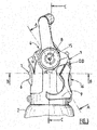
- the Figure 1 presents an embodiment of a rigid protective cover 1, commonly called a "cap”, arranged around a valve block 12 (not entirely visible), namely a valve with or without an integrated regulator, itself fixed to the neck of a gas cylinder 2, said protective cover 1 being provided with a carrying handle 5 according to the present invention.
- the gas cylinder 2 typically has a cylindrical steel body and a size between 10 and 150 cm, and a capacity of 0.5 to 20 liters (in water equivalent).
- the protective cover 1 makes it possible to protect the valve block against shocks, whether the valve block 12 is of the type with integrated regulator or RDI, or of the type without integrated regulator, typically a valve of the RDI type.
- the fixing around the valve block 12 on the neck of the gas bottle 2 is done by screwing.
- the protective cowling 1 comprises a cowling body forming a protective shell around an internal volume dimensioned to receive the valve block 12, and a carrying handle 5 designed to be taken in hand by a user.
- the carrying handle 5 is formed from a rigid material, such as a polymer or a metal or metal alloy, and is carried by one or more support posts 13 connecting mechanically the casing body to the carrying handle 5.
- the carrying handle 5 is generally arranged horizontally, that is to say perpendicular or almost perpendicular to the vertical axis of the bottle 2 and the casing 1.
- the carrying handle 5 has a slender shape, whether straight or curved, typically a length of less than 20 cm, typically from 6 to 15 cm.
- the support upright (s) 13 are fixed to one or both ends of the carrying handle 5 so as to allow a user to easily transport the cap / tap / bottle assembly by means of said carrying handle 5.
- the casing body 1 is typically made of a polymer and / or metal type material, preferably plastic material, such as PVC, PE, PET, PP, PMMA, PU, PA ...
- the support uprights 13 can be formed from a plastic material, such as the body of the cowling 1, but also from aluminum alloy or any other metallic material. They can be fixed to the handle 5 by screwing or welding, for example, or formed in one piece.
- the protective cowling 1 also has openings 11, 14 giving access to the valve block 12 located in the internal volume of the cowling body 1.
- a first opening 11 is arranged at the upper part 1a, also called the upper part, of the protective cover 1, within which is housed a pressure indicator device, such as a manometer 4, or with a needle, either electronic, or the contents of the bottle, such as a device indicating autonomy.
- the lower part 1b, also called the lower part, of the cowling 1 is located at the level of the bottle 2.
- the protective cowling 1 comprises a second opening 14 arranged in front of the protective cowling 1, within which is housed the rotary flywheel 6 controlling the flow of gas passing through the valve block 12.
- valve block 12 comprises a rotary flywheel 6, located on the front face, which can be manipulated by a user to control the gas flow, which rotary flywheel 6 is arranged around a gas outlet connector 7 for withdrawing the stored gas. in bottle 2.
- the axis AA of the pressure indicator device that is to say of the pressure gauge 4, the axis BB of the rotary flywheel 6 and the axis CC of the bottle 2 are coplanar.
- the axis AA of the pressure indicator device 4 and the axis BB of the rotary flywheel 6 form an angle ⁇ of between 0 ° and 90 °, preferably at least 30 °, for example between 45 ° and 85 ° , as illustrated in Figures 2 and 3 .
- the protective covering 1 comprises a flat surface 10 at its upper part 1a, that is to say at the top of the covering 1, within which the flat opening 10 is formed the first opening 11.
- planar surface 10 in fact constitutes an oblique face with respect to the axis of the bottle 2.
- the planar surface 10 is perpendicular to the axis AA of the pressure gauge 4, as shown schematically in Figure 3 .
- the pressure indicator device 4 is arranged in the first opening 11 arranged in the flat surface 10 so that its upper window is flush with the said flat surface 10, or is slightly recessed within of the housing formed by the first opening 11 relative to said planar surface 10 or alternatively either, slightly projecting outwardly relative to the planar surface 10.
- the pressure indicator device 4 can be fixed to the body of the valve block located in the internal volume of the cowling 1 or to the cowling.
- valve block 12 also includes a filling connection 16, (cf. Fig. 3 ) located on the rear face and accessible via a third opening (not visible in the Figures) arranged in the rear face of the cowling 1, which filling connection is used to introduce gas into the bottle 2 when the latter is empty or almost empty, as well as a pressurized gas outlet connector 8, arranged opposite the cover (see Fig. 3 ) within a fourth opening 15 made in the body of the cowling 1.
- the protective cowling 1 comprises, on the side of its rear face, a pivoting hooking device 9, between a fully folded position, called “rest” (shown schematically in Figure 3 ), that is to say the position adopted by the latching device 9 when it is stored and in contact or almost in contact with the casing body 1, and a fully unfolded position called “latching”, c 'is to say the position adopted by the hooking device 9 when it is completely extended and can be hung on a support, such as a bed bar or the like.
- the hooking device 9 pivots by a given angle around the pivot axis DD shown in Fig. 3
- a gas cylinder 2 equipped with a cover 1 with pressure or autonomy indicator device according to the invention is particularly suitable for use in a medical environment, in particular it is suitable for the storage of any medical gas or gas mixture, in particular of oxygen, air, N 2 O / O 2 , He / O 2 , NO / nitrogen or other type.
Landscapes
- Engineering & Computer Science (AREA)
- Mechanical Engineering (AREA)
- General Engineering & Computer Science (AREA)
- Filling Or Discharging Of Gas Storage Vessels (AREA)
Abstract
Description
- L'invention porte sur un ensemble de distribution de gaz, notamment de gaz médicaux, comprenant une bouteille de gaz, un bloc robinet fixé sur la bouteille de gaz et un capotage de protection agencé autour dudit bloc robinet, ledit bloc robinet comprenant un dispositif indicateur de pression, tel manomètre, ou un dispositif indicateur du contenu de la bouteille, tel un dispositif indicateur d'autonomie, venant se loger dans la partie supérieure du capotage de protection et préférentiellement un volant en façade du capotage.
- Les gaz industriels et médicaux sont couramment conditionnés dans des récipients de gaz, typiquement des bouteilles de gaz, équipés d'un bloc robinet, avec ou sans détendeur intégré, à savoir un robinet simple de type ouvert/fermé ou un robinet à détendeur intégré, encore appelé RDI, permettant de contrôler débit et pression du gaz délivré.
- Afin de protéger ce bloc robinet, il est courant d'agencer au niveau du col de la bouteille de gaz et autour dudit bloc robinet, un capotage de protection formant coque protectrice autour dudit bloc robinet. Un tel capotage est couramment appelé « chapeau ».
- Par ailleurs, pour permettre d'accrocher l'ensemble bouteille/chapeau/robinet à un support, tel un barreau de lit d'hôpital, un brancard, une tringle ou support d'accrochage d'un véhicule d'urgence, par exemple une unité de SAMU ou analogue, il est usuel d'aménager sur le chapeau, un système d'accrochage fixe ou mobile, notamment pivotant.
- Afin de faciliter le transport et les manipulations de l'ensemble bouteille/bloc robinet/capotage, il est usuel de doter le capotage d'une poignée de transport qui, en général, le surmonte et permet son portage manuel à une main par les utilisateurs.
- Des capotages de ce type sont décrits notamment par les documents
EP-A-629812 DE-A-10057469 ,US-A-2004/020793 etEP-A-2586481 . - Afin de contrôler la pression du gaz, il est courant de fixer un dispositif indicateur de pression, tel un manomètre sur un des passages de gaz traversant le bloc robinet.
- Or, le positionnement de ce dispositif indicateur de pression en partie basse du robinet, du fait de contraintes techniques, notamment du fait que le passage de gaz soumis à la pression de la bouteille est situé en partie basse du robinet, fait qu'il est souvent difficile ou peu aisé de lire la pression indiquée par le dispositif indicateur de pression et est souvent source d'erreurs de lecture.
- En outre, pour contrôler le débit du gaz délivré, c'est-à-dire autoriser ou interdire le cheminement du gaz dans le bloc robinet et donc une sortie de gaz dudit bloc, on agence souvent sur le bloc robinet, un volant rotatif agissant sur des organes de contrôle internes au bloc robinet.
- Or, là encore, du fait de l'utilisation d'un capotage de protection entourant le bloc robinet, il est souvent difficile ou peu aisé pour l'utilisateur de manœuvrer le volant rotatif.
- Au vu de cela, le problème qui se pose est d'améliorer le confort de lecture du dispositif indicateur de pression équipant un bloc robinet protégé par un capotage de protection pour bouteille de gaz en évitant les inconvénients susmentionnés, et préférentiellement de permettre par ailleurs une manœuvre aisée du volant rotatif contrôlant le débit de gaz.
- La solution de l'invention est un ensemble de distribution de gaz comprenant une bouteille de gaz, un bloc robinet fixé sur la bouteille de gaz et un capotage de protection agencé autour dudit bloc robinet, ledit bloc robinet comprenant un dispositif indicateur de pression, tel un manomètre, ou du contenu de la bouteille et un volant rotatif, manœuvrable par un opérateur, contrôlant le débit de gaz, caractérisé en ce que le capotage de protection comprend une première ouverture aménagée au niveau de la partie supérieure du capotage de protection et au sein de laquelle vient se loger le dispositif indicateur de pression ou du contenu de la bouteille.
- Selon le cas, l'ensemble de l'invention peut comprendre l'une ou plusieurs des caractéristiques techniques suivantes :
- le dispositif indicateur de pression est un manomètre.
- le dispositif indicateur du contenu de la bouteille est un indicateur d'autonomie en gaz.
- le dispositif indicateur du contenu de la bouteille est un dispositif à aiguille ou digital indiquant une estimation de la durée d'utilisation du gaz correspondant à la quantité de gaz résiduel dans la bouteille.
- le dispositif indicateur du contenu de la bouteille est de préférence un dispositif électronique qui calcule et affiche une autonomie en gaz exprimée en unité de temps.
- le dispositif indicateur de pression ou du contenu de la bouteille est fixé au bloc robinet de manière à permettre de mesurer la pression de gaz s'exerçant au sein d'un passage de gaz traversant ledit bloc robinet.
- le capotage de protection comprend une deuxième ouverture aménagée latéralement dans le capotage de protection et au sein de laquelle vient se loger le volant rotatif.
- l'axe (AA) du manomètre ou de l'indicateur de contenu, l'axe (BB) du volant rotatif et l'axe (CC) de la bouteille sont coplanaires.
- l'axe (AA) du manomètre ou de l'indicateur de contenu et l'axe (BB) du volant rotatif forment un angle α compris entre 0° et 90°, de préférence entre 30° et 85°.
- le capotage de protection comprend une surface plane au niveau sa partie supérieure, la première ouverture étant aménagée dans ladite surface plane.
- le dispositif indicateur de pression ou du contenu de la bouteille est agencé dans la première ouverture aménagée dans la surface plane de manière à affleurer au niveau de ladite surface plane
- alternativement, le dispositif indicateur de pression ou du contenu de la bouteille est agencé dans la première ouverture aménagée dans la surface plane de manière à être en retrait au sein du logement formé par la première ouverture par rapport à ladite surface plane, de préférence un retrait de 0,1 à 10 mm.
- alternativement encore, le dispositif indicateur de pression ou du contenu de la bouteille est agencé dans la première ouverture aménagée dans la surface plane de manière à faire saillie hors du logement formé par la première ouverture par rapport à ladite surface plane, de préférence en saillie de 0,1 à 10 mm.
- la surface plane forme une face oblique par rapport à l'axe de la bouteille.
- le bloc robinet est un robinet à détendeur intégré.
- le dispositif indicateur de pression est un manomètre à aiguille ou un manomètre électronique.
- le capotage est en matériau polymère, de préférence en plastique.
- le capotage de protection comprend en outre une poignée de portage reliée au capotage par l'intermédiaire d'un ou plusieurs montants-supports.
- la poignée de portage est agencée sur le capotage de manière à ce que le manomètre soit positionné entre la poignée de portage et le bloc robinet portant ledit manomètre.
- le bloc robinet comprend en outre un raccord de sortie de gaz et un raccord de remplissage.
- le volant rotatif est agencé sur la face avant du capotage.
- le capotage est en matériau polymère ou en métal ou alliage métallique, de préférence en plastique, tel que le PVC, le PE, le PET, le PP, le PMMA, le PU, le PA.... Il est à noter que le matériau plastique peut être chargé ou renforcé, c'est-à-dire additionné de fibres par exemple.
- la poignée de portage et/ou le ou les montants-supports sont formés d'un matériau rigide choisi parmi les polymères et les métaux ou alliages métalliques.
- la poignée de portage est globalement longiforme. Typiquement, sa longueur est comprise entre 5 et 20 cm, de préférence entre 6 et 15 cm.
- la poignée de portage surmonte le corps de capotage.
- la poignée de portage est horizontale ou quasi-horizontale et perpendiculaire à l'axe du capotage.
- la bouteille de gaz a une taille comprise entre 10 et 150 cm.
- la bouteille de gaz contient de 0,5 à 20 litres (contenance en équivalent eau).
- la bouteille de gaz a un corps cylindrique creux.
- la bouteille de gaz comprend un col portant un orifice de sortie du gaz au niveau duquel est fixé le bloc robinet.
- la bouteille de gaz contient un gaz ou mélange gazeux choisi parmi l'oxygène, l'air, un mélange N2O/O2, un mélange He/O2, un mélange NO/azote ou tout autre gaz ou mélange gazeux.
- la bouteille est en acier, en un alliage d'aluminium ou en matériau composite ou une combinaison de plusieurs de ces matériaux.
- la bouteille contient un gaz à une pression allant jusqu'à 350 bar environ.
- L'invention concerne en outre une utilisation d'un ensemble de distribution de gaz selon l'invention pour stocker ou distribuer un gaz ou mélange gazeux, de préférence un gaz ou mélange gazeux médical. De préférence, le gaz ou mélange gazeux est choisi parmi l'oxygène, air, N2O/O2, He/O2, NO/azote
- L'invention va maintenant être mieux comprise grâce à la description détaillée suivante, faite à titre illustratif mais non limitatif, en référence aux figures annexées parmi lesquelles :
- la
Figure 1 représente un mode de réalisation d'un ensemble bouteille/bloc robinet/capotage selon l'invention, - la
Figure 2 représente une vue de la façade avant du capotage de laFigure 1 et - la
Figure 3 représente une vue de côté du capotage de laFigure 1 . - La
Figure 1 présente un mode de réalisation d'un capotage de protection 1 rigide, couramment appelé « chapeau », agencé autour d'un bloc robinet 12 (non entièrement visible), à savoir un robinet avec ou sans détendeur intégré, lui-même fixé sur le col d'une bouteille de gaz 2, ledit capotage de protection 1 étant muni d'une poignée de transport 5 selon la présente invention. - La bouteille de gaz 2 a typiquement un corps cylindrique en acier et une taille entre 10 et 150 cm, et une contenance de 0,5 à 20 litres (en équivalent eau).
- Le capotage de protection 1 permet de protéger le bloc robinet contre les chocs, que le bloc robinet 12 soit du type avec détendeur intégré ou RDI, ou du type sans détendeur intégré, typiquement un robinet de type RDI. La fixation autour du bloc de robinet 12 sur le col de la bouteille de gaz 2 se fait par vissage.
- Plus précisément, le capotage de protection 1 comprend un corps de capotage formant une coque protectrice autour d'un volume interne dimensionné pour recevoir le bloc robinet 12, et une poignée de portage 5 conçue pour être prise en main par un utilisateur.
- La poignée de portage 5 est formée d'un matériau rigide, tel un polymère ou un métal ou alliage métallique, et est portée par un ou plusieurs montants-supports 13 reliant mécaniquement le corps de capotage à la poignée de portage 5. La poignée de portage 5 est généralement agencée horizontalement, c'est-à-dire perpendiculairement ou quasi-perpendiculairement par rapport à l'axe vertical de la bouteille 2 et du capotage 1. La poignée de portage 5 a une forme longiligne, qu'elle soit rectiligne ou incurvée, typiquement une longueur inférieure à 20 cm, typiquement de 6 à 15 cm.
- Le ou les montants-supports 13 sont fixés à l'une ou aux deux extrémités de la poignée de portage 5 de manière à permettre à un utilisateur de transporter facilement l'ensemble chapeau/robinet/bouteille au moyen de ladite poignée de portage 5.
- Le corps du capotage 1 est typiquement en un matériau de type polymère et/ou métal, préférentiellement en matériau plastique, tel que PVC, PE, PET, PP, PMMA, PU, PA...
- De même, les montants-supports 13 peuvent être formés d'un matériau plastique, comme le corps du capotage 1, mais aussi en alliage d'aluminium ou tout autre matériau métallique. Ils peuvent être fixés à la poignée 5 par vissage ou soudage, par exemple, ou formés d'une seule pièce.
- Le capotage de protection 1 présente par ailleurs des ouvertures 11, 14 donnant accès au bloc robinet 12 situé dans le volume interne du corps de capotage 1.
- Plus précisément, une première ouverture 11 est aménagée au niveau de la partie supérieure la, encore appelée partie haute, du capotage de protection 1, au sein de laquelle vient se loger un dispositif indicateur de pression, tel un manomètre 4, soit à aiguille, soit électronique, ou du contenu de la bouteille, tel un dispositif indicateur d'autonomie. La partie inférieure 1b, encore appelée partie basse, du capotage 1 est située au niveau de la bouteille 2.
- A des fins de simplification, dans le reste de la description, on parlera de dispositif indicateur de pression mais les explications données s'appliquant stricto sensu à un dispositif indicateur du contenu de la bouteille, tel un dispositif indicateur d'autonomie, qui se substituerait au dispositif indicateur de pression.
- Par ailleurs, le capotage de protection 1 comprend une deuxième ouverture 14 aménagée en façade du capotage de protection 1, au sein de laquelle vient se loger le volant rotatif 6 contrôlant le débit du gaz traversant le bloc robinet 12.
- Plus précisément, le bloc robinet 12 comprend un volant rotatif 6, situé en face avant, manipulable par un utilisateur pour contrôler le débit de gaz, lequel volant rotatif 6 est agencé autour d'un raccord de sortie de gaz 7 pour soutirer le gaz stocké dans la bouteille 2.
- De préférence, l'axe AA du dispositif indicateur de pression, c'est-à-dire du manomètre 4, l'axe BB du volant rotatif 6 et l'axe CC de la bouteille 2 sont coplanaires. Avantageusement, l'axe AA du dispositif indicateur de pression 4 et l'axe BB du volant rotatif 6 forment un angle α compris entre 0° et 90°, de préférence d'au moins 30°, par exemple entre 45° et 85°, comme illustré en
Figures 2 et3 . - Selon le mode de réalisation schématisé en
Figures 1 à 3 , le capotage de protection 1 comprend une surface plane 10 au niveau sa partie supérieure la, c'est-à-dire en haut de capotage 1, au sein de laquelle surface plane 10 est aménagée la première ouverture 11. - La surface plane 10 constitue en fait une face oblique par rapport à l'axe de la bouteille 2. De préférence, la surface plane 10 est perpendiculaire à l'axe AA du manomètre 4, comme schématisé en
Figure 3 . - Selon le mode de réalisation considéré, le dispositif indicateur de pression 4 est agencé dans la première ouverture 11 aménagée dans la surface plane 10 de manière à ce que sa vitre supérieure affleure au niveau de ladite surface plane 10, ou soit légèrement en retrait au sein du logement formé par la première ouverture 11 par rapport à ladite surface plane 10 ou encore soit, à l'inverse, légèrement en saillie vers l'extérieur par rapport à la surface plane 10.
- Le dispositif indicateur de pression 4 peut être fixé au corps du bloc robinet situé dans le volume interne du capotage 1 ou au capotage.
- Un tel agencement du dispositif indicateur de pression 4, c'est-à-dire du manomètre, en position haute et en façade du capotage 1, avec de préférence sa vitre de lecture inclinée de manière à former un angle donné par rapport à l'axe CC de la bouteille 2, permet de faciliter considérablement à l'utilisateur la lecture de pression délivrée par le dispositif indicateur de pression ou manomètre 4 qu'il soit à aiguille ou électronique.
- En outre, le fait de placer le volant rotatif manœuvrable par l'utilisateur en façade 1c du capotage 1, permet une manœuvre aisée du volant rotatif contrôlant le débit de gaz.
- Par ailleurs, le bloc robinet 12 comprend également un raccord de remplissage 16, (cf.
Fig. 3 ) situé en face arrière et accessible via une troisième ouverture (non visible sur les Figures) aménagée dans la face arrière du capotage 1, lequel raccord de remplissage sert à introduire du gaz dans la bouteille 2 lorsque celle-ci est vide ou presque vide, ainsi qu'un raccord de sortie de gaz sous pression 8, agencé en face latérale du capotage (voirFig. 3 ) au sein d'une quatrième ouverture 15 pratiquée dans le corps du capotage 1. - Afin de permettre l'accroche ou l'arrimage de l'ensemble bouteille/bloc robinet/capotage à un support, tel un barreau de lit d'hôpital ou de brancard, le capotage de protection 1 comprend, du côté de sa face arrière, un dispositif d'accrochage 9 pivotant, entre une position totalement repliée, dite « de repos » (schématisé en
Figure 3 ), c'est-à-dire la position adoptée par le dispositif d'accrochage 9 lorsqu'il est rangé et en contact ou quasi-contact du corps du capotage 1, et une position totalement dépliée dite « d'accrochage », c'est-à-dire la position adoptée par le dispositif d'accrochage 9 lorsqu'il est complètement sorti et peut être accroché à un support, tel un barreau de lit ou analogue. Le dispositif d'accrochage 9 pivote d'un angle donné autour de l'axe DD de pivotement montré enFig. 3 - Une bouteille de gaz 2 équipée d'un capotage 1 avec dispositif indicateur de pression ou d'autonomie selon l'invention est particulièrement adaptée pour un usage en milieu médical, en particulier elle convient au stockage de tout gaz ou mélange gazeux médical, en particulier de type oxygène, air, N2O/O2, He/O2, NO/azote ou autre.
Claims (15)
- Ensemble de distribution de gaz comprenant une bouteille de gaz (2), un bloc robinet (12) fixé sur la bouteille de gaz (2) et un capotage de protection (1) agencé autour dudit bloc robinet (12), ledit bloc robinet (12) comprenant un dispositif indicateur de pression ou de contenu (4) et un volant rotatif (6), manœuvrable par un opérateur, contrôlant le débit de gaz, le capotage de protection (1) comprenant une première ouverture (11) aménagée au niveau de la partie supérieure (la) du capotage de protection (1) et au sein de laquelle vient se loger le dispositif indicateur de pression ou du contenu de la bouteille (4), caractérisé en ce que l'axe (AA) du manomètre ou du dispositif indicateur du contenu de la bouteille et l'axe (BB) du volant rotatif (6) forment un angle (a) compris entre 0° et 90°.
- Ensemble selon la revendication 1, caractérisé en ce que le capotage de protection (1) comprend une deuxième ouverture (14) aménagée latéralement dans le capotage de protection (1) et au sein de laquelle vient se loger le volant rotatif (6).
- Ensemble selon la revendication 1, caractérisé en ce que l'axe (AA) du dispositif indicateur de pression (4) ou du contenu de la bouteille, l'axe (BB) du volant rotatif (6) et l'axe (CC) de la bouteille (2) sont coplanaires.
- Ensemble selon la revendication 1, caractérisé en ce que l'axe (AA) du manomètre ou du dispositif indicateur du contenu de la bouteille et l'axe (BB) du volant rotatif (6) forment un angle (a) compris entre 30° et 85°, de préférence entre 45° et 85°.
- Ensemble selon la revendication 1, caractérisé en ce que le capotage de protection (1) comprend une surface plane (10) au niveau sa partie supérieure (la), la première ouverture (11) étant aménagée dans ladite surface plane (10).
- Ensemble selon la revendication 1, caractérisé en ce que le capotage de protection (1) comprend en outre un dispositif d'accrochage (9) et une poignée de portage (5) reliée au capotage (1) par l'intermédiaire d'un ou plusieurs montants-supports (13).
- Ensemble selon l'une des revendications 1 ou 6, caractérisé en ce que le capotage de protection (1) comprend un dispositif d'accrochage (9) pivotant.
- Ensemble selon la revendication 1, caractérisé en ce que le bloc robinet (12) est un robinet à détendeur intégré.
- Ensemble selon la revendication 1, caractérisé en ce que le dispositif indicateur de pression (4) est un manomètre à aiguille ou un manomètre électronique ou le dispositif indicateur du contenu de la bouteille est un dispositif indicateur d'autonomie.
- Ensemble selon la revendication 1, caractérisé en ce que le capotage (1) est en matériau polymère, de préférence en plastique.
- Ensemble selon la revendication 6, caractérisé en ce que la poignée de portage (5) est agencée sur le capotage (1) de manière à ce que le dispositif indicateur de pression (4) ou d'autonomie soit positionné entre la poignée de portage (5) et le bloc robinet (12) portant ledit dispositif indicateur de pression (4).
- Ensemble selon la revendication 1, caractérisé en ce que le volant rotatif (6) est agencé sur la face avant (1c) du capotage (1).
- Ensemble selon l'une des revendications 1, 2 ou 12, caractérisé en ce que le volant rotatif (6) est agencé coaxialement autour du raccord de sortie de gaz (7), au sein de la deuxième ouverture (14).
- Utilisation d'un ensemble selon l'une des revendications précédentes pour stocker ou distribuer un gaz ou mélange gazeux.
- Utilisation selon la revendication 14 dans laquelle le gaz ou mélange gazeux est choisi parmi l'oxygène, air, N2O/O2, He/O2 et NO/azote.
Applications Claiming Priority (4)
| Application Number | Priority Date | Filing Date | Title |
|---|---|---|---|
| FR1358766 | 2013-09-12 | ||
| FR1358872A FR3010767B1 (fr) | 2013-09-16 | 2013-09-16 | Systeme d'accrochage de bouteille de gaz medical |
| EP14713556.0A EP3044495B1 (fr) | 2013-09-12 | 2014-03-12 | Ensemble comprenant un capotage de protection et une bouteille de gaz avec un dispositif indicateur de pression ou d'autonomie en position haute |
| PCT/FR2014/050558 WO2015036663A1 (fr) | 2013-09-12 | 2014-03-12 | Ensemble comprenant un capotage de protection et une bouteille de gaz avec un dispositif indicateur de pression ou d'autonomie en position haute |
Related Parent Applications (2)
| Application Number | Title | Priority Date | Filing Date |
|---|---|---|---|
| EP14713556.0A Division-Into EP3044495B1 (fr) | 2013-09-12 | 2014-03-12 | Ensemble comprenant un capotage de protection et une bouteille de gaz avec un dispositif indicateur de pression ou d'autonomie en position haute |
| EP14713556.0A Division EP3044495B1 (fr) | 2013-09-12 | 2014-03-12 | Ensemble comprenant un capotage de protection et une bouteille de gaz avec un dispositif indicateur de pression ou d'autonomie en position haute |
Publications (2)
| Publication Number | Publication Date |
|---|---|
| EP3643958A1 true EP3643958A1 (fr) | 2020-04-29 |
| EP3643958B1 EP3643958B1 (fr) | 2022-10-12 |
Family
ID=50390123
Family Applications (2)
| Application Number | Title | Priority Date | Filing Date |
|---|---|---|---|
| EP14713556.0A Active EP3044495B1 (fr) | 2013-09-12 | 2014-03-12 | Ensemble comprenant un capotage de protection et une bouteille de gaz avec un dispositif indicateur de pression ou d'autonomie en position haute |
| EP19208588.4A Active EP3643958B1 (fr) | 2013-09-12 | 2014-03-12 | Ensemble comprenant un capotage de protection et une bouteille de gaz avec un dispositif indicateur de pression ou d'autonomie en position haute |
Family Applications Before (1)
| Application Number | Title | Priority Date | Filing Date |
|---|---|---|---|
| EP14713556.0A Active EP3044495B1 (fr) | 2013-09-12 | 2014-03-12 | Ensemble comprenant un capotage de protection et une bouteille de gaz avec un dispositif indicateur de pression ou d'autonomie en position haute |
Country Status (8)
| Country | Link |
|---|---|
| US (1) | US20160223141A1 (fr) |
| EP (2) | EP3044495B1 (fr) |
| CN (1) | CN105518374A (fr) |
| AU (1) | AU2014320235B2 (fr) |
| CA (1) | CA2922756A1 (fr) |
| ES (1) | ES2816330T3 (fr) |
| PT (1) | PT3044495T (fr) |
| WO (1) | WO2015036663A1 (fr) |
Cited By (1)
| Publication number | Priority date | Publication date | Assignee | Title |
|---|---|---|---|---|
| FR3133320A1 (fr) | 2022-03-10 | 2023-09-15 | L'air Liquide Societe Anonyme Pour L'etude Et L'exploitation Des Procedes Georges Claude | Robinet pour récipient de gaz à détendeur intégré amélioré |
Families Citing this family (8)
| Publication number | Priority date | Publication date | Assignee | Title |
|---|---|---|---|---|
| LU92388B1 (en) | 2014-03-03 | 2015-09-04 | Luxembourg Patent Co Sa | Cover for gas cylinder tap |
| FR3018584B1 (fr) | 2014-03-12 | 2016-04-15 | Air Liquide | Capotage de protection avec systeme d’accrochage pivotant pour bouteille de gaz |
| LU92873B1 (en) * | 2015-11-16 | 2017-06-08 | Luxembourg Patent Co | Cover for gas cylinder tap with removable front area |
| LU92953B1 (en) | 2016-01-21 | 2017-09-25 | Luxembourg Patent Co | Calculation of remaining usage time of a gas cylinder |
| USD1008410S1 (en) * | 2021-07-29 | 2023-12-19 | Grand Mate Co., Ltd. | Gas tank |
| USD1000246S1 (en) * | 2022-02-23 | 2023-10-03 | Amtrol Licensing, Inc. | Handle assembly for a gas cylinder |
| USD1098358S1 (en) * | 2023-06-12 | 2025-10-14 | Ghotra Innovations Inc. | Hydrogen gas cylinder assembly |
| USD1121536S1 (en) | 2023-06-12 | 2026-04-07 | Ghotra Innovations Inc. | Portable power station |
Citations (9)
| Publication number | Priority date | Publication date | Assignee | Title |
|---|---|---|---|---|
| EP0629812A1 (fr) | 1993-06-03 | 1994-12-21 | Compagnie Francaise De Produits Oxygenes | Chapeau de bouteille de gaz |
| WO2002040914A2 (fr) * | 2000-11-17 | 2002-05-23 | Controlink, Llc. | Robinet a poignee intelligente |
| DE10057469A1 (de) | 2000-11-20 | 2002-05-29 | Messer Griesheim Gmbh | Schutzkappe für Druckgasflaschen mit Halteschiene |
| US20040020793A1 (en) | 2000-04-17 | 2004-02-05 | Luc Peterolff | Gas bottle with protective casing for use in the medical field |
| EP1512895A1 (fr) * | 2003-09-03 | 2005-03-09 | Taema | Robinet-détendeur intégré avec moyens de blocage de l'organe d'actionnement |
| WO2008149312A1 (fr) * | 2007-06-05 | 2008-12-11 | L'air Liquide-Societe Anonyme Pour L'etude Et L'exploitation Des Procedes Georges Claude | Dispositif de commande de gaz à couvercle de protection |
| EP2116332A1 (fr) * | 2008-05-05 | 2009-11-11 | Fever Industrial Co. Ltd. | Dispositif portable pour alimenter un outil pneumatique en CO2 sous pression à partir d'un récipient pressurisé |
| EP2339222A2 (fr) * | 2009-12-21 | 2011-06-29 | Linde Aktiengesellschaft | Récipient sous pression avec capteur de pression |
| EP2586481A1 (fr) | 2011-10-27 | 2013-05-01 | Linde Aktiengesellschaft | Couvercle pour bouchon de valve d'un cylindre de gaz |
Family Cites Families (11)
| Publication number | Priority date | Publication date | Assignee | Title |
|---|---|---|---|---|
| US5119844A (en) * | 1991-11-12 | 1992-06-09 | Cannon Reuben C | Air tank conversion kit |
| FR2735209B1 (fr) * | 1995-06-08 | 1997-07-25 | Air Liquide | Ensemble robinet/detendeur pour bouteille de gaz et bouteille de gaz equipee d'un tel ensemble |
| FR2791757B1 (fr) * | 1999-04-01 | 2001-06-15 | Air Liquide | Chapeau ouvert composite de grandes bouteilles de gaz industriels et medicaux |
| FR2828922B1 (fr) * | 2001-08-23 | 2004-06-11 | Air Liquide | Robinet de controle du debit d'un fluide equipe d'un levier a plusieurs positions stables |
| US6886587B2 (en) * | 2002-11-04 | 2005-05-03 | Paragon Holdings, Llc | Housing for gas regulator and gauges |
| CN1946458A (zh) * | 2004-03-04 | 2007-04-11 | 阿沃克斯系统股份有限公司 | 具有可选输出流率的呼吸气体分配器 |
| FR2875891B1 (fr) * | 2004-09-29 | 2008-06-13 | Air Liquide Sante Int | Bouteille de gaz medical avec coque protectrice peripherique |
| KR20070085624A (ko) * | 2004-12-03 | 2007-08-27 | 프랙스에어 테크놀로지, 인코포레이티드 | 인체공학적인 슈라우드 |
| US7373947B2 (en) * | 2005-03-03 | 2008-05-20 | Irwin Industrial Tool Company | Storage system and protective device for tanks |
| GB0522048D0 (en) * | 2005-10-28 | 2005-12-07 | Boc Group Plc | Valve guard assembly |
| US20090272443A1 (en) * | 2008-05-02 | 2009-11-05 | Chi Ping Lee | Portable device for supplying compressed CO2 from a pressure vessel to a pneumatic tool |
-
2014
- 2014-03-12 CA CA2922756A patent/CA2922756A1/fr not_active Abandoned
- 2014-03-12 ES ES14713556T patent/ES2816330T3/es active Active
- 2014-03-12 AU AU2014320235A patent/AU2014320235B2/en not_active Expired - Fee Related
- 2014-03-12 PT PT147135560T patent/PT3044495T/pt unknown
- 2014-03-12 EP EP14713556.0A patent/EP3044495B1/fr active Active
- 2014-03-12 US US15/021,506 patent/US20160223141A1/en not_active Abandoned
- 2014-03-12 EP EP19208588.4A patent/EP3643958B1/fr active Active
- 2014-03-12 WO PCT/FR2014/050558 patent/WO2015036663A1/fr not_active Ceased
- 2014-03-12 CN CN201480049211.2A patent/CN105518374A/zh active Pending
Patent Citations (9)
| Publication number | Priority date | Publication date | Assignee | Title |
|---|---|---|---|---|
| EP0629812A1 (fr) | 1993-06-03 | 1994-12-21 | Compagnie Francaise De Produits Oxygenes | Chapeau de bouteille de gaz |
| US20040020793A1 (en) | 2000-04-17 | 2004-02-05 | Luc Peterolff | Gas bottle with protective casing for use in the medical field |
| WO2002040914A2 (fr) * | 2000-11-17 | 2002-05-23 | Controlink, Llc. | Robinet a poignee intelligente |
| DE10057469A1 (de) | 2000-11-20 | 2002-05-29 | Messer Griesheim Gmbh | Schutzkappe für Druckgasflaschen mit Halteschiene |
| EP1512895A1 (fr) * | 2003-09-03 | 2005-03-09 | Taema | Robinet-détendeur intégré avec moyens de blocage de l'organe d'actionnement |
| WO2008149312A1 (fr) * | 2007-06-05 | 2008-12-11 | L'air Liquide-Societe Anonyme Pour L'etude Et L'exploitation Des Procedes Georges Claude | Dispositif de commande de gaz à couvercle de protection |
| EP2116332A1 (fr) * | 2008-05-05 | 2009-11-11 | Fever Industrial Co. Ltd. | Dispositif portable pour alimenter un outil pneumatique en CO2 sous pression à partir d'un récipient pressurisé |
| EP2339222A2 (fr) * | 2009-12-21 | 2011-06-29 | Linde Aktiengesellschaft | Récipient sous pression avec capteur de pression |
| EP2586481A1 (fr) | 2011-10-27 | 2013-05-01 | Linde Aktiengesellschaft | Couvercle pour bouchon de valve d'un cylindre de gaz |
Cited By (2)
| Publication number | Priority date | Publication date | Assignee | Title |
|---|---|---|---|---|
| FR3133320A1 (fr) | 2022-03-10 | 2023-09-15 | L'air Liquide Societe Anonyme Pour L'etude Et L'exploitation Des Procedes Georges Claude | Robinet pour récipient de gaz à détendeur intégré amélioré |
| EP4257868A1 (fr) | 2022-03-10 | 2023-10-11 | L'air Liquide, Societe Anonyme Pour L'etude Et L'exploitation Des Procedes Georges Claude | Robinet pour récipient de gaz à détendeur intégré amélioré |
Also Published As
| Publication number | Publication date |
|---|---|
| CN105518374A (zh) | 2016-04-20 |
| ES2816330T3 (es) | 2021-04-05 |
| EP3044495B1 (fr) | 2020-08-19 |
| EP3044495A1 (fr) | 2016-07-20 |
| WO2015036663A1 (fr) | 2015-03-19 |
| US20160223141A1 (en) | 2016-08-04 |
| AU2014320235A1 (en) | 2016-04-21 |
| AU2014320235B2 (en) | 2018-10-04 |
| PT3044495T (pt) | 2020-09-21 |
| EP3643958B1 (fr) | 2022-10-12 |
| CA2922756A1 (fr) | 2015-03-19 |
Similar Documents
| Publication | Publication Date | Title |
|---|---|---|
| EP3044495B1 (fr) | Ensemble comprenant un capotage de protection et une bouteille de gaz avec un dispositif indicateur de pression ou d'autonomie en position haute | |
| EP2918892B1 (fr) | Capotage de protection pour bouteille de gaz avec écran d'affichage électronique en position haute | |
| EP3480509B1 (fr) | Utilisation d'une bouteille de gaz avec capotage de protection avec système d'accrochage pivotant | |
| EP3117136B1 (fr) | Bloc robinet pour récipient de gaz avec dispositif indicateur de pression ou d'autonomie en position haute | |
| EP3002498B1 (fr) | Récipient de gaz avec bloc robinet équipé d'un écran tactile d'affichage d'informations | |
| EP2918891B1 (fr) | Capotage avec rebord de protection de l'organe de commande rotatif d'un bloc robinet de récipient de gaz | |
| EP3260760B1 (fr) | Capotage de protection avec système d'accrochage pivotant à butée d'arrêt pour récipient de gaz | |
| EP3531006B1 (fr) | Capotage de protection à système d'accrochage pivotant pour récipient de gaz | |
| EP2937620B1 (fr) | Capotage de protection pour bouteille de gaz | |
| FR3042584A1 (fr) | Bloc rdi de distribution de gaz avec dispositif indicateur agence au centre du volant de manœuvre | |
| EP3267092A1 (fr) | Ensemble de distribution de gaz comprenant un capotage agencé autour d'un bloc robinet équipant un récipient de gaz | |
| FR3052845A1 (fr) | Capotage de protection de recipient de gaz a ouverture recouverte par paroi amovible | |
| FR3018585A1 (fr) | Capotage de protection avec poignee de portable a confort ameliore | |
| FR3052848A1 (fr) | Capotage de protection en plusieurs parties pour bouteille de gaz | |
| FR3018582A1 (fr) | Capotage de protection avec systeme d’accrochage antiderapant pour recipient de gaz | |
| FR3067788A1 (fr) | Capotage pour recipient de gaz portant un organe de commande de la vanne d'isolation d'un robinet a detendeur integre |
Legal Events
| Date | Code | Title | Description |
|---|---|---|---|
| PUAI | Public reference made under article 153(3) epc to a published international application that has entered the european phase |
Free format text: ORIGINAL CODE: 0009012 |
|
| STAA | Information on the status of an ep patent application or granted ep patent |
Free format text: STATUS: THE APPLICATION HAS BEEN PUBLISHED |
|
| AC | Divisional application: reference to earlier application |
Ref document number: 3044495 Country of ref document: EP Kind code of ref document: P |
|
| AK | Designated contracting states |
Kind code of ref document: A1 Designated state(s): AL AT BE BG CH CY CZ DE DK EE ES FI FR GB GR HR HU IE IS IT LI LT LU LV MC MK MT NL NO PL PT RO RS SE SI SK SM TR |
|
| RIN1 | Information on inventor provided before grant (corrected) |
Inventor name: BAUNE, EMMANUEL Inventor name: TARANTELLO, CHIARA Inventor name: GERMANI, DAMIEN Inventor name: LIGONESCHE, RENAUD Inventor name: RUDNIANYN, PHILIPPE |
|
| STAA | Information on the status of an ep patent application or granted ep patent |
Free format text: STATUS: REQUEST FOR EXAMINATION WAS MADE |
|
| 17P | Request for examination filed |
Effective date: 20201029 |
|
| RBV | Designated contracting states (corrected) |
Designated state(s): AL AT BE BG CH CY CZ DE DK EE ES FI FR GB GR HR HU IE IS IT LI LT LU LV MC MK MT NL NO PL PT RO RS SE SI SK SM TR |
|
| GRAP | Despatch of communication of intention to grant a patent |
Free format text: ORIGINAL CODE: EPIDOSNIGR1 |
|
| STAA | Information on the status of an ep patent application or granted ep patent |
Free format text: STATUS: GRANT OF PATENT IS INTENDED |
|
| INTG | Intention to grant announced |
Effective date: 20220609 |
|
| GRAS | Grant fee paid |
Free format text: ORIGINAL CODE: EPIDOSNIGR3 |
|
| GRAA | (expected) grant |
Free format text: ORIGINAL CODE: 0009210 |
|
| STAA | Information on the status of an ep patent application or granted ep patent |
Free format text: STATUS: THE PATENT HAS BEEN GRANTED |
|
| AC | Divisional application: reference to earlier application |
Ref document number: 3044495 Country of ref document: EP Kind code of ref document: P |
|
| AK | Designated contracting states |
Kind code of ref document: B1 Designated state(s): AL AT BE BG CH CY CZ DE DK EE ES FI FR GB GR HR HU IE IS IT LI LT LU LV MC MK MT NL NO PL PT RO RS SE SI SK SM TR |
|
| REG | Reference to a national code |
Ref country code: GB Ref legal event code: FG4D Free format text: NOT ENGLISH |
|
| REG | Reference to a national code |
Ref country code: CH Ref legal event code: EP |
|
| REG | Reference to a national code |
Ref country code: DE Ref legal event code: R096 Ref document number: 602014085233 Country of ref document: DE |
|
| REG | Reference to a national code |
Ref country code: IE Ref legal event code: FG4D Free format text: LANGUAGE OF EP DOCUMENT: FRENCH |
|
| REG | Reference to a national code |
Ref country code: AT Ref legal event code: REF Ref document number: 1524373 Country of ref document: AT Kind code of ref document: T Effective date: 20221115 |
|
| REG | Reference to a national code |
Ref country code: LT Ref legal event code: MG9D |
|
| REG | Reference to a national code |
Ref country code: NL Ref legal event code: MP Effective date: 20221012 |
|
| REG | Reference to a national code |
Ref country code: AT Ref legal event code: MK05 Ref document number: 1524373 Country of ref document: AT Kind code of ref document: T Effective date: 20221012 |
|
| PG25 | Lapsed in a contracting state [announced via postgrant information from national office to epo] |
Ref country code: NL Free format text: LAPSE BECAUSE OF FAILURE TO SUBMIT A TRANSLATION OF THE DESCRIPTION OR TO PAY THE FEE WITHIN THE PRESCRIBED TIME-LIMIT Effective date: 20221012 |
|
| PG25 | Lapsed in a contracting state [announced via postgrant information from national office to epo] |
Ref country code: SE Free format text: LAPSE BECAUSE OF FAILURE TO SUBMIT A TRANSLATION OF THE DESCRIPTION OR TO PAY THE FEE WITHIN THE PRESCRIBED TIME-LIMIT Effective date: 20221012 Ref country code: PT Free format text: LAPSE BECAUSE OF FAILURE TO SUBMIT A TRANSLATION OF THE DESCRIPTION OR TO PAY THE FEE WITHIN THE PRESCRIBED TIME-LIMIT Effective date: 20230213 Ref country code: NO Free format text: LAPSE BECAUSE OF FAILURE TO SUBMIT A TRANSLATION OF THE DESCRIPTION OR TO PAY THE FEE WITHIN THE PRESCRIBED TIME-LIMIT Effective date: 20230112 Ref country code: LT Free format text: LAPSE BECAUSE OF FAILURE TO SUBMIT A TRANSLATION OF THE DESCRIPTION OR TO PAY THE FEE WITHIN THE PRESCRIBED TIME-LIMIT Effective date: 20221012 Ref country code: FI Free format text: LAPSE BECAUSE OF FAILURE TO SUBMIT A TRANSLATION OF THE DESCRIPTION OR TO PAY THE FEE WITHIN THE PRESCRIBED TIME-LIMIT Effective date: 20221012 Ref country code: ES Free format text: LAPSE BECAUSE OF FAILURE TO SUBMIT A TRANSLATION OF THE DESCRIPTION OR TO PAY THE FEE WITHIN THE PRESCRIBED TIME-LIMIT Effective date: 20221012 Ref country code: AT Free format text: LAPSE BECAUSE OF FAILURE TO SUBMIT A TRANSLATION OF THE DESCRIPTION OR TO PAY THE FEE WITHIN THE PRESCRIBED TIME-LIMIT Effective date: 20221012 |
|
| PG25 | Lapsed in a contracting state [announced via postgrant information from national office to epo] |
Ref country code: RS Free format text: LAPSE BECAUSE OF FAILURE TO SUBMIT A TRANSLATION OF THE DESCRIPTION OR TO PAY THE FEE WITHIN THE PRESCRIBED TIME-LIMIT Effective date: 20221012 Ref country code: PL Free format text: LAPSE BECAUSE OF FAILURE TO SUBMIT A TRANSLATION OF THE DESCRIPTION OR TO PAY THE FEE WITHIN THE PRESCRIBED TIME-LIMIT Effective date: 20221012 Ref country code: LV Free format text: LAPSE BECAUSE OF FAILURE TO SUBMIT A TRANSLATION OF THE DESCRIPTION OR TO PAY THE FEE WITHIN THE PRESCRIBED TIME-LIMIT Effective date: 20221012 Ref country code: IS Free format text: LAPSE BECAUSE OF FAILURE TO SUBMIT A TRANSLATION OF THE DESCRIPTION OR TO PAY THE FEE WITHIN THE PRESCRIBED TIME-LIMIT Effective date: 20230212 Ref country code: HR Free format text: LAPSE BECAUSE OF FAILURE TO SUBMIT A TRANSLATION OF THE DESCRIPTION OR TO PAY THE FEE WITHIN THE PRESCRIBED TIME-LIMIT Effective date: 20221012 Ref country code: GR Free format text: LAPSE BECAUSE OF FAILURE TO SUBMIT A TRANSLATION OF THE DESCRIPTION OR TO PAY THE FEE WITHIN THE PRESCRIBED TIME-LIMIT Effective date: 20230113 |
|
| REG | Reference to a national code |
Ref country code: DE Ref legal event code: R097 Ref document number: 602014085233 Country of ref document: DE |
|
| PG25 | Lapsed in a contracting state [announced via postgrant information from national office to epo] |
Ref country code: SM Free format text: LAPSE BECAUSE OF FAILURE TO SUBMIT A TRANSLATION OF THE DESCRIPTION OR TO PAY THE FEE WITHIN THE PRESCRIBED TIME-LIMIT Effective date: 20221012 Ref country code: RO Free format text: LAPSE BECAUSE OF FAILURE TO SUBMIT A TRANSLATION OF THE DESCRIPTION OR TO PAY THE FEE WITHIN THE PRESCRIBED TIME-LIMIT Effective date: 20221012 Ref country code: EE Free format text: LAPSE BECAUSE OF FAILURE TO SUBMIT A TRANSLATION OF THE DESCRIPTION OR TO PAY THE FEE WITHIN THE PRESCRIBED TIME-LIMIT Effective date: 20221012 Ref country code: DK Free format text: LAPSE BECAUSE OF FAILURE TO SUBMIT A TRANSLATION OF THE DESCRIPTION OR TO PAY THE FEE WITHIN THE PRESCRIBED TIME-LIMIT Effective date: 20221012 Ref country code: CZ Free format text: LAPSE BECAUSE OF FAILURE TO SUBMIT A TRANSLATION OF THE DESCRIPTION OR TO PAY THE FEE WITHIN THE PRESCRIBED TIME-LIMIT Effective date: 20221012 |
|
| PLBE | No opposition filed within time limit |
Free format text: ORIGINAL CODE: 0009261 |
|
| STAA | Information on the status of an ep patent application or granted ep patent |
Free format text: STATUS: NO OPPOSITION FILED WITHIN TIME LIMIT |
|
| PG25 | Lapsed in a contracting state [announced via postgrant information from national office to epo] |
Ref country code: SK Free format text: LAPSE BECAUSE OF FAILURE TO SUBMIT A TRANSLATION OF THE DESCRIPTION OR TO PAY THE FEE WITHIN THE PRESCRIBED TIME-LIMIT Effective date: 20221012 Ref country code: AL Free format text: LAPSE BECAUSE OF FAILURE TO SUBMIT A TRANSLATION OF THE DESCRIPTION OR TO PAY THE FEE WITHIN THE PRESCRIBED TIME-LIMIT Effective date: 20221012 |
|
| 26N | No opposition filed |
Effective date: 20230713 |
|
| REG | Reference to a national code |
Ref country code: DE Ref legal event code: R119 Ref document number: 602014085233 Country of ref document: DE |
|
| PG25 | Lapsed in a contracting state [announced via postgrant information from national office to epo] |
Ref country code: MC Free format text: LAPSE BECAUSE OF FAILURE TO SUBMIT A TRANSLATION OF THE DESCRIPTION OR TO PAY THE FEE WITHIN THE PRESCRIBED TIME-LIMIT Effective date: 20221012 |
|
| REG | Reference to a national code |
Ref country code: CH Ref legal event code: PL |
|
| GBPC | Gb: european patent ceased through non-payment of renewal fee |
Effective date: 20230312 |
|
| PG25 | Lapsed in a contracting state [announced via postgrant information from national office to epo] |
Ref country code: SI Free format text: LAPSE BECAUSE OF FAILURE TO SUBMIT A TRANSLATION OF THE DESCRIPTION OR TO PAY THE FEE WITHIN THE PRESCRIBED TIME-LIMIT Effective date: 20221012 |
|
| REG | Reference to a national code |
Ref country code: BE Ref legal event code: MM Effective date: 20230331 |
|
| PG25 | Lapsed in a contracting state [announced via postgrant information from national office to epo] |
Ref country code: LU Free format text: LAPSE BECAUSE OF NON-PAYMENT OF DUE FEES Effective date: 20230312 |
|
| REG | Reference to a national code |
Ref country code: IE Ref legal event code: MM4A |
|
| PG25 | Lapsed in a contracting state [announced via postgrant information from national office to epo] |
Ref country code: GB Free format text: LAPSE BECAUSE OF NON-PAYMENT OF DUE FEES Effective date: 20230312 |
|
| PG25 | Lapsed in a contracting state [announced via postgrant information from national office to epo] |
Ref country code: LI Free format text: LAPSE BECAUSE OF NON-PAYMENT OF DUE FEES Effective date: 20230331 Ref country code: IE Free format text: LAPSE BECAUSE OF NON-PAYMENT OF DUE FEES Effective date: 20230312 Ref country code: GB Free format text: LAPSE BECAUSE OF NON-PAYMENT OF DUE FEES Effective date: 20230312 Ref country code: DE Free format text: LAPSE BECAUSE OF NON-PAYMENT OF DUE FEES Effective date: 20231003 Ref country code: CH Free format text: LAPSE BECAUSE OF NON-PAYMENT OF DUE FEES Effective date: 20230331 |
|
| PG25 | Lapsed in a contracting state [announced via postgrant information from national office to epo] |
Ref country code: BE Free format text: LAPSE BECAUSE OF NON-PAYMENT OF DUE FEES Effective date: 20230331 |
|
| PG25 | Lapsed in a contracting state [announced via postgrant information from national office to epo] |
Ref country code: IT Free format text: LAPSE BECAUSE OF FAILURE TO SUBMIT A TRANSLATION OF THE DESCRIPTION OR TO PAY THE FEE WITHIN THE PRESCRIBED TIME-LIMIT Effective date: 20221012 |
|
| PG25 | Lapsed in a contracting state [announced via postgrant information from national office to epo] |
Ref country code: BG Free format text: LAPSE BECAUSE OF FAILURE TO SUBMIT A TRANSLATION OF THE DESCRIPTION OR TO PAY THE FEE WITHIN THE PRESCRIBED TIME-LIMIT Effective date: 20221012 |
|
| PG25 | Lapsed in a contracting state [announced via postgrant information from national office to epo] |
Ref country code: BG Free format text: LAPSE BECAUSE OF FAILURE TO SUBMIT A TRANSLATION OF THE DESCRIPTION OR TO PAY THE FEE WITHIN THE PRESCRIBED TIME-LIMIT Effective date: 20221012 |
|
| PG25 | Lapsed in a contracting state [announced via postgrant information from national office to epo] |
Ref country code: CY Free format text: LAPSE BECAUSE OF FAILURE TO SUBMIT A TRANSLATION OF THE DESCRIPTION OR TO PAY THE FEE WITHIN THE PRESCRIBED TIME-LIMIT; INVALID AB INITIO Effective date: 20140312 |
|
| PG25 | Lapsed in a contracting state [announced via postgrant information from national office to epo] |
Ref country code: HU Free format text: LAPSE BECAUSE OF FAILURE TO SUBMIT A TRANSLATION OF THE DESCRIPTION OR TO PAY THE FEE WITHIN THE PRESCRIBED TIME-LIMIT; INVALID AB INITIO Effective date: 20140312 |
|
| PG25 | Lapsed in a contracting state [announced via postgrant information from national office to epo] |
Ref country code: TR Free format text: LAPSE BECAUSE OF FAILURE TO SUBMIT A TRANSLATION OF THE DESCRIPTION OR TO PAY THE FEE WITHIN THE PRESCRIBED TIME-LIMIT Effective date: 20221012 |
|
| PGFP | Annual fee paid to national office [announced via postgrant information from national office to epo] |
Ref country code: FR Payment date: 20260320 Year of fee payment: 13 |