EP3659903B1 - Système et procédé d'assemblage d'un corps de véhicule à deux étages - Google Patents
Système et procédé d'assemblage d'un corps de véhicule à deux étages Download PDFInfo
- Publication number
- EP3659903B1 EP3659903B1 EP17921832.6A EP17921832A EP3659903B1 EP 3659903 B1 EP3659903 B1 EP 3659903B1 EP 17921832 A EP17921832 A EP 17921832A EP 3659903 B1 EP3659903 B1 EP 3659903B1
- Authority
- EP
- European Patent Office
- Prior art keywords
- vehicle body
- support
- frame
- connection
- chassis
- Prior art date
- Legal status (The legal status is an assumption and is not a legal conclusion. Google has not performed a legal analysis and makes no representation as to the accuracy of the status listed.)
- Active
Links
Images


Classifications
-
- B—PERFORMING OPERATIONS; TRANSPORTING
- B62—LAND VEHICLES FOR TRAVELLING OTHERWISE THAN ON RAILS
- B62D—MOTOR VEHICLES; TRAILERS
- B62D65/00—Designing, manufacturing, e.g. assembling, facilitating disassembly, or structurally modifying motor vehicles or trailers, not otherwise provided for
- B62D65/02—Joining sub-units or components to, or positioning sub-units or components with respect to, body shell or other sub-units or components
- B62D65/024—Positioning of sub-units or components with respect to body shell or other sub-units or components
- B62D65/026—Positioning of sub-units or components with respect to body shell or other sub-units or components by using a jig or the like; Positioning of the jig
-
- B—PERFORMING OPERATIONS; TRANSPORTING
- B62—LAND VEHICLES FOR TRAVELLING OTHERWISE THAN ON RAILS
- B62D—MOTOR VEHICLES; TRAILERS
- B62D65/00—Designing, manufacturing, e.g. assembling, facilitating disassembly, or structurally modifying motor vehicles or trailers, not otherwise provided for
- B62D65/02—Joining sub-units or components to, or positioning sub-units or components with respect to, body shell or other sub-units or components
-
- B—PERFORMING OPERATIONS; TRANSPORTING
- B60—VEHICLES IN GENERAL
- B60Y—INDEXING SCHEME RELATING TO ASPECTS CROSS-CUTTING VEHICLE TECHNOLOGY
- B60Y2200/00—Type of vehicle
- B60Y2200/30—Railway vehicles
-
- B—PERFORMING OPERATIONS; TRANSPORTING
- B62—LAND VEHICLES FOR TRAVELLING OTHERWISE THAN ON RAILS
- B62D—MOTOR VEHICLES; TRAILERS
- B62D31/00—Superstructures for passenger vehicles
- B62D31/02—Superstructures for passenger vehicles for carrying large numbers of passengers, e.g. omnibus
-
- B—PERFORMING OPERATIONS; TRANSPORTING
- B62—LAND VEHICLES FOR TRAVELLING OTHERWISE THAN ON RAILS
- B62D—MOTOR VEHICLES; TRAILERS
- B62D31/00—Superstructures for passenger vehicles
- B62D31/04—Superstructures for passenger vehicles with more than one deck
Definitions
- the present invention relates to the field of rail vehicle assembly and, in particular, to a system and a method for assembling a double-deck vehicle body.
- an aluminum alloy vehicle body which includes a chassis, a left wall, a right wall, a roof and an end wall (or plus a driver's cab if it is a locomotive), has a single-deck structure.
- the vehicle body is provided internally with a wooden floor and vehicle interiors. Seats are also provided for carrying passengers or objects. Should the single-deck vehicle body be used to alleviate the burden of the heavy passenger flow both home and abroad, the mileage of the railway will need to be increased, which will involve not only heavy investments, but also more occupied farmland.
- a single-deck vehicle body chassis can be well supported during single-deck vehicle body assembly because the lower surface and the supported upper part of the single-deck vehicle body chassis are both flat. Instead, a double-deck vehicle body chassis is low in the middle, high on both sides, and the middle part is U-shaped. Therefore, the two sides of the double-deck vehicle body chassis cannot be supported using the same chassis support for assembling the single-deck vehicle body because the middle portion of the flat chassis support will interfere with the U-shaped vehicle body chassis.
- An example for such a double-deck vehicle body chassis assembly is given in CN 101 624 073B .
- the present invention proposes a system and a method for assembling a double-deck car body.
- the present invention provides a system and a method for assembling a double-deck vehicle body, where the system for assembling a double-deck vehicle body meets a need for supporting the various heights of the lower surface of the double-deck vehicle body chassis, and can ensure the rigidity and strength requirements of the cross-section of the vehicle body during the assembly process.
- An aspect of the present invention provides a system for assembling a double-deck vehicle body, including: a vehicle body chassis support and an upper floor support;
- the crossbeam includes a first crossbeam and a second crossbeam arranged in parallel, and a plurality of connection crossbeams are arranged in parallel between the first crossbeam and the second crossbeam; and the intermediate support is arranged on the connection crossbeams, the end supports are separately arranged on two ends of the first crossbeam and two ends of the second crossbeam.
- the upper floor support includes a chassis connection frame, an intermediate support frame, and an upper support frame, and a width of the chassis connection frame is smaller than a width of a vehicle body.
- chassis connection frame includes a first upper frame and a first lower frame, which are connected through a first column, an end of the first upper frame is connected with an end of the first lower frame through a first reinforcing plate, a stiffening plate is arranged between the first upper frame and the first column, a connection block is arranged on a bottom of the first lower frame, a first connection plate is arranged on an upper part of the first upper frame, and a connection hole is arranged on the first connection plate;
- Another aspect of the present invention provides a method for assembling a double-deck vehicle body, where the method involves using the system for assembling a double-deck vehicle body as described above, and the method for assembling a double-deck vehicle body includes:
- the method for assembling a double-deck vehicle body as described above, where the quantity of the upper floor support is three, and the arranging the upper floor support in a recessed portion of the vehicle body chassis includes: arranging the three upper floor supports at both ends and a middle, respectively, of the recessed portion of the vehicle body chassis.
- the vehicle body chassis support of the system for assembling the double-deck vehicle body includes the crossbeam, the end supports, and the intermediate support, where the end supports are taller than the intermediate support, thus offering stability to a vehicle body chassis during the assembly process of the double-deck body and providing support for other components.
- the upper floor support connects the vehicle body chassis and an upper floor during the assembly process of the double-deck vehicle body, providing support for the upper floor to ensure the strength and rigidity of the cross section of the vehicle body.
- the upper floor support is easy to install and remove, and the width and height of the upper floor support is adjustable to the dimensions of the vehicle body structure, so as to be adaptable to the requirements of vehicle bodies of various dimensions.
- a double-deck aluminum alloy vehicle body chassis is a structure depressed in the middle, raised on both sides, with a U-shaped middle part. Therefore, the two sides of the double-deck vehicle body chassis cannot be supported by the existing single-deck vehicle body chassis support, and the middle part of the horizontal chassis support will interfere with the U-shaped vehicle body chassis. Moreover, during the assembly process of the upper floor, the upper floor is prone to collapse and deformation, and cannot support the load of workers and materials when welding roofs and side walls. Accordingly, the present invention proposes a system and a method for assembling a double-deck car body.
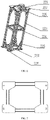
- FIG. 1 is a schematic structural diagram of a vehicle body chassis support provided by an embodiment of a system and a method for assembling a double-deck vehicle body according to the present invention
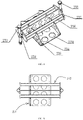
- FIG. 2 is a schematic structural diagram of an upper floor support provided by an embodiment of a system and a method for assembling a double-deck vehicle body according to the present invention
- FIG. 3 is a front view of a structure for an upper floor support provided by an embodiment of a system and a method for assembling a double-deck vehicle body according to the present invention.
- a system for assembling a double-deck vehicle body of according to an embodiment of the present invention includes: a vehicle body chassis support 1 and an upper floor support 2.
- the vehicle body chassis 1 support includes a crossbeam, an end support 11, and an intermediate support 12, where two ends of the crossbeam are respectively arranged with an end support 11, and the middle of the crossbeam is arranged the intermediate support 12; the height of the end support 11 is greater than that of the intermediate support 12; the upper surface of the end support 11 and the upper surface of the intermediate support 12 are configured to be closely fitted to the lower surface of the vehicle body chassis; and the upper floor support 2 is detachably arranged at the vehicle body chassis for supporting the upper floor of the vehicle body.
- the height of the end support 11 is greater than the height of the intermediate support 12 by a difference that equals to a difference between the heights of the two sides and the middle of the lower surface of the vehicle body chassis.
- the difference between the heights of the end support 11 and the intermediate support 12 depends on the specific condition of the vehicle body chassis.
- the length of the crossbeam of the present invention is determined by the length of the vehicle body chassis.
- the quantity and occupied length of the end supports 11 are determined by the length of the two sides of the vehicle body chassis.
- the quantity and occupied length of the intermediate supports 12 are determined by the length of the middle of the vehicle body chassis.
- the vehicle body chassis support of the system for assembling a double-deck vehicle body provided by the present invention includes the crossbeam, the end support, and the intermediate support.
- the end support has a greater height than the intermediate support, which can stabilize the double-deck vehicle body during the assembly process thereof and provides support for other components.
- the upper floor support connects the vehicle body chassis and the upper floor during the assembly process of the double-deck vehicle body, thereby supporting the upper floor to ensure the strength and rigidity of the cross section of the vehicle body.
- the crossbeam includes a first crossbeam 13 and a second crossbeam 14 arranged in parallel, with a plurality of connection crossbeams 15 arranged in parallel between the first crossbeam 13 and the second crossbeam 14.
- the connection crossbeam 15 is arranged the intermediate support 12, two ends of the first crossbeam 13 are arranged the end supports 11, and two ends of the second crossbeam 14 are arranged the end supports 11, respectively.
- the middle part of the double-deck aluminum alloy vehicle body chassis is a U-shaped structure.
- the first beam 13 and the second beam 14 are used to support both sides of the U-shaped vehicle body chassis, and the connection beam 15 is used to support the middle of the U-shaped floor.
- the quantity of connection beams 15 is six, and the distance between two adjacent connection beams 15 is 2.5 meters.
- the connection beams 15 are evenly distributed along the longitudinal direction of the vehicle body. The quantity and spacing of the connection beams 15 are based on the length of the middle part of the bottom of the vehicle body and the embodiment, and are not particularly limited herein.
- an upper part of the end support 11 is arranged a height adjustable screw 16.
- the screw 16 is provided so that the end support 11 may have some adjustability, and a worker can fine-tune the screw 16 to ensure that the end support 11 is in close contact with both sides of the vehicle body chassis.
- the upper floor support 2 includes a chassis connection frame 21, an intermediate support frame 22, and an upper support frame 23, and the width of the chassis connection frame 2 is narrower than that of the vehicle body.
- the upper floor support 2 is used to support the upper floor, assembling workers and equipment on the upper floor during the assembly work.
- the vehicle body chassis connecting frame 21 is located on the vehicle body chassis
- the intermediate support frame 22 is located on the vehicle body chassis connecting frame 21
- the upper support frame 23 is located on the intermediate support frame 22.
- the upper floor support 2 is a combined structure of the vehicle body chassis connecting frame 21, the intermediate support frame 22, and the upper support frame 23, and the three are detachably connected, which is convenient for assembly and use in the compartment of the carriage.
- FIG. 4 is a schematic structural diagram of a chassis connection frame provided by an embodiment of a system and a method for assembling a double-deck vehicle body according to the present invention
- FIG.5 is a front view of the chassis connection frame provided by the embodiment of a system and a method for assembling a double-deck vehicle body according to the present invention.
- the chassis connection frame 21 includes a first upper frame 211 and a first lower frame 212, which are connected through a first column 213. An end of the first upper frame 211 is connected with that of the first lower frame 212 through a first reinforcing plate 214.
- a stiffening plate 215 is arranged between the first upper frame 211 and the first column 213.
- a connection block 216 is arranged at the bottom of the first lower frame 212.
- a first connection plate 217 is arranged at the upper part of the first upper frame, and is provided with a connection hole.
- FIG.6 is a schematic structural diagram of an intermediate support frame provided by an embodiment of a system and a method for assembling a double-deck vehicle body according to the present invention
- FIG.7 is a top view of an intermediate support frame provided by an embodiment of a system and a method for assembling a double-deck vehicle body according to the present invention. As shown in FIG. 6 and
- the quantity of the intermediate support frames 22 is two, which are respectively located at both ends of the upper surface of the chassis connection frame 21.
- Each of the intermediate support frames 22 includes a second upper frame 221 and a second lower frame 222, which are connected by a second column 223.
- a reinforcing rib 224 is arranged between second columns 223.
- a second reinforcing plate 225 is arranged between the second columns 223 and the second upper frame 221, and between the second columns 223 and the second lower frame 222.
- a second connection plate 226 is arranged at a lower part of the second lower frame 222.
- a third connection plate 227 is arranged at an upper part of the second upper frame221. The second connection plate 226 and the third connection plate 227 are arranged with a connection hole.
- connection between the intermediate support frame 22 and the chassis connection frame 21 is implemented by bolts passing through the connection holes of the first connection plate 217 and the second connection plate 226.
- FIG. 8 is a schematic structural diagram of an upper support frame provided by an embodiment of a system and a method for assembling a double-deck vehicle body according to the present invention
- FIG. 9 is a top view of an upper support frame provided by an embodiment of a system and a method for assembling a double-deck vehicle body according to the present invention.
- each of the intermediate support frames 22, is arranged on top with an upper support frame 23, and each of the upper support frames 23 includes a fourth connection plate 231, an intermediate bracket 232, and a screw 233.
- the fourth connection plate 231 includes a bottom plate 234 and a side plate 235.
- the bottom plate 234 is arranged with a connection hole.
- the side plate 235 is arranged with a groove.
- the intermediate bracket 232 includes a support plate 236, and fifth connection plates 237 located on both ends of the support plate 236, and the support plate 236 engages with, and is welded to, the groove of the side plate 235.
- the screw 233 is connected to the fifth connection plate 237 through a bent connection plate 238.
- connection between the upper support frame 23 and the middle support frame 22 is connected by a bolt passing through the connection holes of the third connection plate 227 and the bottom plate 234.
- connection plate 231 and the intermediate bracket 232 are arranged with a weight reduction circular hole 239.
- the upper floor support 2 is realized by one chassis connection frame 21, two intermediate support frames 22, and two upper support frames 23, all of which joined by bolts, which facilitates installation and disassembly during the assembly process of the vehicle body. Moreover, by adapting the height of the second column 223 in the middle support frame 22 to the variations in the height of the upper floor, the fine adjustment of the height direction of the upper floor support 2 can be achieved by adjusting the height of the screw 233 in the upper support frame 23.
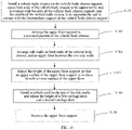
- FIG. 10 is a flowchart of a method for assembling a double-deck vehicle body provided by an embodiment of a system and a method for assembling a double-deck vehicle body according to the present invention. As shown in FIG. 10 , the method for assembling a double-deck vehicle body using the above-mentioned double-deck car body assembly system.
- the method for assembling a double-deck vehicle body includes:
- the quantity of the upper floor supports 2 in step S102 is three, and the three upper floor supports are respectively arranged at both ends and the middle of the lower recess of the vehicle body chassis.
- the vehicle body chassis support can stabilize the vehicle body chassis and provide a good support for the installation of other components.
- the upper floor support connects the vehicle body chassis and the upper floor during the assembly process of the double-deck vehicle body, thereby supporting the upper floor and ensuring the strength and rigidity of the cross section of the vehicle body.
- the upper floor support is easy to be installed and removed, and enables changing the width and height of the upper floor support according to the size of the vehicle body structure, so as to meet the requirements of vehicle bodies of various dimensions.
Landscapes
- Engineering & Computer Science (AREA)
- Chemical & Material Sciences (AREA)
- Combustion & Propulsion (AREA)
- Transportation (AREA)
- Mechanical Engineering (AREA)
- Manufacturing & Machinery (AREA)
- Body Structure For Vehicles (AREA)
Claims (9)
- Système d'assemblage d'une carrosserie d'un véhicule à deux étages, comportant : un support de châssis de carrosserie de véhicule (1) et un support de plancher supérieur (2), dans lequel :le support de châssis de carrosserie de véhicule (1) comprend une poutre transversale (13, 14), des supports d'extrémité (11), et un support intermédiaire (12), dans lequel les supports d'extrémité (11) sont agencés séparément au niveau de deux extrémités de la poutre transversale (13, 14), le support intermédiaire (12) est agencé au milieu de la poutre transversale (13, 14), une hauteur des supports d'extrémité (11) est supérieure à une hauteur du support intermédiaire (12), des surfaces supérieures des supports d'extrémité (11) et une surface supérieure du support intermédiaire (12) sont configurées pour être étroitement installées sur une surface inférieure d'un châssis de carrosserie de véhicule ; etle support de plancher supérieur (2) est agencé de manière détachable sur le châssis de carrosserie de véhicule à des fins de support d'un plancher supérieur de la carrosserie de véhicule.
- Système d'assemblage d'une carrosserie d'un véhicule à deux étages selon la revendication 1, dans lequel des parties supérieures des supports d'extrémité (11) sont agencées avec des vis réglables en hauteur (16).
- Système d'assemblage d'une carrosserie d'un véhicule à deux étages selon la revendication 1, dans lequel la poutre transversale (13, 14) comporte une première poutre transversale (13) et une deuxième poutre transversale (14) agencées en parallèle, et une pluralité de poutres transversales de raccordement (15) sont agencées en parallèle entre la première poutre transversale (13) et la deuxième poutre transversale (14) ; et
le support intermédiaire (12) est agencé sur les poutres transversales de raccordement (15), les supports d'extrémité (11) sont agencés séparément sur deux extrémités de la première poutre transversale (13) et deux extrémités de la deuxième poutre transversale (14). - Système d'assemblage d'une carrosserie d'un véhicule à deux étages selon la revendication 1, dans lequel le support de plancher supérieur (2) comporte un cadre de raccordement de châssis (21), un cadre de support intermédiaire (22), et un cadre de support supérieur (23), et une largeur du cadre de raccordement de châssis (21) est inférieure à une largeur d'une carrosserie de véhicule.
- Système d'assemblage d'une carrosserie d'un véhicule à deux étages selon la revendication 4, dans lequel :le cadre de raccordement de châssis (21) comporte un premier cadre supérieur (211) et un premier cadre inférieur (212), qui sont raccordés par une première colonne (213), une extrémité du premier cadre supérieur (211) est raccordée à une extrémité du premier cadre inférieur (212) par une première plaque de renfort (214), une plaque de raidissement (215) est agencée entre le premier cadre supérieur (211) et la première colonne (213), un bloc de raccordement (216) est agencé sur une partie inférieure du premier cadre inférieur (212), une première plaque de raccordement (217) est agencée sur une partie supérieure du premier cadre supérieur (211), et un trou de raccordement est agencé sur la première plaque de raccordement (217) ;le nombre de cadres de support intermédiaire (22) est de deux, cadres qui sont situés séparément au niveau de deux extrémités d'une surface supérieure du cadre de raccordement de châssis (21), chaque cadre de support intermédiaire (22) comporte un deuxième cadre supérieur (221) et un deuxième cadre inférieur (222), qui sont raccordés par des deuxièmes colonnes (223), une nervure de renfort (224) est agencée entre les deuxièmes colonnes (223), une deuxième plaque de renfort (225) est agencée entre la deuxième colonne (223) et le deuxième cadre supérieur (221), et entre la deuxième colonne (223) et le deuxième cadre inférieur (222), une deuxième plaque de raccordement (226) est agencée au niveau d'une partie inférieure du deuxième cadre inférieur (222), une troisième plaque de raccordement (227) est agencée au niveau d'une partie supérieure du deuxième cadre supérieur (221), et la deuxième plaque de raccordement (226) et la troisième plaque de raccordement (227) sont agencées avec un trou de raccordement ;un cadre de support supérieur (23) est agencé sur chaque cadre de support intermédiaire (22), et chaque cadre de support supérieur (23) comporte une quatrième plaque de raccordement (231), une console intermédiaire (232), et une vis (233), dans lequel la quatrième plaque de raccordement (231) comporte une plaque inférieure (234) et une plaque latérale (235), la plaque inférieure (234) est agencée avec un trou de raccordement, la plaque latérale (235) est agencée avec une rainure, la console intermédiaire (232) comporte une plaque de support (236), et des cinquièmes plaques de raccordement (237) situées des deux côtés de la plaque de support (236), et la plaque de support (236) se met en prise avec la rainure de la plaque latérale (235), et la vis (233) est raccordée à la cinquième plaque de raccordement (237) par une plaque de raccordement pliée (238).
- Système d'assemblage d'une carrosserie d'un véhicule à deux étages selon la revendication 5, dans lequel la quatrième plaque de raccordement (231) et la console intermédiaire (232) sont agencées avec un trou circulaire de réduction de poids (239).
- Système d'assemblage d'une carrosserie d'un véhicule à deux étages selon la revendication 1, dans lequel le support de plancher supérieur (2) est adapté pour se mettre en prise avec une partie en retrait du châssis de carrosserie de véhicule, dans lequel le nombre de supports de plancher supérieur (2) est de trois, dans lequel les trois supports de plancher supérieur (2) sont adaptés pour se mettre en prise avec les deux extrémités et une partie centrale, respectivement, d'une partie en retrait du châssis de carrosserie de véhicule.
- Procédé d'assemblage d'une carrosserie d'un véhicule à deux étages, dans lequel le procédé implique l'utilisation d'un système d'assemblage d'une carrosserie d'un véhicule à deux étages selon l'une quelconque des revendications 1 à 7, et le procédé comporte les étapes consistant à :installer (S101) un châssis de carrosserie de véhicule sur le support de châssis de carrosserie de véhicule (1), de telle sorte que les deux extrémités du châssis de carrosserie de véhicule sont supportées par, et sont en contact avec, des extrémités du support de châssis de carrosserie de véhicule (1), et une partie centrale du châssis de carrosserie de véhicule est supportée par, et est en contact avec, un support intermédiaire (12) du support de châssis de carrosserie de véhicule (1) ;agencer (S102) le support de plancher supérieur (2) dans une partie en retrait du châssis de carrosserie de véhicule ;agencer (S103) des parois latérales sur les deux côtés du châssis de carrosserie de véhicule, et un plancher supérieur entre deux parois latérales ;régler (S104) une hauteur du support de plancher supérieur (2), de telle sorte qu'une surface supérieure du support de plancher supérieur (2) est étroitement installée sur une surface inférieure du plancher supérieur ;installer (S 105) un toit par-dessus les parois latérales, et régler les hauteurs d'un premier étage de véhicule de transport et d'un deuxième étage de véhicule de transport ; etretirer (S 106) le support de plancher supérieur (2).
- Procédé d'assemblage d'une carrosserie d'un véhicule à deux étages selon la revendication 8, dans lequel le nombre de supports de plancher supérieur (2) est de trois, et l'étape consistant à agencer (S102) le support de plancher supérieur (2) dans une partie en retrait du châssis de carrosserie de véhicule comporte :
l'étape consistant à agencer les trois supports de plancher supérieur (2) au niveau de deux extrémités et d'une partie centrale, respectivement, de la partie en retrait du châssis de carrosserie de véhicule.
Applications Claiming Priority (2)
| Application Number | Priority Date | Filing Date | Title |
|---|---|---|---|
| CN201710693833.4A CN107458501B (zh) | 2017-08-14 | 2017-08-14 | 双层车体装配系统及方法 |
| PCT/CN2017/117620 WO2019033670A1 (fr) | 2017-08-14 | 2017-12-21 | Système et procédé d'assemblage d'un corps de véhicule à deux étages |
Publications (3)
| Publication Number | Publication Date |
|---|---|
| EP3659903A1 EP3659903A1 (fr) | 2020-06-03 |
| EP3659903A4 EP3659903A4 (fr) | 2020-12-02 |
| EP3659903B1 true EP3659903B1 (fr) | 2022-04-20 |
Family
ID=60549629
Family Applications (1)
| Application Number | Title | Priority Date | Filing Date |
|---|---|---|---|
| EP17921832.6A Active EP3659903B1 (fr) | 2017-08-14 | 2017-12-21 | Système et procédé d'assemblage d'un corps de véhicule à deux étages |
Country Status (5)
| Country | Link |
|---|---|
| US (1) | US11352080B2 (fr) |
| EP (1) | EP3659903B1 (fr) |
| CN (1) | CN107458501B (fr) |
| PT (1) | PT3659903T (fr) |
| WO (1) | WO2019033670A1 (fr) |
Families Citing this family (4)
| Publication number | Priority date | Publication date | Assignee | Title |
|---|---|---|---|---|
| CN107458501B (zh) * | 2017-08-14 | 2019-04-23 | 中车唐山机车车辆有限公司 | 双层车体装配系统及方法 |
| CN111775989B (zh) * | 2019-04-03 | 2021-07-27 | 中车唐山机车车辆有限公司 | 一种双层轨道车辆及其车体 |
| CN112092851B (zh) * | 2020-09-01 | 2021-11-02 | 中车长春轨道客车股份有限公司 | 底架合成定位装置及其定位方法 |
| CN112355992A (zh) * | 2020-10-22 | 2021-02-12 | 中车青岛四方机车车辆股份有限公司 | 一种轨道交通列车司机室存放支撑工装及方法 |
Family Cites Families (16)
| Publication number | Priority date | Publication date | Assignee | Title |
|---|---|---|---|---|
| BE678577A (fr) * | 1965-04-27 | 1966-09-01 | ||
| US4033033A (en) * | 1976-02-23 | 1977-07-05 | Rohr Industries, Inc. | Bus manufacturing mechanism and method |
| JPS6112474A (ja) * | 1984-06-26 | 1986-01-20 | Toyota Motor Corp | 車体組立装置 |
| JP2831999B2 (ja) * | 1987-12-01 | 1998-12-02 | マツダ株式会社 | 自動車組立ラインの足回り部組付装置 |
| WO2009132363A1 (fr) * | 2008-04-22 | 2009-10-29 | Singh, Rene | Montage pour la fabrication de châssis de bus |
| JP5263535B2 (ja) * | 2009-06-25 | 2013-08-14 | 近畿車輌株式会社 | 低床車両の連結器設置構造 |
| CN101624073B (zh) * | 2009-08-18 | 2011-02-09 | 安徽安凯汽车股份有限公司 | 双层客车骨架车身装配方法 |
| US8839507B2 (en) * | 2009-12-15 | 2014-09-23 | Comau, Inc. | Remote locking apparatus for securing a vehicle body to a vehicle body support |
| DE102010000777A1 (de) * | 2010-01-11 | 2011-07-14 | Ford Global Technologies, LLC, Mich. | Verfahren zur Montage eines Karosseriebauteils an eine Rohkarosserie und Halter |
| WO2011137283A2 (fr) * | 2010-04-30 | 2011-11-03 | Comau, Inc | Dispositif fixe d'assemblage de carrosserie de véhicule variable et procédé |
| CN202162519U (zh) * | 2011-05-17 | 2012-03-14 | 南方汇通股份有限公司 | 一种铁路货车底架模块化组装夹具 |
| CN202846091U (zh) * | 2012-10-29 | 2013-04-03 | 湘潭电机股份有限公司 | 一种低地板车的凹型底架焊接组合夹具 |
| DE102013112152B4 (de) * | 2013-11-05 | 2024-09-19 | Deutsches Zentrum für Luft- und Raumfahrt e.V. | Fahrzeug und Wagenkasten für ein Fahrzeug |
| CN104097009B (zh) * | 2014-07-15 | 2016-01-13 | 南车南京浦镇车辆有限公司 | 通用式底架正装胎 |
| CN205465154U (zh) * | 2016-02-23 | 2016-08-17 | 中车青岛四方机车车辆股份有限公司 | 轨道车辆不锈钢车体组装装置 |
| CN107458501B (zh) * | 2017-08-14 | 2019-04-23 | 中车唐山机车车辆有限公司 | 双层车体装配系统及方法 |
-
2017
- 2017-08-14 CN CN201710693833.4A patent/CN107458501B/zh active Active
- 2017-12-21 EP EP17921832.6A patent/EP3659903B1/fr active Active
- 2017-12-21 PT PT179218326T patent/PT3659903T/pt unknown
- 2017-12-21 WO PCT/CN2017/117620 patent/WO2019033670A1/fr not_active Ceased
-
2020
- 2020-02-14 US US16/791,847 patent/US11352080B2/en active Active
Also Published As
| Publication number | Publication date |
|---|---|
| US20200180715A1 (en) | 2020-06-11 |
| US11352080B2 (en) | 2022-06-07 |
| CN107458501A (zh) | 2017-12-12 |
| PT3659903T (pt) | 2022-05-09 |
| WO2019033670A1 (fr) | 2019-02-21 |
| EP3659903A4 (fr) | 2020-12-02 |
| EP3659903A1 (fr) | 2020-06-03 |
| CN107458501B (zh) | 2019-04-23 |
Similar Documents
| Publication | Publication Date | Title |
|---|---|---|
| US11352080B2 (en) | System and method for assembling double-deck vehicle body | |
| CN103118920B (zh) | 用于轨道车辆的车厢及其制造方法 | |
| CN111232002A (zh) | 模块化轨道车辆车体 | |
| CN101643087B (zh) | 具有底板加强件的汽车车身 | |
| US4275663A (en) | Corrugated vehicle underframe | |
| CN104097647A (zh) | 一种铁路专用多功能卷钢运输车 | |
| CA2907212C (fr) | Wagon porte-automobiles a capacite variable | |
| CN101559775A (zh) | 车身结构 | |
| RU2438910C2 (ru) | Интегральный грузовой отсек кузова транспортного средства | |
| CN103465921A (zh) | 一种快捷集装箱运输的专用车车体 | |
| CN213292296U (zh) | 一种铁路车辆、铁路车辆的底架及侧梁 | |
| CN104228858A (zh) | 一种运输车辆及其车体 | |
| RU176585U1 (ru) | Вагон-цистерна | |
| RU2288121C1 (ru) | Железнодорожная платформа для перевозки крупнотоннажных контейнеров | |
| US6641206B1 (en) | Load carrying arrangement for a vehicle | |
| CN109440549B (zh) | 一种悬挂式单轨交通系统及其轨道梁 | |
| CN114228842B (zh) | 新能源物流车、车厢和底架总成 | |
| CN105835899B (zh) | 一种牵引拉杆安装接口装置及转向架 | |
| CN203958145U (zh) | 一种铁路专用多功能卷钢运输车 | |
| CN210912156U (zh) | 轻量化车厢底部防护钢板的连接结构 | |
| CN110789549B (zh) | 端墙结构及具有其的有轨电车 | |
| CN109263670B (zh) | 一种低地板轨道车辆顶盖及低地板轨道车辆 | |
| CN221068070U (zh) | 车体底架边梁 | |
| CN107738692B (zh) | 一种铝合金侧帘半挂车的型材边梁及其车架 | |
| CN206493954U (zh) | 一种牵引拉杆安装接口装置及转向架 |
Legal Events
| Date | Code | Title | Description |
|---|---|---|---|
| STAA | Information on the status of an ep patent application or granted ep patent |
Free format text: STATUS: THE INTERNATIONAL PUBLICATION HAS BEEN MADE |
|
| PUAI | Public reference made under article 153(3) epc to a published international application that has entered the european phase |
Free format text: ORIGINAL CODE: 0009012 |
|
| STAA | Information on the status of an ep patent application or granted ep patent |
Free format text: STATUS: REQUEST FOR EXAMINATION WAS MADE |
|
| 17P | Request for examination filed |
Effective date: 20200225 |
|
| AK | Designated contracting states |
Kind code of ref document: A1 Designated state(s): AL AT BE BG CH CY CZ DE DK EE ES FI FR GB GR HR HU IE IS IT LI LT LU LV MC MK MT NL NO PL PT RO RS SE SI SK SM TR |
|
| AX | Request for extension of the european patent |
Extension state: BA ME |
|
| DAV | Request for validation of the european patent (deleted) | ||
| DAX | Request for extension of the european patent (deleted) | ||
| A4 | Supplementary search report drawn up and despatched |
Effective date: 20201030 |
|
| RIC1 | Information provided on ipc code assigned before grant |
Ipc: B62D 65/02 20060101AFI20201026BHEP Ipc: B62D 31/04 20060101ALI20201026BHEP Ipc: B62D 31/02 20060101ALI20201026BHEP |
|
| RIC1 | Information provided on ipc code assigned before grant |
Ipc: B62D 65/02 20060101AFI20210712BHEP Ipc: B62D 31/02 20060101ALI20210712BHEP Ipc: B62D 31/04 20060101ALI20210712BHEP |
|
| GRAP | Despatch of communication of intention to grant a patent |
Free format text: ORIGINAL CODE: EPIDOSNIGR1 |
|
| STAA | Information on the status of an ep patent application or granted ep patent |
Free format text: STATUS: GRANT OF PATENT IS INTENDED |
|
| INTG | Intention to grant announced |
Effective date: 20210906 |
|
| GRAJ | Information related to disapproval of communication of intention to grant by the applicant or resumption of examination proceedings by the epo deleted |
Free format text: ORIGINAL CODE: EPIDOSDIGR1 |
|
| STAA | Information on the status of an ep patent application or granted ep patent |
Free format text: STATUS: REQUEST FOR EXAMINATION WAS MADE |
|
| INTC | Intention to grant announced (deleted) | ||
| GRAP | Despatch of communication of intention to grant a patent |
Free format text: ORIGINAL CODE: EPIDOSNIGR1 |
|
| STAA | Information on the status of an ep patent application or granted ep patent |
Free format text: STATUS: GRANT OF PATENT IS INTENDED |
|
| INTG | Intention to grant announced |
Effective date: 20220128 |
|
| GRAS | Grant fee paid |
Free format text: ORIGINAL CODE: EPIDOSNIGR3 |
|
| GRAA | (expected) grant |
Free format text: ORIGINAL CODE: 0009210 |
|
| STAA | Information on the status of an ep patent application or granted ep patent |
Free format text: STATUS: THE PATENT HAS BEEN GRANTED |
|
| AK | Designated contracting states |
Kind code of ref document: B1 Designated state(s): AL AT BE BG CH CY CZ DE DK EE ES FI FR GB GR HR HU IE IS IT LI LT LU LV MC MK MT NL NO PL PT RO RS SE SI SK SM TR |
|
| REG | Reference to a national code |
Ref country code: GB Ref legal event code: FG4D |
|
| REG | Reference to a national code |
Ref country code: CH Ref legal event code: EP |
|
| REG | Reference to a national code |
Ref country code: PT Ref legal event code: SC4A Ref document number: 3659903 Country of ref document: PT Date of ref document: 20220509 Kind code of ref document: T Free format text: AVAILABILITY OF NATIONAL TRANSLATION Effective date: 20220502 |
|
| REG | Reference to a national code |
Ref country code: IE Ref legal event code: FG4D |
|
| REG | Reference to a national code |
Ref country code: DE Ref legal event code: R096 Ref document number: 602017056406 Country of ref document: DE |
|
| REG | Reference to a national code |
Ref country code: AT Ref legal event code: REF Ref document number: 1484974 Country of ref document: AT Kind code of ref document: T Effective date: 20220515 |
|
| REG | Reference to a national code |
Ref country code: LT Ref legal event code: MG9D |
|
| REG | Reference to a national code |
Ref country code: NL Ref legal event code: MP Effective date: 20220420 |
|
| REG | Reference to a national code |
Ref country code: AT Ref legal event code: MK05 Ref document number: 1484974 Country of ref document: AT Kind code of ref document: T Effective date: 20220420 |
|
| PG25 | Lapsed in a contracting state [announced via postgrant information from national office to epo] |
Ref country code: NL Free format text: LAPSE BECAUSE OF FAILURE TO SUBMIT A TRANSLATION OF THE DESCRIPTION OR TO PAY THE FEE WITHIN THE PRESCRIBED TIME-LIMIT Effective date: 20220420 |
|
| PG25 | Lapsed in a contracting state [announced via postgrant information from national office to epo] |
Ref country code: SE Free format text: LAPSE BECAUSE OF FAILURE TO SUBMIT A TRANSLATION OF THE DESCRIPTION OR TO PAY THE FEE WITHIN THE PRESCRIBED TIME-LIMIT Effective date: 20220420 Ref country code: NO Free format text: LAPSE BECAUSE OF FAILURE TO SUBMIT A TRANSLATION OF THE DESCRIPTION OR TO PAY THE FEE WITHIN THE PRESCRIBED TIME-LIMIT Effective date: 20220720 Ref country code: LT Free format text: LAPSE BECAUSE OF FAILURE TO SUBMIT A TRANSLATION OF THE DESCRIPTION OR TO PAY THE FEE WITHIN THE PRESCRIBED TIME-LIMIT Effective date: 20220420 Ref country code: HR Free format text: LAPSE BECAUSE OF FAILURE TO SUBMIT A TRANSLATION OF THE DESCRIPTION OR TO PAY THE FEE WITHIN THE PRESCRIBED TIME-LIMIT Effective date: 20220420 Ref country code: GR Free format text: LAPSE BECAUSE OF FAILURE TO SUBMIT A TRANSLATION OF THE DESCRIPTION OR TO PAY THE FEE WITHIN THE PRESCRIBED TIME-LIMIT Effective date: 20220721 Ref country code: FI Free format text: LAPSE BECAUSE OF FAILURE TO SUBMIT A TRANSLATION OF THE DESCRIPTION OR TO PAY THE FEE WITHIN THE PRESCRIBED TIME-LIMIT Effective date: 20220420 Ref country code: ES Free format text: LAPSE BECAUSE OF FAILURE TO SUBMIT A TRANSLATION OF THE DESCRIPTION OR TO PAY THE FEE WITHIN THE PRESCRIBED TIME-LIMIT Effective date: 20220420 Ref country code: BG Free format text: LAPSE BECAUSE OF FAILURE TO SUBMIT A TRANSLATION OF THE DESCRIPTION OR TO PAY THE FEE WITHIN THE PRESCRIBED TIME-LIMIT Effective date: 20220720 Ref country code: AT Free format text: LAPSE BECAUSE OF FAILURE TO SUBMIT A TRANSLATION OF THE DESCRIPTION OR TO PAY THE FEE WITHIN THE PRESCRIBED TIME-LIMIT Effective date: 20220420 |
|
| PG25 | Lapsed in a contracting state [announced via postgrant information from national office to epo] |
Ref country code: RS Free format text: LAPSE BECAUSE OF FAILURE TO SUBMIT A TRANSLATION OF THE DESCRIPTION OR TO PAY THE FEE WITHIN THE PRESCRIBED TIME-LIMIT Effective date: 20220420 Ref country code: PL Free format text: LAPSE BECAUSE OF FAILURE TO SUBMIT A TRANSLATION OF THE DESCRIPTION OR TO PAY THE FEE WITHIN THE PRESCRIBED TIME-LIMIT Effective date: 20220420 Ref country code: LV Free format text: LAPSE BECAUSE OF FAILURE TO SUBMIT A TRANSLATION OF THE DESCRIPTION OR TO PAY THE FEE WITHIN THE PRESCRIBED TIME-LIMIT Effective date: 20220420 Ref country code: IS Free format text: LAPSE BECAUSE OF FAILURE TO SUBMIT A TRANSLATION OF THE DESCRIPTION OR TO PAY THE FEE WITHIN THE PRESCRIBED TIME-LIMIT Effective date: 20220820 |
|
| REG | Reference to a national code |
Ref country code: DE Ref legal event code: R097 Ref document number: 602017056406 Country of ref document: DE |
|
| PG25 | Lapsed in a contracting state [announced via postgrant information from national office to epo] |
Ref country code: SM Free format text: LAPSE BECAUSE OF FAILURE TO SUBMIT A TRANSLATION OF THE DESCRIPTION OR TO PAY THE FEE WITHIN THE PRESCRIBED TIME-LIMIT Effective date: 20220420 Ref country code: SK Free format text: LAPSE BECAUSE OF FAILURE TO SUBMIT A TRANSLATION OF THE DESCRIPTION OR TO PAY THE FEE WITHIN THE PRESCRIBED TIME-LIMIT Effective date: 20220420 Ref country code: RO Free format text: LAPSE BECAUSE OF FAILURE TO SUBMIT A TRANSLATION OF THE DESCRIPTION OR TO PAY THE FEE WITHIN THE PRESCRIBED TIME-LIMIT Effective date: 20220420 Ref country code: EE Free format text: LAPSE BECAUSE OF FAILURE TO SUBMIT A TRANSLATION OF THE DESCRIPTION OR TO PAY THE FEE WITHIN THE PRESCRIBED TIME-LIMIT Effective date: 20220420 Ref country code: DK Free format text: LAPSE BECAUSE OF FAILURE TO SUBMIT A TRANSLATION OF THE DESCRIPTION OR TO PAY THE FEE WITHIN THE PRESCRIBED TIME-LIMIT Effective date: 20220420 Ref country code: CZ Free format text: LAPSE BECAUSE OF FAILURE TO SUBMIT A TRANSLATION OF THE DESCRIPTION OR TO PAY THE FEE WITHIN THE PRESCRIBED TIME-LIMIT Effective date: 20220420 |
|
| PGFP | Annual fee paid to national office [announced via postgrant information from national office to epo] |
Ref country code: TR Payment date: 20221123 Year of fee payment: 6 |
|
| PLBE | No opposition filed within time limit |
Free format text: ORIGINAL CODE: 0009261 |
|
| STAA | Information on the status of an ep patent application or granted ep patent |
Free format text: STATUS: NO OPPOSITION FILED WITHIN TIME LIMIT |
|
| 26N | No opposition filed |
Effective date: 20230123 |
|
| PG25 | Lapsed in a contracting state [announced via postgrant information from national office to epo] |
Ref country code: AL Free format text: LAPSE BECAUSE OF FAILURE TO SUBMIT A TRANSLATION OF THE DESCRIPTION OR TO PAY THE FEE WITHIN THE PRESCRIBED TIME-LIMIT Effective date: 20220420 |
|
| PG25 | Lapsed in a contracting state [announced via postgrant information from national office to epo] |
Ref country code: SI Free format text: LAPSE BECAUSE OF FAILURE TO SUBMIT A TRANSLATION OF THE DESCRIPTION OR TO PAY THE FEE WITHIN THE PRESCRIBED TIME-LIMIT Effective date: 20220420 |
|
| REG | Reference to a national code |
Ref country code: CH Ref legal event code: PL |
|
| GBPC | Gb: european patent ceased through non-payment of renewal fee |
Effective date: 20221221 |
|
| REG | Reference to a national code |
Ref country code: BE Ref legal event code: MM Effective date: 20221231 |
|
| PG25 | Lapsed in a contracting state [announced via postgrant information from national office to epo] |
Ref country code: LU Free format text: LAPSE BECAUSE OF NON-PAYMENT OF DUE FEES Effective date: 20221221 |
|
| PG25 | Lapsed in a contracting state [announced via postgrant information from national office to epo] |
Ref country code: LI Free format text: LAPSE BECAUSE OF NON-PAYMENT OF DUE FEES Effective date: 20221231 Ref country code: IE Free format text: LAPSE BECAUSE OF NON-PAYMENT OF DUE FEES Effective date: 20221221 Ref country code: GB Free format text: LAPSE BECAUSE OF NON-PAYMENT OF DUE FEES Effective date: 20221221 Ref country code: CH Free format text: LAPSE BECAUSE OF NON-PAYMENT OF DUE FEES Effective date: 20221231 |
|
| PG25 | Lapsed in a contracting state [announced via postgrant information from national office to epo] |
Ref country code: FR Free format text: LAPSE BECAUSE OF NON-PAYMENT OF DUE FEES Effective date: 20221231 Ref country code: BE Free format text: LAPSE BECAUSE OF NON-PAYMENT OF DUE FEES Effective date: 20221231 |
|
| PG25 | Lapsed in a contracting state [announced via postgrant information from national office to epo] |
Ref country code: HU Free format text: LAPSE BECAUSE OF FAILURE TO SUBMIT A TRANSLATION OF THE DESCRIPTION OR TO PAY THE FEE WITHIN THE PRESCRIBED TIME-LIMIT; INVALID AB INITIO Effective date: 20171221 |
|
| PG25 | Lapsed in a contracting state [announced via postgrant information from national office to epo] |
Ref country code: CY Free format text: LAPSE BECAUSE OF FAILURE TO SUBMIT A TRANSLATION OF THE DESCRIPTION OR TO PAY THE FEE WITHIN THE PRESCRIBED TIME-LIMIT Effective date: 20220420 |
|
| PG25 | Lapsed in a contracting state [announced via postgrant information from national office to epo] |
Ref country code: MK Free format text: LAPSE BECAUSE OF FAILURE TO SUBMIT A TRANSLATION OF THE DESCRIPTION OR TO PAY THE FEE WITHIN THE PRESCRIBED TIME-LIMIT Effective date: 20220420 |
|
| PG25 | Lapsed in a contracting state [announced via postgrant information from national office to epo] |
Ref country code: MC Free format text: LAPSE BECAUSE OF FAILURE TO SUBMIT A TRANSLATION OF THE DESCRIPTION OR TO PAY THE FEE WITHIN THE PRESCRIBED TIME-LIMIT Effective date: 20220420 |
|
| PG25 | Lapsed in a contracting state [announced via postgrant information from national office to epo] |
Ref country code: MC Free format text: LAPSE BECAUSE OF FAILURE TO SUBMIT A TRANSLATION OF THE DESCRIPTION OR TO PAY THE FEE WITHIN THE PRESCRIBED TIME-LIMIT Effective date: 20220420 |
|
| PG25 | Lapsed in a contracting state [announced via postgrant information from national office to epo] |
Ref country code: MT Free format text: LAPSE BECAUSE OF FAILURE TO SUBMIT A TRANSLATION OF THE DESCRIPTION OR TO PAY THE FEE WITHIN THE PRESCRIBED TIME-LIMIT Effective date: 20220420 |
|
| PG25 | Lapsed in a contracting state [announced via postgrant information from national office to epo] |
Ref country code: BG Free format text: LAPSE BECAUSE OF FAILURE TO SUBMIT A TRANSLATION OF THE DESCRIPTION OR TO PAY THE FEE WITHIN THE PRESCRIBED TIME-LIMIT Effective date: 20220420 |
|
| PG25 | Lapsed in a contracting state [announced via postgrant information from national office to epo] |
Ref country code: BG Free format text: LAPSE BECAUSE OF FAILURE TO SUBMIT A TRANSLATION OF THE DESCRIPTION OR TO PAY THE FEE WITHIN THE PRESCRIBED TIME-LIMIT Effective date: 20220420 |
|
| PGFP | Annual fee paid to national office [announced via postgrant information from national office to epo] |
Ref country code: PT Payment date: 20251120 Year of fee payment: 9 |
|
| PGFP | Annual fee paid to national office [announced via postgrant information from national office to epo] |
Ref country code: IT Payment date: 20251210 Year of fee payment: 9 |
|
| PGFP | Annual fee paid to national office [announced via postgrant information from national office to epo] |
Ref country code: DE Payment date: 20251231 Year of fee payment: 9 |