EP3660574A1 - Scanning device - Google Patents
Scanning device Download PDFInfo
- Publication number
- EP3660574A1 EP3660574A1 EP18838227.9A EP18838227A EP3660574A1 EP 3660574 A1 EP3660574 A1 EP 3660574A1 EP 18838227 A EP18838227 A EP 18838227A EP 3660574 A1 EP3660574 A1 EP 3660574A1
- Authority
- EP
- European Patent Office
- Prior art keywords
- drive signal
- period
- signal
- mirror
- control unit
- Prior art date
- Legal status (The legal status is an assumption and is not a legal conclusion. Google has not performed a legal analysis and makes no representation as to the accuracy of the status listed.)
- Pending
Links
- 230000007246 mechanism Effects 0.000 claims abstract description 53
- 230000004048 modification Effects 0.000 description 12
- 238000012986 modification Methods 0.000 description 12
- 238000009792 diffusion process Methods 0.000 description 11
- 238000012544 monitoring process Methods 0.000 description 10
- 230000000977 initiatory effect Effects 0.000 description 7
- 230000003287 optical effect Effects 0.000 description 5
- 238000010586 diagram Methods 0.000 description 3
- 238000005516 engineering process Methods 0.000 description 3
- 238000005259 measurement Methods 0.000 description 3
- 230000000694 effects Effects 0.000 description 2
- 230000007274 generation of a signal involved in cell-cell signaling Effects 0.000 description 2
- 238000000034 method Methods 0.000 description 2
- 230000008569 process Effects 0.000 description 2
- 238000010521 absorption reaction Methods 0.000 description 1
- 230000032683 aging Effects 0.000 description 1
- 230000008901 benefit Effects 0.000 description 1
- 230000005540 biological transmission Effects 0.000 description 1
- 230000000052 comparative effect Effects 0.000 description 1
- 239000000835 fiber Substances 0.000 description 1
- 230000006870 function Effects 0.000 description 1
- 239000012212 insulator Substances 0.000 description 1
- 238000004519 manufacturing process Methods 0.000 description 1
- 239000002184 metal Substances 0.000 description 1
- 239000002245 particle Substances 0.000 description 1
- 230000009467 reduction Effects 0.000 description 1
- 239000004065 semiconductor Substances 0.000 description 1
- 229910052710 silicon Inorganic materials 0.000 description 1
- 239000010703 silicon Substances 0.000 description 1
- 239000000758 substrate Substances 0.000 description 1
- 238000004804 winding Methods 0.000 description 1
Images




Classifications
-
- G—PHYSICS
- G02—OPTICS
- G02B—OPTICAL ELEMENTS, SYSTEMS OR APPARATUS
- G02B26/00—Optical devices or arrangements for the control of light using movable or deformable optical elements
- G02B26/08—Optical devices or arrangements for the control of light using movable or deformable optical elements for controlling the direction of light
- G02B26/10—Scanning systems
- G02B26/101—Scanning systems with both horizontal and vertical deflecting means, e.g. raster or XY scanners
-
- B—PERFORMING OPERATIONS; TRANSPORTING
- B81—MICROSTRUCTURAL TECHNOLOGY
- B81B—MICROSTRUCTURAL DEVICES OR SYSTEMS, e.g. MICROMECHANICAL DEVICES
- B81B3/00—Devices comprising flexible or deformable elements, e.g. comprising elastic tongues or membranes
-
- G—PHYSICS
- G02—OPTICS
- G02B—OPTICAL ELEMENTS, SYSTEMS OR APPARATUS
- G02B26/00—Optical devices or arrangements for the control of light using movable or deformable optical elements
- G02B26/08—Optical devices or arrangements for the control of light using movable or deformable optical elements for controlling the direction of light
- G02B26/0816—Optical devices or arrangements for the control of light using movable or deformable optical elements for controlling the direction of light by means of one or more reflecting elements
- G02B26/0833—Optical devices or arrangements for the control of light using movable or deformable optical elements for controlling the direction of light by means of one or more reflecting elements the reflecting element being a micromechanical device, e.g. a MEMS mirror, DMD
- G02B26/085—Optical devices or arrangements for the control of light using movable or deformable optical elements for controlling the direction of light by means of one or more reflecting elements the reflecting element being a micromechanical device, e.g. a MEMS mirror, DMD the reflecting means being moved or deformed by electromagnetic means
-
- G—PHYSICS
- G02—OPTICS
- G02B—OPTICAL ELEMENTS, SYSTEMS OR APPARATUS
- G02B26/00—Optical devices or arrangements for the control of light using movable or deformable optical elements
- G02B26/08—Optical devices or arrangements for the control of light using movable or deformable optical elements for controlling the direction of light
- G02B26/10—Scanning systems
- G02B26/105—Scanning systems with one or more pivoting mirrors or galvano-mirrors
-
- H—ELECTRICITY
- H04—ELECTRIC COMMUNICATION TECHNIQUE
- H04N—PICTORIAL COMMUNICATION, e.g. TELEVISION
- H04N9/00—Details of colour television systems
- H04N9/12—Picture reproducers
- H04N9/31—Projection devices for colour picture display, e.g. using electronic spatial light modulators [ESLM]
- H04N9/3129—Projection devices for colour picture display, e.g. using electronic spatial light modulators [ESLM] scanning a light beam on the display screen
- H04N9/3135—Driving therefor
Definitions
- the present disclosure relates to a scanning device.
- a scanning device for example, a scanning device that performs scanning with laser light by using a MEMS (micro electro mechanical systems) mirror mechanism to display an image is known.
- the scanning device for example, an image of one frame or two frames is formed by m times of reciprocation ( m : an integer of two or greater) of an irradiation region of laser light in a horizontal direction, and one time of reciprocation of the irradiation region of the laser light in a vertical direction.
- Patent Literature 1 discloses a technology in which synchronization is performed at the time of initiating one frame and at the time of terminating one frame between a horizontal drive signal and a vertical drive signal for driving the MEMS mirror mechanism.
- Patent Literature 1 Japanese Unexamined Patent Publication No. 2006-276634
- An object of the present disclosure is to provide a scanning device capable of realizing stable scanning with laser light.
- a scanning device includes: a light source that emits laser light; an MEMS mirror mechanism that includes a mirror that reflects the laser light emitted from the light source, reciprocates an irradiation region of the laser light in a first direction by swinging the mirror with respect to a first axial line as a central line, and reciprocates the irradiation region in a second direction that intersects the first direction by swinging the mirror with respect to a second axial line as a central line that intersects the first axial line; and a control unit that generates a first drive signal for swinging the mirror with respect to the first axial line as a central line and a second drive signal for swinging the mirror with respect to the second axial line as a central line, and inputs the first drive signal and the second drive signal to the MEMS mirror mechanism.
- the first drive signal is an electric signal in which one swing of the mirror with respect to the first axial line as a central line is set as one cycle
- the second drive signal is an electric signal in which one swing of the mirror with respect to the second axial line as a central line is set as one cycle
- the control unit generates a second signal element constituting the second drive signal to correspond to a first signal element in a period equal to or less than one cycle period in the first drive signal, and repeats generation of the second signal element in both an outgoing period and an incoming period in the one swing of the mirror with respect to the second axial line as a central line to generate the first drive signal and the second drive signal so that m times of reciprocation ( m : an integer of two or greater) of the irradiation region in the first direction and one time of reciprocation of the irradiation region in the second direction correspond to each other.
- the second signal element constituting the second drive signal is generated to correspond to the first signal element in a period equal to or less than one cycle period in the first drive signal.
- generation of the second signal element is repeated in both an outgoing period and an incoming period in the one swing of the mirror with respect to the second axial line as a central line. According to this, even when the MEMS mirror mechanism is influenced by a variation of an ambient temperature or the like, it is possible to suppress occurrence of a deviation in a corresponding relationship between the first drive signal and the second drive signal. Accordingly, according to the scanning device, stable scanning with laser light becomes possible.
- the first drive signal may be an electric signal for resonating the mirror with respect to the first axial line as a central line
- the second drive signal may be an electric signal for linearly operating the mirror with respect to the second axial line as a central line
- the control unit may modulate a frequency of the first drive signal to conform to a resonance frequency of the mirror.
- the control unit may control the light source so that the outgoing period corresponds to a lighting-on period and the incoming period corresponds to a lighting-off period, and may repeat generation of the second signal element in the both lighting-on period and the lighting-off period. According to this, it is possible to suppress occurrence of a deviation in a corresponding relationship between the first drive signal and the second drive signal in the respective lighting-on periods.
- the lighting-on period is a period in which the control unit causes the light source to emit laser light
- the lighting-off period is a period in which the control unit does not cause the light source to emit the laser light.
- the control unit may control the light source so that the outgoing period corresponds to a first lighting-on period and the incoming period corresponds to a second lighting-on period, and may repeat generation of the second signal element in both the first lighting-on period and the second lighting-on period. According to this, it is possible to suppress occurrence of the deviation in the corresponding relationship between the first drive signal and the second drive signal in the first lighting-on period and the second lighting-on period.
- the first lighting-on period and the second lighting-on period are periods in which the control unit causes the light source to emit laser light.
- control unit may generate the second signal element to correspond to the first signal element in a 1/2 cycle period in the first drive signal.
- the control unit may generate the second signal element to correspond to the first signal element in a one cycle period in the first drive signal. According to this, it is possible to make a process when generating the second signal element easy.
- control unit may generate the second signal element to correspond to the first signal element in a current one cycle period in the first drive signal.
- the control unit may generate the second signal element to correspond to the first signal element in an immediately previous one cycle period in the first drive signal. According to this, time delay when generating the second signal element can be minimized.
- the MEMS mirror mechanism may include a first movable unit provided with the mirror, a second movable unit that supports the first movable unit to be swingable with respect to the first axial line as a central line, a support unit that supports the second movable unit to be swingable with respect to the second axial line as a central line, a drive coil that is provided in the second movable unit, and a magnet that generates a magnetic field acting on the drive coil.
- the electromagnetic drive type MEMS mirror mechanism is susceptible to a variation of an ambient temperature or the like, and thus repetition of generation of the second signal element as described above is particularly effective.
- the light source may emit the laser light for projection display
- the control unit may generate the first drive signal and the second drive signal so that an image of one frame or two frames is formed by the m times of reciprocation of the irradiation region in the first direction and the one time of reciprocation of the irradiation region in the second direction.
- control unit may control the light source so that the laser light is modulated in correspondence with a position of the irradiation region. According to this, image display with higher quality is possible.
- control unit may repeat generation of the second signal element while fluctuating a frame rate. According to this, it is possible to easily and reliably repeat generation of the second signal element.
- a scanning display system 10 is a laser scanning projection display that is mounted on a vehicle, and displays (projects and displays) an image to a windshield 100 of the vehicle.
- the scanning display system 10 includes a scanning device 1 and an optical system 11.
- the optical system 11 includes a plurality of planar mirrors 11a and 11b, a concave mirror 11c, and a windshield 100.
- the windshield 100 functions as an optical element on a rearmost stage in the optical system 11.
- Light L2 for projection display which is emitted from the scanning device 1 is sequentially reflected by the planar mirror 11a, the planar mirror 11b, the concave mirror 11c, and the windshield 100, and is incident to an eye E of an observer.
- the scanning device 1 includes a light source 2, a MEMS mirror mechanism 3, a light diffusion unit 4, and a control unit 5.
- the light source 2 emits laser light L1 for projection display. More specifically, the light source 2 includes a plurality of light emission units 2a.
- the plurality of light emission units 2a are a red laser diode, a green laser diode, and a blue laser diode, respectively.
- the light emission units 2a emits the laser light L1 having a wavelength in a visible region.
- the laser light L1 emitted from the light emission units 2a is reflected by a plurality of mirrors 2b including a dichroic mirror, proceeds on the same light path, and is incident to the MEMS mirror mechanism 3.
- the MEMS mirror mechanism 3 includes a mirror 3a that reflects the laser light L1 emitted from the light source 2.
- the MEMS mirror mechanism 3 is a drive mirror manufactured by a MEMS (micro electro mechanical systems) technology, and a drive type of the MEMS mirror mechanism 3 is an electromagnetic drive type (details thereof will be described later).
- the MEMS mirror mechanism 3 scans the light diffusion unit 4 with the laser light L1 by swinging the mirror 3a with respect to a first axial line and a second axial line which are orthogonal to each other as a central line.
- the light diffusion unit 4 diffuses the laser light L1 in the scanning by the MEMS mirror mechanism 3.
- the light diffusion unit 4 is a transmission-type microlens array, and allows the laser light L1 in the scanning by the MEMS mirror mechanism 3 to be transmitted and diffuses the laser light L1.
- the laser light L1 diffused by the light diffusion unit 4 light constituting an image is incident to the optical system 11 disposed on a rear stage of the light diffusion unit 4 as light L2 for projection display.
- the control unit 5 controls the light source 2 and the MEMS mirror mechanism 3.
- the control unit 5 when receiving an input signal indicating initiation of projection display, the control unit 5 initiates output of the light emission units 2a of the light source 2. According to this, the laser light L1 is emitted from the light source 2.
- the control unit 5 initiates an operation of the MEMS mirror mechanism 3. According to this, in the MEMS mirror mechanism 3, swinging of the mirror 3a is initiated, and the light diffusion unit 4 is scanned with the laser light L1 emitted from the light source 2.
- the control unit 5 changes a ratio of the laser light L1 emitted from each of the respective light emission units 2a in correspondence with a scanning position of the laser light L1 (a position of an irradiation region with the laser light L1) in the light diffusion unit 4.
- light L2 for projection display that is, light constituting an image in the laser light L1 diffused by the light diffusion unit 4
- the planar mirror 11a, the planar mirror 11b, the concave mirror 11c, and the windshield 100 is incident to the eye E of the observer.
- the MEMS mirror mechanism 3 includes a first movable unit 31, a second movable unit 32, a support unit 33, a first drive coil 34, a second drive coil (drive coil) 35, and a magnet 37 in addition to the mirror 3a.
- the mirror 3a is provided in the first movable unit 31.
- the second movable unit 32 supports the first movable unit 31 to be swingable with respect to a first axial line A1 as a central line.
- the support unit 33 supports the second movable unit 32 to be swingable with respect to a second axial line A2 that intersects (here, that is orthogonal to) the first axial line A1 as a central line.
- the second movable unit 32 is formed in a frame shape to surround the first movable unit 31, and is connected to the first movable unit 31 through a pair of torsion bars 38 disposed on the first axial line A1.
- the support unit 33 is formed in a frame shape to surround the second movable unit 32, and is connected to the second movable unit 32 through a pair of torsion bars 39 disposed on the second axial line A2.
- the first movable unit 31, the second movable unit 32, the support unit 33, the pair of torsion bars 38, and the pair of torsion bars 39 are integrally formed, for example, by an SOI (silicon on insulator) substrate.
- the first drive coil 34 is provided in the first movable unit 31.
- a first drive signal S1 for swinging the mirror 3a with respect to the first axial line A1 as a central line is input to the first drive coil 34 from the control unit 5, and an electromotive force signal S3 is output to the control unit 5 from the first drive coil 34.
- the second drive coil 35 is provided in the second movable unit 32.
- a second drive signal S2 for swinging the mirror 3a with respect to the second axial line A2 as a central line is input to the second drive coil 35 from the control unit 5.
- the magnet 37 generates a magnetic field acting on the first drive coil 34 and the second drive coil 35.
- the first drive signal S1 is an electric signal that resonates the mirror 3a with respect to the first axial line A1 as a central line.
- a Lorenz force acts on the first drive coil 34 due to a mutual operation with the magnetic field generated by the magnet 37.
- the natural frequency is determined by a mass of the mirror 3a and the first movable unit 31, a spring constant of the pair of torsion bars 38, and the like.
- the second drive signal S2 is an electric signal for linearly operating the mirror 3a with respect to the second axial line A2 as a central line.
- a Lorenz force acts on the second drive coil 35 due to a mutual operation with the magnetic field that is generated by the magnet 37. It is possible to linearly operate the mirror 3a with respect to the second axial line A2 as a central line by using balance between the Lorenz force and an elastic force of the pair of torsion bars 39.
- the electromotive force signal S3 is an electric signal for acquiring information relating to a vibration angle of the mirror 3a or the like.
- an electromotive force is generated in the first drive coil 34 provided in the first movable unit 31.
- the electromotive force corresponds to the electromotive force signal S3.
- the MEMS mirror mechanism 3 reciprocate an irradiation region of the laser light L in a horizontal direction (first direction) D1 by swinging the mirror 3a with respect to the first axial line A1 as a central line, and reciprocate the irradiation region of the laser light L in a vertical direction (second direction that intersects the first direction) D2 by swinging the mirror 3a with respect to the second axial line A2 as a central line.
- the control unit 5 generates the first drive signal S1 and the second drive signal S2 so that an image of one frame is formed by m times of reciprocation ( m : an integer of two or greater) of the irradiation region of the laser light L1 in the horizontal direction D1 and one time of reciprocation of the irradiation region of the laser light L1 in the vertical direction D2.
- FIG. 3 is a view illustrating a scanning trajectory of the laser light L1 on a primary image plane (here, a predetermined region in the light diffusion unit 4).
- a solid-line trajectory represents the scanning trajectory of the laser light L1 emitted from the light source 2.
- a broken-line trajectory represents a scanning trajectory of the laser light L1 in a case where the laser light L1 is not actually emitted from the light source 2, but the laser light L1 is assumed to be emitted.
- an image is formed by performing scanning with the laser light L1 so that a drawing period (lighting-on period: a period in which the control unit 5 causes the light source 2 to emit the laser light L1) and a returning period (lighting-off period: a period in which the control unit 5 does not cause the light source 2 to emit the laser light L1) are provided (details will be described later).
- the first drive signal S1 is a rectangular wave in which one swing of the mirror 3a with respect to the first axial line A1 as a central line is set as one cycle T1.
- the second drive signal S2 is a triangular wave in which one swing of the mirror 3a with respect to the second axial line A2 as a central line is set as one cycle T2.
- an outgoing period T2a in which the mirror 3a rotates in one direction is longer than an incoming period T2b in which the mirror 3a rotates in a direction opposite to the one direction.
- the outgoing period T2a of the second drive signal S2 corresponds to a period obtained by accumulating the one cycle T1 of the first drive signal S1 n times (n: an integer of two or greater).
- the laser light L1 is emitted from the light source 2 during the outgoing period T2a. That is, the outgoing period T2a is a drawing period in which the laser light L1 is emitted from the light source 2.
- the incoming period T2b of the second drive signal S2 corresponds to a period obtained by accumulating the one cycle T1 of the first drive signal S1 m-n times ( m-n: an integer of one or greater and smaller than n (here, an integer of two or greater and smaller than n )).
- the laser light L is not emitted from the light source 2 during the incoming period T2b. That is, the incoming period T2b is a returning period for which the laser light L1 is not emitted from the light source 2.
- the scanning trajectory of the laser light L1 as illustrated in FIG. 3 is an example of a case where a relationship between the first drive signal S1 and the second drive signal S2 as illustrated in FIG. 4 is further simplified.
- the control unit 5 includes a PLL (phase locked loop) circuit 51.
- the PLL circuit 51 includes a phase comparator 51a, a loop filter 51b, and a VCO (voltage controlled oscillator) 51c.
- the electromotive force signal S3 superimposed on the first drive signal S1 is input to the phase comparator 51a from the first drive coil 34.
- the phase comparator 51a changes a voltage in correspondence with a variation of a phase of the electromotive force signal S3, and outputs a signal in which a voltage is changed.
- the loop filter 51b removes a high-frequency component from the signal in which the voltage is changed by the phase comparator 51a, and outputs the signal from which the high-frequency component is removed.
- the VCO 51c changes a frequency in correspondence with a variation of a voltage in the signal from which the high-frequency component is removed by the loop filter 51b, and outputs the signal in which the frequency is changed.
- the control unit 5 further includes a frequency divider 52, a D/A converter 53, and constant current circuits 57 and 58.
- the frequency divider 52 divides a frequency of the signal in which the frequency is changed by the VCO 51c, and inputs the frequency-divided signal to the first drive coil 34 as the first drive signal S1.
- the first drive signal S1 is converted into a current by the constant current circuit 57.
- the D/A converter 53 generates the second drive signal S2 on the basis of the signal in which the frequency is divided by the frequency divider 52, and inputs the generated second drive signal S2 to the second drive coil 35.
- the second drive signal S2 is converted into a current by the constant current circuit 58.
- a resonance frequency of the mirror 3a may vary due to a variation of an ambient temperature or the like.
- a phase of the electromotive force signal S3 varies.
- the control unit 5 can modulate the frequency of the first drive signal S1 to conform to the resonance frequency of the mirror 3a by operating the PLL circuit 51 and the frequency divider 52 as described above.
- the control unit 5 further includes a memory 54, a timing signal generation unit 55, and an LD driver 56.
- the memory 54 stores image information for projection display.
- the timing signal generation unit 55 reads out image information corresponding to a scanning position of the laser light L1 on the basis of the signal in which the frequency is divided by the frequency divider 52 from the memory 54, and transmits the read-out image information to the LD driver 56.
- the LD driver 56 controls the light source 2 so that the laser light L1 is modulated in correspondence with a scanning position of the laser light L1 (that is, so that a ratio of the laser light L1 emitted from each of the light emission units 2a varies in correspondence with the scanning position of the laser light L1).
- the control unit 5 generates a second signal element S2 i constituting the second drive signal S2 to correspond to a first signal element S1 i in a current one cycle T1 in the first drive signal S1. More specifically, the control unit 5 generates the second signal element S2 i constituting the second drive signal S2 corresponding to one cycle T1 to correspond to the first signal element S1 i of 1/2 cycle in the current one cycle T1 in the first drive signal S1.
- the control unit 5 sets the period of the first signal element S1 i to be a period conforming to the resonance frequency of the mirror 3a on the basis of a variation of the phase of the electromotive force signal S3 with respect to the first signal element S1 i . According to this, the control unit 5 sets a period of the second signal element S2 i to correspond to the first signal element S1 i , and sets a voltage value of the second signal element S2 i .
- the control unit 5 may generate the second signal element S2 i constituting the second drive signal S2 to correspond to a first signal element S1 i-1 in an immediately previous one cycle T1 (one cycle T1 before the current one cycle T1 by one cycle) in the first drive signal S1. More specifically, the control unit 5 generates the first signal element S1 i of 1/2 cycle in the current one cycle T1 in the first drive signal S1 corresponding to one cycle T1 on the basis of the first signal element S1 i-1 of 1/2 cycle in the immediately previous one cycle T1 (may be the first signal element S1 i-1 of the first-half 1/2 cycle in the immediately previous one cycle T1, or may be the first signal element S1 i-1 of the second-half 1/2 cycle in the immediately previous one cycle T1) in the first drive signal S1.
- the control unit 5 sets the period of the first signal element S1 i to be a period conforming to the resonance frequency of the mirror 3a on the basis of a variation of a phase of the electromotive force signal S3 with respect to the first signal element S1 i-1 . According to this, the control unit 5 generates the second signal element S2 i constituting the second drive signal S2 corresponding to one cycle T1 to correspond to the first signal element S1 i .
- the control unit 5 sets a period of the second signal element S2 i to be the same period as in the first signal element S1 i , and sets a voltage value of the second signal element S2 i .
- control unit 5 generates the second signal element S2 i to correspond to the first signal element S1 i or S1 i-1 in a 1/2 cycle period in the first drive signal S1, but may generate the second signal element S2 i to correspond to the first signal element S1 i or S1 i-1 in an one cycle period in the first drive signal S1.
- the control unit 5 can generate the second signal element S2 i to correspond to the first signal element S1 i or S1 i-1 in a period equal to or less than one cycle in the first drive signal S 1.
- the control unit 5 repeats generation of the first signal element S1 i and generation of the second signal element S2 i as described above in both the drawing period and the returning period while controlling the light source 2 (refer to FIG. 4 ) so that the outgoing period T2a corresponds to the drawing period and the incoming period T2b corresponds to the returning period.
- the control unit 5 repeats generation of the first signal element S1 i and the second signal element S2 i while fluctuating a frame rate (the number of frames processed per unit time).
- the first drive signal S1 and the second drive signal S2 are generated so that m times of reciprocation ( m : an integer of two or greater) of the irradiation region of the laser light L1 in the horizontal direction and one time of reciprocation of the irradiation region of the laser light L1 in the vertical direction correspond to each other. More specifically, the second signal element S2 i constituting the second drive signal S2 is generated to correspond to the first signal element S1 i in a period equal to or less than one cycle period in the first drive signal S1.
- generation of the second signal element S2 i is repeated in both the outgoing period T2a and the incoming period T2b in the one swing of the mirror 3a with respect to the second axial line A2 as a central line. According to this, even though the MEMS mirror mechanism 3 is influenced by a variation of an ambient temperature or the like, it is possible to suppress occurrence of a deviation in the corresponding relationship between the first drive signal S1 and the second drive signal S2. Accordingly, according to the scanning device 1, stable scanning with the laser light L1, and further, stable image display (for example, image display in which occurrence of a flicker phenomenon that occurs in a case as illustrated in FIG. 7(b) is suppressed) become possible.
- stable image display for example, image display in which occurrence of a flicker phenomenon that occurs in a case as illustrated in FIG. 7(b) is suppressed
- control unit 5 in a case where the control unit 5 generates the second signal element S2 i to correspond to the first signal element S1 i or S1 i-1 in a 1/2 cycle period in the first drive signal S1, or in a case where the control unit 5 generates the second signal element S2 i to correspond to the first signal element S1 i or S1 i-1 in an one cycle period in the first drive signal S1, it is possible to make a process when generating the second signal element S2 i easy.
- control unit 5 in a case where the control unit 5 generates the second signal element S2 i to correspond to the first signal element S1 i in a current one cycle T1 in the first drive signal S1, or in a case where the control unit 5 generates the second signal element S2 i to correspond to the first signal element S1 i-1 in an immediately previous one cycle T1 in the first drive signal S1, time delay when generating the second signal element S2 i can be minimized.
- control unit 5 in a case where the control unit 5 generates the second signal element S2 i to correspond to the first signal element S1 i in the current one cycle T1 in the first drive signal S1, even when the resonance frequency of the mirror 3a varies in the middle of the first signal element S1 i and the period of the first signal element S1 i is shortened, it is possible to make the period of the second signal element S2 i match the period of the first signal element S1 i by determining the period of the second signal element S2 i with reference to the electromotive force signal S3 corresponding to the first signal element S1 i .
- the first drive signal S1 is an electric signal for resonating the mirror 3a with respect to the first axial line A1 as a central line
- the second drive signal S2 is an electric signal for linearly operating the mirror 3a with respect to the second axial line A2 as a central line
- the control unit 5 modulates the frequency of the first drive signal S1 to conform to the resonance frequency of the mirror 3a. According to this, even when the resonance frequency of the mirror 3a varies due to a variation of an ambient temperature or the like, it is possible to more reliably suppress occurrence of a deviation in the corresponding relationship between the first drive signal S1 and the second drive signal S2.
- the control unit 5 since the PLL circuit 51 is used, it is not necessary to separately provide a configuration for measuring the resonance frequency of the mirror 3a, and thus it is possible to realize reduction in size of the device and simplification of a configuration of the device.
- the control unit 5 controls the light source 2 so that the outgoing period T2a corresponds to the drawing period and the incoming period T2b corresponds to the returning period, and repeats generation of the second signal element S2 i in both the drawing period and the returning period.
- the returning period is provided in the scanning with the laser light L1
- the resonance frequency of the mirror 3a is likely to fluctuate.
- repeating generation of the second signal element S2 i as described above is particularly effective for suppressing occurrence of a deviation in the corresponding relationship between the first drive signal S1 and the second drive signal S2 in each drawing period. That is, since the first drive signal S1 and the second drive signal S2 correspond to each other even in the returning period, it is not necessary to adjust the deviation between the first drive signal S1 and the second drive signal S2 at the time of initiating the subsequent drawing period.
- the electromagnetic drive type MEMS mirror mechanism 3 is used.
- the resonance frequency of the mirror 3a is likely to vary due to a variation of a spring constant of the pair of torsion bars 38 due to a variation of an ambient temperature, a variation of a moment of inertia due to attachment of particles or the like, a variation of an attenuation coefficient of the pair of torsion bars 38 due to a variation of an atmospheric pressure, a variation of the spring constant of the pair of torsion bars 38 due to an operation of the second movable unit 32 with respect to the second axial line A2 as a central line, a variation of the spring constant and the attenuation coefficient of the pair of torsion bars 38 due to an aging variation of metal wires provided in the pair of torsion bars 38, or the like.
- the size of the MEMS mirror mechanism 3 is small, and thus fluctuation of the resonance frequency of the mirror 3a is more significant in comparison to a large-sized mirror mechanism such as a galvano mirror. Accordingly, in a case where the electromagnetic drive type MEMS mirror mechanism 3 is used, repeating generation of the second signal element S2 i as described above is particularly effective for suppressing occurrence of a deviation in the corresponding relationship between the first drive signal S1 and the second drive signal S2 in each drawing period.
- the control unit 5 controls the light source 2 so that the laser light L1 is modulated in correspondence with a scanning position of the laser light L1. According to this, image display with higher quality is possible. Note that, when an absorption rate of the laser light L1 in the mirror 3a fluctuates due to modulation of the laser light L1, the resonance frequency of the mirror 3a fluctuates. Accordingly, in this case, repeating generating of the second signal element S2 i as described above is particularly effective for suppressing occurrence of a deviation in the corresponding relationship between the first drive signal S1 and the second drive signal S2 in each drawing period.
- the control unit 5 repeats generation of the second signal element S2 i while fluctuating the frame rate. According to this, it is possible to easily and reliably repeat generation of the second signal element S2 i . This is a finding found independently from a finding in the related art in which the frame rate is typically fixed, and enables stable image display.
- the light source 2 is not limited to a light source that uses a laser diode (semiconductor laser), and may be a light source that uses a surface-emitting laser, an SLD (super luminescent diode), or the like.
- a drive type of the MEMS mirror mechanism 3 is not limited to the electromagnetic drive type, and may be an electrostatic drive type, a piezoelectric drive type, a thermal drive type, or the like.
- the light diffusion unit 4 is not limited to the transmission type microlens array, and may be reflection type microlens array, a micro mirror array, a diffraction lattice, a fiber optic plate, or the like.
- the MEMS mirror mechanism 3 may further include an electromotive force monitoring coil 36.
- the electromotive force monitoring coil 36 is provided in the first movable unit 31 to be located on an inner side of the first drive coil 34.
- the electromotive force signal S3 is output to the control unit 5 (more specifically, the phase comparator 51a of the PLL circuit 51) from the electromotive force monitoring coil 36.
- the control unit 5 more specifically, the phase comparator 51a of the PLL circuit 51
- an electromotive force is generated in the electromotive force monitoring coil 36 provided in the first movable unit 31.
- the electromotive force corresponds to the electromotive force signal S3. Even in this case, generation of any of the second signal element S2 i is possible.
- the first drive coil 34 is wound along an outer edge of the first movable unit 31 to swing the first movable unit 31 with high efficiency.
- a winding diameter of the first drive coil 34 increases, and thus a large electromotive force can be obtained even in a small number of turns.
- only a wire electrically connected to the first drive coil 34 passes through the torsion bars 38, and thus manufacturing of the MEMS mirror mechanism 3 can become easy.
- the MEMS mirror mechanism 3 illustrated in FIG. 2 and FIG. 8 , the first drive coil 34 for swinging the first movable unit 31 is provided in the first movable unit 31 and the second drive coil 35 for swinging the second movable unit 32 is provided in the second movable unit 32, but the MEMS mirror mechanism 3 may be configured as follows.
- a drive coil for swinging the first movable unit 31 and a drive coil for swinging the second movable unit 32 may be provided in the second movable unit 32.
- a single drive coil for swinging the first movable unit 31 and the second movable unit 32 may be provided in the second movable unit 32.
- the electromotive force monitoring coil may be provided in the first movable unit 31, and in this case, the electromotive force signal S3 corresponding to an electromotive force corresponding to swinging of the first movable unit 31 may be output to the control unit 5 from the electromotive force monitoring coil.
- the electromotive force monitoring coil may be provided in the second movable unit 32, and in this case, the electromotive force signal S3 corresponding to an electromotive force corresponding to swinging of the first movable unit 31 may be output to the control unit 5 from the electromotive force monitoring coil.
- the second movable unit 32 is vibrated by the drive coil provided in the second movable unit 32, and the vibration is transmitted to the first movable unit 31 to swing the first movable unit 31, even in a case where the electromotive force monitoring coil is provided in the second movable unit 32, it is possible to measure an electromotive force corresponding to the swinging of the first movable unit 31.
- the electromotive force signal S3 corresponding to an electromotive force generated in the drive coil (that is, the drive coil provided in the second movable unit 32) in correspondence with swinging of the first movable unit 31 may be output to the control unit 5 from the drive coil.
- control unit 5 may control the light source 2 so that the outgoing period T2a corresponds to a first drawing period (a first lighting-on period: a period in which the control unit 5 causes the light source 2 to emit the laser light L1), and the incoming period T2b corresponds to a second drawing period (a second lighting-on period: a period in which the control unit 5 causes the light source 2 to emit the laser light L1), and may repeat generation of the second signal element S2 i in both the first drawing period and the second drawing period.
- a first lighting-on period a period in which the control unit 5 causes the light source 2 to emit the laser light L1
- second lighting-on period a period in which the control unit 5 causes the light source 2 to emit the laser light L1
- an image of two frames is formed by m times of reciprocation ( m : an integer of two or greater) of an irradiation region of the laser light L1 in the horizontal direction, and one time of reciprocation of the irradiation region of the laser light L1 in a vertical direction.
- the second drive signal S2 in this case is a triangular wave in which the outgoing period T2a and the incoming period T2b are mutually equal to each other.
- the first drive signal S1 may be a sinusoidal wave or the like without limitation to the rectangular wave as long as the first drive signal S1 is an electric signal in which one swing of the mirror 3a with respect to the first axial line A1 as a central line is set as one cycle T1.
- the second drive signal S2 may be a sinusoidal wave or the like without limitation to the triangular wave as long as the second drive signal S2 is an electric signal in which one swing of the mirror 3a with respect to the second axial line A2 as a central line is set as one cycle T2.
- the voltage value may not be constant, and may increase or decrease.
- a circuit that modulates the frequency of the first drive signal S1 to conform to the resonance frequency of the mirror 3a may be a DDS (direct digital synthesizer) circuit or the like without limitation to the PLL circuit 51.
- the control unit 5 may generate not only the first drive signal S1 in which a period varies from the first signal element S1 i in which a period varies, but also the first drive signal S1 in which a period is constant from the first signal element S1 i in which a period is constant. Even when the control unit 5 generates the first drive signal S1 in which the period is constant from the first signal element S1 i in which the period is constant, a period of the first drive signal S1 input to the MEMS mirror mechanism 3 may vary due to a variation of the resonance frequency of the mirror 3a.
- the first drive signal S1 and the second drive signal S2 are generated so that m times of reciprocation of the irradiation region of the laser light L1 in the horizontal direction and one time of reciprocation of the irradiation region of the laser light L1 in the vertical direction correspond to each other.
- the scanning device 1 may be used in various aspects such as a helmet-embedded type, an eyeglass type without limitation to the vehicle-mounted type.
- the scanning device of the present disclosure can be used in a distance image sensor.
- a distance measurement region is scanned with laser light emitted from a scanning device, and laser light reflected from the distance measurement region is detected by a light detector.
- a distance is measured with respect to respective sites in the distance measurement region that is scanned with the laser light on the basis of time until the laser light is detected with the light detector after the laser light is pulse-oscillated from a light source of the scanning device.
- a control unit of the scanning device which is used in the distance image sensor generates a first drive signal and a second drive signal so that m times of reciprocation ( m : an integer of two or greater) of an irradiation region of the laser light in the first direction and one time of reciprocation of the irradiation region of the laser light in the second direction correspond to each other.
- 1 scanning device
- 2 light source
- 3 MEMS mirror mechanism
- 3a mirror
- 5 control unit
- 31 first movable unit
- 32 second movable unit
- 33 support unit
- 34 first drive coil
- 35 second drive coil (drive coil)
- 36 electromotive force monitoring coil
- 37 magnet
- A1 first axial line
- A2 second axial line
- D1 horizontal direction (first direction)
- D2 vertical direction (second direction)
- L1 laser light.
Landscapes
- Physics & Mathematics (AREA)
- Optics & Photonics (AREA)
- General Physics & Mathematics (AREA)
- Engineering & Computer Science (AREA)
- Electromagnetism (AREA)
- Multimedia (AREA)
- Signal Processing (AREA)
- Microelectronics & Electronic Packaging (AREA)
- Computer Hardware Design (AREA)
- Mechanical Optical Scanning Systems (AREA)
- Micromachines (AREA)
- Instrument Panels (AREA)
- Transforming Electric Information Into Light Information (AREA)
- Control Of Indicators Other Than Cathode Ray Tubes (AREA)
- Mechanical Light Control Or Optical Switches (AREA)
- Analysing Materials By The Use Of Radiation (AREA)
- Vehicle Body Suspensions (AREA)
- Radar Systems Or Details Thereof (AREA)
Abstract
Description
- The present disclosure relates to a scanning device.
- As a scanning device, for example, a scanning device that performs scanning with laser light by using a MEMS (micro electro mechanical systems) mirror mechanism to display an image is known. In the scanning device, for example, an image of one frame or two frames is formed by m times of reciprocation (m: an integer of two or greater) of an irradiation region of laser light in a horizontal direction, and one time of reciprocation of the irradiation region of the laser light in a vertical direction.
Patent Literature 1 discloses a technology in which synchronization is performed at the time of initiating one frame and at the time of terminating one frame between a horizontal drive signal and a vertical drive signal for driving the MEMS mirror mechanism. - Patent Literature 1: Japanese Unexamined Patent Publication No.
2006-276634 - However, for example, in a case where a mirror is caused to be resonated by the horizontal drive signal, when a resonance frequency of the mirror varies in one frame due to a variation of an ambient temperature or the like, in the technology described in
Patent Literature 1, it is difficult to correct a deviation that occurs in a corresponding relationship between the horizontal drive signal and the vertical drive signal until the one frame is terminated, and as a result, there is a concern that display of an image may be unstable. - An object of the present disclosure is to provide a scanning device capable of realizing stable scanning with laser light.
- A scanning device according to an aspect of the present disclosure includes: a light source that emits laser light; an MEMS mirror mechanism that includes a mirror that reflects the laser light emitted from the light source, reciprocates an irradiation region of the laser light in a first direction by swinging the mirror with respect to a first axial line as a central line, and reciprocates the irradiation region in a second direction that intersects the first direction by swinging the mirror with respect to a second axial line as a central line that intersects the first axial line; and a control unit that generates a first drive signal for swinging the mirror with respect to the first axial line as a central line and a second drive signal for swinging the mirror with respect to the second axial line as a central line, and inputs the first drive signal and the second drive signal to the MEMS mirror mechanism. The first drive signal is an electric signal in which one swing of the mirror with respect to the first axial line as a central line is set as one cycle, the second drive signal is an electric signal in which one swing of the mirror with respect to the second axial line as a central line is set as one cycle, and the control unit generates a second signal element constituting the second drive signal to correspond to a first signal element in a period equal to or less than one cycle period in the first drive signal, and repeats generation of the second signal element in both an outgoing period and an incoming period in the one swing of the mirror with respect to the second axial line as a central line to generate the first drive signal and the second drive signal so that m times of reciprocation (m: an integer of two or greater) of the irradiation region in the first direction and one time of reciprocation of the irradiation region in the second direction correspond to each other.
- In the scanning device, the second signal element constituting the second drive signal is generated to correspond to the first signal element in a period equal to or less than one cycle period in the first drive signal. In addition, generation of the second signal element is repeated in both an outgoing period and an incoming period in the one swing of the mirror with respect to the second axial line as a central line. According to this, even when the MEMS mirror mechanism is influenced by a variation of an ambient temperature or the like, it is possible to suppress occurrence of a deviation in a corresponding relationship between the first drive signal and the second drive signal. Accordingly, according to the scanning device, stable scanning with laser light becomes possible.
- In the scanning device according to the aspect of the present disclosure, the first drive signal may be an electric signal for resonating the mirror with respect to the first axial line as a central line, the second drive signal may be an electric signal for linearly operating the mirror with respect to the second axial line as a central line, and the control unit may modulate a frequency of the first drive signal to conform to a resonance frequency of the mirror. According to this, even when the resonance frequency of the mirror varies due to a variation of an ambient temperature or the like, it is possible to more reliably suppress occurrence of a deviation in a corresponding relationship between the first drive signal and the second drive signal.
- In the scanning device according to the aspect of the present disclosure, the control unit may control the light source so that the outgoing period corresponds to a lighting-on period and the incoming period corresponds to a lighting-off period, and may repeat generation of the second signal element in the both lighting-on period and the lighting-off period. According to this, it is possible to suppress occurrence of a deviation in a corresponding relationship between the first drive signal and the second drive signal in the respective lighting-on periods. Note that, the lighting-on period is a period in which the control unit causes the light source to emit laser light, and the lighting-off period is a period in which the control unit does not cause the light source to emit the laser light.
- In the scanning device according to the aspect of the present disclosure, the control unit may control the light source so that the outgoing period corresponds to a first lighting-on period and the incoming period corresponds to a second lighting-on period, and may repeat generation of the second signal element in both the first lighting-on period and the second lighting-on period. According to this, it is possible to suppress occurrence of the deviation in the corresponding relationship between the first drive signal and the second drive signal in the first lighting-on period and the second lighting-on period. Note that, the first lighting-on period and the second lighting-on period are periods in which the control unit causes the light source to emit laser light.
- In the scanning device according to the aspect of the present disclosure, the control unit may generate the second signal element to correspond to the first signal element in a 1/2 cycle period in the first drive signal. Alternatively, the control unit may generate the second signal element to correspond to the first signal element in a one cycle period in the first drive signal. According to this, it is possible to make a process when generating the second signal element easy.
- In the scanning device according to the aspect of the present disclosure, the control unit may generate the second signal element to correspond to the first signal element in a current one cycle period in the first drive signal. Alternatively, the control unit may generate the second signal element to correspond to the first signal element in an immediately previous one cycle period in the first drive signal. According to this, time delay when generating the second signal element can be minimized.
- In the scanning device according to the aspect of the present disclosure, the MEMS mirror mechanism may include a first movable unit provided with the mirror, a second movable unit that supports the first movable unit to be swingable with respect to the first axial line as a central line, a support unit that supports the second movable unit to be swingable with respect to the second axial line as a central line, a drive coil that is provided in the second movable unit, and a magnet that generates a magnetic field acting on the drive coil. The electromagnetic drive type MEMS mirror mechanism is susceptible to a variation of an ambient temperature or the like, and thus repetition of generation of the second signal element as described above is particularly effective.
- In the scanning device according to the aspect of the present disclosure, the light source may emit the laser light for projection display, and the control unit may generate the first drive signal and the second drive signal so that an image of one frame or two frames is formed by the m times of reciprocation of the irradiation region in the first direction and the one time of reciprocation of the irradiation region in the second direction. As described above, it is possible to suppress occurrence of a deviation in the corresponding relationship between the first drive signal and the second drive signal, and thus, in this case, stable image display is possible.
- In the scanning device according to the aspect of the present disclosure, the control unit may control the light source so that the laser light is modulated in correspondence with a position of the irradiation region. According to this, image display with higher quality is possible.
- In the scanning device according to the aspect of the present disclosure, the control unit may repeat generation of the second signal element while fluctuating a frame rate. According to this, it is possible to easily and reliably repeat generation of the second signal element.
- According to the present disclosure, it is possible to provide a scanning device capable of realizing stable scanning with laser light.
-
-
FIG. 1 is a configuration diagram of a scanning display system provided with a scanning device according to a first embodiment. -
FIG. 2 is a configuration diagram of a MEMS mirror mechanism and a control unit of the scanning device illustrated inFIG. 1 . -
FIG. 3 is a view illustrating a scanning trajectory of laser light on a primary image plane of the scanning device illustrated inFIG. 1 . -
FIG. 4 is a view illustrating a relationship between a first drive signal and a second drive signal in the scanning device illustrated inFIG. 1 . -
FIG. 5 is an enlarged view illustrating a relationship between the first drive signal and the second drive signal in the scanning device illustrated inFIG. 1 . -
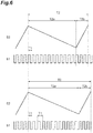
FIG. 6 is a view illustrating a relationship between the first drive signal and the second drive signal in the scanning device illustrated inFIG. 1 . -
FIG. 7 is a view illustrating a relationship between a first drive signal and a second drive signal in a scanning device of a comparative example. -
FIG. 8 is a configuration diagram of a modification example of the MEMS mirror mechanism and the control unit. - Hereinafter, an embodiment of the present disclosure will be described in detail with reference to the accompanying drawings. Note that, the same reference numeral will be given to the same or corresponding portion in respective drawings, and redundant description will be omitted.
- As illustrated in
FIG. 1 , for example, ascanning display system 10 is a laser scanning projection display that is mounted on a vehicle, and displays (projects and displays) an image to awindshield 100 of the vehicle. Thescanning display system 10 includes ascanning device 1 and anoptical system 11. Theoptical system 11 includes a plurality ofplanar mirrors concave mirror 11c, and awindshield 100. Thewindshield 100 functions as an optical element on a rearmost stage in theoptical system 11. Light L2 for projection display which is emitted from thescanning device 1 is sequentially reflected by theplanar mirror 11a, theplanar mirror 11b, theconcave mirror 11c, and thewindshield 100, and is incident to an eye E of an observer. - The
scanning device 1 includes alight source 2, aMEMS mirror mechanism 3, alight diffusion unit 4, and acontrol unit 5. Thelight source 2 emits laser light L1 for projection display. More specifically, thelight source 2 includes a plurality oflight emission units 2a. For example, the plurality oflight emission units 2a are a red laser diode, a green laser diode, and a blue laser diode, respectively. Thelight emission units 2a emits the laser light L1 having a wavelength in a visible region. The laser light L1 emitted from thelight emission units 2a is reflected by a plurality ofmirrors 2b including a dichroic mirror, proceeds on the same light path, and is incident to theMEMS mirror mechanism 3. - The
MEMS mirror mechanism 3 includes amirror 3a that reflects the laser light L1 emitted from thelight source 2. TheMEMS mirror mechanism 3 is a drive mirror manufactured by a MEMS (micro electro mechanical systems) technology, and a drive type of theMEMS mirror mechanism 3 is an electromagnetic drive type (details thereof will be described later). TheMEMS mirror mechanism 3 scans thelight diffusion unit 4 with the laser light L1 by swinging themirror 3a with respect to a first axial line and a second axial line which are orthogonal to each other as a central line. - The
light diffusion unit 4 diffuses the laser light L1 in the scanning by theMEMS mirror mechanism 3. For example, thelight diffusion unit 4 is a transmission-type microlens array, and allows the laser light L1 in the scanning by theMEMS mirror mechanism 3 to be transmitted and diffuses the laser light L1. In the laser light L1 diffused by thelight diffusion unit 4, light constituting an image is incident to theoptical system 11 disposed on a rear stage of thelight diffusion unit 4 as light L2 for projection display. - The
control unit 5 controls thelight source 2 and theMEMS mirror mechanism 3. As an example, when receiving an input signal indicating initiation of projection display, thecontrol unit 5 initiates output of thelight emission units 2a of thelight source 2. According to this, the laser light L1 is emitted from thelight source 2. At substantially the same time, thecontrol unit 5 initiates an operation of theMEMS mirror mechanism 3. According to this, in theMEMS mirror mechanism 3, swinging of themirror 3a is initiated, and thelight diffusion unit 4 is scanned with the laser light L1 emitted from thelight source 2. At this time, thecontrol unit 5 changes a ratio of the laser light L1 emitted from each of the respectivelight emission units 2a in correspondence with a scanning position of the laser light L1 (a position of an irradiation region with the laser light L1) in thelight diffusion unit 4. According to this, light L2 for projection display (that is, light constituting an image in the laser light L1 diffused by the light diffusion unit 4) is sequentially reflected by theplanar mirror 11a, theplanar mirror 11b, theconcave mirror 11c, and thewindshield 100, and is incident to the eye E of the observer. - As illustrated in
FIG. 2 , theMEMS mirror mechanism 3 includes a firstmovable unit 31, a secondmovable unit 32, asupport unit 33, afirst drive coil 34, a second drive coil (drive coil) 35, and amagnet 37 in addition to themirror 3a. Themirror 3a is provided in the firstmovable unit 31. The secondmovable unit 32 supports the firstmovable unit 31 to be swingable with respect to a first axial line A1 as a central line. Thesupport unit 33 supports the secondmovable unit 32 to be swingable with respect to a second axial line A2 that intersects (here, that is orthogonal to) the first axial line A1 as a central line. - More specifically, the second
movable unit 32 is formed in a frame shape to surround the firstmovable unit 31, and is connected to the firstmovable unit 31 through a pair oftorsion bars 38 disposed on the first axial line A1. Thesupport unit 33 is formed in a frame shape to surround the secondmovable unit 32, and is connected to the secondmovable unit 32 through a pair oftorsion bars 39 disposed on the second axial line A2. The firstmovable unit 31, the secondmovable unit 32, thesupport unit 33, the pair oftorsion bars 38, and the pair oftorsion bars 39 are integrally formed, for example, by an SOI (silicon on insulator) substrate. - The
first drive coil 34 is provided in the firstmovable unit 31. A first drive signal S1 for swinging themirror 3a with respect to the first axial line A1 as a central line is input to thefirst drive coil 34 from thecontrol unit 5, and an electromotive force signal S3 is output to thecontrol unit 5 from thefirst drive coil 34. Thesecond drive coil 35 is provided in the secondmovable unit 32. A second drive signal S2 for swinging themirror 3a with respect to the second axial line A2 as a central line is input to thesecond drive coil 35 from thecontrol unit 5. Themagnet 37 generates a magnetic field acting on thefirst drive coil 34 and thesecond drive coil 35. - The first drive signal S1 is an electric signal that resonates the
mirror 3a with respect to the first axial line A1 as a central line. When the first drive signal S1 is input to thefirst drive coil 34, a Lorenz force acts on thefirst drive coil 34 due to a mutual operation with the magnetic field generated by themagnet 37. In addition to the Lorenz force, when using resonance of themirror 3a and the firstmovable unit 31 in a natural frequency, it is possible to resonate themirror 3a with respect to the first axial line A1 as a central line. Note that, the natural frequency is determined by a mass of themirror 3a and the firstmovable unit 31, a spring constant of the pair oftorsion bars 38, and the like. - The second drive signal S2 is an electric signal for linearly operating the
mirror 3a with respect to the second axial line A2 as a central line. When the second drive signal S2 is input to thesecond drive coil 35, a Lorenz force acts on thesecond drive coil 35 due to a mutual operation with the magnetic field that is generated by themagnet 37. It is possible to linearly operate themirror 3a with respect to the second axial line A2 as a central line by using balance between the Lorenz force and an elastic force of the pair of torsion bars 39. - The electromotive force signal S3 is an electric signal for acquiring information relating to a vibration angle of the
mirror 3a or the like. When the firstmovable unit 31 is swung in the magnetic field generated by themagnet 37, an electromotive force is generated in thefirst drive coil 34 provided in the firstmovable unit 31. The electromotive force corresponds to the electromotive force signal S3. - As illustrated in
FIG. 2 andFIG. 3 , theMEMS mirror mechanism 3 reciprocate an irradiation region of the laser light L in a horizontal direction (first direction) D1 by swinging themirror 3a with respect to the first axial line A1 as a central line, and reciprocate the irradiation region of the laser light L in a vertical direction (second direction that intersects the first direction) D2 by swinging themirror 3a with respect to the second axial line A2 as a central line. Thecontrol unit 5 generates the first drive signal S1 and the second drive signal S2 so that an image of one frame is formed by m times of reciprocation (m: an integer of two or greater) of the irradiation region of the laser light L1 in the horizontal direction D1 and one time of reciprocation of the irradiation region of the laser light L1 in the vertical direction D2. - Note that,
FIG. 3 is a view illustrating a scanning trajectory of the laser light L1 on a primary image plane (here, a predetermined region in the light diffusion unit 4). InFIG. 3 , a solid-line trajectory represents the scanning trajectory of the laser light L1 emitted from thelight source 2. A broken-line trajectory represents a scanning trajectory of the laser light L1 in a case where the laser light L1 is not actually emitted from thelight source 2, but the laser light L1 is assumed to be emitted. That is, in thescanning device 1, an image is formed by performing scanning with the laser light L1 so that a drawing period (lighting-on period: a period in which thecontrol unit 5 causes thelight source 2 to emit the laser light L1) and a returning period (lighting-off period: a period in which thecontrol unit 5 does not cause thelight source 2 to emit the laser light L1) are provided (details will be described later). - As illustrated in
FIG. 4 , the first drive signal S1 is a rectangular wave in which one swing of themirror 3a with respect to the first axial line A1 as a central line is set as one cycle T1. The second drive signal S2 is a triangular wave in which one swing of themirror 3a with respect to the second axial line A2 as a central line is set as one cycle T2. In the second drive signal S2, in the one swing of themirror 3a with respect to the second axial line A2 as a central line, an outgoing period T2a in which themirror 3a rotates in one direction is longer than an incoming period T2b in which themirror 3a rotates in a direction opposite to the one direction. - The outgoing period T2a of the second drive signal S2 corresponds to a period obtained by accumulating the one cycle T1 of the first drive signal S1 n times (n: an integer of two or greater). The laser light L1 is emitted from the
light source 2 during the outgoing period T2a. That is, the outgoing period T2a is a drawing period in which the laser light L1 is emitted from thelight source 2. The incoming period T2b of the second drive signal S2 corresponds to a period obtained by accumulating the one cycle T1 of the first drive signal S1 m-n times (m-n: an integer of one or greater and smaller than n (here, an integer of two or greater and smaller than n)). The laser light L is not emitted from thelight source 2 during the incoming period T2b. That is, the incoming period T2b is a returning period for which the laser light L1 is not emitted from thelight source 2. Note that, the scanning trajectory of the laser light L1 as illustrated inFIG. 3 is an example of a case where a relationship between the first drive signal S1 and the second drive signal S2 as illustrated inFIG. 4 is further simplified. - As illustrated in
FIG. 2 , thecontrol unit 5 includes a PLL (phase locked loop)circuit 51. ThePLL circuit 51 includes aphase comparator 51a, aloop filter 51b, and a VCO (voltage controlled oscillator) 51c. The electromotive force signal S3 superimposed on the first drive signal S1 is input to thephase comparator 51a from thefirst drive coil 34. Thephase comparator 51a changes a voltage in correspondence with a variation of a phase of the electromotive force signal S3, and outputs a signal in which a voltage is changed. Theloop filter 51b removes a high-frequency component from the signal in which the voltage is changed by thephase comparator 51a, and outputs the signal from which the high-frequency component is removed. TheVCO 51c changes a frequency in correspondence with a variation of a voltage in the signal from which the high-frequency component is removed by theloop filter 51b, and outputs the signal in which the frequency is changed. - The
control unit 5 further includes afrequency divider 52, a D/A converter 53, and constantcurrent circuits frequency divider 52 divides a frequency of the signal in which the frequency is changed by theVCO 51c, and inputs the frequency-divided signal to thefirst drive coil 34 as the first drive signal S1. At this time, the first drive signal S1 is converted into a current by the constantcurrent circuit 57. The D/A converter 53 generates the second drive signal S2 on the basis of the signal in which the frequency is divided by thefrequency divider 52, and inputs the generated second drive signal S2 to thesecond drive coil 35. At this time, the second drive signal S2 is converted into a current by the constantcurrent circuit 58. In theMEMS mirror mechanism 3, a resonance frequency of themirror 3a may vary due to a variation of an ambient temperature or the like. When the resonance frequency of themirror 3a varies, a phase of the electromotive force signal S3 varies. Accordingly, thecontrol unit 5 can modulate the frequency of the first drive signal S1 to conform to the resonance frequency of themirror 3a by operating thePLL circuit 51 and thefrequency divider 52 as described above. - The
control unit 5 further includes amemory 54, a timingsignal generation unit 55, and anLD driver 56. Thememory 54 stores image information for projection display. The timingsignal generation unit 55 reads out image information corresponding to a scanning position of the laser light L1 on the basis of the signal in which the frequency is divided by thefrequency divider 52 from thememory 54, and transmits the read-out image information to theLD driver 56. TheLD driver 56 controls thelight source 2 so that the laser light L1 is modulated in correspondence with a scanning position of the laser light L1 (that is, so that a ratio of the laser light L1 emitted from each of thelight emission units 2a varies in correspondence with the scanning position of the laser light L1). - Generation of the first drive signal S1 and the second drive signal S2 by the
control unit 5 will be described in more detail. As illustrated inFIG. 5 , thecontrol unit 5 generates a second signal element S2i constituting the second drive signal S2 to correspond to a first signal element S1i in a current one cycle T1 in the first drive signal S1. More specifically, thecontrol unit 5 generates the second signal element S2i constituting the second drive signal S2 corresponding to one cycle T1 to correspond to the first signal element S1i of 1/2 cycle in the current one cycle T1 in the first drive signal S1. Here, thecontrol unit 5 sets the period of the first signal element S1i to be a period conforming to the resonance frequency of themirror 3a on the basis of a variation of the phase of the electromotive force signal S3 with respect to the first signal element S1i. According to this, thecontrol unit 5 sets a period of the second signal element S2i to correspond to the first signal element S1i, and sets a voltage value of the second signal element S2i. - The
control unit 5 may generate the second signal element S2i constituting the second drive signal S2 to correspond to a first signal element S1i-1 in an immediately previous one cycle T1 (one cycle T1 before the current one cycle T1 by one cycle) in the first drive signal S1. More specifically, thecontrol unit 5 generates the first signal element S1i of 1/2 cycle in the current one cycle T1 in the first drive signal S1 corresponding to one cycle T1 on the basis of the first signal element S1i-1 of 1/2 cycle in the immediately previous one cycle T1 (may be the first signal element S1i-1 of the first-half 1/2 cycle in the immediately previous one cycle T1, or may be the first signal element S1i-1 of the second-half 1/2 cycle in the immediately previous one cycle T1) in the first drive signal S1. Here, thecontrol unit 5 sets the period of the first signal element S1i to be a period conforming to the resonance frequency of themirror 3a on the basis of a variation of a phase of the electromotive force signal S3 with respect to the first signal element S1i-1. According to this, thecontrol unit 5 generates the second signal element S2i constituting the second drive signal S2 corresponding to one cycle T1 to correspond to the first signal element S1i. Here, thecontrol unit 5 sets a period of the second signal element S2i to be the same period as in the first signal element S1i, and sets a voltage value of the second signal element S2i. - Note that, the
control unit 5 generates the second signal element S2i to correspond to the first signal element S1i or S1i-1 in a 1/2 cycle period in the first drive signal S1, but may generate the second signal element S2i to correspond to the first signal element S1i or S1i-1 in an one cycle period in the first drive signal S1. Thecontrol unit 5 can generate the second signal element S2i to correspond to the first signal element S1i or S1i-1 in a period equal to or less than one cycle in the firstdrive signal S 1. - The
control unit 5 repeats generation of the first signal element S1i and generation of the second signal element S2i as described above in both the drawing period and the returning period while controlling the light source 2 (refer toFIG. 4 ) so that the outgoing period T2a corresponds to the drawing period and the incoming period T2b corresponds to the returning period. According to this, in a case where the period of the first signal element S1i is constant as illustrated inFIG. 6(a) , and in a case where the period of the first signal element S1i varies in one frame due to a variation of the resonance frequency of themirror 3a as illustrated inFIG. 6(b) , a deviation does not occur in the corresponding relationship between the first drive signal S1 and the second drive signal S2. As described above, thecontrol unit 5 repeats generation of the first signal element S1i and the second signal element S2i while fluctuating a frame rate (the number of frames processed per unit time). - If generation of the first signal element S1i and generation of the second signal element S2i are not repeated in both the drawing period and the returning period, in a case where the period of the first signal element S1i is constant as illustrated in
FIG. 7(a) , a deviation does not occur in the corresponding relationship between the first drive signal S1 and the second drive signal S2, but in a case where the period of the first signal element S1i varies in one frame due to the variation of the resonance frequency of themirror 3a as illustrated inFIG. 7(b) , a deviation occurs in the corresponding relationship between the first drive signal S1 and the second drive signal S2. - In the
scanning device 1, the first drive signal S1 and the second drive signal S2 are generated so that m times of reciprocation (m: an integer of two or greater) of the irradiation region of the laser light L1 in the horizontal direction and one time of reciprocation of the irradiation region of the laser light L1 in the vertical direction correspond to each other. More specifically, the second signal element S2i constituting the second drive signal S2 is generated to correspond to the first signal element S1i in a period equal to or less than one cycle period in the first drive signal S1. In addition, generation of the second signal element S2i is repeated in both the outgoing period T2a and the incoming period T2b in the one swing of themirror 3a with respect to the second axial line A2 as a central line. According to this, even though theMEMS mirror mechanism 3 is influenced by a variation of an ambient temperature or the like, it is possible to suppress occurrence of a deviation in the corresponding relationship between the first drive signal S1 and the second drive signal S2. Accordingly, according to thescanning device 1, stable scanning with the laser light L1, and further, stable image display (for example, image display in which occurrence of a flicker phenomenon that occurs in a case as illustrated inFIG. 7(b) is suppressed) become possible. - As described above, in a case where the
control unit 5 generates the second signal element S2i to correspond to the first signal element S1i or S1i-1 in a 1/2 cycle period in the first drive signal S1, or in a case where thecontrol unit 5 generates the second signal element S2i to correspond to the first signal element S1i or S1i-1 in an one cycle period in the first drive signal S1, it is possible to make a process when generating the second signal element S2i easy. In addition, in a case where thecontrol unit 5 generates the second signal element S2i to correspond to the first signal element S1i in a current one cycle T1 in the first drive signal S1, or in a case where thecontrol unit 5 generates the second signal element S2i to correspond to the first signal element S1i-1 in an immediately previous one cycle T1 in the first drive signal S1, time delay when generating the second signal element S2i can be minimized. In addition, in a case where thecontrol unit 5 generates the second signal element S2i to correspond to the first signal element S1i in the current one cycle T1 in the first drive signal S1, even when the resonance frequency of themirror 3a varies in the middle of the first signal element S1i and the period of the first signal element S1i is shortened, it is possible to make the period of the second signal element S2i match the period of the first signal element S1i by determining the period of the second signal element S2i with reference to the electromotive force signal S3 corresponding to the first signal element S1i. - In the
scanning device 1, the first drive signal S1 is an electric signal for resonating themirror 3a with respect to the first axial line A1 as a central line, the second drive signal S2 is an electric signal for linearly operating themirror 3a with respect to the second axial line A2 as a central line, and thecontrol unit 5 modulates the frequency of the first drive signal S1 to conform to the resonance frequency of themirror 3a. According to this, even when the resonance frequency of themirror 3a varies due to a variation of an ambient temperature or the like, it is possible to more reliably suppress occurrence of a deviation in the corresponding relationship between the first drive signal S1 and the second drive signal S2. Particularly, in thecontrol unit 5, since thePLL circuit 51 is used, it is not necessary to separately provide a configuration for measuring the resonance frequency of themirror 3a, and thus it is possible to realize reduction in size of the device and simplification of a configuration of the device. - In the
scanning device 1, thecontrol unit 5 controls thelight source 2 so that the outgoing period T2a corresponds to the drawing period and the incoming period T2b corresponds to the returning period, and repeats generation of the second signal element S2i in both the drawing period and the returning period. In a case where the returning period is provided in the scanning with the laser light L1, since a temperature of theMEMS mirror mechanism 3 is lowered in the returning period in which themirror 3a is not irradiated with the laser light L1, the resonance frequency of themirror 3a is likely to fluctuate. Accordingly, in a case where the returning period is provided in the scanning with the laser light L1, repeating generation of the second signal element S2i as described above is particularly effective for suppressing occurrence of a deviation in the corresponding relationship between the first drive signal S1 and the second drive signal S2 in each drawing period. That is, since the first drive signal S1 and the second drive signal S2 correspond to each other even in the returning period, it is not necessary to adjust the deviation between the first drive signal S1 and the second drive signal S2 at the time of initiating the subsequent drawing period. In addition, when stopping the resonance operation of themirror 3a in the returning period, it is difficult to promptly swing themirror 3a at a high speed at the time of initiating the subsequent drawing period, and as a result, an image is blurred at the time of initiating the subsequent drawing period. In thescanning device 1, since the resonance operation of themirror 3a is not stopped by providing the first drive signal S1 corresponding to a plurality of cycles in the returning period, the resonance operation of themirror 3a becomes stable at the time of initiating the subsequent drawing period, and an image is not blurred at the time of initiating the subsequent drawing period. - In the
scanning device 1, the electromagnetic drive typeMEMS mirror mechanism 3 is used. In the electromagnetic drive typeMEMS mirror mechanism 3, the resonance frequency of themirror 3a is likely to vary due to a variation of a spring constant of the pair oftorsion bars 38 due to a variation of an ambient temperature, a variation of a moment of inertia due to attachment of particles or the like, a variation of an attenuation coefficient of the pair oftorsion bars 38 due to a variation of an atmospheric pressure, a variation of the spring constant of the pair oftorsion bars 38 due to an operation of the secondmovable unit 32 with respect to the second axial line A2 as a central line, a variation of the spring constant and the attenuation coefficient of the pair oftorsion bars 38 due to an aging variation of metal wires provided in the pair oftorsion bars 38, or the like. The size of theMEMS mirror mechanism 3 is small, and thus fluctuation of the resonance frequency of themirror 3a is more significant in comparison to a large-sized mirror mechanism such as a galvano mirror. Accordingly, in a case where the electromagnetic drive typeMEMS mirror mechanism 3 is used, repeating generation of the second signal element S2i as described above is particularly effective for suppressing occurrence of a deviation in the corresponding relationship between the first drive signal S1 and the second drive signal S2 in each drawing period. - In the
scanning device 1, thecontrol unit 5 controls thelight source 2 so that the laser light L1 is modulated in correspondence with a scanning position of the laser light L1. According to this, image display with higher quality is possible. Note that, when an absorption rate of the laser light L1 in themirror 3a fluctuates due to modulation of the laser light L1, the resonance frequency of themirror 3a fluctuates. Accordingly, in this case, repeating generating of the second signal element S2i as described above is particularly effective for suppressing occurrence of a deviation in the corresponding relationship between the first drive signal S1 and the second drive signal S2 in each drawing period. - In the
scanning device 1, thecontrol unit 5 repeats generation of the second signal element S2i while fluctuating the frame rate. According to this, it is possible to easily and reliably repeat generation of the second signal element S2i. This is a finding found independently from a finding in the related art in which the frame rate is typically fixed, and enables stable image display. - The present disclosure is not limited to the one embodiment. For example, the
light source 2 is not limited to a light source that uses a laser diode (semiconductor laser), and may be a light source that uses a surface-emitting laser, an SLD (super luminescent diode), or the like. In addition, a drive type of theMEMS mirror mechanism 3 is not limited to the electromagnetic drive type, and may be an electrostatic drive type, a piezoelectric drive type, a thermal drive type, or the like. In addition, thelight diffusion unit 4 is not limited to the transmission type microlens array, and may be reflection type microlens array, a micro mirror array, a diffraction lattice, a fiber optic plate, or the like. - In addition, as illustrated in
FIG. 8 , theMEMS mirror mechanism 3 may further include an electromotiveforce monitoring coil 36. The electromotiveforce monitoring coil 36 is provided in the firstmovable unit 31 to be located on an inner side of thefirst drive coil 34. The electromotive force signal S3 is output to the control unit 5 (more specifically, thephase comparator 51a of the PLL circuit 51) from the electromotiveforce monitoring coil 36. When the firstmovable unit 31 is swung in the magnetic field generated by themagnet 37, an electromotive force is generated in the electromotiveforce monitoring coil 36 provided in the firstmovable unit 31. The electromotive force corresponds to the electromotive force signal S3. Even in this case, generation of any of the second signal element S2i is possible. - However, in the case of acquiring the electromotive force generated in the
first drive coil 34 as the electromotive force signal S3, the following advantage is attained. That is, thefirst drive coil 34 is wound along an outer edge of the firstmovable unit 31 to swing the firstmovable unit 31 with high efficiency. In this case, a winding diameter of thefirst drive coil 34 increases, and thus a large electromotive force can be obtained even in a small number of turns. In addition, only a wire electrically connected to thefirst drive coil 34 passes through the torsion bars 38, and thus manufacturing of theMEMS mirror mechanism 3 can become easy. - In the
MEMS mirror mechanism 3 illustrated inFIG. 2 andFIG. 8 , thefirst drive coil 34 for swinging the firstmovable unit 31 is provided in the firstmovable unit 31 and thesecond drive coil 35 for swinging the secondmovable unit 32 is provided in the secondmovable unit 32, but theMEMS mirror mechanism 3 may be configured as follows. As anMEMS mirror mechanism 3 of a first modification example, a drive coil for swinging the firstmovable unit 31 and a drive coil for swinging the secondmovable unit 32 may be provided in the secondmovable unit 32. Alternatively, as anMEMS mirror mechanism 3 of a second modification example, a single drive coil for swinging the firstmovable unit 31 and the secondmovable unit 32 may be provided in the secondmovable unit 32. - In the
MEMS mirror mechanism 3 of the first modification example and theMEMS mirror mechanism 3 of the second modification example, the electromotive force monitoring coil may be provided in the firstmovable unit 31, and in this case, the electromotive force signal S3 corresponding to an electromotive force corresponding to swinging of the firstmovable unit 31 may be output to thecontrol unit 5 from the electromotive force monitoring coil. Alternatively, in theMEMS mirror mechanism 3 of the first modification example and theMEMS mirror mechanism 3 of the second modification example, the electromotive force monitoring coil may be provided in the secondmovable unit 32, and in this case, the electromotive force signal S3 corresponding to an electromotive force corresponding to swinging of the firstmovable unit 31 may be output to thecontrol unit 5 from the electromotive force monitoring coil. In theMEMS mirror mechanism 3 of the first modification example and theMEMS mirror mechanism 3 of the second modification example, since the secondmovable unit 32 is vibrated by the drive coil provided in the secondmovable unit 32, and the vibration is transmitted to the firstmovable unit 31 to swing the firstmovable unit 31, even in a case where the electromotive force monitoring coil is provided in the secondmovable unit 32, it is possible to measure an electromotive force corresponding to the swinging of the firstmovable unit 31. Alternatively, in theMEMS mirror mechanism 3 of the first modification example and theMEMS mirror mechanism 3 of the second modification example, the electromotive force signal S3 corresponding to an electromotive force generated in the drive coil (that is, the drive coil provided in the second movable unit 32) in correspondence with swinging of the firstmovable unit 31 may be output to thecontrol unit 5 from the drive coil. - In addition, the
control unit 5 may control thelight source 2 so that the outgoing period T2a corresponds to a first drawing period (a first lighting-on period: a period in which thecontrol unit 5 causes thelight source 2 to emit the laser light L1), and the incoming period T2b corresponds to a second drawing period (a second lighting-on period: a period in which thecontrol unit 5 causes thelight source 2 to emit the laser light L1), and may repeat generation of the second signal element S2i in both the first drawing period and the second drawing period. According to this configuration, in the first drawing period and the second drawing period, it is possible to suppress occurrence of a deviation in the corresponding relationship between the first drive signal S1 and the second drive signal S2. Note that, in this case, an image of two frames is formed by m times of reciprocation (m: an integer of two or greater) of an irradiation region of the laser light L1 in the horizontal direction, and one time of reciprocation of the irradiation region of the laser light L1 in a vertical direction. In addition, the second drive signal S2 in this case, for example, is a triangular wave in which the outgoing period T2a and the incoming period T2b are mutually equal to each other. - In addition, the first drive signal S1 may be a sinusoidal wave or the like without limitation to the rectangular wave as long as the first drive signal S1 is an electric signal in which one swing of the
mirror 3a with respect to the first axial line A1 as a central line is set as one cycle T1. In addition, the second drive signal S2 may be a sinusoidal wave or the like without limitation to the triangular wave as long as the second drive signal S2 is an electric signal in which one swing of themirror 3a with respect to the second axial line A2 as a central line is set as one cycle T2. In addition, in the second signal element S2i of the second drive signal S2, the voltage value may not be constant, and may increase or decrease. - In addition, a circuit that modulates the frequency of the first drive signal S1 to conform to the resonance frequency of the
mirror 3a may be a DDS (direct digital synthesizer) circuit or the like without limitation to thePLL circuit 51. - The
control unit 5 may generate not only the first drive signal S1 in which a period varies from the first signal element S1i in which a period varies, but also the first drive signal S1 in which a period is constant from the first signal element S1i in which a period is constant. Even when thecontrol unit 5 generates the first drive signal S1 in which the period is constant from the first signal element S1i in which the period is constant, a period of the first drive signal S1 input to theMEMS mirror mechanism 3 may vary due to a variation of the resonance frequency of themirror 3a. Even in this case, according to thescanning device 1, the first drive signal S1 and the second drive signal S2 are generated so that m times of reciprocation of the irradiation region of the laser light L1 in the horizontal direction and one time of reciprocation of the irradiation region of the laser light L1 in the vertical direction correspond to each other. - In addition, the
scanning device 1 may be used in various aspects such as a helmet-embedded type, an eyeglass type without limitation to the vehicle-mounted type. In addition, the scanning device of the present disclosure can be used in a distance image sensor. In the distance image sensor, a distance measurement region is scanned with laser light emitted from a scanning device, and laser light reflected from the distance measurement region is detected by a light detector. In the distance image sensor, a distance is measured with respect to respective sites in the distance measurement region that is scanned with the laser light on the basis of time until the laser light is detected with the light detector after the laser light is pulse-oscillated from a light source of the scanning device. A control unit of the scanning device which is used in the distance image sensor generates a first drive signal and a second drive signal so that m times of reciprocation (m: an integer of two or greater) of an irradiation region of the laser light in the first direction and one time of reciprocation of the irradiation region of the laser light in the second direction correspond to each other. - 1: scanning device, 2: light source, 3: MEMS mirror mechanism, 3a: mirror, 5: control unit, 31: first movable unit, 32: second movable unit, 33: support unit, 34: first drive coil, 35: second drive coil (drive coil), 36: electromotive force monitoring coil, 37: magnet, A1: first axial line, A2: second axial line, D1: horizontal direction (first direction), D2: vertical direction (second direction), L1: laser light.
Claims (12)
- A scanning device comprising:a light source configured to emit laser light;an MEMS mirror mechanism including a mirror configured to reflect the laser light emitted from the light source, the MEMS mirror mechanism being configured to reciprocate an irradiation region of the laser light in a first direction by swinging the mirror with respect to a first axial line as a central line, and reciprocate the irradiation region in a second direction that intersects the first direction by swinging the mirror with respect to a second axial line as a central line that intersects the first axial line; anda control unit configured to generate a first drive signal for swinging the mirror with respect to the first axial line as a central line and a second drive signal for swinging the mirror with respect to the second axial line as a central line, and input the first drive signal and the second drive signal to the MEMS mirror mechanism,wherein the first drive signal is an electric signal in which one swing of the mirror with respect to the first axial line as a central line is set as one cycle,the second drive signal is an electric signal in which one swing of the mirror with respect to the second axial line as a central line is set as one cycle, andthe control unit is configured to generate a second signal element constituting the second drive signal to correspond to a first signal element in a period equal to or less than one cycle period in the first drive signal, and repeats generation of the second signal element in both an outgoing period and an incoming period in the one swing of the mirror with respect to the second axial line as a central line to generate the first drive signal and the second drive signal so that m times of reciprocation (m: an integer of two or greater) of the irradiation region in the first direction and one time of reciprocation of the irradiation region in the second direction correspond to each other.
- The scanning device according to claim 1,
wherein the first drive signal is an electric signal for resonating the mirror with respect to the first axial line as a central line,
the second drive signal is an electric signal for linearly operating the mirror with respect to the second axial line as a central line, and
the control unit modulates a frequency of the first drive signal to conform to a resonance frequency of the mirror. - The scanning device according to claim 1 or 2,
wherein the control unit is configured to control the light source so that the outgoing period corresponds to a lighting-on period and the incoming period corresponds to a lighting-off period, and repeats generation of the second signal element in both the lighting-on period and the lighting-off period. - The scanning device according to claim 1 or 2,
wherein the control unit is configured to control the light source so that the outgoing period corresponds to a first lighting-on period and the incoming period corresponds to a second lighting-on period, and repeats generation of the second signal element in both the first lighting-on period and the second lighting-on period. - The scanning device according to any one of claims 1 to 4,
wherein the control unit is configured to generate the second signal element to correspond to the first signal element in a 1/2 cycle period in the first drive signal. - The scanning device according to any one of claims 1 to 4,
wherein the control unit is configured to generate the second signal element to correspond to the first signal element in an one cycle period in the first drive signal. - The scanning device according to any one of claims 1 to 6,
wherein the control unit is configured to generate the second signal element to correspond to the first signal element in a current one cycle period in the first drive signal. - The scanning device according to any one of claims 1 to 6,
wherein the control unit is configured to generate the second signal element to correspond to the first signal element in an immediately previous one cycle period in the first drive signal. - The scanning device according to any one of claims 1 to 8,
wherein the MEMS mirror mechanism includes:a first movable unit provided with the mirror;a second movable unit configured to support the first movable unit to be swingable with respect to the first axial line as a central line;a support unit configured to support the second movable unit to be swingable with respect to the second axial line as a central line;a drive coil that is provided in the second movable unit; anda magnet configured to generate a magnetic field acting on the drive coil. - The scanning device according to any one of claims 1 to 9,
wherein the light source is configured to emit the laser light for projection display, and
the control unit is configured to generate the first drive signal and the second drive signal so that an image of one frame or two frames is formed by the m times of reciprocation of the irradiation region in the first direction and the one time of reciprocation of the irradiation region in the second direction. - The scanning device according to claim 10,
wherein the control unit is configured to control the light source so that the laser light is modulated in correspondence with a position of the irradiation region. - The scanning device according to claim 10 or 11,
wherein the control unit is configured to repeat generation of the second signal element while fluctuating a frame rate.
Applications Claiming Priority (2)
| Application Number | Priority Date | Filing Date | Title |
|---|---|---|---|
| JP2017143599 | 2017-07-25 | ||
| PCT/JP2018/027518 WO2019022014A1 (en) | 2017-07-25 | 2018-07-23 | Scanning device |
Publications (2)
| Publication Number | Publication Date |
|---|---|
| EP3660574A1 true EP3660574A1 (en) | 2020-06-03 |
| EP3660574A4 EP3660574A4 (en) | 2021-04-28 |
Family
ID=65040575
Family Applications (1)
| Application Number | Title | Priority Date | Filing Date |
|---|---|---|---|
| EP18838227.9A Pending EP3660574A4 (en) | 2017-07-25 | 2018-07-23 | SCAN DEVICE |
Country Status (6)
| Country | Link |
|---|---|
| US (2) | US11294169B2 (en) |
| EP (1) | EP3660574A4 (en) |
| JP (2) | JP6528015B1 (en) |
| CN (2) | CN110945404B (en) |
| TW (2) | TWI827325B (en) |
| WO (1) | WO2019022014A1 (en) |
Cited By (1)
| Publication number | Priority date | Publication date | Assignee | Title |
|---|---|---|---|---|
| WO2021140160A1 (en) | 2020-01-07 | 2021-07-15 | Elmos Semiconductor Se | Light module and lidar apparatus having at least one light module of this type |
Families Citing this family (4)
| Publication number | Priority date | Publication date | Assignee | Title |
|---|---|---|---|---|
| CN110945404B (en) * | 2017-07-25 | 2022-07-15 | 浜松光子学株式会社 | Scanning device |
| TWI806993B (en) * | 2019-03-20 | 2023-07-01 | 揚明光學股份有限公司 | Light path adjustment mechanism and fabrication method thereof |
| CN113176550B (en) * | 2019-12-30 | 2023-04-07 | 上海禾赛科技有限公司 | Frame synchronization method for scanning galvanometer and laser radar |
| DE102023111340A1 (en) | 2023-05-02 | 2024-11-07 | OQmented GmbH | synchronous drive for MEMS |
Family Cites Families (27)
| Publication number | Priority date | Publication date | Assignee | Title |
|---|---|---|---|---|
| US6049407A (en) * | 1997-05-05 | 2000-04-11 | University Of Washington | Piezoelectric scanner |
| US5937297A (en) * | 1998-06-01 | 1999-08-10 | Chartered Semiconductor Manufacturing, Ltd. | Method for making sub-quarter-micron MOSFET |
| US7031040B2 (en) * | 2003-05-16 | 2006-04-18 | Ricoh Company, Ltd. | Optical scanning apparatus, optical writing apparatus, image forming apparatus, and method of driving vibration mirror |
| US7675669B2 (en) * | 2004-09-27 | 2010-03-09 | Qualcomm Mems Technologies, Inc. | Method and system for driving interferometric modulators |
| JP4857582B2 (en) | 2005-03-30 | 2012-01-18 | ブラザー工業株式会社 | Optical scanning device and optical scanning device control method |
| JP2009198988A (en) * | 2008-02-25 | 2009-09-03 | Funai Electric Co Ltd | Image display device |
| US8373690B2 (en) * | 2008-10-17 | 2013-02-12 | Panasonic Corporation | Scanning image display apparatus |
| JP2010197718A (en) * | 2009-02-25 | 2010-09-09 | Olympus Corp | Driving module |
| JP5446450B2 (en) * | 2009-05-20 | 2014-03-19 | 船井電機株式会社 | Laser projector |
| US8643923B2 (en) * | 2009-11-25 | 2014-02-04 | Nec Corporation | Optical scanning device, optical scanning method, program, and image display device |
| JP5402589B2 (en) * | 2009-12-04 | 2014-01-29 | セイコーエプソン株式会社 | Optical scanning device |
| CN101806621B (en) * | 2010-02-26 | 2011-07-20 | 江苏惠通集团有限责任公司 | Motion compensation system and method of MEMS spectrometer |
| US8576468B2 (en) * | 2010-09-22 | 2013-11-05 | Microvision, Inc. | Scanning projector with dynamic scan angle |
| JP5906115B2 (en) | 2012-03-29 | 2016-04-20 | 川崎重工業株式会社 | Optical scanning apparatus and laser processing apparatus |
| JP5879175B2 (en) * | 2012-03-29 | 2016-03-08 | 京セラドキュメントソリューションズ株式会社 | Image forming apparatus |
| CN104603672B (en) * | 2012-03-30 | 2017-05-10 | 汤姆逊许可公司 | Laser projector system with graphical pointer |
| JP5950692B2 (en) * | 2012-05-25 | 2016-07-13 | 三菱電機株式会社 | Stereoscopic image display device |
| CN103869062A (en) * | 2012-12-18 | 2014-06-18 | 中国科学技术大学 | Micro-cantilever beam array biochemical sensing apparatus based on piezoelectric scanning and method |
| WO2014103803A1 (en) * | 2012-12-28 | 2014-07-03 | 株式会社Jvcケンウッド | Mems optical scanner |
| WO2014132447A1 (en) * | 2013-03-01 | 2014-09-04 | パイオニア株式会社 | Optical scanning device |
| CN104155755A (en) | 2013-05-13 | 2014-11-19 | 中强光电股份有限公司 | Laser light scanning device and control method thereof |
| CN104181761A (en) * | 2013-05-23 | 2014-12-03 | 鸿富锦精密工业(深圳)有限公司 | Miniature projection device |
| JP6059094B2 (en) * | 2013-06-25 | 2017-01-11 | 浜松ホトニクス株式会社 | Radiation image reading device |
| JP6533365B2 (en) * | 2014-03-13 | 2019-06-19 | 株式会社リコー | Light deflection device, light deflection mirror and image display device |
| TWI605013B (en) * | 2014-07-01 | 2017-11-11 | 村田製作所股份有限公司 | Micro-optical electromechanical scanning device and method for manufacturing it |
| JP6655377B2 (en) * | 2015-12-16 | 2020-02-26 | 株式会社東芝 | Optical scanning device and optical scanning method |
| CN110945404B (en) * | 2017-07-25 | 2022-07-15 | 浜松光子学株式会社 | Scanning device |
-
2018
- 2018-07-23 CN CN201880047747.9A patent/CN110945404B/en active Active
- 2018-07-23 CN CN202210741004.XA patent/CN114994906B/en active Active
- 2018-07-23 EP EP18838227.9A patent/EP3660574A4/en active Pending
- 2018-07-23 US US16/632,958 patent/US11294169B2/en active Active
- 2018-07-23 WO PCT/JP2018/027518 patent/WO2019022014A1/en not_active Ceased
- 2018-07-23 JP JP2019510715A patent/JP6528015B1/en active Active
- 2018-07-25 TW TW111140730A patent/TWI827325B/en active
- 2018-07-25 TW TW107125669A patent/TWI782063B/en active
-
2019
- 2019-05-13 JP JP2019090590A patent/JP6545414B1/en active Active
-
2022
- 2022-02-25 US US17/681,031 patent/US11644666B2/en active Active
Cited By (4)
| Publication number | Priority date | Publication date | Assignee | Title |
|---|---|---|---|---|
| WO2021140160A1 (en) | 2020-01-07 | 2021-07-15 | Elmos Semiconductor Se | Light module and lidar apparatus having at least one light module of this type |
| EP4239370A2 (en) | 2020-01-07 | 2023-09-06 | Elmos Semiconductor SE | Light module and lidar device comprising at least one such light module |
| EP4254011A2 (en) | 2020-01-07 | 2023-10-04 | Elmos Semiconductor SE | Light module and lidar apparatus having at least one light module of this type |
| US12394958B2 (en) | 2020-01-07 | 2025-08-19 | Elmos Semiconductor Se | Light module and LIDAR apparatus having at least one light module of this type |
Also Published As
| Publication number | Publication date |
|---|---|
| TWI827325B (en) | 2023-12-21 |
| US20200159008A1 (en) | 2020-05-21 |
| JP6528015B1 (en) | 2019-06-12 |
| US11294169B2 (en) | 2022-04-05 |
| TWI782063B (en) | 2022-11-01 |
| JP2019174818A (en) | 2019-10-10 |
| WO2019022014A1 (en) | 2019-01-31 |
| TW202309600A (en) | 2023-03-01 |
| TW201908806A (en) | 2019-03-01 |
| JPWO2019022014A1 (en) | 2019-07-25 |
| JP6545414B1 (en) | 2019-07-17 |
| US20220179198A1 (en) | 2022-06-09 |
| CN110945404B (en) | 2022-07-15 |
| CN110945404A (en) | 2020-03-31 |
| US11644666B2 (en) | 2023-05-09 |
| EP3660574A4 (en) | 2021-04-28 |
| CN114994906B (en) | 2024-03-08 |
| CN114994906A (en) | 2022-09-02 |
Similar Documents
| Publication | Publication Date | Title |
|---|---|---|
| US11644666B2 (en) | Scanning device | |
| JP6012276B2 (en) | Deflection device for a scanner performing Lissajous scanning | |
| US9182600B2 (en) | Image display apparatus and head-mounted display | |
| US20110043768A1 (en) | Image display apparatus | |
| JP5446450B2 (en) | Laser projector | |
| JP6513962B2 (en) | Optical scanner | |
| EP2646868A1 (en) | A method for projecting an image | |
| EP3223540A1 (en) | Optical microphone system | |
| US8270057B2 (en) | Oscillator device, optical deflecting device and method of controlling the same | |
| JP4929738B2 (en) | Optical scanning device, optical scanning device control method, and image display device | |
| WO2006106837A1 (en) | Optical scanner and method of controlling optical scanner | |
| JP5828323B2 (en) | Image projection apparatus and image projection method | |
| US11169371B2 (en) | Scanning device | |
| JP2011090030A (en) | Image display device | |
| US7059523B1 (en) | Scan line alignment in raster pattern | |
| JP2008089932A (en) | Optical scanning device, image display device including the same, retinal scanning image display device, and method of driving optical scanning element | |
| JP2011013277A (en) | Optical scanner, image display apparatus having optical scanner and driving method of optical scanner | |
| JP5516746B2 (en) | Micro scanner and optical apparatus equipped with the same | |
| US7582219B1 (en) | Method of fabricating reflective mirror by wet-etch using improved mask pattern and reflective mirror fabricated using the same | |
| CN115840284A (en) | Optical path control device and display device | |
| JP2023045004A (en) | Optical path controller and display device | |
| CN121969977A (en) | Optical scanning device and driving method thereof | |
| JP2023045201A (en) | Optical path controller and display device | |
| JP2023045200A (en) | Optical path control device and display device | |
| JP2017097141A (en) | Projector |
Legal Events
| Date | Code | Title | Description |
|---|---|---|---|
| STAA | Information on the status of an ep patent application or granted ep patent |
Free format text: STATUS: THE INTERNATIONAL PUBLICATION HAS BEEN MADE |
|
| PUAI | Public reference made under article 153(3) epc to a published international application that has entered the european phase |
Free format text: ORIGINAL CODE: 0009012 |
|
| STAA | Information on the status of an ep patent application or granted ep patent |
Free format text: STATUS: REQUEST FOR EXAMINATION WAS MADE |
|
| 17P | Request for examination filed |
Effective date: 20200127 |
|
| AK | Designated contracting states |
Kind code of ref document: A1 Designated state(s): AL AT BE BG CH CY CZ DE DK EE ES FI FR GB GR HR HU IE IS IT LI LT LU LV MC MK MT NL NO PL PT RO RS SE SI SK SM TR |
|
| AX | Request for extension of the european patent |
Extension state: BA ME |
|
| DAV | Request for validation of the european patent (deleted) | ||
| DAX | Request for extension of the european patent (deleted) | ||
| A4 | Supplementary search report drawn up and despatched |
Effective date: 20210326 |
|
| RIC1 | Information provided on ipc code assigned before grant |
Ipc: G02B 26/10 20060101AFI20210322BHEP Ipc: B81B 3/00 20060101ALI20210322BHEP Ipc: G02B 26/08 20060101ALI20210322BHEP |
|
| STAA | Information on the status of an ep patent application or granted ep patent |
Free format text: STATUS: EXAMINATION IS IN PROGRESS |
|
| 17Q | First examination report despatched |
Effective date: 20230412 |