EP3665924B1 - Quality of service implementations for separating user plane - Google Patents
Quality of service implementations for separating user plane Download PDFInfo
- Publication number
- EP3665924B1 EP3665924B1 EP17920745.1A EP17920745A EP3665924B1 EP 3665924 B1 EP3665924 B1 EP 3665924B1 EP 17920745 A EP17920745 A EP 17920745A EP 3665924 B1 EP3665924 B1 EP 3665924B1
- Authority
- EP
- European Patent Office
- Prior art keywords
- qos
- base station
- user plane
- quality
- data packet
- Prior art date
- Legal status (The legal status is an assumption and is not a legal conclusion. Google has not performed a legal analysis and makes no representation as to the accuracy of the status listed.)
- Active
Links
Images


Classifications
-
- H—ELECTRICITY
- H04—ELECTRIC COMMUNICATION TECHNIQUE
- H04W—WIRELESS COMMUNICATION NETWORKS
- H04W12/00—Security arrangements; Authentication; Protecting privacy or anonymity
- H04W12/06—Authentication
-
- H—ELECTRICITY
- H04—ELECTRIC COMMUNICATION TECHNIQUE
- H04W—WIRELESS COMMUNICATION NETWORKS
- H04W28/00—Network traffic management; Network resource management
- H04W28/02—Traffic management, e.g. flow control or congestion control
- H04W28/0252—Traffic management, e.g. flow control or congestion control per individual bearer or channel
- H04W28/0263—Traffic management, e.g. flow control or congestion control per individual bearer or channel involving mapping traffic to individual bearers or channels, e.g. traffic flow template [TFT]
-
- H—ELECTRICITY
- H04—ELECTRIC COMMUNICATION TECHNIQUE
- H04W—WIRELESS COMMUNICATION NETWORKS
- H04W28/00—Network traffic management; Network resource management
- H04W28/02—Traffic management, e.g. flow control or congestion control
- H04W28/0268—Traffic management, e.g. flow control or congestion control using specific QoS parameters for wireless networks, e.g. QoS class identifier [QCI] or guaranteed bit rate [GBR]
-
- H—ELECTRICITY
- H04—ELECTRIC COMMUNICATION TECHNIQUE
- H04W—WIRELESS COMMUNICATION NETWORKS
- H04W28/00—Network traffic management; Network resource management
- H04W28/02—Traffic management, e.g. flow control or congestion control
- H04W28/10—Flow control between communication endpoints
-
- H—ELECTRICITY
- H04—ELECTRIC COMMUNICATION TECHNIQUE
- H04W—WIRELESS COMMUNICATION NETWORKS
- H04W72/00—Local resource management
- H04W72/50—Allocation or scheduling criteria for wireless resources
- H04W72/54—Allocation or scheduling criteria for wireless resources based on quality criteria
- H04W72/543—Allocation or scheduling criteria for wireless resources based on quality criteria based on requested quality, e.g. QoS
Definitions
- This document relates to systems, devices and techniques for wireless communications.
- 3GPP R2-169070 relates to a summary of 3GPP SA2 decisions that impact RAN2 and relates to QoS signaling needed in RAN.
- 3GPP R2-166335 relates to RAN considerations on the impact of QoS on NR control plane.
- 3GPP R2-166336 relates to RAN considerations on the impact of QoS on NR control plane in the uplink.
- a data stream having the same QoS (Quality of Service) requirement is aggregated into a bearer, a radio access network (Radio Access Network, RAN) and the core network (Core Network, CN) on the QoS processing is carried by the load.
- the RAN includes an evolved Node B (eNB) and a User Equipment (UE).
- eNB evolved Node B
- UE User Equipment
- a 5G base station is sometimes called gNB (Next Generation Node B, next generation base station). Similar to the 4G system between the eNB X2 interface, the gNB interface on an interface called Xn. The interface between the gNB and the 5G core network is called the NG interface.
- gNB Next Generation Node B, next generation base station.
- Xn The interface between the gNB and the 5G core network is called the NG interface.
- a 5G system is expected to use a new QoS mechanism.
- the radio interface on the radio bearer may use a DRB (Data Radio Bearer, data radio bearer), but there is no corresponding NG interface on the network side, instead the concept of the PDU Session (Protocol Data Unit Session, Protocol Data Unit Session, and QoS Flow (Quality of Service Flow) is used.
- a UE can have multiple PDU sessions.
- a PDU session can contain multiple QoS flows. Multiple QoS flows of the same PDU session can be mapped to the same DRB. The QoS flow of different PDU sessions cannot be mapped to the same DRB.
- the new 5G QoS mechanism also introduced the NAS Reflective (Non-Access-Stratum Reflective) and AS Reflective (Access-Stratum Reflective) functions, mainly in order to save control overhead.
- the NAS Reflective is the user-facing way to complete the uplink direction SDF (Service Data Flow, service data flow) to the QoS flow mapping relationship configuration
- the AS Reflective is through the user plane to the way the UE completes the upstream direction QoS flow To the DRB mapping relationship.
- each PDU Session has an SDAP entity (Entity).
- a 5G base station can be conceptually divided into CU (Central Unit) and DU (Distributed Unit). According to various embodiments, one base station has one CU, a base station can have multiple DU, called centralized unit distribution unit separation (CU-DU Split).
- CU-DU Split centralized unit distribution unit separation
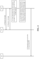
- the CU of 5G base station or a 5G base station can be conceptually divided into CP (Control Plane) and UF (User Plane). It is called CP-UP Split, for the F1 interface.
- the interface between CP and UP is called E1 interface, as shown in an example embodiment of FIG. 1 .
- Control Plane includes, for example, Radio Resource Management (RRM), Radio Resource Control (RRC) and Packet Data Convergence Protocol C-Plane (PDCP-C) function of a 5G base station.
- RRM Radio Resource Management
- RRC Radio Resource Control
- PDCP-C Packet Data Convergence Protocol C-Plane
- User Plane includes, for example, Packet Data Convergence Protocol U-Plane (PDCP-U) function of a 5G base station.
- the present document provides multiple ways by which QoS can be implemented in architectures such as the upcoming 5G networks.
- the disclosed techniques can be implemented in a wireless system architecture in which the control plane and the user plane are logically separated, as described with respect to the 5G systems.
- Certain concepts from 5G architecture are used to describe various embodiments only for the ease of understanding and the disclosed techniques can be embodied in other communication networks also.
- Example embodiments 1 and 2 described in the present document describe implementing the QoS method in a 5G system in a scenario where the control plane user plane is separated.
- the base station controls to send an update message to the base station user plane so that the base station user plane knows in time the flow of QoS Flow to the DRB (including the upstream direction and the downstream direction) and / or updates the base station user plane and which QoS flow needs to be performed NAS Reflective.
- the base station user plane stores information from the update message: QoS Flow to DRB mapping (including upstream and downstream), and / or QoS Flow information that requires NAS Reflective.
- the base station user plane receives a downlink packet from the core network according to the latest downlink direction QoS Flow to DRB mapping relationship.
- the downlink packet may include a quality of service flow identity (QFI).
- QFI quality of service flow identity
- the base station may use the QFI which DRB the packet should be mapped to when transmitting downstream over the wireless interface.
- the base station may decide the mapping according to the rules of the stored NAS Reflective QoS Flow information, downlink data packets contained in the QFI, and determine whether the downlink packet in the wireless interface to send with QFI.
- the base station when the base station user plane receives a downlink packet from the core network, the base station may perform mapping according to the QoS flow corresponding to the QFI contained in the downlink packet.
- the base station may perform mapping according to the QoS flow corresponding to the QFI contained in the downlink packet.
- the user plane sends a request message to the base station control plane to request the base station control plane to determine the mapping relationship of the QoS flow to the DRB in the downlink direction.
- the base station control plane determines the mapping relationship of the associated QoS flow downstream to the DRB.
- the base station control plane responds to the response message.
- the control plane may carry one or more downlink QoS flow to the DRB mapping relationships, as determined by the base station control plane.
- the base station control plane may optionally also carry one or more relevant DRB configuration information (for the base station user plane to establish the relevant DRB).
- the base station user plane stores information from the response message in the form of a downstream direction QoS Flow to DRB mapping.
- the base station user plane determines the DRB to which the downstream packet should be mapped when the downlink packet is to be transmitted according to the latest downstream direction QoS Flow to the DRB mapping relationship for the downlink packets that have not yet been transmitted on the radio interface. If it is found that the corresponding DRB has not been established, the corresponding DRB may be obtained, e.g., based on the configuration information of the DRB from the response message.
- the base station user plane when the base station user plane receives the uplink packet sent from the UE on a predetermined or default DRB (default DRB), the user plane checks whether the QoS flow of the QFI contained in these uplink packets has the corresponding upstream direction QoS Flow to DRB mapping relationship on the base station user plane. If a correspondence is not found, the base station user plane sends a request message to the base station control plane to request the base station control plane to determine the upstream direction of the QoS flow to the DRB mapping relationship.
- default DRB default DRB
- the base station control plane determines the mapping relation of the relevant QoS flow to the DRB and configures the mapping relation of the relevant QoS flow to the DRB to the UE through an upper layer message such as the RRC (Radio Resource Control) message, or the AS Reflective to configure the mapping of the QoS flow upstream to the DRB to the UE.
- RRC Radio Resource Control
- the base station controls the response message to carry one or more upstream QoS flows to the DRB mapping relationship determined by the base station control plane.
- AS Reflective mode When passing through the AS Reflective mode, it also carries an indication that AS Reflective is to be used.
- the base station user plane is instructed to use AS Reflective.
- the corresponding downlink packet e.g., the corresponding QoS flow of the QFI contained in the downstream packet Flow
- the corresponding QoS flow of the QFI contained in the downstream packet Flow is made to be AS Reflective according to the indication in the response message.
- the QFI and AS Reflective bits are sent when the radio interface is sent for the UE to generate the associated QoS flow to the DRB mapping relationship.
- the base station user plane stores the information from the response message that includes the upstream direction QoS Flow to the DRB mapping relationship.
- the QoS flow of the QFI included in the uplink packet can be found based on the latest upstream QoS flow to the DRB mapping relationship stored at the base station.
- the user plane may have a corresponding uplink direction QoS Flow to the DRB mapping relationship. In this case, the base station user plane no longer has to send the request message to the base station control plane.
- the disclosed techniques can be used to implement a new QoS mechanism in the 5G system can be implemented when there is control plane-user plane separation.
- Step 1.1 When the base station control plane receives the control information about the network, such as the addition or deletion of QoS flow from the core network, or when the base station control plane remaps the mapping of the QoS Flow to the DRB, the base station provides (including uplink and downlink direction) an update status of the QoS flow to the DRB.
- the update message may carry the associated QoS flow in the upstream direction and / or the downlink direction to the DRB.
- the update message may include each mapping relationship includes QFI (QoS Flow ID, Quality of Service ID) and DRB ID (Data Radio Bearer ID). Alternatively, in some embodiments, the update message may only transmit values that have changed from a previously sent update.
- Step 1.2 The base station user plane saves the information from the update message.
- This information includes QoS Flow to DRB mapping including mapping for both upstream and downstream directions.
- step 1.3 when the base station user plane receives a downlink packet from the core network, it is determined that the downlink packet should be mapped to the radio interface, and a corresponding DRB, according to the latest downstream direction QoS Flow to the DRB mapping relationship and the QFI included in the downlink packet.
- Step 1.4 The base station user plane sends the downlink packet to the UE on the corresponding DRB at the radio interface.
- step 2.1 when the base station control plane receives the control information of the NAS Reflective from the core network about the certain QoS flow, the base station controls to send the update message to the base station user plane so that the base station user plane knows which QoS flows are to be NAS Reflective.
- the update message carries one or more QFIs that can be used for QoS filtering for NAS Reflective.
- Step 2.2 The base station user plane saves the information from the update message, including the QoS flow information of NAS Reflective.
- Step 2.3 When the base station user plane receives the downlink packet from the core network, it searches the QoS information of the NAS Reflective according to the saved information and the QFI included in the downlink packet to determine whether the downstream packet is to carry the QFI. Specifically the user plane may determine whether the QFI contained in the downstream packet is the QFI of the QoS flow that is to be NAS Reflective. If not, the downstream packet is sent to the UE via the radio interface, without QFI to save wireless resources. If so, QFI is used in the packet sent to the UE.
- Step 2.4 The base station user plane sends a downlink packet with QFI or without QFI to the UE at the radio interface.
- step 3.1 when the base station user plane receives the downlink packet from the core network, it is found that there is no corresponding downlink QoS flow to the DRB mapping relationship on the base station user plane according to the QoS flow corresponding to the QFI contained in the downlink packet. In this case, without additional information, there is no way to determine the downlink packet in the wireless interface to send to which DRB should be mapped.
- the base station user plane sends a request message to the base station control plane to request the base station control plane to determine the mapping of the QoS flow to the DRB in the downlink direction, and the request message carries one or more QFI of the QoS flow that needs to determine the mapping relationship to the DRB.
- the base station control plane determines the mapping relationship of the related QoS flow to the DRB. To achieve this, the base station control plane responds to the response message, carrying one or more downlink QoS flows to the DRB mapping relationship determined by the base station control plane.
- the response can optionally carry one or more related DRB configuration information (for the base station user plane to establish the relevant DRB).
- Step 3.3 The base station user plane saves the information from the response message, including the downstream direction QoS Flow to the DRB mapping relationship.
- the base station user plane determines the DRB to which the downlink packet should be mapped when the downlink packet is transmitted according to the latest downlink QoS flow to the DRB mapping relationship for the downlink packets that have not yet been transmitted on the radio interface. If it is found that the corresponding DRB has not been established, the corresponding DRB (based on the configuration information of the DRB from the response message) is established.
- Step 3.5 The base station user plane sends the downlink packet to the UE on the corresponding DRB at the radio interface.
- step 4.1 when the base station user plane receives the uplink packet sent from the UE on a Default DRB ("Default DRB"), the user plane checks whether the QoS flow corresponding to the QFI contained in the uplink packet has a corresponding uplink direction QoS Flow to DRB mapping available at the base station user plane.
- Default DRB Default DRB
- Step 4.2 the base station user plane sends a request message to the base station control plane to request the base station control plane to determine the mapping relationship of the QoS flow to the DRB in the uplink direction.
- the request message includes one or more QoS flows for which the mapping relationship of the uplink direction to the DRB QFI is to be determined.
- Step 4.3 The base station control plane determines the mapping relationship between the uplink traffic direction QoS flow and the DRB.
- the base station control plane configures the mapping relation of the relevant QoS flow to the DRB through an RRC (Radio Resource Control) message.
- RRC Radio Resource Control
- Step 4.4 The base station control plane sends a response message that carries the mapping relationship of one or more upstream QoS flows to the DRB, as determined by the base station control plane.
- Step 4.5 The base station user plane saves the information from the response message, including the upstream direction QoS Flow to the DRB mapping relationship.
- step 4.6 when the base station user plane receives the uplink packet transmitted from the UE on the Default DRB, the base station user plane can find the QoS flow of the QFI contained in the uplink packet according to the latest upstream QoS flow to the DRB mapping relationship has a corresponding uplink QoS mapping to the DRB on the base station user plane, and the base station user plane no longer needs to send the request message to the base station control plane.
- the base station control plane determines the mapping relationship of the relevant QoS flow to the DRB; the base station control plane sends a response message that carries one or more upstream QoS flows to the DRB mapping relationship determined by the base station control plane and AS Reflective instructions.
- Step 5.4 The base station user plane is instructed that AS Reflective is to be used.
- the downlink packet from the core network is received, corresponding to the corresponding downlink packet (that is, the QFI corresponding to the downlink packet) indicates that the AS Reflective is used, the QFI and AS Reflective bit is to be sent to the UE to generate the mapping of the associated uplink QoS flow to the DRB.
- FIG. 7 is a flowchart of an example wireless communication method 700.
- the method 700 may be implemented by a base station such as the gNB.
- the method 700 includes providing (702), a quality of service (QoS) update from a control plane of a base station to a user plane of the base station based on a QoS event, wherein the QoS update includes information indicative of a mapping between a QoS flow and corresponding radio resources for user data transmission.
- the QoS event may include receiving a notification from the core network about addition or deletion of at least one QoS flow from the network.
- the QoS event includes remapping between QoS flows and radio resources.
- the method 700 further includes storing (704), at the user plane, the mapping between the QoS flow and the radio resources.
- the mapping may be stored in a memory in the form of a look-up table that is controlled by the user plane. For example, only the user plane may be able to read or write to the look-up table.
- the method 700 also includes receiving (706), at the user plane, a downstream data packet of the QoS flow from a core network.
- the communication from the core network may be received on a wired or wireless interface.
- the method 700 includes transmitting (708) the downstream data packet in a downlink direction using the corresponding radio resources.
- FIG. 8 is a flowchart of an example of another wireless communication method 800.
- the method 800 includes providing (802), a quality of service (QoS) update from a control plane of a base station to a user plane of the base station based on a QoS event, wherein the QoS update includes information identifying one or more QoS flows that are symmetric.
- a symmetric QoS flow may be one for which a downlink QoS parameter for the one or more QoS flows is determinable for a corresponding uplink information.
- the NAS Reflective attribute defined in 5G may be a symmetric flow.
- the method 800 includes storing, at the user plane, identities of the one or more QoS flows that are symmetric.
- the identities may be stored in a memory access to which is exclusively controlled by the user plane.
- the method 800 includes receiving (806), at the user plane, a downstream data packet of a given QoS flow from a core network.
- the method 800 includes transmitting (808) the downstream data packet in a downlink direction using the corresponding radio resources.
- FIG. 9 is a flowchart of an example of another wireless communication method 900.
- a data packet for downstream transmission from a core network is received by a base station.
- the data packet may be received on a wired or a wireless communication connection.
- the data packet includes a quality of service flow indicator.
- the user plane obtains a mapping between the quality of service flow indicator and a radio resource for downstream transmission from a control plane of the base station.
- the user plane transmits the data packet in a downstream direction using the mapping obtained from the control plane.
- the user plane may decide, based on the quality of service flow indicator that a mapping is to be established (e.g., when no mapping is locally available at the user plane). The decision may be made by looking up information stored in a memory local to the user plane. For example, read or write access to the memory may only be available through the user plane.
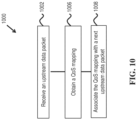
- FIG. 10 is a flowchart of an example of another wireless communication method 1000.
- a base station receives, on an uplink radio resource, a data packet for upstream transmission from a user equipment.
- the data packet includes a quality of service flow indicator.
- the user plane obtains a mapping between the quality of service flow indicator and an uplink radio resource from a control plane of the base station.
- the method 1000 includes associating, for a next data packet received on the uplink radio resource, a quality of service flow indicated by the quality of service flow indicator.
- the mapping between the quality of service flow indicator and the uplink radio resource is obtained when the user plane determines that the mapping is to be established, e.g., not available at the user plane.
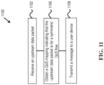
- FIG. 11 is a flowchart of an example of another wireless communication method 1100.
- the method 1100 includes receiving (1102), at a base station, on an uplink radio resource, a data packet for upstream transmission from a user equipment, wherein the data packet includes a quality of service flow indicator.
- the method 1100 includes selectively obtaining (1106), by the user plane, from a control plane of the base station, a mapping between the quality of service indicator and the uplink radio resource, wherein the mapping indicates that the mapping is of a symmetric type.
- the method 1100 includes transmitting (1108) a message to the user equipment indicating that the mapping is of the symmetric type.
- the method 1100 includes determining that the mapping is to be established because of non-availability of the mapping at the user plane and, in response, obtaining the mapping from the control plane.
- FIG. 12 is a block diagram of an example implementation of a wireless communication apparatus 1200.
- the methods 700, 800, 900, 1000, and 1100 may be implemented by the apparatus 1200.
- the apparatus 1200 may be a base station of a wireless network.
- the apparatus 1200 includes one or more processors, e.g., processor electronics 1210, transceiver circuitry 1215 and one or more antennaa 1220 for transmission and reception of wireless signals.
- the apparatus 1200 may include memory 1205 that may be used to store data and instructions used by the processor electronics 1210.
- the apparatus 1200 may also include an additional network interface to a core network or a network operator's additional equipment. This additional network interface, not explitly shown in FIG. 12 , may be wired (e.g., fiber or Ethernet) or wireless.
- FIG. 13 depicts an example of a wireless communication system 1300 in which the various techniques described herein can be implemented.
- the system 1300 includes a base station 1302 that may have a communication connection with core network (1312) and to a wireless communication medium 1304 to communicate with one or more user devices 1306.
- the user devices 1306 could be smartphones, tablets, machine to machine communication devices, Internet of Things (IoT) devices, and so on.
- IoT Internet of Things
- the disclosed and other embodiments, modules and the functional operations described in this document can be implemented in digital electronic circuitry, or in computer software, firmware, or hardware, including the structures disclosed in this document and their structural equivalents, or in combinations of one or more of them.
- the disclosed and other embodiments can be implemented as one or more computer program products, i.e., one or more modules of computer program instructions encoded on a computer readable medium for execution by, or to control the operation of, data processing apparatus.
- the computer readable medium can be a machine-readable storage device, a machine-readable storage substrate, a memory device, a composition of matter effecting a machine-readable propagated signal, or a combination of one or more them.
- data processing apparatus encompasses all apparatus, devices, and machines for processing data, including by way of example a programmable processor, a computer, or multiple processors or computers.
- the apparatus can include, in addition to hardware, code that creates an execution environment for the computer program in question, e.g., code that constitutes processor firmware, a protocol stack, a database management system, an operating system, or a combination of one or more of them.
- a propagated signal is an artificially generated signal, e.g., a machine-generated electrical, optical, or electromagnetic signal, that is generated to encode information for transmission to suitable receiver apparatus.
- a computer program (also known as a program, software, software application, script, or code) can be written in any form of programming language, including compiled or interpreted languages, and it can be deployed in any form, including as a stand alone program or as a module, component, subroutine, or other unit suitable for use in a computing environment.
- a computer program does not necessarily correspond to a file in a file system.
- a program can be stored in a portion of a file that holds other programs or data (e.g., one or more scripts stored in a markup language document), in a single file dedicated to the program in question, or in multiple coordinated files (e.g., files that store one or more modules, sub programs, or portions of code).
- a computer program can be deployed to be executed on one computer or on multiple computers that are located at one site or distributed across multiple sites and interconnected by a communication network.
- the processes and logic flows described in this document can be performed by one or more programmable processors executing one or more computer programs to perform functions by operating on input data and generating output.
- the processes and logic flows can also be performed by, and apparatus can also be implemented as, special purpose logic circuitry, e.g., an FPGA (field programmable gate array) or an ASIC (application specific integrated circuit).
- processors suitable for the execution of a computer program include, by way of example, both general and special purpose microprocessors, and any one or more processors of any kind of digital computer.
- a processor will receive instructions and data from a read only memory or a random access memory or both.
- the essential elements of a computer are a processor for performing instructions and one or more memory devices for storing instructions and data.
- a computer will also include, or be operatively coupled to receive data from or transfer data to, or both, one or more mass storage devices for storing data, e.g., magnetic, magneto optical disks, or optical disks.
- mass storage devices for storing data, e.g., magnetic, magneto optical disks, or optical disks.
- a computer need not have such devices.
- Computer readable media suitable for storing computer program instructions and data include all forms of non-volatile memory, media and memory devices, including by way of example semiconductor memory devices, e.g., EPROM, EEPROM, and flash memory devices; magnetic disks, e.g., internal hard disks or removable disks; magneto optical disks; and CD ROM and DVD-ROM disks.
- semiconductor memory devices e.g., EPROM, EEPROM, and flash memory devices
- magnetic disks e.g., internal hard disks or removable disks
- magneto optical disks e.g., CD ROM and DVD-ROM disks.
- the processor and the memory can be supplemented by, or incorporated in, special purpose logic circuitry.
Landscapes
- Engineering & Computer Science (AREA)
- Computer Networks & Wireless Communication (AREA)
- Signal Processing (AREA)
- Quality & Reliability (AREA)
- Computer Security & Cryptography (AREA)
- Mobile Radio Communication Systems (AREA)
Priority Applications (2)
| Application Number | Priority Date | Filing Date | Title |
|---|---|---|---|
| DK23172810.6T DK4228304T3 (da) | 2017-08-09 | 2017-08-09 | Implementering af servicekvalitet til adskillelse af brugerplan |
| EP23172810.6A EP4228304B1 (en) | 2017-08-09 | 2017-08-09 | Quality of service implementations for separating user plane |
Applications Claiming Priority (1)
| Application Number | Priority Date | Filing Date | Title |
|---|---|---|---|
| PCT/CN2017/096609 WO2019028697A1 (en) | 2017-08-09 | 2017-08-09 | QUALITY OF SERVICE IMPROVEMENTS FOR SEPARATING A USER PLAN |
Related Child Applications (2)
| Application Number | Title | Priority Date | Filing Date |
|---|---|---|---|
| EP23172810.6A Division-Into EP4228304B1 (en) | 2017-08-09 | 2017-08-09 | Quality of service implementations for separating user plane |
| EP23172810.6A Division EP4228304B1 (en) | 2017-08-09 | 2017-08-09 | Quality of service implementations for separating user plane |
Publications (3)
| Publication Number | Publication Date |
|---|---|
| EP3665924A1 EP3665924A1 (en) | 2020-06-17 |
| EP3665924A4 EP3665924A4 (en) | 2020-10-21 |
| EP3665924B1 true EP3665924B1 (en) | 2025-06-18 |
Family
ID=65272840
Family Applications (2)
| Application Number | Title | Priority Date | Filing Date |
|---|---|---|---|
| EP17920745.1A Active EP3665924B1 (en) | 2017-08-09 | 2017-08-09 | Quality of service implementations for separating user plane |
| EP23172810.6A Active EP4228304B1 (en) | 2017-08-09 | 2017-08-09 | Quality of service implementations for separating user plane |
Family Applications After (1)
| Application Number | Title | Priority Date | Filing Date |
|---|---|---|---|
| EP23172810.6A Active EP4228304B1 (en) | 2017-08-09 | 2017-08-09 | Quality of service implementations for separating user plane |
Country Status (8)
| Country | Link |
|---|---|
| US (3) | US11146984B2 (ko) |
| EP (2) | EP3665924B1 (ko) |
| JP (1) | JP6974587B2 (ko) |
| KR (1) | KR102327904B1 (ko) |
| CN (2) | CN113543214A (ko) |
| DK (1) | DK4228304T3 (ko) |
| RU (1) | RU2744016C1 (ko) |
| WO (1) | WO2019028697A1 (ko) |
Families Citing this family (9)
| Publication number | Priority date | Publication date | Assignee | Title |
|---|---|---|---|---|
| CN113543214A (zh) | 2017-08-09 | 2021-10-22 | 中兴通讯股份有限公司 | 用于分离用户面的服务质量实现 |
| CN110324857B (zh) * | 2018-03-28 | 2021-03-16 | 中国移动通信有限公司研究院 | 一种业务质量数据流的处理方法和装置 |
| CN119300082A (zh) * | 2018-04-04 | 2025-01-10 | 荣耀终端有限公司 | 通信方法和装置 |
| CN110753349B (zh) * | 2019-10-29 | 2020-10-27 | 西安交通大学 | 一种识别伪基站的方法及设备 |
| WO2022155916A1 (zh) * | 2021-01-22 | 2022-07-28 | Oppo广东移动通信有限公司 | 一种属性参数的调整方法及装置、通信设备 |
| WO2023060406A1 (en) * | 2021-10-11 | 2023-04-20 | Apple Inc. | Enhanced qos support for extended reality (xr) |
| CN114423031B (zh) * | 2022-02-17 | 2024-01-26 | 赛特斯信息科技股份有限公司 | 5g服务质量流与数据无线承载映射方法 |
| EP4505792A4 (en) * | 2022-06-24 | 2025-06-11 | ZTE Corporation | Methods and devices for transmitting quality of service information via user plane |
| US20230015829A1 (en) * | 2022-09-14 | 2023-01-19 | Intel Corporation | Apparatus, system, method and computer-implemented storage media to implement a per data packet quality of service requirement in a communication network |
Family Cites Families (58)
| Publication number | Priority date | Publication date | Assignee | Title |
|---|---|---|---|---|
| US8658203B2 (en) | 2004-05-03 | 2014-02-25 | Merrimack Pharmaceuticals, Inc. | Liposomes useful for drug delivery to the brain |
| KR101572272B1 (ko) * | 2009-04-21 | 2015-12-07 | 엘지전자 주식회사 | 다중 반송파 시스템에서 무선통신의 수행장치 및 방법 |
| CN103503352A (zh) * | 2010-12-02 | 2014-01-08 | 交互数字专利控股公司 | 在无线通信中使用干扰预测提高信道质量指示反馈准确度的系统和方法 |
| CN102355692A (zh) * | 2011-07-22 | 2012-02-15 | 电信科学技术研究院 | 配置业务质量测量及业务质量测量上报方法和设备 |
| WO2013177764A1 (zh) * | 2012-05-30 | 2013-12-05 | 华为技术有限公司 | 多流传输的调度方法和设备 |
| EP2891259A4 (en) * | 2012-08-31 | 2016-10-05 | Nokia Solutions & Networks Oy | OPTIMIZATIONS FOR FREQUENT TRANSMISSION OF SMALL DATA |
| CN104244426B (zh) * | 2013-06-09 | 2019-02-05 | 华为技术有限公司 | 一种数据无线承载drb的资源分配方法及装置 |
| US9485679B2 (en) * | 2013-06-19 | 2016-11-01 | Nsrs Comms Ireland Limited | Apparatus and method for analyzing the quality of a cell in a mobile device network |
| KR102094718B1 (ko) * | 2013-09-26 | 2020-05-27 | 삼성전자주식회사 | 무선 네트워크에서 학습에 기반한 중계 노드 선택 방법 및 중계 장치 |
| CN104683956B (zh) * | 2013-11-27 | 2018-01-26 | 普天信息技术研究院有限公司 | QoS控制方法和系统 |
| CN106332048B (zh) * | 2015-06-30 | 2022-08-19 | 华为技术有限公司 | 一种数据传输方法、无线网络节点和通信系统 |
| MY194704A (en) * | 2015-12-17 | 2022-12-15 | Huawei Tech Co Ltd | Qos guarantee method and gateway |
| US10959240B2 (en) | 2016-04-15 | 2021-03-23 | Qualcomm Incorporated | Providing quality-of-service in wireless communications |
| US11444850B2 (en) * | 2016-05-02 | 2022-09-13 | Huawei Technologies Co., Ltd. | Method and apparatus for communication network quality of service capability exposure |
| US10362507B2 (en) * | 2016-06-10 | 2019-07-23 | Huawei Technologies Co., Ltd. | Systems and method for quality of service monitoring, policy enforcement, and charging in a communications network |
| US10856265B2 (en) * | 2016-07-05 | 2020-12-01 | Lg Electronics Inc. | Method for selecting resource operation preferred by user in wireless communication system and device for same |
| CN109565703B (zh) * | 2016-08-01 | 2022-04-26 | 三星电子株式会社 | 用于管理无线通信网络中的数据通信的方法和设备 |
| WO2018030798A1 (en) | 2016-08-09 | 2018-02-15 | Samsung Electronics Co., Ltd. | Method and apparatus for managing user plane operation in wireless communication system |
| CN107889171B (zh) | 2016-09-30 | 2023-10-20 | 华为技术有限公司 | 无线通信方法、用户设备和接入网设备 |
| US20200178048A1 (en) * | 2016-10-06 | 2020-06-04 | Lg Electronics Inc. | V2x communication support method in wireless communication system |
| WO2018070689A1 (ko) * | 2016-10-11 | 2018-04-19 | 엘지전자(주) | 무선 통신 시스템에서의 반영형 서비스 퀄리티 적용 방법 및 이를 위한 장치 |
| WO2018075828A1 (en) | 2016-10-19 | 2018-04-26 | Convida Wireless, Llc | Apparatus |
| WO2018084678A2 (en) * | 2016-11-04 | 2018-05-11 | Samsung Electronics Co., Ltd. | Method and apparatus for provisioning quality of service in next radio |
| EP3547769B1 (en) * | 2016-11-27 | 2021-05-12 | LG Electronics Inc. | Deregistration method in wireless communication system and device therefor |
| US10716083B2 (en) * | 2016-12-15 | 2020-07-14 | Lg Electronics Inc. | Tracking area assignment method in wireless communication system and device therefor |
| WO2018124810A1 (ko) * | 2016-12-29 | 2018-07-05 | 엘지전자 주식회사 | Drb를 확립하는 방법 및 장치 |
| KR102155338B1 (ko) * | 2017-01-05 | 2020-09-11 | 엘지전자 주식회사 | Qos 플로우 대 drb 맵핑에 대한 규칙을 전송하는 방법 및 장치 |
| WO2018128452A1 (en) * | 2017-01-06 | 2018-07-12 | Lg Electronics Inc. | Method for transmitting lossless data packet based on quality of service (qos) framework in wireless communication system and a device therefor |
| ES2929669T3 (es) * | 2017-01-09 | 2022-11-30 | Lg Electronics Inc | Método para el interfuncionamiento entre redes en un sistema de comunicación inalámbrica y aparatos para el mismo |
| US11044643B2 (en) * | 2017-01-11 | 2021-06-22 | Telefonaktiebolaget Lm Ericsson (Publ) | 5G QoS flow to radio bearer remapping |
| US11115855B2 (en) * | 2017-01-13 | 2021-09-07 | Lg Electronics Inc. | Method for transmitting UL packet based on quality of service (QoS) flow in wireless communication system and a device therefor |
| EP3469828B1 (en) * | 2017-02-01 | 2022-08-17 | LG Electronics Inc. | Method for performing reflective quality of service (qos) in wireless communication system and a device therefor |
| CN108390830B (zh) | 2017-02-03 | 2024-03-05 | 华为技术有限公司 | 一种QoS流处理方法、设备和通信系统 |
| WO2018159959A1 (en) * | 2017-03-01 | 2018-09-07 | Lg Electronics Inc. | Method for transmitting tcp ack packet in wireless communication system and a device therefor |
| EP3598812B1 (en) * | 2017-03-16 | 2022-02-09 | LG Electronics Inc. | Notifying a mobility event in a wireless communication system |
| EP3606115B1 (en) * | 2017-03-20 | 2022-05-04 | LG Electronics Inc. | Method for interaction between layers in wireless communication system and apparatus therefor |
| KR102265907B1 (ko) * | 2017-03-22 | 2021-06-16 | 엘지전자 주식회사 | 무선 통신 시스템에서 서비스 품질 (QoS) 구조 기반으로 상향링크 패킷을 전송하는 방법 및 이를 위한 장치 |
| EP3603168B1 (en) * | 2017-03-23 | 2022-01-05 | LG Electronics Inc. | Method for transmitting lossless data packet based on quality of service (qos) framework in wireless communication system and a device therefor |
| WO2018199622A1 (en) * | 2017-04-25 | 2018-11-01 | Lg Electronics Inc. | Method and device for receiving data unit |
| WO2018203622A1 (en) * | 2017-05-02 | 2018-11-08 | Lg Electronics Inc. | Method and device for receiving data unit |
| WO2018203697A1 (en) * | 2017-05-04 | 2018-11-08 | Lg Electronics Inc. | Method and device for transmitting data unit |
| EP4138461A1 (en) * | 2017-05-05 | 2023-02-22 | Apple Inc. | Access control mechanism |
| CN110537375B (zh) * | 2017-05-16 | 2022-08-02 | 苹果公司 | 每ue网络控制的小间隙(ncsg)信令 |
| US11363623B2 (en) * | 2017-05-30 | 2022-06-14 | Lg Electronics Inc. | Method and user equipment for transmitting uplink data, and method and base station for receiving uplink data |
| US10638372B2 (en) * | 2017-06-01 | 2020-04-28 | Huawei Technologies Co., Ltd. | Geographic dispersion of radio access network (RAN) node functions |
| US10499376B2 (en) | 2017-06-16 | 2019-12-03 | Kt Corporation | Methods for managing resource based on open interface and apparatuses thereof |
| WO2018229299A1 (en) * | 2017-06-16 | 2018-12-20 | Telefonaktiebolaget Lm Ericsson (Publ) | Ue context handling in a disaggregated radio access node |
| EP3639579A4 (en) * | 2017-06-16 | 2021-01-20 | Apple Inc. | POWER INCREASE AND CONTROL IN NEW RADIO (NR) DEVICES |
| US11184838B2 (en) * | 2017-06-17 | 2021-11-23 | Lg Electronics Inc. | Method for registering terminal in wireless communication system and apparatus therefor |
| EP3643107B1 (en) * | 2017-06-19 | 2024-03-06 | Apple Inc. | Separation of control plane and user plane in new radio (nr) systems |
| EP3643026A4 (en) * | 2017-06-21 | 2021-03-17 | Apple Inc. | SYNCHRONIZATION SIGNAL BLOCK (SS) COLLISION TREATMENT |
| CN115664619B (zh) * | 2017-06-26 | 2026-03-17 | 苹果公司 | 用于参考信号的冲突处理的方法、装置和计算机程序产品 |
| EP3432633B1 (en) * | 2017-07-20 | 2019-10-02 | ASUSTek Computer Inc. | Method and apparatus for servicing qos (quality of service) flow in a wireless communication system |
| US10798754B2 (en) * | 2017-07-24 | 2020-10-06 | Asustek Computer Inc. | Method and apparatus for serving quality of service (QOS) flow in a wireless communication system |
| CN115459894B (zh) * | 2017-08-02 | 2025-08-26 | 苹果公司 | 用于新空口物理上行链路控制信道的序列设计和资源分配的方法、装置和介质 |
| EP3664535B1 (en) * | 2017-08-04 | 2024-06-26 | Honor Device Co., Ltd. | Method for acquiring data radio bearer identifier and base station |
| CN113543214A (zh) | 2017-08-09 | 2021-10-22 | 中兴通讯股份有限公司 | 用于分离用户面的服务质量实现 |
| US20190342874A1 (en) * | 2018-05-04 | 2019-11-07 | Intel Corporation | Interlace-Based Uplink Physical Channel Design for New Radio-Unlicensed (NR-U) |
-
2017
- 2017-08-09 CN CN202110882049.4A patent/CN113543214A/zh active Pending
- 2017-08-09 EP EP17920745.1A patent/EP3665924B1/en active Active
- 2017-08-09 JP JP2020506943A patent/JP6974587B2/ja active Active
- 2017-08-09 CN CN201780093823.5A patent/CN110999355B/zh active Active
- 2017-08-09 RU RU2020109671A patent/RU2744016C1/ru active
- 2017-08-09 WO PCT/CN2017/096609 patent/WO2019028697A1/en not_active Ceased
- 2017-08-09 EP EP23172810.6A patent/EP4228304B1/en active Active
- 2017-08-09 DK DK23172810.6T patent/DK4228304T3/da active
- 2017-08-09 KR KR1020207006764A patent/KR102327904B1/ko active Active
-
2020
- 2020-02-05 US US16/783,114 patent/US11146984B2/en active Active
-
2021
- 2021-09-14 US US17/474,494 patent/US11785496B2/en active Active
-
2023
- 2023-08-30 US US18/458,855 patent/US12375970B2/en active Active
Also Published As
| Publication number | Publication date |
|---|---|
| WO2019028697A1 (en) | 2019-02-14 |
| CN110999355A (zh) | 2020-04-10 |
| US20210409997A1 (en) | 2021-12-30 |
| JP2020530237A (ja) | 2020-10-15 |
| US20200178109A1 (en) | 2020-06-04 |
| DK4228304T3 (da) | 2025-06-10 |
| RU2744016C1 (ru) | 2021-03-02 |
| US12375970B2 (en) | 2025-07-29 |
| US11785496B2 (en) | 2023-10-10 |
| KR20200035134A (ko) | 2020-04-01 |
| EP3665924A4 (en) | 2020-10-21 |
| EP3665924A1 (en) | 2020-06-17 |
| CN113543214A (zh) | 2021-10-22 |
| US20230413103A1 (en) | 2023-12-21 |
| CN110999355B (zh) | 2021-07-27 |
| EP4228304B1 (en) | 2025-05-14 |
| EP4228304A1 (en) | 2023-08-16 |
| KR102327904B1 (ko) | 2021-11-19 |
| US11146984B2 (en) | 2021-10-12 |
| JP6974587B2 (ja) | 2021-12-01 |
Similar Documents
| Publication | Publication Date | Title |
|---|---|---|
| US12375970B2 (en) | Quality of service implementations for separating user plane | |
| CN104363598B (zh) | 一种drb映射方法及装置 | |
| EP3403464B1 (en) | Transmitting communication device, receiving communication device, methods performed thereby in the context of network slicing and computer program | |
| CN112423340A (zh) | 一种用户面信息上报方法及装置 | |
| EP3855839A1 (en) | Method and apparatus for distribution and synchronization of radio resource assignments in a wireless communication system | |
| CN114731681B (zh) | 在v2x资源感测和选择中利用sl-rsrp的通信装置和通信方法 | |
| JP7546003B2 (ja) | 解放されたリソースを利用する通信装置および通信方法 | |
| WO2024098632A1 (en) | Systems and methods for determining network capability via control plane | |
| JP7604503B2 (ja) | 予約されたリソースを利用する通信装置および通信方法 | |
| CN119698904A (zh) | 涉及上行链路配置的通信设备和基站 | |
| EP3369277B1 (en) | Method and apparatus for implementing signalling to re-configure logical channels | |
| WO2024156140A1 (en) | Systems and methods for determining network capability via user plane | |
| US20250338297A1 (en) | Communication apparatuses and communication methods for sidelink co-channel coexistence of lte and nr | |
| JP2026508089A (ja) | マルチprach送信のためのroグループリソース | |
| GB2637349A (en) | Method, apparatus and computer program | |
| WO2024219190A1 (ja) | 端末、基地局、及び、通信方法 | |
| WO2024171520A1 (ja) | 基地局、端末及び通信方法 | |
| JP2025515336A (ja) | 空間/周波数領域測定を伴う通信装置および基地局 | |
| WO2023100471A1 (ja) | 基地局、端末及び通信方法 |
Legal Events
| Date | Code | Title | Description |
|---|---|---|---|
| STAA | Information on the status of an ep patent application or granted ep patent |
Free format text: STATUS: THE INTERNATIONAL PUBLICATION HAS BEEN MADE |
|
| PUAI | Public reference made under article 153(3) epc to a published international application that has entered the european phase |
Free format text: ORIGINAL CODE: 0009012 |
|
| STAA | Information on the status of an ep patent application or granted ep patent |
Free format text: STATUS: REQUEST FOR EXAMINATION WAS MADE |
|
| 17P | Request for examination filed |
Effective date: 20200303 |
|
| AK | Designated contracting states |
Kind code of ref document: A1 Designated state(s): AL AT BE BG CH CY CZ DE DK EE ES FI FR GB GR HR HU IE IS IT LI LT LU LV MC MK MT NL NO PL PT RO RS SE SI SK SM TR |
|
| AX | Request for extension of the european patent |
Extension state: BA ME |
|
| RIC1 | Information provided on ipc code assigned before grant |
Ipc: H04W 72/08 20090101ALI20200519BHEP Ipc: H04W 12/06 20090101AFI20200519BHEP Ipc: H04W 28/02 20090101ALI20200519BHEP Ipc: H04W 72/04 20090101ALI20200519BHEP |
|
| A4 | Supplementary search report drawn up and despatched |
Effective date: 20200917 |
|
| RIC1 | Information provided on ipc code assigned before grant |
Ipc: H04W 72/04 20090101ALI20200911BHEP Ipc: H04W 72/08 20090101ALI20200911BHEP Ipc: H04W 28/02 20090101ALI20200911BHEP Ipc: H04W 12/06 20090101AFI20200911BHEP |
|
| DAV | Request for validation of the european patent (deleted) | ||
| DAX | Request for extension of the european patent (deleted) | ||
| STAA | Information on the status of an ep patent application or granted ep patent |
Free format text: STATUS: EXAMINATION IS IN PROGRESS |
|
| 17Q | First examination report despatched |
Effective date: 20220411 |
|
| REG | Reference to a national code |
Free format text: PREVIOUS MAIN CLASS: H04W0012060000 Ref country code: DE Ref legal event code: R079 Ref document number: 602017090076 Country of ref document: DE Free format text: PREVIOUS MAIN CLASS: H04W0012060000 Ipc: H04W0072543000 |
|
| RIC1 | Information provided on ipc code assigned before grant |
Ipc: H04W 28/02 20090101ALI20241007BHEP Ipc: H04W 12/06 20090101ALI20241007BHEP Ipc: H04W 72/543 20230101AFI20241007BHEP |
|
| GRAP | Despatch of communication of intention to grant a patent |
Free format text: ORIGINAL CODE: EPIDOSNIGR1 |
|
| STAA | Information on the status of an ep patent application or granted ep patent |
Free format text: STATUS: GRANT OF PATENT IS INTENDED |
|
| INTG | Intention to grant announced |
Effective date: 20250114 |
|
| GRAS | Grant fee paid |
Free format text: ORIGINAL CODE: EPIDOSNIGR3 |
|
| GRAA | (expected) grant |
Free format text: ORIGINAL CODE: 0009210 |
|
| STAA | Information on the status of an ep patent application or granted ep patent |
Free format text: STATUS: THE PATENT HAS BEEN GRANTED |
|
| AK | Designated contracting states |
Kind code of ref document: B1 Designated state(s): AL AT BE BG CH CY CZ DE DK EE ES FI FR GB GR HR HU IE IS IT LI LT LU LV MC MK MT NL NO PL PT RO RS SE SI SK SM TR |
|
| REG | Reference to a national code |
Ref country code: GB Ref legal event code: FG4D |
|
| REG | Reference to a national code |
Ref country code: CH Ref legal event code: EP |
|
| REG | Reference to a national code |
Ref country code: DE Ref legal event code: R096 Ref document number: 602017090076 Country of ref document: DE |
|
| REG | Reference to a national code |
Ref country code: CH Ref legal event code: EP |
|
| REG | Reference to a national code |
Ref country code: IE Ref legal event code: FG4D |
|
| REG | Reference to a national code |
Ref country code: SE Ref legal event code: TRGR |
|
| PG25 | Lapsed in a contracting state [announced via postgrant information from national office to epo] |
Ref country code: FI Free format text: LAPSE BECAUSE OF FAILURE TO SUBMIT A TRANSLATION OF THE DESCRIPTION OR TO PAY THE FEE WITHIN THE PRESCRIBED TIME-LIMIT Effective date: 20250618 |
|
| PGFP | Annual fee paid to national office [announced via postgrant information from national office to epo] |
Ref country code: DE Payment date: 20250708 Year of fee payment: 9 |
|
| REG | Reference to a national code |
Ref country code: LT Ref legal event code: MG9D |
|
| PG25 | Lapsed in a contracting state [announced via postgrant information from national office to epo] |
Ref country code: GR Free format text: LAPSE BECAUSE OF FAILURE TO SUBMIT A TRANSLATION OF THE DESCRIPTION OR TO PAY THE FEE WITHIN THE PRESCRIBED TIME-LIMIT Effective date: 20250919 Ref country code: NO Free format text: LAPSE BECAUSE OF FAILURE TO SUBMIT A TRANSLATION OF THE DESCRIPTION OR TO PAY THE FEE WITHIN THE PRESCRIBED TIME-LIMIT Effective date: 20250918 |
|
| PGFP | Annual fee paid to national office [announced via postgrant information from national office to epo] |
Ref country code: TR Payment date: 20250730 Year of fee payment: 9 |
|
| PG25 | Lapsed in a contracting state [announced via postgrant information from national office to epo] |
Ref country code: BG Free format text: LAPSE BECAUSE OF FAILURE TO SUBMIT A TRANSLATION OF THE DESCRIPTION OR TO PAY THE FEE WITHIN THE PRESCRIBED TIME-LIMIT Effective date: 20250618 |
|
| PGFP | Annual fee paid to national office [announced via postgrant information from national office to epo] |
Ref country code: GB Payment date: 20250710 Year of fee payment: 9 |
|
| PG25 | Lapsed in a contracting state [announced via postgrant information from national office to epo] |
Ref country code: HR Free format text: LAPSE BECAUSE OF FAILURE TO SUBMIT A TRANSLATION OF THE DESCRIPTION OR TO PAY THE FEE WITHIN THE PRESCRIBED TIME-LIMIT Effective date: 20250618 |
|
| PGFP | Annual fee paid to national office [announced via postgrant information from national office to epo] |
Ref country code: FR Payment date: 20250708 Year of fee payment: 9 |
|
| PGFP | Annual fee paid to national office [announced via postgrant information from national office to epo] |
Ref country code: SE Payment date: 20250710 Year of fee payment: 9 |
|
| PG25 | Lapsed in a contracting state [announced via postgrant information from national office to epo] |
Ref country code: RS Free format text: LAPSE BECAUSE OF FAILURE TO SUBMIT A TRANSLATION OF THE DESCRIPTION OR TO PAY THE FEE WITHIN THE PRESCRIBED TIME-LIMIT Effective date: 20250918 |
|
| REG | Reference to a national code |
Ref country code: NL Ref legal event code: MP Effective date: 20250618 |
|
| PG25 | Lapsed in a contracting state [announced via postgrant information from national office to epo] |
Ref country code: LV Free format text: LAPSE BECAUSE OF FAILURE TO SUBMIT A TRANSLATION OF THE DESCRIPTION OR TO PAY THE FEE WITHIN THE PRESCRIBED TIME-LIMIT Effective date: 20250618 |
|
| PG25 | Lapsed in a contracting state [announced via postgrant information from national office to epo] |
Ref country code: NL Free format text: LAPSE BECAUSE OF FAILURE TO SUBMIT A TRANSLATION OF THE DESCRIPTION OR TO PAY THE FEE WITHIN THE PRESCRIBED TIME-LIMIT Effective date: 20250618 |
|
| PG25 | Lapsed in a contracting state [announced via postgrant information from national office to epo] |
Ref country code: PT Free format text: LAPSE BECAUSE OF FAILURE TO SUBMIT A TRANSLATION OF THE DESCRIPTION OR TO PAY THE FEE WITHIN THE PRESCRIBED TIME-LIMIT Effective date: 20251020 |
|
| REG | Reference to a national code |
Ref country code: AT Ref legal event code: MK05 Ref document number: 1805382 Country of ref document: AT Kind code of ref document: T Effective date: 20250618 |
|
| PG25 | Lapsed in a contracting state [announced via postgrant information from national office to epo] |
Ref country code: IS Free format text: LAPSE BECAUSE OF FAILURE TO SUBMIT A TRANSLATION OF THE DESCRIPTION OR TO PAY THE FEE WITHIN THE PRESCRIBED TIME-LIMIT Effective date: 20251018 |
|
| PG25 | Lapsed in a contracting state [announced via postgrant information from national office to epo] |
Ref country code: AT Free format text: LAPSE BECAUSE OF FAILURE TO SUBMIT A TRANSLATION OF THE DESCRIPTION OR TO PAY THE FEE WITHIN THE PRESCRIBED TIME-LIMIT Effective date: 20250618 Ref country code: SM Free format text: LAPSE BECAUSE OF FAILURE TO SUBMIT A TRANSLATION OF THE DESCRIPTION OR TO PAY THE FEE WITHIN THE PRESCRIBED TIME-LIMIT Effective date: 20250618 |
|
| PG25 | Lapsed in a contracting state [announced via postgrant information from national office to epo] |
Ref country code: CZ Free format text: LAPSE BECAUSE OF FAILURE TO SUBMIT A TRANSLATION OF THE DESCRIPTION OR TO PAY THE FEE WITHIN THE PRESCRIBED TIME-LIMIT Effective date: 20250618 |
|
| PG25 | Lapsed in a contracting state [announced via postgrant information from national office to epo] |
Ref country code: PL Free format text: LAPSE BECAUSE OF FAILURE TO SUBMIT A TRANSLATION OF THE DESCRIPTION OR TO PAY THE FEE WITHIN THE PRESCRIBED TIME-LIMIT Effective date: 20250618 |
|
| PG25 | Lapsed in a contracting state [announced via postgrant information from national office to epo] |
Ref country code: EE Free format text: LAPSE BECAUSE OF FAILURE TO SUBMIT A TRANSLATION OF THE DESCRIPTION OR TO PAY THE FEE WITHIN THE PRESCRIBED TIME-LIMIT Effective date: 20250618 |
|
| PG25 | Lapsed in a contracting state [announced via postgrant information from national office to epo] |
Ref country code: RO Free format text: LAPSE BECAUSE OF FAILURE TO SUBMIT A TRANSLATION OF THE DESCRIPTION OR TO PAY THE FEE WITHIN THE PRESCRIBED TIME-LIMIT Effective date: 20250618 Ref country code: SK Free format text: LAPSE BECAUSE OF FAILURE TO SUBMIT A TRANSLATION OF THE DESCRIPTION OR TO PAY THE FEE WITHIN THE PRESCRIBED TIME-LIMIT Effective date: 20250618 |
|
| PG25 | Lapsed in a contracting state [announced via postgrant information from national office to epo] |
Ref country code: ES Free format text: LAPSE BECAUSE OF FAILURE TO SUBMIT A TRANSLATION OF THE DESCRIPTION OR TO PAY THE FEE WITHIN THE PRESCRIBED TIME-LIMIT Effective date: 20250618 |
|
| REG | Reference to a national code |
Ref country code: CH Ref legal event code: H13 Free format text: ST27 STATUS EVENT CODE: U-0-0-H10-H13 (AS PROVIDED BY THE NATIONAL OFFICE) Effective date: 20260324 |
|
| PG25 | Lapsed in a contracting state [announced via postgrant information from national office to epo] |
Ref country code: MC Free format text: LAPSE BECAUSE OF FAILURE TO SUBMIT A TRANSLATION OF THE DESCRIPTION OR TO PAY THE FEE WITHIN THE PRESCRIBED TIME-LIMIT Effective date: 20250618 |
|
| PG25 | Lapsed in a contracting state [announced via postgrant information from national office to epo] |
Ref country code: DK Free format text: LAPSE BECAUSE OF FAILURE TO SUBMIT A TRANSLATION OF THE DESCRIPTION OR TO PAY THE FEE WITHIN THE PRESCRIBED TIME-LIMIT Effective date: 20250618 |
|
| PG25 | Lapsed in a contracting state [announced via postgrant information from national office to epo] |
Ref country code: IT Free format text: LAPSE BECAUSE OF FAILURE TO SUBMIT A TRANSLATION OF THE DESCRIPTION OR TO PAY THE FEE WITHIN THE PRESCRIBED TIME-LIMIT Effective date: 20250618 Ref country code: LU Free format text: LAPSE BECAUSE OF NON-PAYMENT OF DUE FEES Effective date: 20250809 |
|
| PLBE | No opposition filed within time limit |
Free format text: ORIGINAL CODE: 0009261 |
|
| STAA | Information on the status of an ep patent application or granted ep patent |
Free format text: STATUS: NO OPPOSITION FILED WITHIN TIME LIMIT |