EP3666322A1 - Herzklappenfreisetzungskatheter und freisetzungssystem - Google Patents
Herzklappenfreisetzungskatheter und freisetzungssystem Download PDFInfo
- Publication number
- EP3666322A1 EP3666322A1 EP18842960.9A EP18842960A EP3666322A1 EP 3666322 A1 EP3666322 A1 EP 3666322A1 EP 18842960 A EP18842960 A EP 18842960A EP 3666322 A1 EP3666322 A1 EP 3666322A1
- Authority
- EP
- European Patent Office
- Prior art keywords
- hollow
- delivery catheter
- outer tube
- segment
- sheath
- Prior art date
- Legal status (The legal status is an assumption and is not a legal conclusion. Google has not performed a legal analysis and makes no representation as to the accuracy of the status listed.)
- Granted
Links
Images


Classifications
-
- A—HUMAN NECESSITIES
- A61—MEDICAL OR VETERINARY SCIENCE; HYGIENE
- A61F—FILTERS IMPLANTABLE INTO BLOOD VESSELS; PROSTHESES; DEVICES PROVIDING PATENCY TO, OR PREVENTING COLLAPSING OF, TUBULAR STRUCTURES OF THE BODY, e.g. STENTS; ORTHOPAEDIC, NURSING OR CONTRACEPTIVE DEVICES; FOMENTATION; TREATMENT OR PROTECTION OF EYES OR EARS; BANDAGES, DRESSINGS OR ABSORBENT PADS; FIRST-AID KITS
- A61F2/00—Filters implantable into blood vessels; Prostheses, i.e. artificial substitutes or replacements for parts of the body; Appliances for connecting them with the body; Devices providing patency to, or preventing collapsing of, tubular structures of the body, e.g. stents
- A61F2/02—Prostheses implantable into the body
- A61F2/24—Heart valves ; Vascular valves, e.g. venous valves; Heart implants, e.g. passive devices for improving the function of the native valve or the heart muscle; Transmyocardial revascularisation [TMR] devices; Valves implantable in the body
- A61F2/2427—Devices for manipulating or deploying heart valves during implantation
- A61F2/2436—Deployment by retracting a sheath
-
- A—HUMAN NECESSITIES
- A61—MEDICAL OR VETERINARY SCIENCE; HYGIENE
- A61M—DEVICES FOR INTRODUCING MEDIA INTO, OR ONTO, THE BODY; DEVICES FOR TRANSDUCING BODY MEDIA OR FOR TAKING MEDIA FROM THE BODY; DEVICES FOR PRODUCING OR ENDING SLEEP OR STUPOR
- A61M25/00—Catheters; Hollow probes
- A61M25/01—Introducing, guiding, advancing, emplacing or holding catheters
- A61M25/0105—Steering means as part of the catheter or advancing means; Markers for positioning
- A61M25/0133—Tip steering devices
- A61M25/0138—Tip steering devices having flexible regions as a result of weakened outer material, e.g. slots, slits, cuts, joints or coils
-
- A—HUMAN NECESSITIES
- A61—MEDICAL OR VETERINARY SCIENCE; HYGIENE
- A61F—FILTERS IMPLANTABLE INTO BLOOD VESSELS; PROSTHESES; DEVICES PROVIDING PATENCY TO, OR PREVENTING COLLAPSING OF, TUBULAR STRUCTURES OF THE BODY, e.g. STENTS; ORTHOPAEDIC, NURSING OR CONTRACEPTIVE DEVICES; FOMENTATION; TREATMENT OR PROTECTION OF EYES OR EARS; BANDAGES, DRESSINGS OR ABSORBENT PADS; FIRST-AID KITS
- A61F2/00—Filters implantable into blood vessels; Prostheses, i.e. artificial substitutes or replacements for parts of the body; Appliances for connecting them with the body; Devices providing patency to, or preventing collapsing of, tubular structures of the body, e.g. stents
- A61F2/02—Prostheses implantable into the body
- A61F2/24—Heart valves ; Vascular valves, e.g. venous valves; Heart implants, e.g. passive devices for improving the function of the native valve or the heart muscle; Transmyocardial revascularisation [TMR] devices; Valves implantable in the body
- A61F2/2412—Heart valves ; Vascular valves, e.g. venous valves; Heart implants, e.g. passive devices for improving the function of the native valve or the heart muscle; Transmyocardial revascularisation [TMR] devices; Valves implantable in the body with soft flexible valve members, e.g. tissue valves shaped like natural valves
- A61F2/2418—Scaffolds therefor, e.g. support stents
-
- A—HUMAN NECESSITIES
- A61—MEDICAL OR VETERINARY SCIENCE; HYGIENE
- A61F—FILTERS IMPLANTABLE INTO BLOOD VESSELS; PROSTHESES; DEVICES PROVIDING PATENCY TO, OR PREVENTING COLLAPSING OF, TUBULAR STRUCTURES OF THE BODY, e.g. STENTS; ORTHOPAEDIC, NURSING OR CONTRACEPTIVE DEVICES; FOMENTATION; TREATMENT OR PROTECTION OF EYES OR EARS; BANDAGES, DRESSINGS OR ABSORBENT PADS; FIRST-AID KITS
- A61F2/00—Filters implantable into blood vessels; Prostheses, i.e. artificial substitutes or replacements for parts of the body; Appliances for connecting them with the body; Devices providing patency to, or preventing collapsing of, tubular structures of the body, e.g. stents
- A61F2/95—Instruments specially adapted for placement or removal of stents or stent-grafts
- A61F2/962—Instruments specially adapted for placement or removal of stents or stent-grafts having an outer sleeve
- A61F2002/9623—Instruments specially adapted for placement or removal of stents or stent-grafts having an outer sleeve the sleeve being reinforced
-
- A—HUMAN NECESSITIES
- A61—MEDICAL OR VETERINARY SCIENCE; HYGIENE
- A61F—FILTERS IMPLANTABLE INTO BLOOD VESSELS; PROSTHESES; DEVICES PROVIDING PATENCY TO, OR PREVENTING COLLAPSING OF, TUBULAR STRUCTURES OF THE BODY, e.g. STENTS; ORTHOPAEDIC, NURSING OR CONTRACEPTIVE DEVICES; FOMENTATION; TREATMENT OR PROTECTION OF EYES OR EARS; BANDAGES, DRESSINGS OR ABSORBENT PADS; FIRST-AID KITS
- A61F2250/00—Special features of prostheses classified in groups A61F2/00 - A61F2/26 or A61F2/82 or A61F9/00 or A61F11/00 or subgroups thereof
- A61F2250/0014—Special features of prostheses classified in groups A61F2/00 - A61F2/26 or A61F2/82 or A61F9/00 or A61F11/00 or subgroups thereof having different values of a given property or geometrical feature, e.g. mechanical property or material property, at different locations within the same prosthesis
- A61F2250/0018—Special features of prostheses classified in groups A61F2/00 - A61F2/26 or A61F2/82 or A61F9/00 or A61F11/00 or subgroups thereof having different values of a given property or geometrical feature, e.g. mechanical property or material property, at different locations within the same prosthesis differing in elasticity, stiffness or compressibility
-
- A—HUMAN NECESSITIES
- A61—MEDICAL OR VETERINARY SCIENCE; HYGIENE
- A61F—FILTERS IMPLANTABLE INTO BLOOD VESSELS; PROSTHESES; DEVICES PROVIDING PATENCY TO, OR PREVENTING COLLAPSING OF, TUBULAR STRUCTURES OF THE BODY, e.g. STENTS; ORTHOPAEDIC, NURSING OR CONTRACEPTIVE DEVICES; FOMENTATION; TREATMENT OR PROTECTION OF EYES OR EARS; BANDAGES, DRESSINGS OR ABSORBENT PADS; FIRST-AID KITS
- A61F2250/00—Special features of prostheses classified in groups A61F2/00 - A61F2/26 or A61F2/82 or A61F9/00 or A61F11/00 or subgroups thereof
- A61F2250/0014—Special features of prostheses classified in groups A61F2/00 - A61F2/26 or A61F2/82 or A61F9/00 or A61F11/00 or subgroups thereof having different values of a given property or geometrical feature, e.g. mechanical property or material property, at different locations within the same prosthesis
- A61F2250/0029—Special features of prostheses classified in groups A61F2/00 - A61F2/26 or A61F2/82 or A61F9/00 or A61F11/00 or subgroups thereof having different values of a given property or geometrical feature, e.g. mechanical property or material property, at different locations within the same prosthesis differing in bending or flexure capacity
Definitions
- the present application relates to the technical field of interventional medical treatment and, more specifically, to a cardiac valve delivery catheter and a delivery system including the delivery catheter.
- a conveyor is usually designed to be more flexible. In this way, the foregoing performances can be improved.
- the valve when the valve is deployed, it is prone to movement, lowering stability in release of the valve.
- the valve when the valve is retrieved before the valve is deployed completely by the delivery system, it is likely that an outer tube of the delivery system cannot bear forces, and finally, the outer tube is compressed. Consequently, the delivery system cannot successfully retrieve the valve.
- a delivery system designed to be relatively rigid is used in the related art, and even inner and outer tubes and a delivery system segment sheath for holding and compressing the valve are designed with reinforcing ribs.
- the stability in deploy of the valve is improved and a function of retrieving and then releasing again the valve in human body is achieved.
- difficulty in locating the delivery system segment sheath, for holding and compressing the valve and for retrieving the valve makes it difficult to ensure a coaxiality with an annulus root, resulting in reduced quality in deploy of the valve.
- a cardiac valve delivery catheter comprising an outer tube assembly and an inner tube assembly
- the outer tube assembly comprises a stent segment sheath configured to accommodate a valve and a delivery segment outer tube connected to a proximal end of the stent segment sheath
- the inner tube assembly is disposed in a cavity of the outer tube assembly, and the inner tube assembly is axially movable relative to the outer tube assembly
- the delivery segment outer tube comprises a polymer tube and a hollow tubular structure disposed in the polymer tube.
- the stent segment sheath comprises a metal reinforced sheath, an elastic extension section connected to a distal end of the metal reinforced sheath, and a polymer coating coated over an outer side of the metal reinforced sheath and the elastic extension section.
- the metal reinforced sheath has a hollow structure with spiral reinforcing ribs.
- the hollow tubular structure is cut from a metal tube, and comprises a plurality of hollow portions arranged in an axially spaced manner and connection portions each formed between two adjacent ones of the plurality of hollow portions; a plurality of connecting ribs and a plurality of hollow slots are arranged on each hollow portion in a circumferential direction of the hollow portion; each of the plurality of the connecting ribs is disposed between two of the plurality of hollow slots; and the connecting ribs are configured to connect two axially adjacent ones of the connection portions.
- two hollow slots and two connecting ribs are arranged on each of the hollow portions in the circumferential direction, and lines each connecting two opposite connecting ribs on a respective one of the hollow portions at two ends of each one of the connection portions are parallel to each other.
- two hollow slots and two connecting ribs are arranged on each of the hollow portions in the circumferential direction, and lines each connecting two opposite connecting ribs on a respective one of the hollow portions at two ends of each one of the connection portions have projections intersecting each other on a cross section of the connection portion.
- an even number of hollow slots and an even number of connecting ribs are arranged on each of the hollow portions, distances between projections of axially adjacent connecting ribs on a same vertical projection plane are equal, and lines connecting the plurality of connecting ribs that are distributed axially are spiral.
- each of the hollow slots is W-shaped; each of the hollow portions further comprises a clamping piece and a retaining groove which are disposed along the circumferential direction; the retaining groove is a part of a corresponding one of the hollow slots; the clamping piece and the retaining groove are located on a midperpendicular of a line connecting two adjacent ones of the connecting ribs; the clamping piece is limited in the retaining groove in the circumferential direction of the hollow portion; and when adjacent ones of the connection portions perform relative rotation, the clamping piece moves relative to the limiting groove and has a limiting position.
- edges of each of the hollow slots are all arc-shaped curves.
- the hollow tubular structure is cut from a metal tube, and comprises a plurality of metal rings that are axially interlocked; adjacent ones of the metal rings form movable connection portions able to be interlocked at connecting end surfaces; and the adjacent metal rings are rotatable around the movable connection portions to allow bending of the hollow tubular structure.
- each of the movable connection portions comprises a circular protrusion and a circular notch which are oppositely disposed on two end surfaces of the metal rings; a bayonet configured to clamp a root of the circular protrusion is formed at an opening of the circular notch; and a gap is reserved at two sides of the bayonet on a respective one of the end surfaces of the metal rings for adjacent ones of the metal rings to rotate around the bayonet.
- a circumferential limiting portion is further disposed on one of the end surfaces of each of the metal rings; the circumferential limiting portion and the movable connection portion are arranged on the metal ring and spaced along a circumferential direction; a circumferential relative deflection angle between the circumferential limiting portion and the movable connection portion is 90°.
- a first rotation axis and a second rotation axis respectively formed by rotations of two adjacent ones of the metal rings around the bayonet are parallel.
- a first rotation axis and a second rotation axis respectively formed by rotations of two adjacent ones of the metal rings around the bayonet have projections intersecting each other on the end surfaces of the metal rings.
- the circumferential limiting portion comprises a limiting piece and a limiting groove respectively disposed on two adjacent ones of the metal rings; the limiting piece is limited in the limiting groove in the circumferential direction of the metal ring; and when adjacent ones of the metal rings perform relative rotation, the limiting piece moves relative to the limiting groove and has a limiting position.
- the delivery segment outer tube further comprises a metal braided tubular structure, and both the metal braided tubular structure and the hollow tubular structure are disposed in a tube wall of the polymer tube.
- the metal braided tubular structure is disposed in all sections of the delivery segment outer tube, and the hollow tubular structure is disposed in some of the sections of the delivery segment outer tube near the stent segment sheath.
- the polymer tube comprises a first segment and a second segment which are connected to each other, the hollow tubular structure is disposed in the first segment, and the second segment has a hardness greater than a hardness of the first segment.
- the present application provides a cardiac valve delivery system, comprising a handle and the delivery catheter defined above, the delivery catheter is connected to the handle, wherein a driving mechanism is disposed in the handle, and the driving mechanism is connected to the inner tube assembly, to drive the inner tube assembly to axially move relative to the outer tube assembly.
- the stent segment sheath includes the metal reinforced sheath, so that the stent segment sheath can more easily pass through multi-direction curved pathways and has a good compressive property. Therefore, when the valve is deployed partially, the stent segment sheath still has good radial tension.
- an elastic deformable metal tube with a hollow structure is disposed inside the distal end of the delivery segment outer tube, and the delivery segment outer tube can retain a particular curved shape after entering the ascending aorta, so that coaxiality between the stent segment sheath and an annulus in the ascending aorta can be adjusted, to ensure the effect in deploy of the valve, therefore retrieval and deploy of the valve in the human body can be achieved without affecting the effect in deploy of the valve.
- distal end and proximal end are used as position words.
- the position words are commonly used in the field of interventional medical devices.
- the "distal end” indicates an end away from an operator during an operation, and the “proximal end” indicates an end near the operator during the operation.
- An axial direction refers to a direction parallel to a line connecting centers of far and proximal ends of a medical device, and a radial direction refers to a direction perpendicular to the foregoing axial direction.
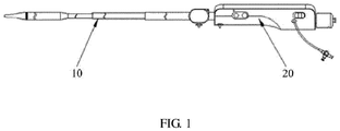
- a cardiac valve delivery system includes a delivery catheter 10 and a handle 20. A proximal end of the delivery catheter 10 is connected to the handle 20.
- the delivery catheter 10 includes an inner tube assembly 11 and an outer tube assembly 12.
- a relative movement between the inner tube assembly 11 and the outer tube assembly 12 can be achieved by the operation on handle 20.
- a cavity is axially defined in the outer tube assembly 12, and the inner tube assembly 11 can move relative to the outer tube assembly 12 in the cavity along an axial direction to cause a displacement.
- the inner tube assembly 11 includes an inner core tube 111, an inner tube 112, a conical head 114, and a fixing head 115.
- a distal end of the inner core tube 111 is connected to a proximal end of the conical head 114, a proximal end 15 of the inner core tube 111 is connected to the handle, the inner tube 112 sleeves over the inner core tube 111, and a distal end of the inner tube 112 is connected to the fixing head 115, and a proximal end of the inner tube 112 is connected to the handle.
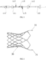
- a valve 30 is detachably connected to the fixing head 115 through a structure such as a stent. During delivery, the valve 30 is accommodated in an annular cavity formed between the inner core tube 111 and the outer tube assembly 12.
- the inner core tube 111 and the inner tube 112 are made of a polymer material and respectively formed by weaving.
- the materials used at the distal end and the proximal end of the inner tube 112 may be different.
- a relatively flexible material may be used at the distal end of the inner tube 112, so that the distal end can more easily pass through an aortic arch, while a relatively hard material may be used at the proximal end of the inner tube 112 to improve an overall tensile and/or compressive property of the inner tube 112.
- the proximal end of the inner tube 112 may be further connected to a metal reinforcing tube 113. It may be understood that, the metal reinforcing tube 113 also sleeves over the inner core tube 111, and a proximal end of the metal reinforcing tube 113 is connected to the handle.
- the outer tube assembly 12 includes a stent segment sheath 121 capable of accommodating the valve 30 and includes a delivery segment outer tube 122 connected to a proximal end of the stent segment sheath 121. It may be understood that, to increase an accommodation space between the inner core tube 111 and the stent segment sheath 121 to better accommodate the valve 30, a diameter of the inner core tube 111 is slightly less than a diameter of the inner tube 112, and a diameter of the stent segment sheath 121 is greater than a diameter of the delivery segment outer tube 122, so that a cavity for accommodating the valve 30 can be formed.
- the conical head 114 is designed to be streamlined for achieving better traceability.
- the proximal end of the conical head 114 extends into the stent segment sheath 121 from an opening at a distal end of the stent segment sheath 121, to minimize a flaring formed by an end surface of the distal end of the stent segment sheath 121 and the conical head 114 when the stent segment sheath 121 passes through the aortic arch.
- a clamping groove is defined on the fixing head 115, so that a lug 31 of the valve 30 is clamped in the clamping groove to achieve a good axial limiting.
- the stent of the valve 30 can slide relative to the stent segment sheath 121 by sliding the inner tube 112.
- the valve 30 expands and results in that the lug 31 of the valve 30 is no longer clamped in the clamping groove, so that the valve 30 is detached and deployed from the fixing head 115.
- a step structure 116 is disposed at one end of the fixing head 115 connected to the inner core tube 111 for transition.
- An outer diameter of the step structure 116 is designed to a size matching an inner diameter of the valve that is compressed and held, so that the valve can be supported and prevented from twisting.
- the valve 30 when the proximal end of the conical head 114 is received in the distal end of the stent segment sheath 121, the valve 30 is completely accommodated in the stent segment sheath 121, and a proximal end of the fixing head 115 abuts against the proximal end of the stent segment sheath 121 and is accommodated in the stent segment sheath 121. In some other embodiments, there may be a gap between the proximal end of the fixing head 115 and the proximal end of the stent segment sheath 121.
- the valve 30 is completely accommodated in the cavity between the inner core tube 111 and the stent segment sheath 121, and a case in which the service life is affected because the fixing head 115 abuts against a tube wall of the proximal end of the stent segment sheath 121 for a long time is prevented.
- the proximal end of the fixing head 115 and the proximal end of the stent segment sheath 121 may be designed as arc-shaped transition sections having matching shapes.
- a developing ring 117 is disposed on the inner core tube 111.
- the exposed developing ring 117 out of the opening at the distal end of the stent segment sheath 121 can be observed through a developing device, to observe a relative position between the inner core tube 111 and the stent segment sheath 121.
- a relative installation position of the proximal end of the valve 30 with the developing ring 117 is predetermined, so that when the developing ring 117 is exactly located at the opening at the distal end of the stent segment sheath 121 and observed, a degree at which the valve 30 is deployed from the distal end of the stent sheath can be determined.
- a distance between the proximal end of the valve 30 and the developing ring 117 is half of an axial length of the valve 30, and when the developing ring 117 moves to the opening at the distal end of the stent segment sheath 121 and is observed, it may be determined that the degree at which the valve 30 is deployed from the distal end of the stent segment sheath 121 is exactly half of the degree of a complete deploy.
- the distance between the developing ring 117 and the proximal end of the valve 30 is 1/4 of the axial length of the valve 30.
- the valve 30 is deployed from the stent segment sheath 121 by 3/4. In this way, most of the valve 30 can be deployed to observe a deploy effect.
- a driving mechanism is disposed in the handle 20, to drive the inner tube assembly 11 to axially move relative to the outer tube assembly 12.
- the driving mechanism may provide a manual or electric drive, or a manual and electric hybrid drive.
- a hybrid drive is currently used as an example to further describe the driving mechanism.
- an electric part of the driving mechanism includes a motor 24 and a screw rod 26 linked with an output shaft of the motor 24.
- the screw rod 26 screw-drives a moving member 27, so that the moving member 27 drives a delivery segment outer tube 122 fixedly connected to the moving member 27 to axially move relative to the metal reinforcing tube 113 of the inner tube assembly 11.
- a control module 25 for controlling the motor 24 is disposed on the handle 20.
- a manual knob 28 is linked with the screw rod 26 through gear engagement or in another manner, so that the moving member 27 can also move along the screw rod 26 by means of the manual knob 28.
- the moving member 27 may be connected to a proximal end of the delivery segment outer tube 122 through an outer tube fixing seat 22.
- the metal reinforcing tube 113 is fixed in the handle 20 through an inner tube fixing seat 23.
- the fixing seat 23 may be fixed in a recess on a housing of the handle 20 through clamping or in another manner, so that the entire inner tube assembly 11 is fixed relative to the handle 20.
- a stabilization tube assembly 13 for the outer tube assembly 12 to pass through is installed at a front end of the handle 20 through a stabilization tube fixing seat 21.
- the stabilization tube fixing seat 21 may be fixed in the handle 20 through clamping or welding or in another manner, to support the entire delivery system, thereby facilitating delivery of the delivery system and improving deploy stability of the valve 30.
- the stabilization tube assembly 13 includes a stabilization tube 131 and a stabilization tube round head 132 located at a distal end of the stabilization tube 131.
- a connection between the stabilization tube round head 132 and the stabilization tube 131 may be a fixed connection through hot melting or the like.
- the stabilization tube round head 132 achieves a smooth transition between the stabilization tube 131 and the delivery segment outer tube 122 of the outer tube assembly 12 to avoid scratching a blood vessel wall.
- the stabilization tube 131 is arranged to pass through a guide sheath 141 of an inline delivery catheter sheath 14 in advance, and the inline delivery catheter sheath 14 is arranged to move toward the distal end along the stabilization tube 131 until a distal end of the guide sheath 141 abuts against the root of the proximal end of the stent segment sheath 121.
- the stabilization tube 131 Under the control of a sheath core 142, the stabilization tube 131 as well as the inner tube assembly 11 and the outer tube assembly 12 which are inside the stabilization tube 131 is bent with the guide sheath 141, and the valve delivery system enters the human body from a puncture port.
- the stent segment sheath 121 is made of a high-strength polymer material, so that the stent segment sheath 121 has relatively high pressure resistance, thereby ensuring that when the valve 30 is retrieved into the stent segment sheath 121in the human body from an incompletely deployed status, the stent segment sheath 121 is not deformed by extrusion.
- the stent segment sheath 121 is formed by coating a polymer coating on a surface of a metal reinforced sheath 1211, to improve a tensile and/or compressive property of the stent segment sheath 121.
- an elastic extension section 1212 is disposed at a distal end of the metal reinforced sheath 1211. When the valve 30 is deployed, the elastic extension section 1212 may perform adaptable elastic expansion, which also facilitates retrieval of the valve 30.
- the metal reinforced sheath 1211 has a hollow structure with reinforcing ribs, to achieve that the metal reinforced sheath 1211 has a relatively high tensile and/or compressive property and can be bended flexibly as well. It may be understood that, a specific configuration of the reinforcing ribs of the hollow structure may be correspondingly adjusted based on flexibility required by the metal reinforced sheath 1211. As shown in FIG. 11 , a main body of the metal reinforced sheath 1211 has a hollow structure with spiral reinforcing ribs. In other words, a spiral part not hollowed is formed on the metal reinforced sheath 1211, the part forms the spiral reinforcing ribs, and the remaining part is formed with hollow slots distributed evenly.
- the main body of the metal reinforced sheath 1211 may alternatively have a hollow structure with straight reinforcing ribs.
- a straight part not hollowed is formed on the metal reinforced sheath 1211, the part forms the straight reinforcing ribs, and the remaining part is formed with hollow slots distributed evenly.
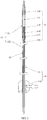
- the delivery segment outer tube 122 includes a polymer tube 1221 and a hollow tubular structure 1222 (for ease of understanding, herein, only a part of the polymer tube 1221 is shown and the hollow tubular structure 1222 is exposed).
- the hollow tubular structure 1222 is disposed at one end of the polymer tube 1221 near the stent segment sheath 121.
- the delivery segment outer tube 122 further includes a metal braided tubular structure (not shown). The metal braided tubular structure and the hollow tubular structure 1222 are both disposed in a tube wall of the polymer tube.
- the metal braided tubular structure is disposed in the entire delivery segment outer tube 122, and the hollow tubular structure 1222 is disposed only in a segment of the delivery segment outer tube 122 near the stent segment sheath 121.
- the polymer tube 1221 includes a first segment and a second segment.
- the hollow tubular structure 1222 is disposed in the first segment. Hardness of a material of the second segment is higher than that of the first segment. In this way, a segment including the hollow tubular structure has a better tensile and bending property, and overall connection strength of the delivery segment outer tube 122 is improved.
- the hollow tubular structure 1222 is a hollow structure cut from a metal tube.
- the hollow structure includes a plurality of axially spaced hollow portions 12221.
- a connection portion 12222 is formed between adjacent hollow portions 12221.
- the hollow portions 12221 are disposed circumferentially on the metal tube.
- the hollow portions 12221 and the connection portions 12222 are disposed in parallel.
- connection portions can be bent towards each other with a connection to the connecting ribs. It may be understood that, there are an even number of hollow slots; in other words, there are also an even number of connecting ribs spaced by the hollow slots.
- the hollow portion 12221 includes a plurality of connecting ribs 12221a for connecting adjacent connection portions 12222, and the hollow portion 12221 further includes a plurality of W-shaped hollow slots.
- the W-shaped hollow slots and the connecting ribs 12221a are spaced circumferentially on the hollow tubular structure 1222.
- axially adjacent W-shaped hollow slots and connecting ribs 12221a are axially staggered.
- projections of axially adjacent W-shaped hollow slots on a same vertical projection plane do not completely overlap, and projections of axially adjacent connecting ribs 12221a on a same vertical projection plane do not completely overlap.
- axially adjacent connecting ribs 12221a are two connecting ribs 12221a closest to two ends of the connection portion 12222 along an axial direction of the hollow tubular structure 1222.
- the hollow slots in the hollow portion 12221 may also be linear.
- the hollow portion has two opposite connecting ribs 12221a in the circumferential direction.
- adjacent connection portions 12222 may rotate by a particular angle about an axis defined by a line connecting the two connecting ribs 12221a, so that the hollow tubular structure 1222 can be axially bent.
- This hollow structure not only satisfies a requirement on tensile and/or compressive property of the delivery segment outer tube 122, but also enables the delivery segment outer tube 122 to have a very good bending property, thereby reducing movement during deploy of the valve 30 and improving the stability in deploy of the valve 30.
- the delivery segment outer tube 122 having the hollow structure would be subject to a particular bending deformation after entering the ascending aorta, and since the proximal end of the delivery segment outer tube 122 is in contact with and supported by a blood vessel wall, the stent segment sheath 121 and an annular root plane of the valve 30 can maintain coaxiality by adjusting the handle 20, to improve deploy effect of the valve 30.
- lines connecting two connecting ribs 12221a on hollow portions 12221 at two ends of each connection portion 12222 are parallel to each other.
- the connection portions 12222 forming the hollow tubular structure 1222 rotate in a same plane, and are bent in a two-dimensional plane, so that an adjustment requirement for maintaining the coaxiality between the stent segment sheath 121 and the annular root plane of the valve 30 can be satisfied. It may be understood that, in the circumferential direction of the connection portion 12222, there is an angle between the lines connecting the two connecting ribs 12221a of the hollow portions 12221 at the two ends of each connection portion 12222. Specifically, referring to both FIG. 14 and FIG.
- each hollow portion 12221 has two hollow slots. Projections of a line W1 connecting two opposite connecting ribs 12221a at one end of the connection portion 12222 and of a line W2 connecting two opposite connecting ribs 12221a at the other end of the connection portion 12222 on a cross section C of the connection portion 12222 intersect each other. To be specific, adjacent connection portions 12222 are respectively bent about different rotation axes W1 and W2. Because the connection portions 12222 are bent in different directions, the hollow tubular structure 1222 including the plurality of connection portions 12222 can be bent toward a plurality of directions.
- the hollow tubular structure 1222 can be bent in any direction in a three-dimensional space, so that the stent segment sheath 121 connected to the distal end of the delivery segment outer tube 122 can very easily pass through the aortic arch, and the adjustment requirement for maintaining the coaxiality between the stent segment sheath 121 and the annular root plane of the valve 30 is satisfied, thereby improving the effect in deploy of the valve 30.
- connection portions 12222 when two adjacent connection portions 12222 respectively rotate about two connection lines perpendicular to each other, to be specific, projections of the connection lines W1 and W2 on the cross section C of the connection portion 12222 are perpendicular to each other, the connection portions 12222 have relatively large rotation angles toward various dimensions, so that the hollow tubular structure 1222 can achieve a larger bending effect. Therefore, the distal end of the delivery segment outer tube 122 can achieve different bending properties by adjusting spiral rotation angles of two connecting ribs 12221a about the axial direction of the hollow tubular structure 1222, so that the adjustment requirement for maintaining the coaxiality with the annular root plane of the valve 30 can be satisfied.
- the hollow portion 12221 further includes a clamping piece 12221b and a retaining groove 12221c disposed circumferentially.
- the retaining groove 12221c is a part of the W-shaped hollow slot.
- the clamping piece 12221b and the retaining groove 12221c are located on a midperpendicular of a line connecting two connecting ribs 12221a.
- the clamping piece 12221b is limited in the retaining groove 12221c in the circumferential direction of the hollow portion 12221.
- the clamping piece 12221b can move in the limiting groove 52 and has a limiting position.
- the adjacent connection portions 12222 rotate about a line connecting the two connecting ribs 12221a and when the limiting position is reached, the top of the clamping piece 12221b abuts against the bottom of the retaining groove 12221c, to effectively prevent further rotation and bending of the connection portions 12222.
- the hollow tubular structure 1222 is allowed to be bent by a particular degree, and good support is ensured.
- the clamping piece 12221b is limited in the retaining groove 12221c in the circumferential direction, which effectively prevents the connection portions 12222 from twisting in the circumferential direction when the hollow tubular structure 1222 is bent, thereby preventing the connection portions 12222 from twisting in the circumferential direction, which causes damage to the connecting ribs 12221a and avoid impact on an effect of rotation of the connection portions 12222 about a line connecting the connecting ribs 12221a.
- the hollow tubular structure 1222 is formed by a plurality of axially interlocked metal rings. Adjacent metal rings form interlocked movable connection portions 40 at connecting end surfaces; and the adjacent metal rings are rotatable about the movable connection portions 40 to bend the hollow tubular structure 1222.
- the movable connection portion 40 is implemented as a circular notch 41 and a circular protrusion 42 opposite disposed on two end surfaces of the metal rings.
- the circular notch 41 and the circular protrusion 42 are respectively located on radially opposite circumferences of the metal rings, and a size of the circular protrusion 42 is slightly less than that of the circular notch 41.
- a bayonet 411 for clamping the root of the circular protrusion 42 is formed at an opening of the circular notch 41, and a gap 60 for adjacent metal rings to rotate around the bayonet 411 is reversed at two sides of the bayonet 411 on the end surfaces of the metal rings.
- the gap 60 can meet a requirement for a rotation space between the metal rings.
- the metal rings when a gap 60 at one side is closed by the rotation of the metal rings, the metal rings are restricted from rotating due to the abutting end surfaces of the metal rings, so that a bending degree of the hollow tubular structure 1222 can be controlled.
- the metal rings perform axial rotation around the bayonet 411. Therefore, the gap 60 may have a particular oblique angle, to be specific, increases from a near side to a far side of the bayonet 411, so that the metal rings rotate to the limiting position, and end surfaces of two metal rings defining the gap 60 can be closely attached together, as a result, the metal rings can be supported better in a bending direction, thereby improving stability of the delivery segment outer tube 122.
- a circumferential limiting portion 50 is further disposed on the end surface of the metal ring; the circumferential limiting portion 50 and the movable connection portion 40 are spaced in the circumferential direction of the metal ring; and a relative deflection angle between the circumferential limiting portion 50 and the movable connection portion 40 is 90°.
- the circumferential limiting portion 50 limits the metal rings in the circumferential direction, to improve an anti-torsion property of the metal rings, thereby preventing torsion caused by circumferential rotation from damaging stability of the movable connection portion 40.
- the relative deflection angle between the circumferential limiting portion 50 and the movable connection portion 40 in the circumferential direction of the metal ring is 90°, rotation of the metal rings around the movable connection portion 40 is not affected.
- the circumferential limiting portion 50 limits the metal ring only in the circumferential direction, and the circumferential limiting portion 50 can shrink accordingly with the rotation of the metal rings due to since the circumferential limiting portion 50 is perpendicular to the movable connection portion 40.
- a first rotation axis and a second rotation axis respectively formed from rotations of two adjacent metal rings around the bayonet 411 are parallel.
- all the metal rings are bent in a same plane.
- the hollow tubular structure 1222 can be bent and deformed in the two-dimensional plane, and the adjustment requirement for maintaining the coaxiality with the annular root plane of the valve 30 can be satisfied, thereby improving the stability in deploy of the valve 30.
- a first rotation axis and a second rotation axis respectively formed from rotations of two adjacent metal rings around the bayonet 411 have their projections on the end surfaces of the metal rings which intersect each other.
- two adjacent metal rings can rotate in different planes, so that the hollow tubular structure 1222 formed by the metal rings can be bent in at least a plurality of planes.
- the hollow tubular structure 1222 can be bent in any direction in the three-dimensional space, so that the stent segment sheath 121 connected to the distal end of the delivery segment outer tube 122 can very easily pass through the aortic arch, and the adjustment requirement for maintaining the coaxiality between the stent segment sheath 121 and the annular root plane of the valve 30 is satisfied, thereby improving the effect in deploy of the valve 30.
- rotation axes of the adjacent metal rings are perpendicular to each other, rotation angles of the metal rings in various dimensions are allowed to be relatively large in the three-dimensional space, therefore a great bend of the hollow tubular structure 1222 is achieved, thereby satisfying the adjustment requirement for maintaining the coaxiality with the annular root plane of the valve 30.
- the circumferential limiting portion 50 includes a limiting piece 51 and a limiting groove 52 whose relative deflection angles with the bayonet 411 are 90° in the circumferential direction of the metal ring.
- the limiting piece 51 is limited in the limiting groove 52 in the circumferential direction of the metal ring, and when adjacent metal rings perform relative rotation, the limiting piece 51 is movable in the limiting groove 52 and has a limiting position. At the limiting position, the top of the limiting piece 51 contacts the bottom of the limiting groove 52, to limit further relative movement of the metal rings.
- the limiting piece 51 matches the limiting groove 52, to implement good circumferential limiting to improve a circumferential anti-torsion property, thereby avoid damage to the movable connection portion 40.
- the matching between the limiting piece 51 and the limiting groove 52 does not affect rotation of the metal rings.
Landscapes
- Health & Medical Sciences (AREA)
- Life Sciences & Earth Sciences (AREA)
- Cardiology (AREA)
- Veterinary Medicine (AREA)
- General Health & Medical Sciences (AREA)
- Public Health (AREA)
- Biomedical Technology (AREA)
- Heart & Thoracic Surgery (AREA)
- Engineering & Computer Science (AREA)
- Animal Behavior & Ethology (AREA)
- Hematology (AREA)
- Anesthesiology (AREA)
- Pulmonology (AREA)
- Biophysics (AREA)
- Oral & Maxillofacial Surgery (AREA)
- Transplantation (AREA)
- Vascular Medicine (AREA)
- Prostheses (AREA)
- Media Introduction/Drainage Providing Device (AREA)
Applications Claiming Priority (2)
| Application Number | Priority Date | Filing Date | Title |
|---|---|---|---|
| CN201710682415.5A CN107496055B (zh) | 2017-08-10 | 2017-08-10 | 心脏瓣膜输送导管及输送系统 |
| PCT/CN2018/097888 WO2019029404A1 (zh) | 2017-08-10 | 2018-08-01 | 心脏瓣膜输送导管及输送系统 |
Publications (4)
| Publication Number | Publication Date |
|---|---|
| EP3666322A1 true EP3666322A1 (de) | 2020-06-17 |
| EP3666322A4 EP3666322A4 (de) | 2020-12-02 |
| EP3666322C0 EP3666322C0 (de) | 2024-02-21 |
| EP3666322B1 EP3666322B1 (de) | 2024-02-21 |
Family
ID=60689799
Family Applications (1)
| Application Number | Title | Priority Date | Filing Date |
|---|---|---|---|
| EP18842960.9A Active EP3666322B1 (de) | 2017-08-10 | 2018-08-01 | Herzklappenfreisetzungskatheter und freisetzungssystem |
Country Status (4)
| Country | Link |
|---|---|
| EP (1) | EP3666322B1 (de) |
| CN (1) | CN107496055B (de) |
| ES (1) | ES2973488T3 (de) |
| WO (1) | WO2019029404A1 (de) |
Cited By (1)
| Publication number | Priority date | Publication date | Assignee | Title |
|---|---|---|---|---|
| WO2024054735A1 (en) * | 2022-09-07 | 2024-03-14 | Stryker Corporation | Catheter having hypotubes joined by link member and method of making the same |
Families Citing this family (32)
| Publication number | Priority date | Publication date | Assignee | Title |
|---|---|---|---|---|
| CN107496055B (zh) * | 2017-08-10 | 2021-06-08 | 上海微创心通医疗科技有限公司 | 心脏瓣膜输送导管及输送系统 |
| CN109419571B (zh) * | 2017-08-25 | 2024-09-20 | 上海微创心通医疗科技有限公司 | 自膨胀假体的输送装置及自膨胀心脏瓣膜假体的输送装置 |
| CN109966023B (zh) * | 2017-12-28 | 2024-09-27 | 上海微创心通医疗科技有限公司 | 心脏瓣膜假体及其支架 |
| CN109984867B (zh) * | 2017-12-29 | 2021-05-07 | 先健科技(深圳)有限公司 | 医疗器械输送装置 |
| CN109984866B (zh) * | 2017-12-29 | 2021-05-07 | 先健科技(深圳)有限公司 | 医疗器械输送装置 |
| CN109984868B (zh) * | 2017-12-30 | 2024-08-06 | 上海微创心通医疗科技有限公司 | 心脏瓣膜假体和输送器 |
| CN110101486B (zh) | 2018-02-01 | 2024-02-27 | 上海微创心通医疗科技有限公司 | 心脏瓣膜假体及其输送器 |
| CN110160676B (zh) * | 2018-02-11 | 2021-10-26 | 上海微创电生理医疗科技股份有限公司 | 压力传感器及其电生理导管 |
| CN108742962A (zh) * | 2018-06-12 | 2018-11-06 | 北京久事神康医疗科技有限公司 | 一种支架输送系统 |
| CN110870811B (zh) | 2018-08-31 | 2025-06-17 | 上海微创心通医疗科技有限公司 | 输送装置 |
| CN111374796B (zh) * | 2018-12-27 | 2025-08-29 | 上海微创心通医疗科技有限公司 | 一种人工瓣膜的输送导管及输送装置 |
| CN111374797B (zh) * | 2018-12-27 | 2025-04-29 | 上海微创心通医疗科技有限公司 | 一种人工瓣膜的输送导管及输送装置 |
| CN111743663A (zh) * | 2019-03-29 | 2020-10-09 | 上海微创心通医疗科技有限公司 | 一种用于输送植入物的手柄及其输送系统 |
| CN110245439B (zh) * | 2019-06-20 | 2022-04-08 | 成都飞机工业(集团)有限责任公司 | 一种扩口导管的安装误差建模和补偿方法 |
| CN112438824B (zh) | 2019-09-03 | 2025-08-29 | 上海微创心通医疗科技有限公司 | 医用植入物的输送装置 |
| CN111012548B (zh) * | 2019-11-22 | 2022-06-14 | 沛嘉医疗科技(苏州)有限公司 | 一种经心尖二尖瓣输送装置 |
| CN110731844B (zh) * | 2019-11-29 | 2024-12-31 | 苏州茵络医疗器械有限公司 | 一种编织支架输送系统 |
| CN110974486A (zh) * | 2019-12-04 | 2020-04-10 | 金仕生物科技(常熟)有限公司 | 人工瓣膜输送装置 |
| CN113577519B (zh) * | 2020-04-30 | 2025-01-10 | 上海微创心通医疗科技有限公司 | 可扩张导管及可扩张导管鞘 |
| CN112914793B (zh) * | 2021-03-09 | 2022-11-15 | 金仕生物科技(常熟)有限公司 | 一种导管输送系统 |
| CN114081674B (zh) * | 2021-09-28 | 2023-08-15 | 四川大学华西医院 | 一种瓣叶分割装置 |
| CN113730037B (zh) * | 2021-09-30 | 2023-03-24 | 杭州端佑医疗科技有限公司 | 一种用于瓣膜修复的输送系统及其应用 |
| CN116035765A (zh) * | 2021-10-28 | 2023-05-02 | 上海臻亿医疗科技有限公司 | 植入物输送装置及植入物输送系统 |
| CN116158894A (zh) * | 2021-11-25 | 2023-05-26 | 应脉医疗科技(上海)有限公司 | 一种瓣膜假体的输送装置及瓣膜假体系统 |
| CN116269931A (zh) * | 2021-12-21 | 2023-06-23 | 上海微创心通医疗科技有限公司 | 输送内管、输送结构及介入手术输送系统 |
| CN114247039A (zh) * | 2022-01-21 | 2022-03-29 | 首都医科大学附属北京安贞医院 | 一种造影导管 |
| CN114404107B (zh) * | 2022-01-24 | 2025-07-11 | 科凯(南通)生命科学有限公司 | 经股动脉瓣膜输送器 |
| CN115105258B (zh) * | 2022-06-02 | 2025-05-30 | 科凯(南通)生命科学有限公司 | 含周向限位机构的心脏瓣膜输送系统 |
| CN116370153A (zh) * | 2023-04-21 | 2023-07-04 | 上海微创心通医疗科技有限公司 | 外导管、输送组件以及输送系统 |
| CN118490966A (zh) * | 2024-05-13 | 2024-08-16 | 适介医疗科技(广州)有限公司 | 一种可控弯的锚定医疗导管 |
| WO2025251989A1 (zh) * | 2024-06-06 | 2025-12-11 | 曾敏 | 人工心脏瓣膜、介入系统以及人工心脏瓣膜的位置配准方法 |
| CN118948494A (zh) * | 2024-08-05 | 2024-11-15 | 上海臻亿医疗科技有限公司 | 输送系统及其使用方法 |
Family Cites Families (19)
| Publication number | Priority date | Publication date | Assignee | Title |
|---|---|---|---|---|
| US6187034B1 (en) * | 1999-01-13 | 2001-02-13 | John J. Frantzen | Segmented stent for flexible stent delivery system |
| US7001369B2 (en) * | 2003-03-27 | 2006-02-21 | Scimed Life Systems, Inc. | Medical device |
| US20060136034A1 (en) * | 2004-12-20 | 2006-06-22 | Vascular Architects, Inc. | Delivery catheter and method |
| DE102005003632A1 (de) * | 2005-01-20 | 2006-08-17 | Fraunhofer-Gesellschaft zur Förderung der angewandten Forschung e.V. | Katheter für die transvaskuläre Implantation von Herzklappenprothesen |
| WO2009102440A1 (en) * | 2008-02-11 | 2009-08-20 | William Cook Europe Aps | Introducer for endovascular grafts and stents |
| CN102548508B (zh) * | 2009-09-21 | 2015-06-03 | 麦德托尼克公司 | 带支架的经导管假体心脏瓣膜输送系统及方法 |
| CA2779393C (en) * | 2009-11-05 | 2020-06-09 | The Trustees Of The University Of Pennsylvania | Valve prosthesis |
| US8465541B2 (en) * | 2010-04-19 | 2013-06-18 | Medtronic, Inc. | Transcatheter prosthetic heart valve delivery system and method with expandable stability tube |
| US9144665B2 (en) * | 2010-08-09 | 2015-09-29 | Boston Scientific Limited | Flexible sheath assemblies and interventional catheter systems incorporating them |
| US9155619B2 (en) * | 2011-02-25 | 2015-10-13 | Edwards Lifesciences Corporation | Prosthetic heart valve delivery apparatus |
| CN102500041B (zh) * | 2011-11-10 | 2014-11-26 | 上海微创医疗器械(集团)有限公司 | 一种球囊扩张导管 |
| CN103655004B (zh) * | 2012-09-21 | 2015-11-25 | 上海微创医疗器械(集团)有限公司 | 植入体输送系统 |
| US9433521B2 (en) * | 2012-11-27 | 2016-09-06 | Medtronic, Inc. | Distal tip for a delivery catheter |
| EP3326583B1 (de) * | 2013-05-20 | 2018-12-12 | Edwards Lifesciences Corporation | Vorrichtung zur verabreichung einer herzklappenprothese |
| CN104644288B (zh) * | 2013-11-18 | 2017-04-12 | 上海微创心通医疗科技有限公司 | 植入体的装载外管和植入体输送系统 |
| EP3131503B1 (de) * | 2014-04-17 | 2019-06-12 | Medtronic Vascular Galway | System und verfahren zur freisetzung einer transkatheter-herzklappenprothese mit scharnier |
| US10154905B2 (en) * | 2015-08-07 | 2018-12-18 | Medtronic Vascular, Inc. | System and method for deflecting a delivery catheter |
| US10350066B2 (en) * | 2015-08-28 | 2019-07-16 | Edwards Lifesciences Cardiaq Llc | Steerable delivery system for replacement mitral valve and methods of use |
| CN107496055B (zh) * | 2017-08-10 | 2021-06-08 | 上海微创心通医疗科技有限公司 | 心脏瓣膜输送导管及输送系统 |
-
2017
- 2017-08-10 CN CN201710682415.5A patent/CN107496055B/zh active Active
-
2018
- 2018-08-01 ES ES18842960T patent/ES2973488T3/es active Active
- 2018-08-01 EP EP18842960.9A patent/EP3666322B1/de active Active
- 2018-08-01 WO PCT/CN2018/097888 patent/WO2019029404A1/zh not_active Ceased
Cited By (1)
| Publication number | Priority date | Publication date | Assignee | Title |
|---|---|---|---|---|
| WO2024054735A1 (en) * | 2022-09-07 | 2024-03-14 | Stryker Corporation | Catheter having hypotubes joined by link member and method of making the same |
Also Published As
| Publication number | Publication date |
|---|---|
| ES2973488T3 (es) | 2024-06-20 |
| EP3666322C0 (de) | 2024-02-21 |
| CN107496055A (zh) | 2017-12-22 |
| CN107496055B (zh) | 2021-06-08 |
| WO2019029404A1 (zh) | 2019-02-14 |
| EP3666322A4 (de) | 2020-12-02 |
| EP3666322B1 (de) | 2024-02-21 |
Similar Documents
| Publication | Publication Date | Title |
|---|---|---|
| EP3666322B1 (de) | Herzklappenfreisetzungskatheter und freisetzungssystem | |
| US11627866B2 (en) | Method for manufacturing an endoscope insertion tube, and endoscope having an insertion tube | |
| US11864999B2 (en) | Sheath for delivering interventional instrument and sheath assembly | |
| US8376865B2 (en) | Torque shaft and torque shaft drive | |
| US9277990B2 (en) | Hypotube shaft with articulation mechanism | |
| CN112971901B (zh) | 输送鞘管和医疗器械 | |
| EP3195784A1 (de) | Biegerohr und endoskopvorrichtung mit dem biegerohr | |
| US20140235361A1 (en) | Torque Shaft and Torque Shaft Drive | |
| US10278727B2 (en) | Pericardium puncture needle assembly | |
| US11759343B2 (en) | Distal end structure of sheath for delivering interventional instrument and sheath | |
| US20230001150A1 (en) | Medical Apparatus System | |
| CN116212212B (zh) | 一种可调弯的导管及医疗器械 | |
| US20190223904A1 (en) | Pericardium puncture needle assembly | |
| US20230028589A1 (en) | Delivery sheath and medical device | |
| EP3777728B1 (de) | Medizinprodukt | |
| WO2017203582A1 (ja) | 内視鏡用デバイスおよび内視鏡システム | |
| JP7827454B2 (ja) | 医療機器 | |
| US20230414356A1 (en) | Device for heart repair | |
| CN121446006A (zh) | 用于介入治疗的逆向微导管 |
Legal Events
| Date | Code | Title | Description |
|---|---|---|---|
| STAA | Information on the status of an ep patent application or granted ep patent |
Free format text: STATUS: THE INTERNATIONAL PUBLICATION HAS BEEN MADE |
|
| PUAI | Public reference made under article 153(3) epc to a published international application that has entered the european phase |
Free format text: ORIGINAL CODE: 0009012 |
|
| STAA | Information on the status of an ep patent application or granted ep patent |
Free format text: STATUS: REQUEST FOR EXAMINATION WAS MADE |
|
| 17P | Request for examination filed |
Effective date: 20200220 |
|
| AK | Designated contracting states |
Kind code of ref document: A1 Designated state(s): AL AT BE BG CH CY CZ DE DK EE ES FI FR GB GR HR HU IE IS IT LI LT LU LV MC MK MT NL NO PL PT RO RS SE SI SK SM TR |
|
| AX | Request for extension of the european patent |
Extension state: BA ME |
|
| DAV | Request for validation of the european patent (deleted) | ||
| DAX | Request for extension of the european patent (deleted) | ||
| A4 | Supplementary search report drawn up and despatched |
Effective date: 20201029 |
|
| RIC1 | Information provided on ipc code assigned before grant |
Ipc: A61M 25/01 20060101AFI20201023BHEP Ipc: A61F 2/24 20060101ALI20201023BHEP Ipc: A61F 2/962 20130101ALN20201023BHEP |
|
| STAA | Information on the status of an ep patent application or granted ep patent |
Free format text: STATUS: EXAMINATION IS IN PROGRESS |
|
| 17Q | First examination report despatched |
Effective date: 20230124 |
|
| GRAP | Despatch of communication of intention to grant a patent |
Free format text: ORIGINAL CODE: EPIDOSNIGR1 |
|
| STAA | Information on the status of an ep patent application or granted ep patent |
Free format text: STATUS: GRANT OF PATENT IS INTENDED |
|
| RIC1 | Information provided on ipc code assigned before grant |
Ipc: A61F 2/962 20130101ALN20230828BHEP Ipc: A61F 2/24 20060101ALI20230828BHEP Ipc: A61M 25/01 20060101AFI20230828BHEP |
|
| RIC1 | Information provided on ipc code assigned before grant |
Ipc: A61F 2/962 20130101ALN20230918BHEP Ipc: A61F 2/24 20060101ALI20230918BHEP Ipc: A61M 25/01 20060101AFI20230918BHEP |
|
| INTG | Intention to grant announced |
Effective date: 20231002 |
|
| GRAS | Grant fee paid |
Free format text: ORIGINAL CODE: EPIDOSNIGR3 |
|
| GRAA | (expected) grant |
Free format text: ORIGINAL CODE: 0009210 |
|
| STAA | Information on the status of an ep patent application or granted ep patent |
Free format text: STATUS: THE PATENT HAS BEEN GRANTED |
|
| AK | Designated contracting states |
Kind code of ref document: B1 Designated state(s): AL AT BE BG CH CY CZ DE DK EE ES FI FR GB GR HR HU IE IS IT LI LT LU LV MC MK MT NL NO PL PT RO RS SE SI SK SM TR |
|
| REG | Reference to a national code |
Ref country code: GB Ref legal event code: FG4D |
|
| REG | Reference to a national code |
Ref country code: CH Ref legal event code: EP |
|
| REG | Reference to a national code |
Ref country code: IE Ref legal event code: FG4D |
|
| REG | Reference to a national code |
Ref country code: DE Ref legal event code: R096 Ref document number: 602018065642 Country of ref document: DE |
|
| U01 | Request for unitary effect filed |
Effective date: 20240311 |
|
| U07 | Unitary effect registered |
Designated state(s): AT BE BG DE DK EE FI FR IT LT LU LV MT NL PT SE SI Effective date: 20240318 |
|
| PG25 | Lapsed in a contracting state [announced via postgrant information from national office to epo] |
Ref country code: IS Free format text: LAPSE BECAUSE OF FAILURE TO SUBMIT A TRANSLATION OF THE DESCRIPTION OR TO PAY THE FEE WITHIN THE PRESCRIBED TIME-LIMIT Effective date: 20240621 |
|
| PG25 | Lapsed in a contracting state [announced via postgrant information from national office to epo] |
Ref country code: GR Free format text: LAPSE BECAUSE OF FAILURE TO SUBMIT A TRANSLATION OF THE DESCRIPTION OR TO PAY THE FEE WITHIN THE PRESCRIBED TIME-LIMIT Effective date: 20240522 |
|
| PG25 | Lapsed in a contracting state [announced via postgrant information from national office to epo] |
Ref country code: HR Free format text: LAPSE BECAUSE OF FAILURE TO SUBMIT A TRANSLATION OF THE DESCRIPTION OR TO PAY THE FEE WITHIN THE PRESCRIBED TIME-LIMIT Effective date: 20240221 Ref country code: RS Free format text: LAPSE BECAUSE OF FAILURE TO SUBMIT A TRANSLATION OF THE DESCRIPTION OR TO PAY THE FEE WITHIN THE PRESCRIBED TIME-LIMIT Effective date: 20240521 |
|
| PG25 | Lapsed in a contracting state [announced via postgrant information from national office to epo] |
Ref country code: RS Free format text: LAPSE BECAUSE OF FAILURE TO SUBMIT A TRANSLATION OF THE DESCRIPTION OR TO PAY THE FEE WITHIN THE PRESCRIBED TIME-LIMIT Effective date: 20240521 Ref country code: NO Free format text: LAPSE BECAUSE OF FAILURE TO SUBMIT A TRANSLATION OF THE DESCRIPTION OR TO PAY THE FEE WITHIN THE PRESCRIBED TIME-LIMIT Effective date: 20240521 Ref country code: IS Free format text: LAPSE BECAUSE OF FAILURE TO SUBMIT A TRANSLATION OF THE DESCRIPTION OR TO PAY THE FEE WITHIN THE PRESCRIBED TIME-LIMIT Effective date: 20240621 Ref country code: HR Free format text: LAPSE BECAUSE OF FAILURE TO SUBMIT A TRANSLATION OF THE DESCRIPTION OR TO PAY THE FEE WITHIN THE PRESCRIBED TIME-LIMIT Effective date: 20240221 Ref country code: GR Free format text: LAPSE BECAUSE OF FAILURE TO SUBMIT A TRANSLATION OF THE DESCRIPTION OR TO PAY THE FEE WITHIN THE PRESCRIBED TIME-LIMIT Effective date: 20240522 |
|
| PG25 | Lapsed in a contracting state [announced via postgrant information from national office to epo] |
Ref country code: PL Free format text: LAPSE BECAUSE OF FAILURE TO SUBMIT A TRANSLATION OF THE DESCRIPTION OR TO PAY THE FEE WITHIN THE PRESCRIBED TIME-LIMIT Effective date: 20240221 |
|
| PG25 | Lapsed in a contracting state [announced via postgrant information from national office to epo] |
Ref country code: PL Free format text: LAPSE BECAUSE OF FAILURE TO SUBMIT A TRANSLATION OF THE DESCRIPTION OR TO PAY THE FEE WITHIN THE PRESCRIBED TIME-LIMIT Effective date: 20240221 |
|
| U20 | Renewal fee for the european patent with unitary effect paid |
Year of fee payment: 7 Effective date: 20240827 |
|
| PG25 | Lapsed in a contracting state [announced via postgrant information from national office to epo] |
Ref country code: SM Free format text: LAPSE BECAUSE OF FAILURE TO SUBMIT A TRANSLATION OF THE DESCRIPTION OR TO PAY THE FEE WITHIN THE PRESCRIBED TIME-LIMIT Effective date: 20240221 |
|
| PG25 | Lapsed in a contracting state [announced via postgrant information from national office to epo] |
Ref country code: CZ Free format text: LAPSE BECAUSE OF FAILURE TO SUBMIT A TRANSLATION OF THE DESCRIPTION OR TO PAY THE FEE WITHIN THE PRESCRIBED TIME-LIMIT Effective date: 20240221 |
|
| PG25 | Lapsed in a contracting state [announced via postgrant information from national office to epo] |
Ref country code: SK Free format text: LAPSE BECAUSE OF FAILURE TO SUBMIT A TRANSLATION OF THE DESCRIPTION OR TO PAY THE FEE WITHIN THE PRESCRIBED TIME-LIMIT Effective date: 20240221 |
|
| PG25 | Lapsed in a contracting state [announced via postgrant information from national office to epo] |
Ref country code: SM Free format text: LAPSE BECAUSE OF FAILURE TO SUBMIT A TRANSLATION OF THE DESCRIPTION OR TO PAY THE FEE WITHIN THE PRESCRIBED TIME-LIMIT Effective date: 20240221 Ref country code: SK Free format text: LAPSE BECAUSE OF FAILURE TO SUBMIT A TRANSLATION OF THE DESCRIPTION OR TO PAY THE FEE WITHIN THE PRESCRIBED TIME-LIMIT Effective date: 20240221 Ref country code: RO Free format text: LAPSE BECAUSE OF FAILURE TO SUBMIT A TRANSLATION OF THE DESCRIPTION OR TO PAY THE FEE WITHIN THE PRESCRIBED TIME-LIMIT Effective date: 20240221 Ref country code: CZ Free format text: LAPSE BECAUSE OF FAILURE TO SUBMIT A TRANSLATION OF THE DESCRIPTION OR TO PAY THE FEE WITHIN THE PRESCRIBED TIME-LIMIT Effective date: 20240221 |
|
| REG | Reference to a national code |
Ref country code: DE Ref legal event code: R097 Ref document number: 602018065642 Country of ref document: DE |
|
| PLBE | No opposition filed within time limit |
Free format text: ORIGINAL CODE: 0009261 |
|
| STAA | Information on the status of an ep patent application or granted ep patent |
Free format text: STATUS: NO OPPOSITION FILED WITHIN TIME LIMIT |
|
| 26N | No opposition filed |
Effective date: 20241122 |
|
| GBPC | Gb: european patent ceased through non-payment of renewal fee |
Effective date: 20240801 |
|
| PG25 | Lapsed in a contracting state [announced via postgrant information from national office to epo] |
Ref country code: MC Free format text: LAPSE BECAUSE OF FAILURE TO SUBMIT A TRANSLATION OF THE DESCRIPTION OR TO PAY THE FEE WITHIN THE PRESCRIBED TIME-LIMIT Effective date: 20240221 |
|
| PG25 | Lapsed in a contracting state [announced via postgrant information from national office to epo] |
Ref country code: GB Free format text: LAPSE BECAUSE OF NON-PAYMENT OF DUE FEES Effective date: 20240801 |
|
| PG25 | Lapsed in a contracting state [announced via postgrant information from national office to epo] |
Ref country code: IE Free format text: LAPSE BECAUSE OF NON-PAYMENT OF DUE FEES Effective date: 20240801 |
|
| U20 | Renewal fee for the european patent with unitary effect paid |
Year of fee payment: 8 Effective date: 20250827 |
|
| PGFP | Annual fee paid to national office [announced via postgrant information from national office to epo] |
Ref country code: ES Payment date: 20250926 Year of fee payment: 8 |
|
| PGFP | Annual fee paid to national office [announced via postgrant information from national office to epo] |
Ref country code: CH Payment date: 20250901 Year of fee payment: 8 |
|
| PG25 | Lapsed in a contracting state [announced via postgrant information from national office to epo] |
Ref country code: CY Free format text: LAPSE BECAUSE OF FAILURE TO SUBMIT A TRANSLATION OF THE DESCRIPTION OR TO PAY THE FEE WITHIN THE PRESCRIBED TIME-LIMIT; INVALID AB INITIO Effective date: 20180801 |
|
| PG25 | Lapsed in a contracting state [announced via postgrant information from national office to epo] |
Ref country code: HU Free format text: LAPSE BECAUSE OF FAILURE TO SUBMIT A TRANSLATION OF THE DESCRIPTION OR TO PAY THE FEE WITHIN THE PRESCRIBED TIME-LIMIT; INVALID AB INITIO Effective date: 20180801 |