EP3666962B1 - Vorrichtung mit integrierter wäschebehandlungsfunktionalität und verfahren zum nutzen einer solchen vorrichtung - Google Patents
Vorrichtung mit integrierter wäschebehandlungsfunktionalität und verfahren zum nutzen einer solchen vorrichtung Download PDFInfo
- Publication number
- EP3666962B1 EP3666962B1 EP19213093.8A EP19213093A EP3666962B1 EP 3666962 B1 EP3666962 B1 EP 3666962B1 EP 19213093 A EP19213093 A EP 19213093A EP 3666962 B1 EP3666962 B1 EP 3666962B1
- Authority
- EP
- European Patent Office
- Prior art keywords
- carrier
- clothing
- item
- treatment
- facility
- Prior art date
- Legal status (The legal status is an assumption and is not a legal conclusion. Google has not performed a legal analysis and makes no representation as to the accuracy of the status listed.)
- Active
Links
Images


Classifications
-
- A—HUMAN NECESSITIES
- A47—FURNITURE; DOMESTIC ARTICLES OR APPLIANCES; COFFEE MILLS; SPICE MILLS; SUCTION CLEANERS IN GENERAL
- A47B—TABLES; DESKS; OFFICE FURNITURE; CABINETS; DRAWERS; GENERAL DETAILS OF FURNITURE
- A47B61/00—Wardrobes
-
- A—HUMAN NECESSITIES
- A47—FURNITURE; DOMESTIC ARTICLES OR APPLIANCES; COFFEE MILLS; SPICE MILLS; SUCTION CLEANERS IN GENERAL
- A47B—TABLES; DESKS; OFFICE FURNITURE; CABINETS; DRAWERS; GENERAL DETAILS OF FURNITURE
- A47B61/00—Wardrobes
- A47B61/02—Wardrobes with extensible garment-holders
-
- A—HUMAN NECESSITIES
- A47—FURNITURE; DOMESTIC ARTICLES OR APPLIANCES; COFFEE MILLS; SPICE MILLS; SUCTION CLEANERS IN GENERAL
- A47B—TABLES; DESKS; OFFICE FURNITURE; CABINETS; DRAWERS; GENERAL DETAILS OF FURNITURE
- A47B95/00—Fittings for furniture
-
- A—HUMAN NECESSITIES
- A47—FURNITURE; DOMESTIC ARTICLES OR APPLIANCES; COFFEE MILLS; SPICE MILLS; SUCTION CLEANERS IN GENERAL
- A47B—TABLES; DESKS; OFFICE FURNITURE; CABINETS; DRAWERS; GENERAL DETAILS OF FURNITURE
- A47B97/00—Furniture or accessories for furniture, not provided for in other groups of this subclass
-
- D—TEXTILES; PAPER
- D06—TREATMENT OF TEXTILES OR THE LIKE; LAUNDERING; FLEXIBLE MATERIALS NOT OTHERWISE PROVIDED FOR
- D06F—LAUNDERING, DRYING, IRONING, PRESSING OR FOLDING TEXTILE ARTICLES
- D06F58/00—Domestic laundry dryers
- D06F58/10—Drying cabinets or drying chambers having heating or ventilating means
- D06F58/12—Drying cabinets or drying chambers having heating or ventilating means having conveying means for moving clothes, e.g. along an endless track
-
- D—TEXTILES; PAPER
- D06—TREATMENT OF TEXTILES OR THE LIKE; LAUNDERING; FLEXIBLE MATERIALS NOT OTHERWISE PROVIDED FOR
- D06F—LAUNDERING, DRYING, IRONING, PRESSING OR FOLDING TEXTILE ARTICLES
- D06F73/00—Apparatus for smoothing or removing creases from garments or other textile articles by formers, cores, stretchers, or internal frames, with the application of heat or steam
- D06F73/02—Apparatus for smoothing or removing creases from garments or other textile articles by formers, cores, stretchers, or internal frames, with the application of heat or steam having one or more treatment chambers
Definitions
- the present invention relates to a device with integrated laundry treatment functionality and a method for using such a device.
- Cabinets are known in which a laundry treatment functionality is integrated and with which z. B. can automatically iron a shirt hanging in the closet. Further examples of such cabinets are marketed by the companies SWASH® , Effie® or LG® (as LG Styler).
- such laundry treatment cabinets can freshen, dry, scent and/or iron the garments placed therein.
- creases are to be removed here.
- different methods are used to stretch the shirt, e.g. B. inflating a stuck in the shirt textile or ironing dummy with warm air.
- a gas and/or air stream flows around the items of clothing in order to freshen up and/or dry the item of clothing.
- the KR 2010 0099431 A deals with a laundry treating apparatus in which the air is agitated by moving the clothes inside, so that moisture or hot air can be supplied to the clothes evenly.
- the DE 10 2007 033912 A1 discloses a tunnel finisher for treating items of clothing with superheated steam and hot air, the hot air being guided along the items of clothing not only transversely to the transport direction, but also countercurrently to the transport direction.
- the EP 3 294 944 A1 discloses a tumble dryer with electrodes that generate an electric field in the interior for drying.
- a sensor unit monitors the laundry and the position of the electrodes and intervals between the laundry items can be adjusted.
- the KR 2016 0028798 A describes a cabinet with two separable spaces for treating laundry. Laundry can be moved back and forth between the rooms by means of a motor.
- the WO 2017/018777 A1 describes a multifunctional clothes washing device in which clothes can be pushed aside and pressed together by a movable element.
- the JP 2002 000997 A describes a tumble dryer in a storage container, in which the air access to the laundry items is to be improved by swinging the laundry up and down and back and forth.
- the JP 2002 136798 A describes an apparatus for drying, deodorizing and sterilizing clothes.
- the items of clothing are hung on a rail and moved on an orbit and rotated in the process.
- a device with integrated laundry treatment functionality in particular a piece of laundry treatment furniture for domestic use, wherein in an operating state in the device a first item of clothing and/or a second item of clothing is subjected to a treatment, the device having a first carrier for holding the first item of clothing and at least one second carrier for holding a second item of clothing, the device being designed in such a way that an actuator device creates a distance between the first carrier and the second carrier for exposing at least one side of the first item of clothing and/or a The distance between the first carrier and a wall side of the device for exposing at least one side of the first piece of clothing is or can be changed.
- the object according to the invention is configured in such a way that at least one side of the first garment can be exposed and then subjected to an individual treatment.
- the device according to the invention allows the first and second items of clothing to be treated in stages, with at least one side of the first item of clothing is exposed in such a way that, for example, a gas or air flow can be guided past the side of the first item of clothing.
- the first piece of clothing or the second piece of clothing is then preferably arranged by means of the first carrier and the second carrier in such a way that a free space advantageous for the treatment is provided within a first partial area, while no treatment takes place in at least a second partial area and the second ones located here Garments can be placed immediately adjacent to each other.
- the total installation space required within the device can be limited, since a corresponding free space does not have to be provided between all the first and second items of clothing.
- the first partial area preferably comprises a free space which forms a channel along which a gas or air flow can be guided.
- the gas or air flow can be introduced by means of a treatment device in a targeted manner into the first partial area, in particular into the free space forming the channel.
- the treatment device preferably comprises a line or a line system.
- the temperature of the gas or air flow can preferably be controlled or mixed with fragrances, aerosols and/or ozone in order to develop a specific effect on the first or second item of clothing.
- the treatment device has a heating device and/or a cooling device as well as a device for mixing the gas or air flow with a fragrance or aerosol.
- the first carrier and the second carrier are preferably driven to perform different movements with a common actuator device in order to bring about the desired alignment of the first and the second article of clothing.
- the first carrier and/or the second carrier each have their own actuator device, for example a Servo motor to be driven.
- the advantage here is that the individual positions can be approached as desired and they do not necessarily have to be adjacent to one another. Examples of items of clothing are trousers, shirts, coats and/or dresses. However, a bag with loosely collected pieces of textile is also to be understood as a piece of clothing.
- the device is a laundry treatment piece of furniture, in particular a laundry treatment cabinet or chest of drawers.
- the device includes a door or flap with which the device can be opened and closed. This gives the user access to the interior of the device in order to hang the first carrier/second carrier there, for example on a rail, in particular without stepping onto the device.
- the first carrier and/or the second carrier are designed in particular as a bracket.
- the first and/or second carrier is positioned in such a way that a channel for guiding the gas or air flow is formed, the width of which is at least 5 cm, preferably at least 6.5 cm or more preferably more than 7.5 cm.
- the main plane of extension is defined by the orientation of the first item of clothing or the second item of clothing, which essentially extends flatly in the suspended state.
- the device has a rail along which the first carrier and the second carrier are arranged to be displaceable.
- the first carrier and every second carrier is moved at least once within a cycle. Due to the displaceable mounting on the rail, the first carrier and the second carrier can be displaced relative to one another in the longitudinal direction of the rail, so that the corresponding required distance between the first and second carrier can be realized.
- this displacement takes place in an automated manner, preferably fully automated, and is synchronized with the treatment cycle of the respective first or second item of clothing, ie the at least one side of the first item of clothing is first exposed and then subjected to the treatment.
- a further movement of the first and/or second wearer then either exposes the other side of the first item of clothing or the second item of clothing is exposed, so that subsequent to the new positioning, further treatment can take place here, in particular a further treatment of the other side of the first garment or one side of the second garment.
- This can be continued until all items of clothing that are arranged within the device have been released accordingly and then treated.
- both the first carrier and the second carrier are moved in order to release the respective element.
- first wearer and/or second wearer are moved in the direction of the second partial areas in such a way that they press the items of clothing arranged in the second partial area together to create the necessary free space for the treatment of at least one side of the first item of clothing in the first to provide space.
- the first carrier and the second carrier can each be driven or are driven by an actuator device or by a common actuator device.
- an individual actuator device for example an individualized motor, in particular a servomotor, would advantageously the repair or maintenance work simplified, since usually only a single element of the actuator device has to be removed.
- the individual actuator device ensures here that the respective carrier is moved back and forth.
- the actuator device preferably acts on a fastening element or a hanger, on which in turn the first carrier or the second carrier can be detachably mounted. It is conceivable that the adjacent fastening elements or hangers or the end of the rail act as a dynamic stop.
- this actuator device preferably includes an element for coordinating the individual fastening elements, on which in turn the first carrier or the second carrier is mounted.
- the element for coordination is a gear with which the respective position of the individual fastening elements is clearly defined during a cycle. By moving the gear, it is then advantageously possible to establish a specific alignment of the individual fastening elements and thus of the first carrier and/or the second carrier. In comparison to the isolated drive of the individual fastening elements, this is technically less complicated and is therefore particularly preferred. Provision is preferably made for the first carrier and/or second carrier to comprise an ironing dummy, for example various inflatable chambers. However, it is also conceivable for the first carrier and/or the second carrier to be designed as a clamping frame.
- the actuator device for aligning the first carrier and/or the second carrier has a link guide for the lateral offset of the first carrier and/or the second carrier.
- a link guide can be used to provide a simple means for coordinating the respective position of the fastening elements.
- the respective fastening elements engage with their engagement area preferably in a groove and the link with its groove is moved at least temporarily during operation and the course of the link offsets the engagement area of the fastening element following the course of the respective link. It is conceivable that the
- Link guide is interchangeable, that is, the respective courses of the individual scenes, which are each provided for the individual fastener can be changed if you want to change the timing and / or the lateral alignment of the individual fasteners to each other.
- the actuator device is a fastening element, d. H. a suspension
- the fastening element has an interface area for coupling the first carrier and/or the second carrier to the fastening element and an engagement area for engaging in a groove or groove of the link guide.
- the interface area permits the detachable and/or replaceable assembly of the first carrier and the second carrier on the fastening element.
- the interface is designed as a hook or eyelet or something similar, in which the hook of the first carrier and/or second carrier, which is designed as a bracket, for example, can be hung.
- the interface area is equipped in such a way that it prevents the first and/or second item of clothing or the first and/or second carrier from twisting during the movement in the longitudinal direction of the rail.
- a hook of the first carrier or of the second carrier is fixed between two plate-shaped elements.
- the engagement area is designed as a pin element which engages in the correspondingly assigned groove of the connecting link.
- the link guide is preferably part of a rotating body and/or a translation body.
- the link guide is arranged on the outside of a roller, i.e. a rotary body, so that when the rotary body or roller rotates, the groove of the link guide moves relative to the engagement areas of the fastening elements and a lateral offset in the longitudinal direction of the rail can thus be caused .
- the link guide is embedded in a plate that moves laterally or diagonally (e.g perpendicular to the longitudinal direction of the rail) relative to the rail to cause the engaging portions disposed in the respective grooves to move laterally along the longitudinal direction of the rail.
- the design as a rotary body proves to be particularly space-saving and the rotary body can be driven to rotate particularly easily by a motor mounted on the front side.
- the connecting link guide has a section that includes a periodic curve, for example a sinusoidal curve, for moving the first item of clothing back and forth during the treatment.
- a periodic curve for example a sinusoidal curve
- the first piece of clothing cannot be rigidly aligned during the treatment by means of the connecting link guide, but is guided back and forth within the free space.
- the link guide is moved back and forth, i. H. the motor changes its direction of rotation or drive direction, for example, or the link guide has a meandering or sinusoidal course, at least in sections.
- the movement improves the air dynamics during the treatment, which means that dead areas on the first piece of clothing that are poorly treated or not treated as a result of flow shadowing that would otherwise occur can be avoided.
- the actuator device has a carriage element which is mounted on the rail of the device in a displaceable manner in the longitudinal direction of the rail and through which the fastening element preferably reaches.
- the stability of the fastening element during the individual movements can be increased by mounting it on the carriage element, which is preferably adapted to a corresponding guide of the rail.
- the carriage element is made of a rubber element and / or a plastic, with which the fastener can also be slightly inclined, so as to avoid tilting in the respective link or link guide.
- the device comprises a treatment device which uses a gas or Air flow provides, the treatment device is designed such that it adjusts an orientation of the gas or air flow depending on the position of the exposed side of the first garment. Due to the successive treatment of the individual items of clothing arranged next to one another, the free-standing area shifts from one side of the wall of the device to the opposite side of the wall during the cycle. Accordingly, it is provided that the treatment device takes this into account and generates or causes the air or gas flow only in the areas in which the currently exposed side of the first or second item of clothing can actually be found.
- the actuator device is preferably a simple single-phase synchronous geared motor with at least one reference sensor and a time-controlled or monitored position of the rotary body, a stepping motor (BLDC motor) with a predetermined position and at least one defined reference.
- BLDC motor stepping motor
- any other analog drive is also conceivable as an actuator device, with at least one sensor that registers the position of the gear or the connecting link.
- the actuator device is operated continuously.
- all fastening elements are moved continuously and simultaneously, in particular permanently (over a period of time that exceeds the treatment period), by the rotating body being caused to rotate uniformly and continuously, for example.
- This can be implemented in a comparatively simple manner with a single-phase synchronous motor.
- the transmission or the link guide is designed in such a way that all the fastening elements are permanently, ie always, in motion and their speed particularly preferably changes continuously.
- phase-shifted sine curves are conceivable as backdrops for the backdrop guide.
- the actuator device transfers the gate into a position in which there is a fixed distance between the first and/or the second carrier or the wall side. This position is then retained during the treatment. Only after the treatment has been completed is the actuator device caused to move again, which causes the first and/or second carrier to be displaced laterally in the longitudinal direction of the rail.
- the first and/or second item of clothing undergoes an individually adapted treatment and corresponding parameters are set for this purpose.
- parameters are time, temperature, type of treatment such as e.g. B. the type and amount of additives, and / or the flow rate.
- the backdrop provides a corresponding shape that ensures the corresponding waiting time of the first or second item of clothing for treatment in the first partial area.
- the motor can preferably also be controlled in such a way that the desired waiting times are set. As a result, the treatments for the individual items of clothing can be set individually in an advantageous manner.
- the position or orientation of the link guide is used to control the parameters to be set in each case. i.e. the parameters are defined, set or changed depending on the alignment of the link guide.
- the choice of parameters is preferably adapted to the respective type of item of clothing, for example the set of parameters differs from that for a coat and that for a shirt.
- a first item of clothing 21 is shown in the form of a shirt.
- the first item of clothing 21 is arranged on a first carrier 31, for example a hanger.
- the first carrier 31 With the first carrier 31, the first item of clothing 21 can be placed in a device 1 with integrated laundry treatment functionality.
- the first carrier 31 has a hook for this purpose, which can be hung on a corresponding rail 7 in the device 1 with integrated laundry treatment functionality.
- the first item of clothing 31 can be subjected to a treatment when hung in the device 1 with the integrated laundry treatment functionality.
- the gas or air flow can be mixed with fragrances or aerosols, with which the first item of clothing 21 can be freshened up in an advantageous manner.
- the gas or air flow is tempered, ie cooled or heated, and is then guided past the first item of clothing 21 in the tempered state.
- the device 1 with integrated laundry treatment functionality comprises a treatment device, which for example has a line system for guiding the gas or air flow, a heating and/or cooling device for tempering the gas or air flow, a reservoir with a fragrance and/or nozzle-like outlet openings , with which the gas or air flow can be aimed specifically at the first item of clothing 21 .
- the first item of clothing 21 forms an essentially two-dimensional object which extends along a main plane of extension HSE.
- a thickness B1 of the first item of clothing 21 measured perpendicular to the main extension plane HSE can then be 20 cm, for example. It has proven to be advantageous for optimal treatment of the first item of clothing 21 if the gas or air flow is provided on each side S of the first item of clothing 21 with a free space whose width B2 perpendicular to the main plane of extent HSE is at least 5 cm. As a result, a channel 9 for the gas or air flow is provided which is uniform or homogeneous treatment of the first item of clothing 21 on both sides S ensures.
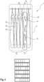
- FIG 2 a device 1 with integrated laundry treatment functionality is illustrated, in which further second items of clothing 22 are arranged next to the first item of clothing 21 .
- the device 1 is a piece of furniture designed for domestic use.
- the device 1 comprises a housing 3 and, in the upper section of the housing 3, a rail 7 to which the first carrier 31 and the plurality of second carriers 32 can be detachably fastened. Furthermore, it is preferably provided if the device 1 can be closed, for example by means of a door, flap or a roller blind.
- the first items of clothing 21 and second items of clothing 22 arranged next to one another within the housing 3 must each be kept at a distance here so that a sufficiently large channel 9 for guiding the gas or air flow is formed between them.
- a device 1 with integrated laundry treatment functionality according to a preferred first embodiment of the present invention is shown in the upper half. It is provided here that the device 1 is configured or designed such that the first carrier 31 and/or the second carrier 32 is automatically moved along a longitudinal direction L of the rail 7 by means of one or more actuator devices 40 . In particular, the movement or shifting in the longitudinal direction L of the rail 7 is dimensioned or coordinated in such a way that the first item of clothing 21 is released.
- the first carrier 31 is accordingly aligned or positioned with a gas or air flow in such a way that the required free space for the formation of the desired channel 9 is formed on both sides S of the first item of clothing 21 . After the positioning of the first garment 21, the treatment for the first garment 21 is then started.
- a treatment is carried out within the device 1 only in a first partial area T1.
- the gas or air flow passes both sides S of the first garment 21 and one side S of the adjacent second garments 22. While the treatment takes place in the first partial area T1, the second garments 22 remain the same in a second partial area T2 time untreated.
- the distance between the second items of clothing 22 among one another or between the second item of clothing 22 and one of the wall sides of the housing 3 can be reduced. Consequently, the desired spacing between all garments is not required in the device 1 with the integrated laundry treatment functionality.
- the device 1 can be dimensioned smaller, in particular in a direction perpendicular to the main extension plane HSE of the suspended first items of clothing 21 or second items of clothing 22 or parallel to the longitudinal direction L of the rail 7.
- Another advantage of the in figure 3 illustrated embodiment is that each side S of the first garment 21 and the second garments 22 is subjected to a treatment twice.
- the treatment device In order to ensure the respective treatment by means of the treatment device at the respective variable positions in the device, provision is preferably made for the treatment device to be shifted, in particular into the current first partial area T1 in which the first item of clothing is being treated. Alternatively, it is also conceivable for the treatment device to extend over the entire length of the first items of clothing 21 and second items of clothing 22 arranged next to one another and for the gas or air flow to be selectively let out only in the first partial area T1 by means of valves and/or closure flaps.
- FIG 4 the device 1 with integrated laundry treatment functionality according to a second preferred embodiment of the present invention is shown in the upper half.
- the first carrier 31 and the second carrier 32 is moved by means of one or more actuators.
- the embodiment differs from that of FIG figure 3 that through the movement of the first carrier 31 and the second carrier 32 only one side S of the first item of clothing 21 and only one side S of the first item of clothing 21 facing the second item of clothing 22 are exposed.
- only a single narrow channel 9 for the gas or air flow is formed in a direction running perpendicularly to the main extension plane HSE.
- an actuator device 40 for displacing the first carrier 31 and the second carrier 32 is shown as an example.
- the actuator device 40 is arranged above the rail 7 .
- the rail 7 is designed for the storage of fastening elements 43, to which in turn the first carrier 31 and/or second carrier 32 can be fastened.
- a carriage element 45 is provided, on which the fastening element 43 is mounted and/or through which the fastening element 43 extends.
- the fastening element 43 then has an interface 41 for receiving or for coupling the first carrier 31 or the second carrier 43 to the respective fastening element 43 on a side facing away from the actuator device 40 .
- the fastening elements 43 have, for example, on their side facing away from the actuator device 40, a hook and/or an eyelet, to which the first carrier 31 and/or second carrier 32 can be fastened.
- the fastening element 43 has a pin-shaped end on a side facing the actuator device 40 .
- the carriage element 45 is in turn movably mounted in the longitudinal direction L of the rail 7 .
- the rail 7 has, for example, corresponding elongated holes or an elongated hole.
- the actuator device 40 is designed as a rotary body 50 or roller, which can be driven by a motor 49 to rotate about an axis of rotation R.
- the rotary body 50 has grooves or grooves 47 on its outer circumference, which serve as a link guide for the pin-shaped ends of the fastening element 43 .
- the pin-shaped end forms an engagement area 42 of the fastening element 43 or the suspension.
- the grooves 47 running around the rotating body 50 in the circumferential direction are designed in such a way that their course has an axial component at least in certain areas.
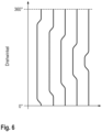
- FIG. 12 is an example of the course of the connecting link guide for an actuator device 40 figure 5 shown.
- the respective course of the grooves is shown in relation to the angle of rotation of the rotary body 50 for five different grooves or grooves 47 .
- the course of the connecting link is designed in such a way that the first carrier 31 and the second carrier 32 are successively shifted to one side.
- the first carrier 31 or all of the second carriers 32 are shifted by the same distance to one side after half a revolution (ie after 180°).
- the motor 49 changes its direction of rotation and the first carriers 31 and second carriers 32 are guided back to their starting position.
- the links are integrated into a plate that can be moved in a translatory manner.
- the course of the connecting link has a meandering and/or oscillating course section at least in sections. This allows the first item of clothing 21 and/or the second item of clothing 22 to be driven in an oscillating movement, i.e.
- the oscillating course of the link would immediately follow a lateral axial offset section and end, for example, with the lateral axial offset section of the adjacent link, the axial offset section for the lateral offset.
- the rotating body 50 is rotated continuously or the rotation is interrupted at least temporarily, in particular after a displacement of the first carrier 31 or the second carrier 32 .
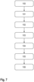
- FIG 7 a flow chart is shown which illustrates a method for treating first items of clothing 21 or second items of clothing 21 according to a preferred embodiment of the present invention.
- the method starts with arranging 100 the first item of clothing 31 and the second item of clothing 32 in the device 1 with integrated laundry treatment functionality.
- the first item of clothing is preferably pulled onto a first carrier 31 or the second item of clothing 22 onto the second carrier 32 in advance.
- the movement 101 of the first carrier 31 and/or the second carrier 32 to release 102 the first item of clothing 21 or one side S of the first garment 22.
- the treatment 103 of the first garment 12 and/or one side S of the first garment 21 is followed by the treatment 103 of the first garment 12 and/or one side S of the first garment 21.
- a further movement 104 of the first wearer 31 and/or the second Wearer 32 causes the second item of clothing 22 or another side of the first item of clothing 21 to be exposed.
- a further treatment 105 is carried out on the second item of clothing 22 or the other side S of the second garment 22 made. After the further treatment of all items of clothing 21, 22 has been completed, they are ready for removal 106 from the device 1 with integrated laundry treatment functionality.
Landscapes
- Engineering & Computer Science (AREA)
- Textile Engineering (AREA)
- Accessory Of Washing/Drying Machine, Commercial Washing/Drying Machine, Other Washing/Drying Machine (AREA)
- Treatment Of Fiber Materials (AREA)
Applications Claiming Priority (1)
| Application Number | Priority Date | Filing Date | Title |
|---|---|---|---|
| DE102018221470.0A DE102018221470A1 (de) | 2018-12-12 | 2018-12-12 | Vorrichtung mit integrierter Wäschebehandlungsfunktionalität und Verfahren zum Nutzen einer solchen Vorrichtung |
Publications (2)
| Publication Number | Publication Date |
|---|---|
| EP3666962A1 EP3666962A1 (de) | 2020-06-17 |
| EP3666962B1 true EP3666962B1 (de) | 2023-03-08 |
Family
ID=68766563
Family Applications (1)
| Application Number | Title | Priority Date | Filing Date |
|---|---|---|---|
| EP19213093.8A Active EP3666962B1 (de) | 2018-12-12 | 2019-12-03 | Vorrichtung mit integrierter wäschebehandlungsfunktionalität und verfahren zum nutzen einer solchen vorrichtung |
Country Status (4)
| Country | Link |
|---|---|
| EP (1) | EP3666962B1 (pl) |
| CN (1) | CN111297064B (pl) |
| DE (1) | DE102018221470A1 (pl) |
| PL (1) | PL3666962T3 (pl) |
Families Citing this family (2)
| Publication number | Priority date | Publication date | Assignee | Title |
|---|---|---|---|---|
| DE102020211153A1 (de) * | 2020-09-04 | 2022-03-10 | BSH Hausgeräte GmbH | Wäschebehandlungsgerät |
| CN113142816B (zh) * | 2021-04-27 | 2022-10-04 | 嘉兴市裕胜家居有限公司 | 一种基于物联网技术的智能衣柜 |
Family Cites Families (18)
| Publication number | Priority date | Publication date | Assignee | Title |
|---|---|---|---|---|
| CH688053A5 (de) * | 1994-07-19 | 1997-04-30 | Walter Steiner | Vorrichtung zum Trocknen von Waeschestuecken. |
| JP2002000997A (ja) * | 2000-06-26 | 2002-01-08 | Matsushita Electric Ind Co Ltd | 衣類乾燥機 |
| JP2002136798A (ja) * | 2000-10-30 | 2002-05-14 | Suzuki Sangyo Kk | 乾燥・殺菌・消臭装置 |
| DE102006050015B4 (de) * | 2006-08-14 | 2021-12-02 | Herbert Kannegiesser Gmbh | Verfahren zum Glätten von Bekleidungsstücken und Tunnelfinisher |
| DE102007033912A1 (de) * | 2006-08-14 | 2008-02-21 | Herbert Kannegiesser Gmbh | Verfahren zum Glätten von Bekleidungsstücken und Tunnelfinisher |
| KR101113884B1 (ko) * | 2009-03-03 | 2012-02-29 | 엘지전자 주식회사 | 의류처리장치 |
| KR20120080947A (ko) * | 2011-01-10 | 2012-07-18 | 엘지전자 주식회사 | 의류처리장치의 운전방법 |
| CN102641046B (zh) * | 2012-03-31 | 2014-03-05 | 北京印刷学院 | 循环自动储物柜 |
| CN203676488U (zh) * | 2013-11-22 | 2014-07-02 | 比亚迪股份有限公司 | 一种移门衣柜 |
| KR102099179B1 (ko) | 2013-12-05 | 2020-04-09 | 엘지전자 주식회사 | 의류처리장치 |
| JP2015196007A (ja) * | 2014-04-02 | 2015-11-09 | 正剛 南部 | 洗濯ハンガーの固定具 |
| KR101690619B1 (ko) * | 2014-09-04 | 2016-12-28 | 엘지전자 주식회사 | 의류처리장치 및 의류처리장치의 제어방법 |
| KR102254890B1 (ko) * | 2014-09-30 | 2021-05-24 | 엘지전자 주식회사 | 의류처리장치 |
| US9809924B2 (en) | 2014-12-19 | 2017-11-07 | Lg Electronics Inc. | Clothes treatment apparatus |
| KR102591759B1 (ko) * | 2015-05-08 | 2023-10-23 | 삼성전자주식회사 | 건조기 및 그 제어 방법 |
| KR101595725B1 (ko) * | 2015-07-30 | 2016-02-19 | 김종란 | 다기능 의류 세탁 관리장치 |
| DE202016008146U1 (de) * | 2015-09-18 | 2017-04-05 | Cornelius Bobbert | Trocken- oder Wäscheständer |
| DE102017104112A1 (de) * | 2017-02-28 | 2018-08-30 | Cornelius Bobbert | Trocken- oder Wäscheständer |
-
2018
- 2018-12-12 DE DE102018221470.0A patent/DE102018221470A1/de not_active Withdrawn
-
2019
- 2019-12-03 PL PL19213093.8T patent/PL3666962T3/pl unknown
- 2019-12-03 EP EP19213093.8A patent/EP3666962B1/de active Active
- 2019-12-10 CN CN201911257343.5A patent/CN111297064B/zh active Active
Also Published As
| Publication number | Publication date |
|---|---|
| CN111297064A (zh) | 2020-06-19 |
| EP3666962A1 (de) | 2020-06-17 |
| DE102018221470A1 (de) | 2020-06-18 |
| PL3666962T3 (pl) | 2023-06-12 |
| CN111297064B (zh) | 2023-01-24 |
Similar Documents
| Publication | Publication Date | Title |
|---|---|---|
| EP3666962B1 (de) | Vorrichtung mit integrierter wäschebehandlungsfunktionalität und verfahren zum nutzen einer solchen vorrichtung | |
| DE202012104276U1 (de) | Stoffbehandlungsvorrichtung | |
| DE202012009608U1 (de) | Stylersystem für mehrere Kleidungsstücke | |
| DE102009018770B4 (de) | Maschine zum Behandeln von Textil- und Lederwaren | |
| DE10030531A1 (de) | Verfahren und Vorrichtung zur bügelfreien Trocknung von feuchtem Gut, insbesondere von feuchter Wäsche bzw. Kleidung | |
| DE2100116A1 (de) | Verfahren und Vorrichtung zum Aufformen, Aufdunsten, Ausrüsten od dergl von Kleidungsstücken | |
| DE4235560C2 (de) | Verfahren zum Entgiften, Lüften, Trocknen und Sterilisieren von Geweben und dergleichen sowie Gerät zur Durchführung des Verfahrens | |
| EP2050862A1 (de) | Flusenfiltervorrichtung und Hausgerät mit einer derartigen Flusenfiltervorrichtung | |
| DE10316503B3 (de) | Backofen und Verfahren zum Betrieb eines Backofens | |
| DE112010005497B4 (de) | Steuerverfahren für eine Wäschebehandlungsvorrichtung | |
| DE102011075501A1 (de) | Verfahren zum schonenden Entkeimen von Wäsche und Waschtrockeneinheit | |
| DE112008002090T5 (de) | Kleidungs-Behandlungsvorrichtung und Verfahren zur Steuerung derselben | |
| EP3138951A1 (de) | Anordnung und verfahren zum einleiten von prozessluft in eine wäschetrommel eines wäschetrockners | |
| DE2915443C2 (de) | Verfahren und Vorrichtung zum Glätten von Kleidungsstücken | |
| DE112010004819B4 (de) | Steuerverfahren für eine Wäschebehandlungsvorrichtung | |
| EP1889969A2 (de) | Verfahren zum Glätten von Bekleidungsstücken und Tunnelfinisher | |
| EP0632965B2 (de) | Verfahren zum mehrstufigen Behandeln von stückigen Produkten mittels Prozessmedien und Vorrichtung zur Durchführung des Verfahrens | |
| DE102008015130A1 (de) | Trocknungsvorrichtung mit mindestens zwei Trommeln | |
| DE2122577C3 (de) | Verfahren und Vorrichtung zum Trocknen und gleichzeitigen Glätten gewaschener Kleidungsstucke | |
| EP3666961B1 (de) | Vorrichtung mit integrierter wäschebehandlungsfunktionalität, träger für eine solche vorrichtung und verfahren zum nutzen einer solchen vorrichtung | |
| DE102007033912A1 (de) | Verfahren zum Glätten von Bekleidungsstücken und Tunnelfinisher | |
| WO2006072515A1 (de) | Steuereinheit für den zulauf von wasserführenden haushaltgeräten | |
| DE102020215475A1 (de) | Behandlungsmodul für einen Wäschebehandlungsschrank, Wäschebehandlungsschrank und Verfahren zum Betreiben eines Wäschebehandlungsschranks | |
| EP1808522B1 (de) | Vorrichtung zum Glätten von Kleidung | |
| DE102020215476A1 (de) | Wäschebehandlungsschrank und Verfahren zum Betreiben eines Wäschebehandlungsschranks |
Legal Events
| Date | Code | Title | Description |
|---|---|---|---|
| PUAI | Public reference made under article 153(3) epc to a published international application that has entered the european phase |
Free format text: ORIGINAL CODE: 0009012 |
|
| STAA | Information on the status of an ep patent application or granted ep patent |
Free format text: STATUS: THE APPLICATION HAS BEEN PUBLISHED |
|
| AK | Designated contracting states |
Kind code of ref document: A1 Designated state(s): AL AT BE BG CH CY CZ DE DK EE ES FI FR GB GR HR HU IE IS IT LI LT LU LV MC MK MT NL NO PL PT RO RS SE SI SK SM TR |
|
| AX | Request for extension of the european patent |
Extension state: BA ME |
|
| STAA | Information on the status of an ep patent application or granted ep patent |
Free format text: STATUS: REQUEST FOR EXAMINATION WAS MADE |
|
| 17P | Request for examination filed |
Effective date: 20201217 |
|
| RBV | Designated contracting states (corrected) |
Designated state(s): AL AT BE BG CH CY CZ DE DK EE ES FI FR GB GR HR HU IE IS IT LI LT LU LV MC MK MT NL NO PL PT RO RS SE SI SK SM TR |
|
| GRAP | Despatch of communication of intention to grant a patent |
Free format text: ORIGINAL CODE: EPIDOSNIGR1 |
|
| STAA | Information on the status of an ep patent application or granted ep patent |
Free format text: STATUS: GRANT OF PATENT IS INTENDED |
|
| INTG | Intention to grant announced |
Effective date: 20221028 |
|
| GRAS | Grant fee paid |
Free format text: ORIGINAL CODE: EPIDOSNIGR3 |
|
| GRAA | (expected) grant |
Free format text: ORIGINAL CODE: 0009210 |
|
| STAA | Information on the status of an ep patent application or granted ep patent |
Free format text: STATUS: THE PATENT HAS BEEN GRANTED |
|
| AK | Designated contracting states |
Kind code of ref document: B1 Designated state(s): AL AT BE BG CH CY CZ DE DK EE ES FI FR GB GR HR HU IE IS IT LI LT LU LV MC MK MT NL NO PL PT RO RS SE SI SK SM TR |
|
| REG | Reference to a national code |
Ref country code: CH Ref legal event code: EP Ref country code: AT Ref legal event code: REF Ref document number: 1552647 Country of ref document: AT Kind code of ref document: T Effective date: 20230315 |
|
| REG | Reference to a national code |
Ref country code: IE Ref legal event code: FG4D Free format text: LANGUAGE OF EP DOCUMENT: GERMAN |
|
| REG | Reference to a national code |
Ref country code: DE Ref legal event code: R096 Ref document number: 502019007144 Country of ref document: DE |
|
| REG | Reference to a national code |
Ref country code: LT Ref legal event code: MG9D |
|
| REG | Reference to a national code |
Ref country code: NL Ref legal event code: MP Effective date: 20230308 |
|
| PG25 | Lapsed in a contracting state [announced via postgrant information from national office to epo] |
Ref country code: RS Free format text: LAPSE BECAUSE OF FAILURE TO SUBMIT A TRANSLATION OF THE DESCRIPTION OR TO PAY THE FEE WITHIN THE PRESCRIBED TIME-LIMIT Effective date: 20230308 Ref country code: NO Free format text: LAPSE BECAUSE OF FAILURE TO SUBMIT A TRANSLATION OF THE DESCRIPTION OR TO PAY THE FEE WITHIN THE PRESCRIBED TIME-LIMIT Effective date: 20230608 Ref country code: LV Free format text: LAPSE BECAUSE OF FAILURE TO SUBMIT A TRANSLATION OF THE DESCRIPTION OR TO PAY THE FEE WITHIN THE PRESCRIBED TIME-LIMIT Effective date: 20230308 Ref country code: LT Free format text: LAPSE BECAUSE OF FAILURE TO SUBMIT A TRANSLATION OF THE DESCRIPTION OR TO PAY THE FEE WITHIN THE PRESCRIBED TIME-LIMIT Effective date: 20230308 Ref country code: HR Free format text: LAPSE BECAUSE OF FAILURE TO SUBMIT A TRANSLATION OF THE DESCRIPTION OR TO PAY THE FEE WITHIN THE PRESCRIBED TIME-LIMIT Effective date: 20230308 Ref country code: ES Free format text: LAPSE BECAUSE OF FAILURE TO SUBMIT A TRANSLATION OF THE DESCRIPTION OR TO PAY THE FEE WITHIN THE PRESCRIBED TIME-LIMIT Effective date: 20230308 |
|
| PG25 | Lapsed in a contracting state [announced via postgrant information from national office to epo] |
Ref country code: SE Free format text: LAPSE BECAUSE OF FAILURE TO SUBMIT A TRANSLATION OF THE DESCRIPTION OR TO PAY THE FEE WITHIN THE PRESCRIBED TIME-LIMIT Effective date: 20230308 Ref country code: NL Free format text: LAPSE BECAUSE OF FAILURE TO SUBMIT A TRANSLATION OF THE DESCRIPTION OR TO PAY THE FEE WITHIN THE PRESCRIBED TIME-LIMIT Effective date: 20230308 Ref country code: GR Free format text: LAPSE BECAUSE OF FAILURE TO SUBMIT A TRANSLATION OF THE DESCRIPTION OR TO PAY THE FEE WITHIN THE PRESCRIBED TIME-LIMIT Effective date: 20230609 Ref country code: FI Free format text: LAPSE BECAUSE OF FAILURE TO SUBMIT A TRANSLATION OF THE DESCRIPTION OR TO PAY THE FEE WITHIN THE PRESCRIBED TIME-LIMIT Effective date: 20230308 |
|
| PG25 | Lapsed in a contracting state [announced via postgrant information from national office to epo] |
Ref country code: SM Free format text: LAPSE BECAUSE OF FAILURE TO SUBMIT A TRANSLATION OF THE DESCRIPTION OR TO PAY THE FEE WITHIN THE PRESCRIBED TIME-LIMIT Effective date: 20230308 Ref country code: RO Free format text: LAPSE BECAUSE OF FAILURE TO SUBMIT A TRANSLATION OF THE DESCRIPTION OR TO PAY THE FEE WITHIN THE PRESCRIBED TIME-LIMIT Effective date: 20230308 Ref country code: PT Free format text: LAPSE BECAUSE OF FAILURE TO SUBMIT A TRANSLATION OF THE DESCRIPTION OR TO PAY THE FEE WITHIN THE PRESCRIBED TIME-LIMIT Effective date: 20230710 Ref country code: EE Free format text: LAPSE BECAUSE OF FAILURE TO SUBMIT A TRANSLATION OF THE DESCRIPTION OR TO PAY THE FEE WITHIN THE PRESCRIBED TIME-LIMIT Effective date: 20230308 Ref country code: CZ Free format text: LAPSE BECAUSE OF FAILURE TO SUBMIT A TRANSLATION OF THE DESCRIPTION OR TO PAY THE FEE WITHIN THE PRESCRIBED TIME-LIMIT Effective date: 20230308 |
|
| PG25 | Lapsed in a contracting state [announced via postgrant information from national office to epo] |
Ref country code: SK Free format text: LAPSE BECAUSE OF FAILURE TO SUBMIT A TRANSLATION OF THE DESCRIPTION OR TO PAY THE FEE WITHIN THE PRESCRIBED TIME-LIMIT Effective date: 20230308 Ref country code: IS Free format text: LAPSE BECAUSE OF FAILURE TO SUBMIT A TRANSLATION OF THE DESCRIPTION OR TO PAY THE FEE WITHIN THE PRESCRIBED TIME-LIMIT Effective date: 20230708 |
|
| REG | Reference to a national code |
Ref country code: DE Ref legal event code: R097 Ref document number: 502019007144 Country of ref document: DE |
|
| PLBE | No opposition filed within time limit |
Free format text: ORIGINAL CODE: 0009261 |
|
| STAA | Information on the status of an ep patent application or granted ep patent |
Free format text: STATUS: NO OPPOSITION FILED WITHIN TIME LIMIT |
|
| PG25 | Lapsed in a contracting state [announced via postgrant information from national office to epo] |
Ref country code: SI Free format text: LAPSE BECAUSE OF FAILURE TO SUBMIT A TRANSLATION OF THE DESCRIPTION OR TO PAY THE FEE WITHIN THE PRESCRIBED TIME-LIMIT Effective date: 20230308 Ref country code: DK Free format text: LAPSE BECAUSE OF FAILURE TO SUBMIT A TRANSLATION OF THE DESCRIPTION OR TO PAY THE FEE WITHIN THE PRESCRIBED TIME-LIMIT Effective date: 20230308 |
|
| 26N | No opposition filed |
Effective date: 20231211 |
|
| PG25 | Lapsed in a contracting state [announced via postgrant information from national office to epo] |
Ref country code: IT Free format text: LAPSE BECAUSE OF FAILURE TO SUBMIT A TRANSLATION OF THE DESCRIPTION OR TO PAY THE FEE WITHIN THE PRESCRIBED TIME-LIMIT Effective date: 20230308 |
|
| REG | Reference to a national code |
Ref country code: CH Ref legal event code: PL |
|
| PG25 | Lapsed in a contracting state [announced via postgrant information from national office to epo] |
Ref country code: LU Free format text: LAPSE BECAUSE OF NON-PAYMENT OF DUE FEES Effective date: 20231203 |
|
| PG25 | Lapsed in a contracting state [announced via postgrant information from national office to epo] |
Ref country code: MC Free format text: LAPSE BECAUSE OF FAILURE TO SUBMIT A TRANSLATION OF THE DESCRIPTION OR TO PAY THE FEE WITHIN THE PRESCRIBED TIME-LIMIT Effective date: 20230308 |
|
| GBPC | Gb: european patent ceased through non-payment of renewal fee |
Effective date: 20231203 |
|
| REG | Reference to a national code |
Ref country code: BE Ref legal event code: MM Effective date: 20231231 |
|
| PG25 | Lapsed in a contracting state [announced via postgrant information from national office to epo] |
Ref country code: MC Free format text: LAPSE BECAUSE OF FAILURE TO SUBMIT A TRANSLATION OF THE DESCRIPTION OR TO PAY THE FEE WITHIN THE PRESCRIBED TIME-LIMIT Effective date: 20230308 Ref country code: LU Free format text: LAPSE BECAUSE OF NON-PAYMENT OF DUE FEES Effective date: 20231203 |
|
| REG | Reference to a national code |
Ref country code: IE Ref legal event code: MM4A |
|
| PG25 | Lapsed in a contracting state [announced via postgrant information from national office to epo] |
Ref country code: IE Free format text: LAPSE BECAUSE OF NON-PAYMENT OF DUE FEES Effective date: 20231203 |
|
| PG25 | Lapsed in a contracting state [announced via postgrant information from national office to epo] |
Ref country code: GB Free format text: LAPSE BECAUSE OF NON-PAYMENT OF DUE FEES Effective date: 20231203 |
|
| PG25 | Lapsed in a contracting state [announced via postgrant information from national office to epo] |
Ref country code: BE Free format text: LAPSE BECAUSE OF NON-PAYMENT OF DUE FEES Effective date: 20231231 |
|
| PG25 | Lapsed in a contracting state [announced via postgrant information from national office to epo] |
Ref country code: FR Free format text: LAPSE BECAUSE OF NON-PAYMENT OF DUE FEES Effective date: 20231231 |
|
| PG25 | Lapsed in a contracting state [announced via postgrant information from national office to epo] |
Ref country code: CH Free format text: LAPSE BECAUSE OF NON-PAYMENT OF DUE FEES Effective date: 20231231 |
|
| PG25 | Lapsed in a contracting state [announced via postgrant information from national office to epo] |
Ref country code: IE Free format text: LAPSE BECAUSE OF NON-PAYMENT OF DUE FEES Effective date: 20231203 Ref country code: GB Free format text: LAPSE BECAUSE OF NON-PAYMENT OF DUE FEES Effective date: 20231203 Ref country code: FR Free format text: LAPSE BECAUSE OF NON-PAYMENT OF DUE FEES Effective date: 20231231 Ref country code: CH Free format text: LAPSE BECAUSE OF NON-PAYMENT OF DUE FEES Effective date: 20231231 Ref country code: BE Free format text: LAPSE BECAUSE OF NON-PAYMENT OF DUE FEES Effective date: 20231231 |
|
| PG25 | Lapsed in a contracting state [announced via postgrant information from national office to epo] |
Ref country code: BG Free format text: LAPSE BECAUSE OF FAILURE TO SUBMIT A TRANSLATION OF THE DESCRIPTION OR TO PAY THE FEE WITHIN THE PRESCRIBED TIME-LIMIT Effective date: 20230308 |
|
| PG25 | Lapsed in a contracting state [announced via postgrant information from national office to epo] |
Ref country code: BG Free format text: LAPSE BECAUSE OF FAILURE TO SUBMIT A TRANSLATION OF THE DESCRIPTION OR TO PAY THE FEE WITHIN THE PRESCRIBED TIME-LIMIT Effective date: 20230308 |
|
| PG25 | Lapsed in a contracting state [announced via postgrant information from national office to epo] |
Ref country code: CY Free format text: LAPSE BECAUSE OF FAILURE TO SUBMIT A TRANSLATION OF THE DESCRIPTION OR TO PAY THE FEE WITHIN THE PRESCRIBED TIME-LIMIT; INVALID AB INITIO Effective date: 20191203 |
|
| PG25 | Lapsed in a contracting state [announced via postgrant information from national office to epo] |
Ref country code: HU Free format text: LAPSE BECAUSE OF FAILURE TO SUBMIT A TRANSLATION OF THE DESCRIPTION OR TO PAY THE FEE WITHIN THE PRESCRIBED TIME-LIMIT; INVALID AB INITIO Effective date: 20191203 |
|
| PGFP | Annual fee paid to national office [announced via postgrant information from national office to epo] |
Ref country code: TR Payment date: 20251128 Year of fee payment: 7 |
|
| PGFP | Annual fee paid to national office [announced via postgrant information from national office to epo] |
Ref country code: PL Payment date: 20251125 Year of fee payment: 7 |
|
| REG | Reference to a national code |
Ref country code: AT Ref legal event code: MM01 Ref document number: 1552647 Country of ref document: AT Kind code of ref document: T Effective date: 20241203 |
|
| PGFP | Annual fee paid to national office [announced via postgrant information from national office to epo] |
Ref country code: DE Payment date: 20251231 Year of fee payment: 7 |
|
| PG25 | Lapsed in a contracting state [announced via postgrant information from national office to epo] |
Ref country code: AT Free format text: LAPSE BECAUSE OF NON-PAYMENT OF DUE FEES Effective date: 20241203 |
|
| PGFP | Annual fee paid to national office [announced via postgrant information from national office to epo] |
Ref country code: AT Payment date: 20260410 Year of fee payment: 5 |