EP3667084A1 - Conenction structure for motor of air compressor - Google Patents
Conenction structure for motor of air compressor Download PDFInfo
- Publication number
- EP3667084A1 EP3667084A1 EP19216553.8A EP19216553A EP3667084A1 EP 3667084 A1 EP3667084 A1 EP 3667084A1 EP 19216553 A EP19216553 A EP 19216553A EP 3667084 A1 EP3667084 A1 EP 3667084A1
- Authority
- EP
- European Patent Office
- Prior art keywords
- base
- motor
- symmetrical
- magnetic coil
- segment
- Prior art date
- Legal status (The legal status is an assumption and is not a legal conclusion. Google has not performed a legal analysis and makes no representation as to the accuracy of the status listed.)
- Granted
Links
Images


Classifications
-
- F—MECHANICAL ENGINEERING; LIGHTING; HEATING; WEAPONS; BLASTING
- F04—POSITIVE - DISPLACEMENT MACHINES FOR LIQUIDS; PUMPS FOR LIQUIDS OR ELASTIC FLUIDS
- F04B—POSITIVE-DISPLACEMENT MACHINES FOR LIQUIDS; PUMPS
- F04B35/00—Piston pumps specially adapted for elastic fluids and characterised by the driving means to their working members, or by combination with, or adaptation to, specific driving engines or motors, not otherwise provided for
- F04B35/04—Piston pumps specially adapted for elastic fluids and characterised by the driving means to their working members, or by combination with, or adaptation to, specific driving engines or motors, not otherwise provided for the means being electric
-
- F—MECHANICAL ENGINEERING; LIGHTING; HEATING; WEAPONS; BLASTING
- F04—POSITIVE - DISPLACEMENT MACHINES FOR LIQUIDS; PUMPS FOR LIQUIDS OR ELASTIC FLUIDS
- F04B—POSITIVE-DISPLACEMENT MACHINES FOR LIQUIDS; PUMPS
- F04B39/00—Component parts, details, or accessories, of pumps or pumping systems specially adapted for elastic fluids, not otherwise provided for in, or of interest apart from, groups F04B25/00 - F04B37/00
- F04B39/12—Casings; Cylinders; Cylinder heads; Fluid connections
- F04B39/121—Casings
-
- F—MECHANICAL ENGINEERING; LIGHTING; HEATING; WEAPONS; BLASTING
- F04—POSITIVE - DISPLACEMENT MACHINES FOR LIQUIDS; PUMPS FOR LIQUIDS OR ELASTIC FLUIDS
- F04B—POSITIVE-DISPLACEMENT MACHINES FOR LIQUIDS; PUMPS
- F04B39/00—Component parts, details, or accessories, of pumps or pumping systems specially adapted for elastic fluids, not otherwise provided for in, or of interest apart from, groups F04B25/00 - F04B37/00
- F04B39/14—Provisions for readily assembling or disassembling
-
- F—MECHANICAL ENGINEERING; LIGHTING; HEATING; WEAPONS; BLASTING
- F04—POSITIVE - DISPLACEMENT MACHINES FOR LIQUIDS; PUMPS FOR LIQUIDS OR ELASTIC FLUIDS
- F04B—POSITIVE-DISPLACEMENT MACHINES FOR LIQUIDS; PUMPS
- F04B41/00—Pumping installations or systems specially adapted for elastic fluids
-
- F—MECHANICAL ENGINEERING; LIGHTING; HEATING; WEAPONS; BLASTING
- F04—POSITIVE - DISPLACEMENT MACHINES FOR LIQUIDS; PUMPS FOR LIQUIDS OR ELASTIC FLUIDS
- F04B—POSITIVE-DISPLACEMENT MACHINES FOR LIQUIDS; PUMPS
- F04B53/00—Component parts, details or accessories not provided for in, or of interest apart from, groups F04B1/00 - F04B23/00 or F04B39/00 - F04B47/00
- F04B53/16—Casings; Cylinders; Cylinder liners or heads; Fluid connections
-
- F—MECHANICAL ENGINEERING; LIGHTING; HEATING; WEAPONS; BLASTING
- F04—POSITIVE - DISPLACEMENT MACHINES FOR LIQUIDS; PUMPS FOR LIQUIDS OR ELASTIC FLUIDS
- F04B—POSITIVE-DISPLACEMENT MACHINES FOR LIQUIDS; PUMPS
- F04B53/00—Component parts, details or accessories not provided for in, or of interest apart from, groups F04B1/00 - F04B23/00 or F04B39/00 - F04B47/00
- F04B53/22—Arrangements for enabling ready assembly or disassembly
Definitions
- the present invention relates to a connection structure for a motor of an air compressor which is capable of fixing the motor on the base without using any screw(s).
- a conventional air compressor 1 is mounted on a vehicle and contains a base 11, a cylinder 12 connected on the base 11, a motor 13 fixed on the base 11, and a piston 14 driven by the motor 13 to move in the cylinder 12 reciprocately so as to draw, compress, and discharge air.
- the motor 13 is fixed on the base 11 by using multiple screws 15. However, the multiple screws 15 are removed easily after a period of using time.
- the present invention has arisen to mitigate and/or obviate the afore-described disadvantages.
- the primary aspect of the present invention is to provide a connection structure for a motor of an air compressor which is capable of fixing the motor on the base without using any screw(s).
- the multiple through orifices of the front face are engaged on the multiple posts of the base individually, and the bearing housing of the front face of the motor is received in the first positioning orifice of the base, wherein an outer wall of the motor is retained by the two symmetrical arcuate retainers of the base.
- the first segment of the magnetic coil of the motor abuts against two top faces of the two symmetrical arcuate retainers, and the two hooks of the two symmetrical elongated plates of the base are engaged with the second segment of the magnetic coil so that the motor is fixed on the base securely.
- the air compressor 2 comprises: a base 3, a cylinder 4 connected on the base 3, the motor 7 fixed on the base 3, and a piston 5 driven by the motor 7 to move in the cylinder 4 reciprocately.
- the base 3 includes multiple positioning orifices which are a first positioning orifice 31 and a second positioning orifice 32, wherein a small-diameter gear 61 is inserted through the first positioning orifice 31 to fit on a central shaft of the motor 7, and a bearing housing 71 of the motor 7 is accommodated in the first positioning orifice 31, a diameter A of a top of the small-diameter gear 61 is less than an outer diameter B of the bearing housing 71, and the second positioning orifice 32 accommodates a bearing 37.
- the motor 7 includes a magnetic coil 72 made of metal and configured to guide magnetism so as to enhance operating efficiency of the motor 7.
- the cylinder 4 is one-piece or is movably connected on the base 3, and the cylinder 4 includes an air storage seat 41, an air pipe connected with the air storage seat 41 and configured to delivery air, and a pressure gauge 42 coupled on the air storage seat 41.
- the diameter A of the top of the small-diameter gear 61 is more than the outer diameter B of the bearing housing 71, as shown in FIG. 5 .
- a transmission mechanism 6 includes a large-diameter gear 62 having a counterweight block and meshing with the small-diameter gear 61, wherein the large-diameter gear 62 is connected with the bearing 37 via a connection rod (not shown), and the transmission mechanism 6 actuates the piston 5 to move in the cylinder 4 reciprocately so as to compress the air.
- the magnetic coil 72 of the motor 7 includes a first segment 721 and a second segment 722, and the motor 7 includes multiple through orifices 74, 75 defined around a front face 70 thereof, wherein the small-diameter gear 61 is fitted on the front face 70 of the motor 7.
- the base 3 includes two symmetrical elongated plates 33 extending from a rear end of the base 3, and the two symmetrical elongated plates 33 have two hooks 331 extending therefrom respectively.
- the base 3 further includes two symmetrical arcuate retainers 34 extending from two inner walls of the two symmetrical elongated plates 33 individually, multiple posts 35, 36 (as shown in FIG.
- the multiple through orifices 74, 75 of the front face 70 are engaged on the multiple posts 35, 36 of the base 3 individually, and the bearing housing 71 of the front face 70 of the motor 7 is received in the first positioning orifice 31 of the base 3, wherein an outer wall of the motor 7 is retained by the two symmetrical arcuate retainers 34 of the base 3.
- two symmetrical fixing orifices 723 are defined between the first segment 721 and the second segment 722 of the magnetic coil 72 so that the two hooks 331 of the two symmetrical elongated plates 33 of the base 3 are engaged with the two symmetrical fixing orifices 723 of the magnetic coil 72 respectively, and the motor 7 is fixed on the base 3 securely.
- the multiple through orifices 74, 75 of the motor 7 are engaged on the multiple posts 35, 36 of the base 3 individually, and the bearing housing 71 of the front face 70 of the motor 7 is received in the first positioning orifice 31 of the base 3, wherein the outer wall of the motor 7 is retained by the two symmetrical arcuate retainers 34 of the base 3.
- the first segment 721 of the magnetic coil 72 of the motor 7 abuts against two top faces 341 of the two symmetrical arcuate retainers 34, and the two hooks 331 of the two symmetrical elongated plates 33 of the base 3 are engaged with the magnetic coil 72 so that the motor 7 is fixed on the base 3 securely.
Landscapes
- Engineering & Computer Science (AREA)
- Mechanical Engineering (AREA)
- General Engineering & Computer Science (AREA)
- Connection Of Motors, Electrical Generators, Mechanical Devices, And The Like (AREA)
- Compressors, Vaccum Pumps And Other Relevant Systems (AREA)
- Compressor (AREA)
- Reciprocating, Oscillating Or Vibrating Motors (AREA)
Abstract
Description
- The present invention relates to a connection structure for a motor of an air compressor which is capable of fixing the motor on the base without using any screw(s).
- Referring to
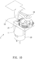
FIGS. 8 and9 , aconventional air compressor 1 is mounted on a vehicle and contains abase 11, acylinder 12 connected on thebase 11, amotor 13 fixed on thebase 11, and apiston 14 driven by themotor 13 to move in thecylinder 12 reciprocately so as to draw, compress, and discharge air. - The
motor 13 is fixed on thebase 11 by usingmultiple screws 15. However, themultiple screws 15 are removed easily after a period of using time. - As illustrated in
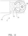
FIGS. 10 and11 , when a length of thecylinder 12 is too long, themotor 13 cannot be fixed on thebase 11. In other words, themotor 13 cannot be fixed on thebase 11 by using themultiple screws 15. - The present invention has arisen to mitigate and/or obviate the afore-described disadvantages.
- The primary aspect of the present invention is to provide a connection structure for a motor of an air compressor which is capable of fixing the motor on the base without using any screw(s).
- In operation, the multiple through orifices of the front face are engaged on the multiple posts of the base individually, and the bearing housing of the front face of the motor is received in the first positioning orifice of the base, wherein an outer wall of the motor is retained by the two symmetrical arcuate retainers of the base. In the meantime, the first segment of the magnetic coil of the motor abuts against two top faces of the two symmetrical arcuate retainers, and the two hooks of the two symmetrical elongated plates of the base are engaged with the second segment of the magnetic coil so that the motor is fixed on the base securely.
-
-
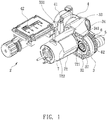
FIG. 1 is a perspective view showing the assembly of an air compressor according to a first embodiment of the present invention. -
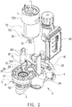
FIG. 2 is a perspective view showing the exploded components of the air compressor according to the first embodiment of the present invention. -
FIG. 3 is a perspective view showing the assembly of a part of the air compressor according to the first embodiment of the present invention. -
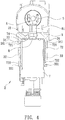
FIG. 4 is a cross sectional view showing the assembly of a part of the air compressor according to the first embodiment of the present invention. -
FIG. 5 is another cross sectional view showing the assembly of a part of the air compressor according to the first embodiment of the present invention. -
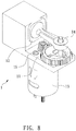
FIG. 6 is a perspective view showing the assembly of an air compressor according to a second embodiment of the present invention. -
FIG. 7 is a perspective view showing the assembly of a part of the air compressor according to the second embodiment of the present invention. -
FIG. 8 is a perspective view showing the assembly of a conventional air compressor. -
FIG. 9 is a side plan view showing the assembly of the conventional air compressor. -
FIG. 10 is another perspective view showing the assembly of the conventional air compressor. -
FIG. 11 is another side plan view showing the assembly of the conventional air compressor. - With reference to
FIGS. 1-3 , a connection structure for amotor 7 of anair compressor 2 according to a first embodiment of the present invention, theair compressor 2 comprises: abase 3, acylinder 4 connected on thebase 3, themotor 7 fixed on thebase 3, and apiston 5 driven by themotor 7 to move in thecylinder 4 reciprocately. - The
base 3 includes multiple positioning orifices which are afirst positioning orifice 31 and asecond positioning orifice 32, wherein a small-diameter gear 61 is inserted through thefirst positioning orifice 31 to fit on a central shaft of themotor 7, and a bearinghousing 71 of themotor 7 is accommodated in thefirst positioning orifice 31, a diameter A of a top of the small-diameter gear 61 is less than an outer diameter B of the bearinghousing 71, and thesecond positioning orifice 32 accommodates abearing 37. Themotor 7 includes amagnetic coil 72 made of metal and configured to guide magnetism so as to enhance operating efficiency of themotor 7. - The
cylinder 4 is one-piece or is movably connected on thebase 3, and thecylinder 4 includes anair storage seat 41, an air pipe connected with theair storage seat 41 and configured to delivery air, and apressure gauge 42 coupled on theair storage seat 41. - The diameter A of the top of the small-
diameter gear 61 is more than the outer diameter B of the bearinghousing 71, as shown inFIG. 5 . - A
transmission mechanism 6 includes a large-diameter gear 62 having a counterweight block and meshing with the small-diameter gear 61, wherein the large-diameter gear 62 is connected with thebearing 37 via a connection rod (not shown), and thetransmission mechanism 6 actuates thepiston 5 to move in thecylinder 4 reciprocately so as to compress the air. - Referring to
FIGS. 2-4 , themagnetic coil 72 of themotor 7 includes afirst segment 721 and asecond segment 722, and themotor 7 includes multiple throughorifices front face 70 thereof, wherein the small-diameter gear 61 is fitted on thefront face 70 of themotor 7. Thebase 3 includes two symmetricalelongated plates 33 extending from a rear end of thebase 3, and the two symmetricalelongated plates 33 have twohooks 331 extending therefrom respectively. Thebase 3 further includes two symmetricalarcuate retainers 34 extending from two inner walls of the two symmetricalelongated plates 33 individually,multiple posts 35, 36 (as shown inFIG. 2 ) extending around thefirst positioning orifice 31 and corresponding to the multiple throughorifices motor 7 on thebase 3, the multiple throughorifices front face 70 are engaged on themultiple posts base 3 individually, and the bearinghousing 71 of thefront face 70 of themotor 7 is received in thefirst positioning orifice 31 of thebase 3, wherein an outer wall of themotor 7 is retained by the two symmetricalarcuate retainers 34 of thebase 3. In the meantime, thefirst segment 721 of themagnetic coil 72 of themotor 7 abuts against twotop faces 341 of the two symmetricalarcuate retainers 34, and the twohooks 331 of the two symmetricalelongated plates 33 of thebase 3 are engaged with thesecond segment 722 of themagnetic coil 72 so that themotor 7 is fixed on thebase 3 securely. - In a second embodiment, as illustrated in
FIGS. 6 and7 , twosymmetrical fixing orifices 723 are defined between thefirst segment 721 and thesecond segment 722 of themagnetic coil 72 so that the twohooks 331 of the two symmetricalelongated plates 33 of thebase 3 are engaged with the twosymmetrical fixing orifices 723 of themagnetic coil 72 respectively, and themotor 7 is fixed on thebase 3 securely. - Thereby, the multiple through
orifices motor 7 are engaged on themultiple posts base 3 individually, and the bearinghousing 71 of thefront face 70 of themotor 7 is received in thefirst positioning orifice 31 of thebase 3, wherein the outer wall of themotor 7 is retained by the two symmetricalarcuate retainers 34 of thebase 3. In the meantime, thefirst segment 721 of themagnetic coil 72 of themotor 7 abuts against twotop faces 341 of the two symmetricalarcuate retainers 34, and the twohooks 331 of the two symmetricalelongated plates 33 of thebase 3 are engaged with themagnetic coil 72 so that themotor 7 is fixed on thebase 3 securely.
Claims (7)
- A connection structure for a motor (7) of an air compressor (2) comprising:a base (3) including multiple positioning orifices which are a first positioning orifice (31) and a second positioning orifice (32);a cylinder (4) connected on the base (3) and including an air storage seat (41);a motor (7) fixed on the base (3), a small-diameter gear (61) being inserted through the first positioning orifice (31) of the base (3) to fit on a central shaft of the motor (7), a bearing housing (71) of the motor (7) being accommodated in the first positioning orifice (31), and the motor (7) including a magnetic coil (72) made of metal; anda transmission mechanism (6) actuating a piston (5) to move in the cylinder (4) reciprocately so as to compress air;characterized in that:the magnetic coil (72) of the motor (7) includes a first segment (721) and a second segment (722), the base (3) includes two symmetrical elongated plates (33) extending from a rear end of the base (3), and the two symmetrical elongated plates (33) have two hooks (331) extending therefrom respectively, the base (3) further includes two symmetrical arcuate retainers (34) extending from two inner walls of the two symmetrical elongated plates (33) individually;the first segment (721) of the magnetic coil (72) of the motor (7) abuts against two top faces (341) of the two symmetrical arcuate retainers (34), and the two hooks (331) of the two symmetrical elongated plates (33) of the base (3) are engaged with the magnetic coil (72) so that the motor (7) is fixed on the base (3).
- The connection structure as claimed in claim 1, wherein the two hooks (331) of the two symmetrical elongated plates (33) of the base (3) are engaged with the second segment (722) of the magnetic coil (72) so that the motor (7) is fixed on the base (3) securely.
- The connection structure as claimed in claim 1, wherein a diameter (A) of a top of the small-diameter gear (61) is less than an outer diameter (B) of the bearing housing (71), and the second positioning orifice (32) accommodates a bearing (37).
- The connection structure as claimed in claim 3, wherein the transmission mechanism (6) includes a large-diameter gear (62) having a counterweight block and meshing with the small-diameter gear (61), wherein the large-diameter gear (62) is connected with the bearing (37) via a connection rod.
- The connection structure as claimed in claim 4, wherein the motor (7) includes multiple through orifices (74), (75) defined around a front face (70) thereof, and the base (3) further includes multiple posts (35), (36) extending around the first positioning orifice (31) and corresponding to the multiple through orifices (74), (75) respectively.
- The connection structure as claimed in claim 1, wherein a diameter (A) of a top of the small-diameter gear (61) is more than an outer diameter (B) of the bearing housing (71).
- The connection structure as claimed in claim 1, wherein two symmetrical fixing orifices (723) are defined between the first segment (721) and the second segment (722) of the magnetic coil (72) so that the two hooks (331) of the two symmetrical elongated plates (33) of the base (3) are engaged with the two symmetrical fixing orifices (723) of the magnetic coil (72) respectively, and the motor (7) is fixed on the base (3).
Priority Applications (1)
| Application Number | Priority Date | Filing Date | Title |
|---|---|---|---|
| PL19216553T PL3667084T3 (en) | 2018-12-14 | 2019-12-16 | Conenction structure for motor of air compressor |
Applications Claiming Priority (1)
| Application Number | Priority Date | Filing Date | Title |
|---|---|---|---|
| TW107145367A TWI698581B (en) | 2018-12-14 | 2018-12-14 | Conenction structure for motor of air compressor |
Publications (2)
| Publication Number | Publication Date |
|---|---|
| EP3667084A1 true EP3667084A1 (en) | 2020-06-17 |
| EP3667084B1 EP3667084B1 (en) | 2021-09-22 |
Family
ID=68917620
Family Applications (1)
| Application Number | Title | Priority Date | Filing Date |
|---|---|---|---|
| EP19216553.8A Active EP3667084B1 (en) | 2018-12-14 | 2019-12-16 | Conenction structure for motor of air compressor |
Country Status (10)
| Country | Link |
|---|---|
| US (1) | US11193475B2 (en) |
| EP (1) | EP3667084B1 (en) |
| JP (2) | JP6821773B2 (en) |
| KR (1) | KR102221891B1 (en) |
| CN (2) | CN211623636U (en) |
| DE (1) | DE202019106826U1 (en) |
| DK (1) | DK3667084T3 (en) |
| HU (1) | HUE056921T2 (en) |
| PL (1) | PL3667084T3 (en) |
| TW (1) | TWI698581B (en) |
Cited By (1)
| Publication number | Priority date | Publication date | Assignee | Title |
|---|---|---|---|---|
| EP4092270A1 (en) * | 2021-05-19 | 2022-11-23 | Wen-San Chou | Fixing device of motor of air compressor |
Families Citing this family (8)
| Publication number | Priority date | Publication date | Assignee | Title |
|---|---|---|---|---|
| TWI676509B (en) * | 2017-11-30 | 2019-11-11 | 已久工業股份有限公司 | Method and structure for mounting a bearing to an air compressor |
| JP1625045S (en) * | 2018-07-27 | 2019-02-18 | ||
| JP1624950S (en) * | 2018-07-27 | 2019-02-18 | ||
| TWI691649B (en) * | 2018-12-17 | 2020-04-21 | 周文三 | Positioning structure of motor of air compressor |
| DE102019215027A1 (en) * | 2019-09-30 | 2021-04-01 | Robert Bosch Gmbh | Air compression device |
| TWI784532B (en) * | 2021-05-19 | 2022-11-21 | 周文三 | Air compressor |
| TWI778633B (en) * | 2021-05-24 | 2022-09-21 | 周文三 | Air compressor |
| TWI785623B (en) * | 2021-05-24 | 2022-12-01 | 周文三 | Fixing device of motor of air compressor |
Citations (5)
| Publication number | Priority date | Publication date | Assignee | Title |
|---|---|---|---|---|
| US6193475B1 (en) * | 1999-11-23 | 2001-02-27 | Thomas Industries Inc. | Compressor assembly |
| US20040141855A1 (en) * | 2003-01-15 | 2004-07-22 | Min-Hsieng Wang | Air compressor |
| EP2829770A1 (en) * | 2013-07-22 | 2015-01-28 | Wen-San Jhou | Air compressor having compact structure |
| US20160265541A1 (en) * | 2015-03-11 | 2016-09-15 | Wen-San Chou | Inflator |
| CN108869237A (en) * | 2018-08-10 | 2018-11-23 | 格力休闲体育用品有限公司 | Conducive to the electric inflating pump of heat dissipation |
Family Cites Families (26)
| Publication number | Priority date | Publication date | Assignee | Title |
|---|---|---|---|---|
| DE4445362A1 (en) * | 1994-12-20 | 1996-06-27 | Bosch Gmbh Robert | Piston pump |
| KR200362620Y1 (en) * | 1998-12-17 | 2005-01-21 | 엘지전자 주식회사 | Vibration motor fixing device of mobile phone terminal |
| US6707203B2 (en) * | 2001-11-09 | 2004-03-16 | Pem Management, Inc. | Electric motor with integral attachment means |
| US7462018B2 (en) * | 2002-08-12 | 2008-12-09 | Wen San Chou | Air compressor having stable configuration |
| DE202004013907U1 (en) * | 2004-09-03 | 2006-01-12 | Rietschle Thomas Memmingen Gmbh | Pump e.g. rotary vane pump, has clip flange attached on motor and cooperating with head or its parts to form clip-connection that is indicated by hook and engaging parts, which are equidistantly arranged at circumference of flange |
| US20060083631A1 (en) * | 2004-10-13 | 2006-04-20 | Walbro Engine Management, L.L.C. | Fuel pump assembly |
| US7318422B2 (en) * | 2005-07-27 | 2008-01-15 | Walbro Engine Management, L.L.C. | Fluid pump assembly |
| DE102007024388A1 (en) * | 2007-05-25 | 2008-11-27 | Robert Bosch Gmbh | electrical appliance |
| CN202007755U (en) * | 2011-02-22 | 2011-10-12 | 泓记精密股份有限公司 | Inflating pump easy to assemble |
| CN103906929B (en) * | 2011-08-05 | 2017-12-15 | 瑞思迈发动机及马达技术股份有限公司 | blower |
| TWI477696B (en) * | 2011-09-23 | 2015-03-21 | Wen San Chou | Air compressor transmission mechanism |
| JP6007570B2 (en) * | 2012-04-24 | 2016-10-12 | マックス株式会社 | air compressor |
| DE102012218012A1 (en) * | 2012-10-02 | 2014-04-03 | Alfmeier Präzision AG Baugruppen und Systemlösungen | Housing with two plastic housing parts |
| TWM480599U (en) * | 2013-07-22 | 2014-06-21 | Wen-San Jhou | Assembling positioning structure of motor of air compressor |
| CN104343658A (en) * | 2013-07-26 | 2015-02-11 | 周文三 | Combination positioning structure of motor of air compressor |
| CN203548355U (en) * | 2013-08-29 | 2014-04-16 | 江门市地尔汉宇电器股份有限公司 | Alternating-current permanent magnet drainage pump with improved pump body assembly structure |
| TWI591257B (en) * | 2014-05-15 | 2017-07-11 | 周文三 | Rotating mechanism of an air compressor |
| TWI566505B (en) * | 2015-01-08 | 2017-01-11 | 周文三 | Motor with heat dissipation structure |
| JP6302428B2 (en) * | 2015-05-26 | 2018-03-28 | 株式会社Soken | Cylinder rotary compressor |
| CN104948421B (en) * | 2015-06-30 | 2017-12-19 | 安徽美芝制冷设备有限公司 | Compressor |
| CN107026520A (en) * | 2016-02-02 | 2017-08-08 | 德昌电机(深圳)有限公司 | A kind of medical pump |
| KR101867966B1 (en) | 2016-11-29 | 2018-06-21 | 계양전기 주식회사 | Integral Type Gear Box of Actuator for Electronical Parking Brake |
| JP6876323B2 (en) * | 2017-02-03 | 2021-05-26 | 応研精工株式会社 | Motorized pump |
| CN206972468U (en) * | 2017-07-11 | 2018-02-06 | 苏州欧圣电气股份有限公司 | A kind of air compressor machine |
| CN207420824U (en) * | 2017-11-06 | 2018-05-29 | 深圳市迈格电气有限公司 | Air compressor with easy mounting structure |
| TWI687602B (en) | 2018-08-09 | 2020-03-11 | 已久工業股份有限公司 | Structure of fixing bearing of air compressor |
-
2018
- 2018-12-14 TW TW107145367A patent/TWI698581B/en active
-
2019
- 2019-12-07 DE DE202019106826.4U patent/DE202019106826U1/en active Active
- 2019-12-08 US US16/706,778 patent/US11193475B2/en active Active
- 2019-12-10 KR KR1020190163405A patent/KR102221891B1/en active Active
- 2019-12-11 CN CN201922209996.8U patent/CN211623636U/en not_active Expired - Fee Related
- 2019-12-11 CN CN201911266247.7A patent/CN111322222B/en active Active
- 2019-12-12 JP JP2019224244A patent/JP6821773B2/en active Active
- 2019-12-12 JP JP2019004713U patent/JP3225241U/en active Active
- 2019-12-16 PL PL19216553T patent/PL3667084T3/en unknown
- 2019-12-16 HU HUE19216553A patent/HUE056921T2/en unknown
- 2019-12-16 DK DK19216553.8T patent/DK3667084T3/en active
- 2019-12-16 EP EP19216553.8A patent/EP3667084B1/en active Active
Patent Citations (5)
| Publication number | Priority date | Publication date | Assignee | Title |
|---|---|---|---|---|
| US6193475B1 (en) * | 1999-11-23 | 2001-02-27 | Thomas Industries Inc. | Compressor assembly |
| US20040141855A1 (en) * | 2003-01-15 | 2004-07-22 | Min-Hsieng Wang | Air compressor |
| EP2829770A1 (en) * | 2013-07-22 | 2015-01-28 | Wen-San Jhou | Air compressor having compact structure |
| US20160265541A1 (en) * | 2015-03-11 | 2016-09-15 | Wen-San Chou | Inflator |
| CN108869237A (en) * | 2018-08-10 | 2018-11-23 | 格力休闲体育用品有限公司 | Conducive to the electric inflating pump of heat dissipation |
Cited By (4)
| Publication number | Priority date | Publication date | Assignee | Title |
|---|---|---|---|---|
| EP4092270A1 (en) * | 2021-05-19 | 2022-11-23 | Wen-San Chou | Fixing device of motor of air compressor |
| CN115395703A (en) * | 2021-05-19 | 2022-11-25 | 周文三 | Motor combination positioning device of air compressor |
| US11913440B2 (en) | 2021-05-19 | 2024-02-27 | Wen-San Chou | Fixing device of motor of air compressor |
| CN115395703B (en) * | 2021-05-19 | 2026-02-06 | 周文三 | Motor combined positioning device of air compressor |
Also Published As
| Publication number | Publication date |
|---|---|
| JP2020094585A (en) | 2020-06-18 |
| TWI698581B (en) | 2020-07-11 |
| US11193475B2 (en) | 2021-12-07 |
| KR102221891B1 (en) | 2021-03-05 |
| DE202019106826U1 (en) | 2020-01-21 |
| EP3667084B1 (en) | 2021-09-22 |
| CN111322222A (en) | 2020-06-23 |
| JP3225241U (en) | 2020-02-20 |
| HUE056921T2 (en) | 2022-03-28 |
| JP6821773B2 (en) | 2021-01-27 |
| PL3667084T3 (en) | 2022-04-11 |
| KR20200074871A (en) | 2020-06-25 |
| CN211623636U (en) | 2020-10-02 |
| US20200208620A1 (en) | 2020-07-02 |
| CN111322222B (en) | 2022-04-26 |
| DK3667084T3 (en) | 2021-12-13 |
| TW202022225A (en) | 2020-06-16 |
Similar Documents
| Publication | Publication Date | Title |
|---|---|---|
| EP3667084A1 (en) | Conenction structure for motor of air compressor | |
| EP3670911A1 (en) | Positioning structure of motor of air compressor | |
| US9206799B2 (en) | Mounting arrangement for a resonant spring in a linear motor compressor | |
| EP2818713A3 (en) | Linear compressor | |
| EP3608540A1 (en) | Structure of fixing bearing of air compressor | |
| EP4092269A1 (en) | Air compressor | |
| US11125222B2 (en) | Air compressor | |
| US20210172427A1 (en) | Positioning structure of motor of air compressor | |
| EP4092270A1 (en) | Fixing device of motor of air compressor | |
| EP4095380B1 (en) | Air compressor | |
| US20210190054A1 (en) | Pump | |
| EP4095379B1 (en) | Fixing device of motor of air compressor | |
| EP3628869A1 (en) | Transmission mechanism of air compressor | |
| CN215157232U (en) | Spray gun | |
| CN213039412U (en) | Casing of automobile air conditioner compressor | |
| CN108457841B (en) | Air suction noise reduction mechanism of linear compressor | |
| JPH0521180U (en) | Stroke length adjustment mechanism of metering pump |
Legal Events
| Date | Code | Title | Description |
|---|---|---|---|
| PUAI | Public reference made under article 153(3) epc to a published international application that has entered the european phase |
Free format text: ORIGINAL CODE: 0009012 |
|
| STAA | Information on the status of an ep patent application or granted ep patent |
Free format text: STATUS: REQUEST FOR EXAMINATION WAS MADE |
|
| 17P | Request for examination filed |
Effective date: 20200319 |
|
| AK | Designated contracting states |
Kind code of ref document: A1 Designated state(s): AL AT BE BG CH CY CZ DE DK EE ES FI FR GB GR HR HU IE IS IT LI LT LU LV MC MK MT NL NO PL PT RO RS SE SI SK SM TR |
|
| AX | Request for extension of the european patent |
Extension state: BA ME |
|
| GRAP | Despatch of communication of intention to grant a patent |
Free format text: ORIGINAL CODE: EPIDOSNIGR1 |
|
| STAA | Information on the status of an ep patent application or granted ep patent |
Free format text: STATUS: GRANT OF PATENT IS INTENDED |
|
| INTG | Intention to grant announced |
Effective date: 20210401 |
|
| GRAS | Grant fee paid |
Free format text: ORIGINAL CODE: EPIDOSNIGR3 |
|
| GRAA | (expected) grant |
Free format text: ORIGINAL CODE: 0009210 |
|
| STAA | Information on the status of an ep patent application or granted ep patent |
Free format text: STATUS: THE PATENT HAS BEEN GRANTED |
|
| AK | Designated contracting states |
Kind code of ref document: B1 Designated state(s): AL AT BE BG CH CY CZ DE DK EE ES FI FR GB GR HR HU IE IS IT LI LT LU LV MC MK MT NL NO PL PT RO RS SE SI SK SM TR |
|
| REG | Reference to a national code |
Ref country code: GB Ref legal event code: FG4D |
|
| REG | Reference to a national code |
Ref country code: IE Ref legal event code: FG4D |
|
| REG | Reference to a national code |
Ref country code: DE Ref legal event code: R096 Ref document number: 602019007852 Country of ref document: DE |
|
| REG | Reference to a national code |
Ref country code: CH Ref legal event code: EP Ref country code: AT Ref legal event code: REF Ref document number: 1432528 Country of ref document: AT Kind code of ref document: T Effective date: 20211015 |
|
| REG | Reference to a national code |
Ref country code: DK Ref legal event code: T3 Effective date: 20211209 |
|
| REG | Reference to a national code |
Ref country code: LT Ref legal event code: MG9D |
|
| REG | Reference to a national code |
Ref country code: SE Ref legal event code: TRGR |
|
| REG | Reference to a national code |
Ref country code: NL Ref legal event code: FP |
|
| PG25 | Lapsed in a contracting state [announced via postgrant information from national office to epo] |
Ref country code: FI Free format text: LAPSE BECAUSE OF FAILURE TO SUBMIT A TRANSLATION OF THE DESCRIPTION OR TO PAY THE FEE WITHIN THE PRESCRIBED TIME-LIMIT Effective date: 20210922 Ref country code: HR Free format text: LAPSE BECAUSE OF FAILURE TO SUBMIT A TRANSLATION OF THE DESCRIPTION OR TO PAY THE FEE WITHIN THE PRESCRIBED TIME-LIMIT Effective date: 20210922 Ref country code: NO Free format text: LAPSE BECAUSE OF FAILURE TO SUBMIT A TRANSLATION OF THE DESCRIPTION OR TO PAY THE FEE WITHIN THE PRESCRIBED TIME-LIMIT Effective date: 20211222 Ref country code: LT Free format text: LAPSE BECAUSE OF FAILURE TO SUBMIT A TRANSLATION OF THE DESCRIPTION OR TO PAY THE FEE WITHIN THE PRESCRIBED TIME-LIMIT Effective date: 20210922 Ref country code: BG Free format text: LAPSE BECAUSE OF FAILURE TO SUBMIT A TRANSLATION OF THE DESCRIPTION OR TO PAY THE FEE WITHIN THE PRESCRIBED TIME-LIMIT Effective date: 20211222 Ref country code: RS Free format text: LAPSE BECAUSE OF FAILURE TO SUBMIT A TRANSLATION OF THE DESCRIPTION OR TO PAY THE FEE WITHIN THE PRESCRIBED TIME-LIMIT Effective date: 20210922 |
|
| PGFP | Annual fee paid to national office [announced via postgrant information from national office to epo] |
Ref country code: TR Payment date: 20211210 Year of fee payment: 3 Ref country code: SE Payment date: 20211220 Year of fee payment: 3 Ref country code: FR Payment date: 20211220 Year of fee payment: 3 Ref country code: CZ Payment date: 20211208 Year of fee payment: 3 Ref country code: DK Payment date: 20211220 Year of fee payment: 3 |
|
| PG25 | Lapsed in a contracting state [announced via postgrant information from national office to epo] |
Ref country code: LV Free format text: LAPSE BECAUSE OF FAILURE TO SUBMIT A TRANSLATION OF THE DESCRIPTION OR TO PAY THE FEE WITHIN THE PRESCRIBED TIME-LIMIT Effective date: 20210922 Ref country code: GR Free format text: LAPSE BECAUSE OF FAILURE TO SUBMIT A TRANSLATION OF THE DESCRIPTION OR TO PAY THE FEE WITHIN THE PRESCRIBED TIME-LIMIT Effective date: 20211223 |
|
| PGFP | Annual fee paid to national office [announced via postgrant information from national office to epo] |
Ref country code: BE Payment date: 20211217 Year of fee payment: 3 |
|
| REG | Reference to a national code |
Ref country code: HU Ref legal event code: AG4A Ref document number: E056921 Country of ref document: HU |
|
| PGFP | Annual fee paid to national office [announced via postgrant information from national office to epo] |
Ref country code: HU Payment date: 20211207 Year of fee payment: 3 |
|
| PG25 | Lapsed in a contracting state [announced via postgrant information from national office to epo] |
Ref country code: IS Free format text: LAPSE BECAUSE OF FAILURE TO SUBMIT A TRANSLATION OF THE DESCRIPTION OR TO PAY THE FEE WITHIN THE PRESCRIBED TIME-LIMIT Effective date: 20220122 Ref country code: SK Free format text: LAPSE BECAUSE OF FAILURE TO SUBMIT A TRANSLATION OF THE DESCRIPTION OR TO PAY THE FEE WITHIN THE PRESCRIBED TIME-LIMIT Effective date: 20210922 Ref country code: RO Free format text: LAPSE BECAUSE OF FAILURE TO SUBMIT A TRANSLATION OF THE DESCRIPTION OR TO PAY THE FEE WITHIN THE PRESCRIBED TIME-LIMIT Effective date: 20210922 Ref country code: PT Free format text: LAPSE BECAUSE OF FAILURE TO SUBMIT A TRANSLATION OF THE DESCRIPTION OR TO PAY THE FEE WITHIN THE PRESCRIBED TIME-LIMIT Effective date: 20220124 Ref country code: ES Free format text: LAPSE BECAUSE OF FAILURE TO SUBMIT A TRANSLATION OF THE DESCRIPTION OR TO PAY THE FEE WITHIN THE PRESCRIBED TIME-LIMIT Effective date: 20210922 Ref country code: EE Free format text: LAPSE BECAUSE OF FAILURE TO SUBMIT A TRANSLATION OF THE DESCRIPTION OR TO PAY THE FEE WITHIN THE PRESCRIBED TIME-LIMIT Effective date: 20210922 Ref country code: AL Free format text: LAPSE BECAUSE OF FAILURE TO SUBMIT A TRANSLATION OF THE DESCRIPTION OR TO PAY THE FEE WITHIN THE PRESCRIBED TIME-LIMIT Effective date: 20210922 |
|
| PGFP | Annual fee paid to national office [announced via postgrant information from national office to epo] |
Ref country code: PL Payment date: 20211206 Year of fee payment: 3 |
|
| REG | Reference to a national code |
Ref country code: DE Ref legal event code: R097 Ref document number: 602019007852 Country of ref document: DE |
|
| PG25 | Lapsed in a contracting state [announced via postgrant information from national office to epo] |
Ref country code: MC Free format text: LAPSE BECAUSE OF FAILURE TO SUBMIT A TRANSLATION OF THE DESCRIPTION OR TO PAY THE FEE WITHIN THE PRESCRIBED TIME-LIMIT Effective date: 20210922 |
|
| PLBE | No opposition filed within time limit |
Free format text: ORIGINAL CODE: 0009261 |
|
| STAA | Information on the status of an ep patent application or granted ep patent |
Free format text: STATUS: NO OPPOSITION FILED WITHIN TIME LIMIT |
|
| 26N | No opposition filed |
Effective date: 20220623 |
|
| PG25 | Lapsed in a contracting state [announced via postgrant information from national office to epo] |
Ref country code: LU Free format text: LAPSE BECAUSE OF NON-PAYMENT OF DUE FEES Effective date: 20211216 Ref country code: IE Free format text: LAPSE BECAUSE OF NON-PAYMENT OF DUE FEES Effective date: 20211216 |
|
| PG25 | Lapsed in a contracting state [announced via postgrant information from national office to epo] |
Ref country code: SI Free format text: LAPSE BECAUSE OF FAILURE TO SUBMIT A TRANSLATION OF THE DESCRIPTION OR TO PAY THE FEE WITHIN THE PRESCRIBED TIME-LIMIT Effective date: 20210922 |
|
| PGFP | Annual fee paid to national office [announced via postgrant information from national office to epo] |
Ref country code: IT Payment date: 20221231 Year of fee payment: 4 |
|
| REG | Reference to a national code |
Ref country code: AT Ref legal event code: UEP Ref document number: 1432528 Country of ref document: AT Kind code of ref document: T Effective date: 20210922 |
|
| P01 | Opt-out of the competence of the unified patent court (upc) registered |
Effective date: 20230524 |
|
| PG25 | Lapsed in a contracting state [announced via postgrant information from national office to epo] |
Ref country code: CY Free format text: LAPSE BECAUSE OF FAILURE TO SUBMIT A TRANSLATION OF THE DESCRIPTION OR TO PAY THE FEE WITHIN THE PRESCRIBED TIME-LIMIT Effective date: 20210922 |
|
| REG | Reference to a national code |
Ref country code: DK Ref legal event code: EBP Effective date: 20221231 |
|
| PG25 | Lapsed in a contracting state [announced via postgrant information from national office to epo] |
Ref country code: SM Free format text: LAPSE BECAUSE OF FAILURE TO SUBMIT A TRANSLATION OF THE DESCRIPTION OR TO PAY THE FEE WITHIN THE PRESCRIBED TIME-LIMIT Effective date: 20210922 Ref country code: CZ Free format text: LAPSE BECAUSE OF NON-PAYMENT OF DUE FEES Effective date: 20221216 |
|
| REG | Reference to a national code |
Ref country code: CH Ref legal event code: PL |
|
| REG | Reference to a national code |
Ref country code: SE Ref legal event code: EUG |
|
| REG | Reference to a national code |
Ref country code: NL Ref legal event code: MM Effective date: 20230101 |
|
| REG | Reference to a national code |
Ref country code: BE Ref legal event code: MM Effective date: 20221231 |
|
| PG25 | Lapsed in a contracting state [announced via postgrant information from national office to epo] |
Ref country code: NL Free format text: LAPSE BECAUSE OF NON-PAYMENT OF DUE FEES Effective date: 20230101 |
|
| PG25 | Lapsed in a contracting state [announced via postgrant information from national office to epo] |
Ref country code: SE Free format text: LAPSE BECAUSE OF NON-PAYMENT OF DUE FEES Effective date: 20221217 Ref country code: LI Free format text: LAPSE BECAUSE OF NON-PAYMENT OF DUE FEES Effective date: 20221231 Ref country code: CH Free format text: LAPSE BECAUSE OF NON-PAYMENT OF DUE FEES Effective date: 20221231 |
|
| PG25 | Lapsed in a contracting state [announced via postgrant information from national office to epo] |
Ref country code: HU Free format text: LAPSE BECAUSE OF NON-PAYMENT OF DUE FEES Effective date: 20221217 Ref country code: BE Free format text: LAPSE BECAUSE OF NON-PAYMENT OF DUE FEES Effective date: 20221231 Ref country code: FR Free format text: LAPSE BECAUSE OF NON-PAYMENT OF DUE FEES Effective date: 20221231 |
|
| PG25 | Lapsed in a contracting state [announced via postgrant information from national office to epo] |
Ref country code: DK Free format text: LAPSE BECAUSE OF NON-PAYMENT OF DUE FEES Effective date: 20221231 |
|
| PG25 | Lapsed in a contracting state [announced via postgrant information from national office to epo] |
Ref country code: MK Free format text: LAPSE BECAUSE OF FAILURE TO SUBMIT A TRANSLATION OF THE DESCRIPTION OR TO PAY THE FEE WITHIN THE PRESCRIBED TIME-LIMIT Effective date: 20210922 |
|
| PG25 | Lapsed in a contracting state [announced via postgrant information from national office to epo] |
Ref country code: PL Free format text: LAPSE BECAUSE OF NON-PAYMENT OF DUE FEES Effective date: 20221216 |
|
| GBPC | Gb: european patent ceased through non-payment of renewal fee |
Effective date: 20231216 |
|
| PG25 | Lapsed in a contracting state [announced via postgrant information from national office to epo] |
Ref country code: MT Free format text: LAPSE BECAUSE OF FAILURE TO SUBMIT A TRANSLATION OF THE DESCRIPTION OR TO PAY THE FEE WITHIN THE PRESCRIBED TIME-LIMIT Effective date: 20210922 |
|
| PG25 | Lapsed in a contracting state [announced via postgrant information from national office to epo] |
Ref country code: GB Free format text: LAPSE BECAUSE OF NON-PAYMENT OF DUE FEES Effective date: 20231216 |
|
| PG25 | Lapsed in a contracting state [announced via postgrant information from national office to epo] |
Ref country code: GB Free format text: LAPSE BECAUSE OF NON-PAYMENT OF DUE FEES Effective date: 20231216 |
|
| REG | Reference to a national code |
Ref country code: AT Ref legal event code: MM01 Ref document number: 1432528 Country of ref document: AT Kind code of ref document: T Effective date: 20241216 |
|
| PGFP | Annual fee paid to national office [announced via postgrant information from national office to epo] |
Ref country code: DE Payment date: 20251226 Year of fee payment: 7 |
|
| PG25 | Lapsed in a contracting state [announced via postgrant information from national office to epo] |
Ref country code: AT Free format text: LAPSE BECAUSE OF NON-PAYMENT OF DUE FEES Effective date: 20241216 |
|
| PGFP | Annual fee paid to national office [announced via postgrant information from national office to epo] |
Ref country code: AT Payment date: 20260410 Year of fee payment: 5 |