EP3670781B1 - Système de fourniture des joints - Google Patents
Système de fourniture des joints Download PDFInfo
- Publication number
- EP3670781B1 EP3670781B1 EP18214520.1A EP18214520A EP3670781B1 EP 3670781 B1 EP3670781 B1 EP 3670781B1 EP 18214520 A EP18214520 A EP 18214520A EP 3670781 B1 EP3670781 B1 EP 3670781B1
- Authority
- EP
- European Patent Office
- Prior art keywords
- strip
- groove
- plaster
- legs
- walls
- Prior art date
- Legal status (The legal status is an assumption and is not a legal conclusion. Google has not performed a legal analysis and makes no representation as to the accuracy of the status listed.)
- Active
Links
Images


Classifications
-
- E—FIXED CONSTRUCTIONS
- E04—BUILDING
- E04F—FINISHING WORK ON BUILDINGS, e.g. STAIRS, FLOORS
- E04F13/00—Coverings or linings, e.g. for walls or ceilings
- E04F13/02—Coverings or linings, e.g. for walls or ceilings of plastic materials hardening after applying, e.g. plaster
- E04F13/04—Bases for plaster
- E04F13/06—Edge-protecting borders
- E04F2013/063—Edge-protecting borders for corners
-
- E—FIXED CONSTRUCTIONS
- E04—BUILDING
- E04F—FINISHING WORK ON BUILDINGS, e.g. STAIRS, FLOORS
- E04F13/00—Coverings or linings, e.g. for walls or ceilings
- E04F13/02—Coverings or linings, e.g. for walls or ceilings of plastic materials hardening after applying, e.g. plaster
- E04F13/04—Bases for plaster
- E04F13/06—Edge-protecting borders
- E04F2013/066—Edge-protecting borders for expansion joints between two plaster layers
Definitions
- the present invention relates to a device and a method for creating standard-compliant joints between the plasters of walls that meet one another, with not only the walls which laterally delimit a room being referred to as walls in the following, but also the ceiling and floor of a room being referred to under the term " wall" should fall. If a joint between two walls is mentioned below, this can mean the joint between two side walls of a room, or the joint between a side wall and a ceiling, or the joint between a side wall and a floor.
- two walls 100, 200 meet at an angle of about 90° ⁇ 10° (see 1 .)
- an end face 110 of a first wall 100 abuts a longitudinal side 205 of a second wall 200 approximately at right angles, so that there is a gap 34 between the end face 110 of one wall and the longitudinal side 205 of the other wall.
- the walls or the ceiling and the walls are either plastered immediately, or the joints are first sealed against sound, moisture, etc. and/or before the fine plaster a rough plaster is first applied. Accordingly, there is gypsum or coarse plaster or air or an insulating material in the joints before the fine plaster is applied.
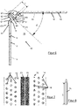
- figure 1 shows two drywalls 100, 200 meeting at an angle of 90° ⁇ 10°.
- An end face 110 of a first wall 100 abuts a longitudinal side 205 of a second wall 200 approximately at right angles in such a way that a gap 34 forms between them.
- material 250 for example some plaster of paris or an insulating material, which originally adheres to the face 110 of the first wall 100, for example.
- this material 250 often detaches from this end face 210, as a result of which the plaster 400, which adheres both to the wall 200 and to the material 250 in the joint 34, is increasingly under tension.
- the plaster 400 tears and forms an essentially vertical but irregularly jagged, ugly crack 600 in the area of the corner of the room between the two walls.
- a profile 300 is shown, which is typically made of thin sheet aluminum or galvanized steel. It has a leg 302 which is fixed to a longitudinal side 105 of a first wall 100, for example with plaster of paris or screws. Material 250 in joint 34 is formed with a second Leg 304 of the profile 300 on the end face 110 of the wall 100 is clamped. When plastering, the plaster 400, 402 is applied to both walls 100, 200 up to the corner of the room and thus also to the leg 302 of the profile 300.
- the Figures 3a and 3b show another profile 300, which is typically also made of a thin aluminum sheet or galvanized steel sheet.
- the metal sheet is bent and has a flat limb 302 for attachment to the longitudinal side 105 of the first wall 100 and a second limb projecting at right angles therefrom, which is bent over in a U-shape to form a groove nose 304 .
- the profile 300 is bent in such a way that the groove nose 304 extends into the joint 34 after proper assembly, with its groove being accessible from the outside.
- the leg 302 is fastened to the long side 105 of the first wall 100, for example with plaster or screws, and the material 250 located in the joint 34, for example insulating material, plaster, rough plaster, if available, is pressed against the end face with the groove 304 projecting at right angles from it 110 of the first wall 100 pressed.
- the plaster 400, 402 is applied to both walls 100, 200 up to the corner of the room and thus also to the leg 302 of the profile 300.
- the plaster 400, 402 on the walls 100, 200 has dried, the plaster 400 is cut in the area of the groove nose 304, for example with a knife, so that a shadow gap 800 is created.
- shadow gaps 800 Another disadvantage of the shadow gaps 800 is that the shadow gap 800 cannot be created arbitrarily, perpendicular to the aesthetically desired wall of a room, but is created depending on how the room walls are joined (cf. Figure 3b ).
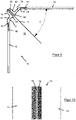
- Figures 4 and 5 show a special ceiling profile 300 ', which is similar to the profile 300 from the Figures 3a, 3b has a first leg 302 and a groove nose 304 projecting at right angles therefrom.
- a pull-out edge band 306 is clamped in the groove nose 304 , which protrudes from the groove nose 304 to such an extent that it projects beyond this first leg 302 at right angles to the first leg 302 .
- the edge band 306 is made of plastic, while the leg 302 with the groove nose 304 projecting at right angles is either made of an aluminum sheet or sheet steel or made of plastic.
- the first leg 302 of the ceiling profile 300 ′ is fastened to the ceiling 500 in such a way that the groove nose 304 projects into the joint 34 .
- the joint 34 is free of material, so that the groove nose 304 rests directly on the end face 510 of the ceiling 500 .
- the edge band 306 protrudes from the joint 34 .
- the plaster 402 is applied to the ceiling 500 and up to the edge band 306 on the leg 302 of the ceiling joint band 300'.
- the edge band 306 jammed in the groove nose 304 is pulled out of the groove.
- the plaster 402 of the ceiling 500 has a straight, clean edge.
- the disadvantage here is that the walls 100 that adjoin the ceiling 500 can only be plastered after the ceiling plaster 402 has completely dried and the edge band 306 has been stripped off, which entails a considerable loss of time.
- ceiling movement bearings 106 are usually provided in the upper area of non-load-bearing walls 100. These run horizontally in the wall 100 and should theoretically be approximately level with the lower surface 505 of the ceiling 500 . Due to formwork errors when concreting such ceilings 500 however, the ceiling movement bearings 106 are often in the range 1 cm to 2 cm below the lower surface 505 of the ceiling 500 in the wall 100, as shown in FIGS Figures 4 and 5 is shown.
- the U.S. 2002/0023399 A1 relates, for example, to a stucco trim assembly for application to a corner defined by the junction of a pair of walls to allow a foam and/or stucco material to be controllably applied and adjustably secured to the walls.
- the assembly includes an elongate female trim member attachable to a corner of the pair of walls and an elongate inserted frame clip. The clip is adjustably supported at a distance from the wall in the elongate female trim member.
- the object of the invention is therefore to provide an aid and to present a method which, using the aid, makes it possible to produce standard-compliant plaster joints with clean, straight edges.
- the production of the aid should be simple and inexpensive.
- the handling of the tool should be easy and should lead to the desired result of a clean, straight, standard-compliant plaster joint even without many years of experience on the part of the person doing the work.
- the tool for creating standard-compliant joints is a joint strip system that is intended to be attached in the area of a joint between two walls arranged approximately at right angles to one another.
- the joint strip system comprises a separating strip and a joint strip with a connecting element and two strip legs which are connected to one another using the connecting element.
- the connecting element connects the two strip legs to one another in such a way that they enclose an angle z′ of 90° ⁇ 10° with one another for assembly, in which case they open up a space between them.
- the connecting element has a groove which, for assembly, accommodates the separating strip in such a way that it can later be removed from the groove again.
- the groove has a groove opening which opens the groove to space and it has a virtual groove center plane which is oriented between the slat legs in space at an angle x' of 45° ⁇ 5° to each of the slat legs.
- a first slat leg of the two slat legs is intended to be fixed on a space-facing surface of a first wall of the two walls arranged at right angles, and a second slat leg of the two slat legs is intended to be fixed on a space-facing surface of the second wall of the two walls to be fixed.
- the connecting element has two connecting flanges lying in a flange plane, which connect the strip legs to one another.
- the strip legs and the flange plane enclose an angle v' of 135° ⁇ 5°.
- the groove with its groove opening separates the two connecting flanges from one another.
- the groove opening is delimited laterally, for example, by a respective delimiting lug which, if connecting flanges are present, protrudes beyond the connecting flanges (62, 64) in the direction of the room.
- the connecting element has a central body in which the groove is integrated, the groove having a groove bottom which is arranged on the groove center plane and opposite the groove opening.
- the groove bottom is designed in such a way that it can be severed.
- the central body is provided with a thickening in which the groove is integrated and which extends in the opposite direction to space with respect to the plane of the flange.
- the central body or its thickening is adapted in its dimensions to the length of the connecting flanges in such a way that it can be placed between the walls in the joint without touching one of the two walls if each of the strip legs is on one of these two walls is attached.
- skirting limbs have a width of at least 2cm ⁇ 0.3cm, this ensures that potential hazards that could cause a crack in the plaster are covered by the skirting limbs, so that their risk potential is minimized.
- the joint strip can be manufactured very easily and inexpensively from an amorphous or partially crystalline thermoplastic or duroplast; preferably made of a plastic from the following group: polymer containing chlorine, polymer containing styrene, polyester polyamide, polyvinyl chloride, PVC-U - hard, PVC-P - soft.
- the separating strip is made from a low-energy plastic or a non-polar polymer, in particular if it is made from a polyolefin or polyethylene.
- the joint strip is equipped with a positioning aid for particularly easy handling of the joint strip system.
- the method for producing the plaster joint comprises the following steps: Fixing a first strip leg on a first wall of the two walls, fixing a second strip leg on a second wall of the two walls, the order being irrelevant; apply plaster on the first wall and the first strip leg up to the separating strip protruding from the joint strip between the strip legs, plastering on the second wall and the second strip leg up to the separating strip, the order again being arbitrary; Allow plaster to dry on both walls and when plaster is properly dry pull the separating strip out of the joint strip and separate the grooved bottom of the joint strip.
- the plaster is only applied to the two walls up to the delimiting lugs on the strip legs and the connecting flanges.
- the plaster is only applied up to a thickness that corresponds to the height of the delimiting lugs above the connecting flanges.
- the delimiting lugs are noticeable working aids during plastering, which can advantageously be used for a good adjustment of the plaster thickness. Then the other steps are carried out as described above up to the separation of the groove bottom.
- a joint strip system that has a positioning aid
- the joint strip is first placed with the leg side that has the positioning aid on the first wall, so that the positioning aid engages behind the edge of the first wall, while the strip leg is flat against the room facing surface of the first wall.
- the first strip leg is fixed in this position on the first wall.
- the second leg of the strip is placed flat against the surface of the second wall facing the room and fixed there. then the other steps are carried out as described above up to the separation of the groove bottom.
- FIGS Figures 12 to 15 are examples of different embodiments of a joint strip 10 of a joint strip system 1 (see 12 ) described in detail.
- figure 8 shows a separating strip 24 of the joint strip system 1 according to the invention and in FIGS Figures 12 to 15 the use of the joint strip system 1 according to the invention is shown.
- a joint strip 10 of the joint strip system 1 is equipped with a first strip leg 12 and a second strip leg 14 which are connected to one another via a connecting element 16 .
- the connecting element 16 of the joint strip 10 is used on the one hand to connect the strip legs 12, 14 to one another, but also to accommodate a separating strip 24 (see FIG 8, 12, 13 ).
- the connecting element 16 With a thickened center body 62, the connecting element 16 is in a joint 34 between two walls 30, 32 to be plastered (see Fig Figures 12 to 15 ) placeable.
- the strip legs 12, 14 are used to fix the joint strip 10 to the walls 30, 32 to be plastered.
- the strip legs 12, 14 are fastened to the wall 30 , 32 attached. In this way, the joint strip 10 is secured against slipping and it is ensured that the separating strip 24 of the joint strip system 1 is guided approximately vertically and in a straight line along the joint 34 between the walls 30, 32 in the assembled state.
- the strip legs 12, 14 have holes 18, 18'.
- the holes 18, 18' are continuous and, in the example shown here, are arranged regularly distributed over the respective strip legs 12, 14. However, it is just as conceivable for the holes 18, 18' to be arranged randomly scattered over the respective strip leg (not shown). Holes 18, 18' in the strip legs are advantageous if the strip legs 12, 14 are to be fastened to the wall substrate (base material of the wall or rough plaster) with plaster, for example, or for fixing with screws. Also conceivable are embodiments of the joint strip 10 with one or two hole-free strip legs 12, 14(compare Figures 9 and 10 ), ie at least one strip leg 12 or 14 which is designed without any holes 18, 18'.
- a joint strip 10 with holes 18, 18' in the strip legs 12, 14 or one without holes or one with only one strip leg of the holes depends on the nature of the plaster 40, 42 for plastering a Wall 30, 32 is to be used, the nature of the material of the bar legs 12, 14, and / or the nature of the substrate to which the plaster is to be applied.
- the connecting element 16, which connects the two strip legs 12, 14 to one another, can be formed in one piece with the strip legs 12, 14, as in the example of FIG Figures 6 and 7 is shown, or be manufactured separately, as in the Figures 9 and 10 is shown.
- the connecting element 16 advantageously has a thickened central body 62 with a groove 20 that is preferably arranged in the middle.
- the groove 20 has a groove bottom 67 and a groove opening 61 opposite the groove bottom 67.
- a virtual groove center plane 21 separates the groove 20 into two virtual halves.
- the strip legs 12, 14 and the virtual groove center plane 21 each form an angle x' of approximately 45° ⁇ 5.
- the connecting element 16 connects in the examples shown here, the two strip legs 12, 14 thus at a defined angle z 'of about 90 ° ⁇ 10 °, the Bar legs 12, 14 enclose a space 26 between them.
- An angle v' of 135° ⁇ 5° is provided between the flange plane 65 and the angled area of the connecting flanges 62, 64, so that the strip legs 12, 14 adjoining the connecting flanges 62, 64 linearly at an angle z' of 90° ⁇ 10° to each other.
- the central body 62 is preferably located off-center with respect to the two connecting flanges 64,66. Rather, the central body 62 with the groove opening 61 is preferably offset from the center, somewhat closer to the angling point 8 of the first connecting flange 64 than to the angling point 9 of the second connecting flange 64. In other words: a distance 8' from the angling point 8 of the first connecting flange 62 to the groove center plane 21 is smaller than a distance 9' from the bend point 9 of the second connecting flange 64 to the groove center plane 21.
- the ratio of the two distances 8'/9' is approximately in the range of 2/5 to 1/2 and preferably 1/3. In a preferred embodiment, for example, the distance 8' is 1mm ⁇ 0.1mm and the distance 9' is 3mm ⁇ 0.1mm.
- the groove bottom 67 in the thickening of the central body 62 has a thickness 6 which is small compared to the thickness 7 of the side walls of the groove 20 (cf. 11 ),
- the ratio of the thickness 7 of the groove base to the thickness of the groove side wall is, for example, only about 1/5 to 1/2, in particular about 1/3, depending on the material of the central body 62.
- the central body 62 protrudes from the flange plane 65 on one side with its thickening having the groove base 67 .
- This part of the central body 62 is intended to be placed in the joint 34 between the walls 30, 32, 50 to be plastered. Its dimensions are adapted to the length of the connecting flanges 64, 66 in such a way that it can be placed in the joint 34 without touching one of the two walls 30, 32 or 50, 32 when each of the strip legs 12, 14 is on one of these two walls 30, 32 and 50, 32 respectively.
- a positioning aid 22 is provided on a strip leg or connecting flange. This also aids in the positioning of the thickening of the central body in the joint 34 such that the central body 16 is arranged without contact with each wall 30,32,50.
- the positioning aid 22 is preferably designed in such a way that it forms a stop which can engage behind an edge between the longitudinal side and the end face of the corresponding wall 30, 32, 50.
- the positioning aid 22 can be in the form of a shoulder (see FIG 6 , 9 , 11-15 ) which is arranged on that side of the strip legs or the connecting flanges which faces away from the space 26 between the strip legs 12, 14 in the angled region thereof.
- the positioning aid is preferably 22 arranged on that side relative to the groove center plane 21 which has the shorter distance 8', 9' between the bend point 8, 9 and the groove center plane 21.
- the groove opening 61 of the groove 20 is arranged on that side of the central body 62 which is opposite the groove base 67 and opens the groove 20 into the space 26 opening between the strip legs 12, 14.
- the sidewalls of groove 20 are an integral part of centerbody 62.
- these side walls terminate flush with the connecting flanges 62, 64 or their surfaces pointing in the opening direction on the side of the groove opening 61.
- the side walls protrude beyond the connecting flanges 62, 64 in the direction of the groove opening 61, so that they form two delimiting lugs 68, 69 laterally delimiting the groove opening 61.
- a separating strip 24, as shown in 8 is shown in plan view, clamped in the groove 20.
- the delimiting lugs 68, 69 prevent plaster from entering the groove 20 and ensure that the separating strip 24 can be easily separated from the groove 20 after the plaster 40, 42 has dried. This is particularly advantageous if relatively thin plaster is used for plastering.
- the groove 20 in the central body 62 of the connecting element 16 serves to accommodate the separating strip 24.
- the width 2 of the groove 20 and the thickness 4 of the separating strip 24 are matched to one another in such a way that the separating strip 24 can pass through during assembly and in the assembled state frictional forces is held firmly in the groove 24, but can be removed from it by hand ( 6 and 11 to 14 ).
- the width 5 of the separating bar 24 is matched to the depth 3 of the groove 20 that the separating bar 24, when it is introduced into the groove 20 up to the groove bottom 67, protrudes beyond the groove opening 61 or the delimiting lugs 68, 69 protrudes, if such available.
- That part of the separating strip 24 which protrudes beyond the groove opening 61 or delimiting lugs 68, 69 is dimensioned such that, after the plaster 40, 42 has been applied, it protrudes from the plaster so far, for example, that it can be easily gripped with fingers or pliers , for example normal combination pliers or flat nose pliers (see 13 ). It therefore preferably protrudes by at least 3 mm, or in other words, the width 5 of the separating strip 24 is 0 mm to 10 mm, better 0.2 mm to 5 mm, in particular 3 mm to 3.5 mm, greater than the depth 3 of the groove 20; each preferably with a tolerance of about ⁇ 0.1mm.
- the width 5 of the separating strip 24 is not greater than the depth 3 of the groove 20 and should still be easy to remove later, it must not be inserted into the groove 20 up to the bottom 67 of the groove. It is nevertheless advantageous for the stability of the strip if it is at least as wide as the groove is deep.
- the strip legs 12, 14 and the connecting element 16 of the joint strip 10 are preferably made of the same material, because this makes production easier.
- the one-piece design also simplifies production.
- connecting element 16 and strip legs 12, 14 in the form of separate components can also be advantageous, since this increases the possible uses and makes use more flexible.
- Figures 9 and 10 an example of such an embodiment of the joint strip is shown.
- To the bar legs 12, 14 with There are various options for connecting the connecting flanges 64, 66, which are illustrated with reference to these figures for the sake of simplicity, although in reality only one of the connection options is usually implemented in a joint strip 10.
- the connecting element 16 made of a flexible, ie reversibly deformable plastic in this example has a fork-like structure in the angled area of its first connecting flange 62, into which a correspondingly tapered section of the strip leg 12 can be inserted.
- Fork and tapered bar section are designed in such a way that the holding function is ensured solely by frictional forces.
- a snap-in lug (not shown) of one element can engage in a corresponding material recess in the other component (bar section or fork), so that the holding function is ensured either solely by a snap mechanism or in addition to the frictional force by a snap mechanism.
- the fork and the tapered strip section or connecting flange 62 and strip leg 12 are advantageously designed in such a way that, when they are plugged together, there is a smooth, continuous transition between the connecting flange 62 and the strip leg 12 as far as their surfaces are concerned.
- connecting flange 66 and strip leg 14 on oppositely formed, thinner end sections 82, 84 which are designed so that they form an even, continuous transition between connecting flange 66 and strip leg 14 when placed on top of each other, preferably on all surfaces. It is irrelevant whether the connecting flange 64 has a material cutout on the side facing the wall 32 or the strip leg 14. The respective other component correspondingly has the material cutout on the side facing away from the wall 32. For gluing the strip leg 14 to the connecting flange 66, adhesive is applied to the mutually facing sides of those component sections 82, 84 which have the material recess, before these sections 82, 84 are then joined together.
- the component sections 82, 84 arranged one on top of the other are connected to one another with the material recess by means of plastic welding.
- Advantageous materials for the joint strip 10 are synthetic materials, preferably plastics.
- thermoplastics and duroplastics are suitable, especially if they are also amorphous or partially crystalline. Good results have been achieved with polymers containing chlorine and styrene as well as with polyester polyamides, such as polyvinyl chloride, PVC-U - hard, PVC-P - soft.
- the bar legs 12, 14 and the connecting element 16 can also consist of different plastics.
- the connecting element can be made of a more flexible plastic than the strip legs. The production then takes place, for example, in a multi-component injection molding process or in the form of separate components in separate process steps or completely separate processes.
- the connecting element 16 is manufactured separately, it is also conceivable to manufacture the connecting element 16 from plastic, e.g an aluminum sheet or an aluminum alloy sheet. In such a case, the connecting element 16 and the strip leg 12, 14 can also be connected to one another by a plug-in connection 80 based on friction and/or with a snap mechanism, or by an adhesive connection.
- plastic e.g an aluminum sheet or an aluminum alloy sheet.
- the connecting element 16 and the strip leg 12, 14 can also be connected to one another by a plug-in connection 80 based on friction and/or with a snap mechanism, or by an adhesive connection.
- the separating strip 24 is preferably made of a low-energy plastic or a non-polar polymer. Soft to hard thermoplastics and elastomers as well as thermoplastic elastomers are suitable here. Polyolefins and polyethylene have proven to be very suitable.
- the joint strip 1 is preferably adjustable in length to the length of the respective wall joint 34 for which it is to be used. This also applies to the separating strip 24, which is preferably brought to the same length as the joint strip 1 or the joint 34 for assembly.
- the connecting element 16 and the strip legs 12, 14 of the joint strip 10 have in the embodiments of Figures 6.7 and 9.10 all the same length.
- the groove 20 also extends over the entire length of the joint strip 10. It is also conceivable - and this both if the strip legs 62, 64 and the connecting element 16 are manufactured separately and if they are manufactured in one piece - that the connecting element 16 consists of several individual, preferably identically configured connecting sections 16', 16'', 16′′′, which connect the strip legs 62, 64 along the length of the joint strip at a distance from one another (cf Fig.16 ), which saves material.
- strip legs 12, 14, which are used for attachment to the wall being designed in the form of individual strip leg sections 12', 12'', 14', 14''. This also results in material savings (see 17 ).
- the joint strip 10 can be in the form of rolled-up goods.
- the depth of the groove 20 is preferably - in each case with a tolerance of about ⁇ 0.1 mm, in a range from 0.5 mm to 7 mm; as A range of 3mm to 6mm has proven to be advantageous and in particular 5.3mm or 5.4mm or 5.5mm depending on whether there are limiting lugs 68, 69 or not and depending on the material pairing of the central body 62 and the separating strip 24.
- the width 2 of the Groove 20 is about 0.2mm-5mm in particular at 1mm-2mm with a tolerance of about ⁇ 0.1mm.
- the delimiting lugs 68, 69 have a height of about 0mm to 3mm, in particular 1.5mm-2mm, even better 1mm, each with a tolerance of ⁇ 0.1mm.
- the material thickness of the groove bottom 67 also depends on the material of the central body 62 and is in the range of 0.1mm ⁇ 0.1mm to 0.5mm ⁇ 0.1mm and in particular 0.3mm ⁇ 0.1mm.
- the length of the strip legs 12, 14 or the distance from the end of the respective strip leg 12, 14 to the bending point 8, 9 of the transition area of the associated connecting flange 62, 64 is between 15mm ⁇ 3mm and 40mm ⁇ 3mm; better between 25mm ⁇ 3mm and 35mm ⁇ 3mm and especially at 30mm ⁇ 3mm.
- the two strip legs can be of the same length or one of the two strip legs can also be somewhat shorter than the other strip leg. In the in the Figures 6 and 7 In the illustrated embodiment, for example, the first strip leg 12 is about 5 mm to 3 mm shorter than the second strip leg 14, which is about 30 mm long.
- the advantage of the same length strip legs is the simple manufacture and handling.
- slat legs of unequal length is the greater flexibility when it comes to being able to cover potential danger points, such as ceiling movement bearings 106, with at least one slat leg (see Figures 4 and 5 state of the art and 15 the solution presented here).
- the same joint strip system can be used for rough plaster.
- the dimensions are preferably somewhat larger here.
- the length of the slat legs is 20mm-70mm better in the range of 35mm-60mm better at 50mm each with a tolerance of up to about 3mm;
- the depth 3 of the groove 20 is preferably 2mm-25mm with a tolerance of about ⁇ 0.1mm, the width 2 of the groove 20 is about 0.5mm-10mm with a tolerance of about ⁇ 0.1mm.
- the limiting lugs 68, 69 have a height of about 0mm to 5mm ⁇ 0.1mm.
- the dimensions of the separating strip 24 are matched to the groove and any delimiting lugs that may be present.
- Joint strip 10 and separating strip 24 are used as joint strip system 1 for processing on site, i.e. separating strip 24 is fixed in groove 20 of joint strip 10 for assembly by frictional force.
- the embodiment shown in the figures has a shoulder in the angled area of the first connecting flange 64, which serves as a positioning aid 22, and during assembly in the joint 34 between the two walls 30, 32 with the edge of the first wall 30 can be brought into abutment, so that the shoulder 22 engages behind the wall 30 ( figure 12 ). It is also conceivable to provide the shoulder 22 as a component of the first strip leg 12 instead of in the angled area of the first connecting flange 64 .
- connection elements and strip legs are separate. It is of course also conceivable to provide positioning aids 22 on both sides of the joint strip 10 .
- the joint strip system 1 is shown in the assembled state.
- the separating strip 24 is inserted in the groove 20 of the connecting element 16.
- the thickening of the middle body 62 of the connecting element 16 with the groove 20 is introduced into the joint 34 between the walls 30, 32, which in this example meet perpendicularly, in such a way that the shoulder 22 trained positioning an edge of the first wall 30 engages behind.
- the strip legs 12, 14 are fixed to the walls 30, 32 with clamps 36 or with nails 38 or screws, thereby securing the joint strip 10 in the described position and against slipping.
- FIG. 13 shows the installed joint strip system 1 12 with applied plaster 40, 42.
- the plaster 40, 42 - marked here with the reference numerals 40', 42' - penetrates into the holes 18, 18', which may result in a better hold of the Plaster 40, 42 on the joint strip 10 results.
- the plaster is applied to both walls 30, 32 and the parts of the joint strip 10 mounted on the walls 30, 32 in such a way that the plaster 40, 42 the respective wall 30, 32, the strip leg 12, 14 of the joint strip 10, as well in each case the transition from the joint strip 10 to the wall 30, 32 and the connecting flanges 62, 64 to the limiting lugs 68, 69 covered.
- the separating strip 24 projects out of the plaster 40, 42 so that it can be easily grasped with the fingers or pliers.
- the delimiting lugs 68, 69 can be easily felt when plastering and therefore also serve as a "thickness mark". This means that plaster is applied in a thickness until the outer surface of the delimiting lugs 68, 69 can be felt.
- the bottom of the groove 67 of the joint strip 10 is severed with a suitable tool, for example a sharp knife, in particular a carpet knife.
- a suitable tool for example a sharp knife, in particular a carpet knife.
- the joint strip system 1 also in the area of joints 34 between 50 ceilings and 32 side walls.
- the joint strip 10 with the separating strip 24 is fastened with its one strip leg 12 to the ceiling 50 and with its other strip leg 14 to the wall 32 (or vice versa, depending on the design of the joint 34 between ceiling and wall).
- the strip legs 12, 14 are designed so wide (between 2.5 cm and 3.5 cm) that they normally cover the ceiling movement bearings 106 in the wall 32. After the wall 32 has been plastered, plastering of the ceiling 50 can be started immediately. There is no need to wait for the plaster on the wall to dry.
- the separating strip 24 is pulled out of the groove 20 of the joint strip 10 and the bottom of the groove 67 is severed.
- the result is a plaster joint 70 that is straight over the entire length and reliably separates the plaster 40, 42 from the ceiling 50 and wall 32. It is aesthetically beautiful, always oriented at the same angle to space, namely at an angle of 45° ⁇ 5°. In addition, stresses and ugly horizontal cracks in the upper area of the wall are avoided by covering one strip leg 14 over the ceiling movement bearing 106 in the wall 32.
- the joint strip system 1 presented here prevents the plastering compound from getting behind the joint strip 10 . This ensures that movements, stresses and cracks in the wall behind the joint strip cannot be transferred to the plaster on the joint strip.
Landscapes
- Engineering & Computer Science (AREA)
- Architecture (AREA)
- Civil Engineering (AREA)
- Structural Engineering (AREA)
- Building Environments (AREA)
Claims (12)
- Système de couvre-joint (1) conçu pour être placé au niveau d'un joint (34) entre deux parois (30, 32, 50) disposées à peu près à angle droit, comprenant un couvre-joint (10) avec deux bras (12, 14) perpendiculaires l'un à l'autre et une bande de séparation (24), dans lequel le couvre-joint (10) présente un élément de liaison (16), lequel élément de liaison (16)a) relie entre eux les deux bras du couvre-joint (12, 14) de telle sorte que ceux-ci forment, pour le montage, un angle z' de 90° ± 10° l'un avec l'autre et délimitent un espace (26) entre eux ;b) présente une gorge (20) qui reçoit la bande de séparation (24) pour le montage de telle façon qu'elle puisse être retirée plus tard de la gorge (20), cette gorge (20) présentant une ouverture de gorge (61) qui ouvre la gorge (20) vers l'espace (26) et cette gorge (20) présentant un plan médian de gorge virtuel (21) qui est orienté dans l'espace (26) entre les bras du couvre-joint (12, 14) selon un angle x' de 45° ± 5° par rapport à chacun des bras du couvre-joint (12, 14),dans lequel un premier bras du couvre-joint (12) parmi les deux bras du couvre-joint (12, 14) est conçu pour être fixé sur une surface de la première paroi (30, 50) tournée vers l'espace (26) et un deuxième bras du couvre-joint (14) parmi les deux bras du couvre-joint (12, 14) est conçu pour être fixé sur une surface de la deuxième paroi (32, 50) tournée vers l'espace (26), dans lequel l'élément de liaison (16) présente un corps médian (62) dans lequel la gorge (20) est intégrée, dans lequel la gorge (20) présente un fond de gorge (67) qui est disposé sur le plan médian de la gorge (21) en face de l'ouverture de gorge (61) et le fond de gorge (67) est conformé, du point de vue de son matériau et de son épaisseur de matériau (6), de façon à pouvoir être sectionné,caractérisé en ce que l'élément de liaison (16) présente deux brides de liaison (64, 66) qui se trouvent dans le même plan de bride (65), qui relient les bras du couvre-joint (12, 14) entre eux, les bras du couvre-joint (12, 14) et le plan de bride (65) formant un angle v' de 135° ± 5° et la gorge (20) séparant les deux brides de liaison (62, 64) avec son ouverture de gorge (61), etle corps médian (62) présente une partie épaissie dans laquelle la gorge (20) est intégrée, la partie épaissie s'étendant par rapport au plan de bride (65) dans la direction opposée vers l'espace (26) et le fond de gorge (67) présentant, dans la partie épaissie du corps médian (62) une épaisseur (6) inférieure à l'épaisseur (7) des parois latérales de la gorge (20).
- Système de couvre-joint (1) selon la revendication 1, caractérisé en ce que l'ouverture de gorge (61) est délimitée latéralement par des ergots de délimitation (68, 69) de chaque côté, qui dépassent des brides de liaison (62, 64) en direction de l'espace (26).
- Système de couvre-joint (1) selon la revendication 1 ou 2, caractérisé en ce que le corps médian (62) a des dimensions adaptées à la longueur des brides de liaison (64, 66) de telle manière qu'il puisse être placé dans le joint (34) entre les parois (30, 32, 50) sans toucher l'une de deux parois (30, 32, 50) quand chacun des bras du couvre-joint (12, 14) est fixé à l'une de ces deux parois (30, 32, 50).
- Système de couvre-joint (1) selon l'une des revendications 1 à 3, caractérisé en ce que le plan médian de la gorge (21) est perpendiculaire au plan de bride (65).
- Système de couvre-joint (1) selon l'une des revendications 1 à 4, caractérisé en ce que le bras du couvre-joint (12, 14) présente une largeur d'au moins 2 cm ± 0,3 cm, en particulier de 3 cm ± 0,3 cm pour les enduits fins et 5 cm ± 0,3 cm à 10 cm ± 0,3 cm, en particulier de 7 cm ± 0,3 cm pour les crépis.
- Système de couvre-joint (1) selon l'une des revendications 1 à 5, caractérisé en ce que le couvre-joint (10) est fait d'un matériau thermoplastique ou thermodurcissable amorphe ou partiellement cristallin, de préférence d'un plastique appartenant au groupe qui comprend : polymère chloré, polymère contenant du styrène, polyester, polyamide, polychlorure de vinyle, PVC-U dur, PVC-P souple.
- Système de couvre-joint (1) selon l'une des revendications 1 à 6, caractérisé en ce que la bande de séparation (24) est faite d'un plastique à basse énergie ou d'un polymère apolaire, en particulier d'une polyoléfine ou de polyéthylène.
- Système de couvre-joint (1) selon l'une des revendications 1 à 7, caractérisé en ce que le couvre-joint (10) est moulé d'une pièce.
- Système de couvre-joint (1) selon l'une des revendications 1 à 8, caractérisé en ce que le couvre-joint (10) présente une aide au positionnement (22).
- Procédé pour la fabrication d'un joint sous enduit (70) avec un système de couvrejoints (1) selon l'une des revendications 1 à 9, comprenant les étapes suivantes :a) fixation d'un premier bras du couvre-joint (12) sur une première paroi (30, 50),b) fixation d'un deuxième bras du couvre-joint (14) sur une deuxième paroi (32),c) application de l'enduit (40) sur la première paroi (30, 50) et le premier bras du couvre-joint (12) jusqu'à une bande de séparation (24) qui dépasse du couvre-joint (10) entre les bras du couvre-joint (12, 14),d) application de l'enduit (42) sur la deuxième paroi (32) et le deuxième bras du couvre-joint (14) jusqu'à la bande de séparation (24),e) séchage de l'enduit (40, 42),f) retrait de la bande de séparation (24) du couvre-joint,g) séparation du fond de gorge (67).
- Procédé selon la revendication 10, caractérisé en ce qu'un système de couvre-joint (1) selon l'une des revendications 2 à 9 est mis en œuvre et l'enduit (40, 42) n'est appliqué sur les deux parois (30, 32, 50) que jusqu'aux ergots de délimitation (68, 69) sur les bras du couvre-joint (12, 14) et aux brides de liaison (64, 66) et seulement sur une épaisseur correspondant à la hauteur des ergots de délimitation (68, 69) au-dessus des brides de liaison (64, 66), les ergots de délimitation (68, 69) étant de préférence utilisés pendant l'application de l'enduit comme des aides au travail perceptibles sous la main pour indiquer l'épaisseur de l'enduit.
- Procédé selon l'une des revendications 10 ou 11, caractérisé en ce qu'un système de couvre-joint (1) selon la revendication 9 est mis en œuvre et le couvre-joint (10) est disposé par rapport aux parois (30, 32, 50) de telle manière que l'aide au positionnement (22) passe derrière un bord de l'une de ces parois (30, 32, 50).
Priority Applications (1)
| Application Number | Priority Date | Filing Date | Title |
|---|---|---|---|
| EP18214520.1A EP3670781B1 (fr) | 2018-12-20 | 2018-12-20 | Système de fourniture des joints |
Applications Claiming Priority (1)
| Application Number | Priority Date | Filing Date | Title |
|---|---|---|---|
| EP18214520.1A EP3670781B1 (fr) | 2018-12-20 | 2018-12-20 | Système de fourniture des joints |
Publications (2)
| Publication Number | Publication Date |
|---|---|
| EP3670781A1 EP3670781A1 (fr) | 2020-06-24 |
| EP3670781B1 true EP3670781B1 (fr) | 2022-06-15 |
Family
ID=64755161
Family Applications (1)
| Application Number | Title | Priority Date | Filing Date |
|---|---|---|---|
| EP18214520.1A Active EP3670781B1 (fr) | 2018-12-20 | 2018-12-20 | Système de fourniture des joints |
Country Status (1)
| Country | Link |
|---|---|
| EP (1) | EP3670781B1 (fr) |
Families Citing this family (2)
| Publication number | Priority date | Publication date | Assignee | Title |
|---|---|---|---|---|
| DE102020112180A1 (de) | 2020-05-06 | 2021-11-11 | Sven Brunner | Verfahren zur Ausbildung einer Innenecke zwischen wenigstens zwei winklig aneinander angrenzenden Bauplatten eines Wandaufbaus, insbesondere eines Wandaufbaus eines in Holzrahmenbauweise oder Holztafelbauweise gefertigten Fertighauses |
| CN113700254B (zh) * | 2021-08-26 | 2023-04-25 | 广东威法定制家居股份有限公司 | 一种护墙板系统 |
Family Cites Families (2)
| Publication number | Priority date | Publication date | Assignee | Title |
|---|---|---|---|---|
| DE9106457U1 (de) * | 1991-05-25 | 1991-08-08 | Migua Hammerschmidt GmbH, 5603 Wülfrath | Vorrichtung zum Abdichten der Fuge zwischen zwei Wandbauteilen |
| US6647679B2 (en) * | 1999-06-22 | 2003-11-18 | Michael Belleau | Stucco trim assembly |
-
2018
- 2018-12-20 EP EP18214520.1A patent/EP3670781B1/fr active Active
Also Published As
| Publication number | Publication date |
|---|---|
| EP3670781A1 (fr) | 2020-06-24 |
Similar Documents
| Publication | Publication Date | Title |
|---|---|---|
| DE1658864A1 (de) | Dehnungsfugenabdeckung | |
| EP3256666B1 (fr) | Bande d'étanchéité de jointure universelle pour différentes dimensions de profilé et dispositif d'étanchéité pourvu d'une telle bande d'étanchéité de jointure | |
| EP2063047A1 (fr) | Système de rails profilés | |
| CH688158A5 (de) | Vorrichtung zur Befestigung von Apparaten und Gegenstaenden auf einer aussenisolierten Gebaeudefassade und dgl. | |
| EP3670781B1 (fr) | Système de fourniture des joints | |
| DE102016012946A1 (de) | Vorrichtung zur Erleichterung der Anbringung von Hilfsmitteln zur Herstellung einer oberen Begrenzung einer Wandöffnung im Bauwesen | |
| DE20008712U1 (de) | Profilleiste zum Abdichten einer Bewegungsfuge zwischen einem Bauteil und einer Putzschicht | |
| AT513517B1 (de) | Vorrichtung zur Justierung und Befestigung von Sockelleisten | |
| DE4103088C2 (de) | Vorrichtung zur Ausbildung gleichmäßig verlaufender, vorstehender Kanten an Gebäudeoberflächen | |
| WO2012004220A2 (fr) | Plaques perforées à base de plâtre et procédé de pose de ces plaques | |
| EP0918127B1 (fr) | Châssis de porte et dispositif de montage | |
| EP3293323A1 (fr) | Système de montage pour plinthe à plancher ou profil de plinthe | |
| EP0566134A1 (fr) | Moyens pour la fixation invisible d'un profil | |
| EP1001103A2 (fr) | Profilé de bordure pour revêtement de mur | |
| DE19709428A1 (de) | Anputzleiste für Fensterstöcke, Türstöcke oder dergleichen am Übergang zu Putz | |
| DE2016834A1 (de) | Vorrichtung zur Anbringung von Wandabdeckungen | |
| DE10015124A1 (de) | Bauplattenbefestiger und -verbinder | |
| DE19948468A1 (de) | Kasten für Rolläden oder dergleichen | |
| DE202008003267U1 (de) | Sockelleiste | |
| EP2530227A1 (fr) | Charnière à fixations affleurantes pour éléments de vitrerie | |
| DE102008041731A1 (de) | Vorrichtung zum Herstellen einer Schattenfuge | |
| DE3127743A1 (de) | "sockelleiste" | |
| AT16912U1 (de) | Putzprofilleiste | |
| DE102009016917B3 (de) | Montage-Hilfswerkzeug und Verfahren zur Montage von Bauplatten an eine Unterkonstruktion | |
| DE9312779U1 (de) | Befestigungsvorrichtung für Paneele |
Legal Events
| Date | Code | Title | Description |
|---|---|---|---|
| PUAI | Public reference made under article 153(3) epc to a published international application that has entered the european phase |
Free format text: ORIGINAL CODE: 0009012 |
|
| STAA | Information on the status of an ep patent application or granted ep patent |
Free format text: STATUS: THE APPLICATION HAS BEEN PUBLISHED |
|
| AK | Designated contracting states |
Kind code of ref document: A1 Designated state(s): AL AT BE BG CH CY CZ DE DK EE ES FI FR GB GR HR HU IE IS IT LI LT LU LV MC MK MT NL NO PL PT RO RS SE SI SK SM TR |
|
| AX | Request for extension of the european patent |
Extension state: BA ME |
|
| STAA | Information on the status of an ep patent application or granted ep patent |
Free format text: STATUS: REQUEST FOR EXAMINATION WAS MADE |
|
| 17P | Request for examination filed |
Effective date: 20201218 |
|
| RBV | Designated contracting states (corrected) |
Designated state(s): AL AT BE BG CH CY CZ DE DK EE ES FI FR GB GR HR HU IE IS IT LI LT LU LV MC MK MT NL NO PL PT RO RS SE SI SK SM TR |
|
| GRAP | Despatch of communication of intention to grant a patent |
Free format text: ORIGINAL CODE: EPIDOSNIGR1 |
|
| STAA | Information on the status of an ep patent application or granted ep patent |
Free format text: STATUS: GRANT OF PATENT IS INTENDED |
|
| INTG | Intention to grant announced |
Effective date: 20220110 |
|
| GRAS | Grant fee paid |
Free format text: ORIGINAL CODE: EPIDOSNIGR3 |
|
| GRAA | (expected) grant |
Free format text: ORIGINAL CODE: 0009210 |
|
| STAA | Information on the status of an ep patent application or granted ep patent |
Free format text: STATUS: THE PATENT HAS BEEN GRANTED |
|
| AK | Designated contracting states |
Kind code of ref document: B1 Designated state(s): AL AT BE BG CH CY CZ DE DK EE ES FI FR GB GR HR HU IE IS IT LI LT LU LV MC MK MT NL NO PL PT RO RS SE SI SK SM TR |
|
| REG | Reference to a national code |
Ref country code: CH Ref legal event code: EP Ref country code: GB Ref legal event code: FG4D Free format text: NOT ENGLISH |
|
| REG | Reference to a national code |
Ref country code: IE Ref legal event code: FG4D Free format text: LANGUAGE OF EP DOCUMENT: GERMAN |
|
| REG | Reference to a national code |
Ref country code: DE Ref legal event code: R096 Ref document number: 502018009913 Country of ref document: DE |
|
| REG | Reference to a national code |
Ref country code: AT Ref legal event code: REF Ref document number: 1498496 Country of ref document: AT Kind code of ref document: T Effective date: 20220715 |
|
| REG | Reference to a national code |
Ref country code: LT Ref legal event code: MG9D |
|
| REG | Reference to a national code |
Ref country code: NL Ref legal event code: MP Effective date: 20220615 |
|
| PG25 | Lapsed in a contracting state [announced via postgrant information from national office to epo] |
Ref country code: SE Free format text: LAPSE BECAUSE OF FAILURE TO SUBMIT A TRANSLATION OF THE DESCRIPTION OR TO PAY THE FEE WITHIN THE PRESCRIBED TIME-LIMIT Effective date: 20220615 Ref country code: NO Free format text: LAPSE BECAUSE OF FAILURE TO SUBMIT A TRANSLATION OF THE DESCRIPTION OR TO PAY THE FEE WITHIN THE PRESCRIBED TIME-LIMIT Effective date: 20220915 Ref country code: LT Free format text: LAPSE BECAUSE OF FAILURE TO SUBMIT A TRANSLATION OF THE DESCRIPTION OR TO PAY THE FEE WITHIN THE PRESCRIBED TIME-LIMIT Effective date: 20220615 Ref country code: HR Free format text: LAPSE BECAUSE OF FAILURE TO SUBMIT A TRANSLATION OF THE DESCRIPTION OR TO PAY THE FEE WITHIN THE PRESCRIBED TIME-LIMIT Effective date: 20220615 Ref country code: GR Free format text: LAPSE BECAUSE OF FAILURE TO SUBMIT A TRANSLATION OF THE DESCRIPTION OR TO PAY THE FEE WITHIN THE PRESCRIBED TIME-LIMIT Effective date: 20220916 Ref country code: FI Free format text: LAPSE BECAUSE OF FAILURE TO SUBMIT A TRANSLATION OF THE DESCRIPTION OR TO PAY THE FEE WITHIN THE PRESCRIBED TIME-LIMIT Effective date: 20220615 Ref country code: BG Free format text: LAPSE BECAUSE OF FAILURE TO SUBMIT A TRANSLATION OF THE DESCRIPTION OR TO PAY THE FEE WITHIN THE PRESCRIBED TIME-LIMIT Effective date: 20220915 |
|
| PG25 | Lapsed in a contracting state [announced via postgrant information from national office to epo] |
Ref country code: RS Free format text: LAPSE BECAUSE OF FAILURE TO SUBMIT A TRANSLATION OF THE DESCRIPTION OR TO PAY THE FEE WITHIN THE PRESCRIBED TIME-LIMIT Effective date: 20220615 Ref country code: LV Free format text: LAPSE BECAUSE OF FAILURE TO SUBMIT A TRANSLATION OF THE DESCRIPTION OR TO PAY THE FEE WITHIN THE PRESCRIBED TIME-LIMIT Effective date: 20220615 |
|
| PG25 | Lapsed in a contracting state [announced via postgrant information from national office to epo] |
Ref country code: NL Free format text: LAPSE BECAUSE OF FAILURE TO SUBMIT A TRANSLATION OF THE DESCRIPTION OR TO PAY THE FEE WITHIN THE PRESCRIBED TIME-LIMIT Effective date: 20220615 |
|
| PG25 | Lapsed in a contracting state [announced via postgrant information from national office to epo] |
Ref country code: SM Free format text: LAPSE BECAUSE OF FAILURE TO SUBMIT A TRANSLATION OF THE DESCRIPTION OR TO PAY THE FEE WITHIN THE PRESCRIBED TIME-LIMIT Effective date: 20220615 Ref country code: SK Free format text: LAPSE BECAUSE OF FAILURE TO SUBMIT A TRANSLATION OF THE DESCRIPTION OR TO PAY THE FEE WITHIN THE PRESCRIBED TIME-LIMIT Effective date: 20220615 Ref country code: RO Free format text: LAPSE BECAUSE OF FAILURE TO SUBMIT A TRANSLATION OF THE DESCRIPTION OR TO PAY THE FEE WITHIN THE PRESCRIBED TIME-LIMIT Effective date: 20220615 Ref country code: PT Free format text: LAPSE BECAUSE OF FAILURE TO SUBMIT A TRANSLATION OF THE DESCRIPTION OR TO PAY THE FEE WITHIN THE PRESCRIBED TIME-LIMIT Effective date: 20221017 Ref country code: ES Free format text: LAPSE BECAUSE OF FAILURE TO SUBMIT A TRANSLATION OF THE DESCRIPTION OR TO PAY THE FEE WITHIN THE PRESCRIBED TIME-LIMIT Effective date: 20220615 Ref country code: EE Free format text: LAPSE BECAUSE OF FAILURE TO SUBMIT A TRANSLATION OF THE DESCRIPTION OR TO PAY THE FEE WITHIN THE PRESCRIBED TIME-LIMIT Effective date: 20220615 Ref country code: CZ Free format text: LAPSE BECAUSE OF FAILURE TO SUBMIT A TRANSLATION OF THE DESCRIPTION OR TO PAY THE FEE WITHIN THE PRESCRIBED TIME-LIMIT Effective date: 20220615 |
|
| PG25 | Lapsed in a contracting state [announced via postgrant information from national office to epo] |
Ref country code: PL Free format text: LAPSE BECAUSE OF FAILURE TO SUBMIT A TRANSLATION OF THE DESCRIPTION OR TO PAY THE FEE WITHIN THE PRESCRIBED TIME-LIMIT Effective date: 20220615 Ref country code: IS Free format text: LAPSE BECAUSE OF FAILURE TO SUBMIT A TRANSLATION OF THE DESCRIPTION OR TO PAY THE FEE WITHIN THE PRESCRIBED TIME-LIMIT Effective date: 20221015 |
|
| REG | Reference to a national code |
Ref country code: DE Ref legal event code: R097 Ref document number: 502018009913 Country of ref document: DE |
|
| PG25 | Lapsed in a contracting state [announced via postgrant information from national office to epo] |
Ref country code: AL Free format text: LAPSE BECAUSE OF FAILURE TO SUBMIT A TRANSLATION OF THE DESCRIPTION OR TO PAY THE FEE WITHIN THE PRESCRIBED TIME-LIMIT Effective date: 20220615 |
|
| PLBE | No opposition filed within time limit |
Free format text: ORIGINAL CODE: 0009261 |
|
| STAA | Information on the status of an ep patent application or granted ep patent |
Free format text: STATUS: NO OPPOSITION FILED WITHIN TIME LIMIT |
|
| PG25 | Lapsed in a contracting state [announced via postgrant information from national office to epo] |
Ref country code: DK Free format text: LAPSE BECAUSE OF FAILURE TO SUBMIT A TRANSLATION OF THE DESCRIPTION OR TO PAY THE FEE WITHIN THE PRESCRIBED TIME-LIMIT Effective date: 20220615 |
|
| 26N | No opposition filed |
Effective date: 20230316 |
|
| PG25 | Lapsed in a contracting state [announced via postgrant information from national office to epo] |
Ref country code: SI Free format text: LAPSE BECAUSE OF FAILURE TO SUBMIT A TRANSLATION OF THE DESCRIPTION OR TO PAY THE FEE WITHIN THE PRESCRIBED TIME-LIMIT Effective date: 20220615 |
|
| GBPC | Gb: european patent ceased through non-payment of renewal fee |
Effective date: 20221220 |
|
| REG | Reference to a national code |
Ref country code: BE Ref legal event code: MM Effective date: 20221231 |
|
| PG25 | Lapsed in a contracting state [announced via postgrant information from national office to epo] |
Ref country code: LU Free format text: LAPSE BECAUSE OF NON-PAYMENT OF DUE FEES Effective date: 20221220 |
|
| PG25 | Lapsed in a contracting state [announced via postgrant information from national office to epo] |
Ref country code: IE Free format text: LAPSE BECAUSE OF NON-PAYMENT OF DUE FEES Effective date: 20221220 Ref country code: GB Free format text: LAPSE BECAUSE OF NON-PAYMENT OF DUE FEES Effective date: 20221220 |
|
| PG25 | Lapsed in a contracting state [announced via postgrant information from national office to epo] |
Ref country code: FR Free format text: LAPSE BECAUSE OF NON-PAYMENT OF DUE FEES Effective date: 20221231 Ref country code: BE Free format text: LAPSE BECAUSE OF NON-PAYMENT OF DUE FEES Effective date: 20221231 |
|
| PG25 | Lapsed in a contracting state [announced via postgrant information from national office to epo] |
Ref country code: IT Free format text: LAPSE BECAUSE OF FAILURE TO SUBMIT A TRANSLATION OF THE DESCRIPTION OR TO PAY THE FEE WITHIN THE PRESCRIBED TIME-LIMIT Effective date: 20220615 |
|
| PG25 | Lapsed in a contracting state [announced via postgrant information from national office to epo] |
Ref country code: HU Free format text: LAPSE BECAUSE OF FAILURE TO SUBMIT A TRANSLATION OF THE DESCRIPTION OR TO PAY THE FEE WITHIN THE PRESCRIBED TIME-LIMIT; INVALID AB INITIO Effective date: 20181220 |
|
| PG25 | Lapsed in a contracting state [announced via postgrant information from national office to epo] |
Ref country code: CY Free format text: LAPSE BECAUSE OF FAILURE TO SUBMIT A TRANSLATION OF THE DESCRIPTION OR TO PAY THE FEE WITHIN THE PRESCRIBED TIME-LIMIT Effective date: 20220615 |
|
| PG25 | Lapsed in a contracting state [announced via postgrant information from national office to epo] |
Ref country code: MK Free format text: LAPSE BECAUSE OF FAILURE TO SUBMIT A TRANSLATION OF THE DESCRIPTION OR TO PAY THE FEE WITHIN THE PRESCRIBED TIME-LIMIT Effective date: 20220615 |
|
| PG25 | Lapsed in a contracting state [announced via postgrant information from national office to epo] |
Ref country code: MC Free format text: LAPSE BECAUSE OF FAILURE TO SUBMIT A TRANSLATION OF THE DESCRIPTION OR TO PAY THE FEE WITHIN THE PRESCRIBED TIME-LIMIT Effective date: 20220615 |
|
| PG25 | Lapsed in a contracting state [announced via postgrant information from national office to epo] |
Ref country code: TR Free format text: LAPSE BECAUSE OF FAILURE TO SUBMIT A TRANSLATION OF THE DESCRIPTION OR TO PAY THE FEE WITHIN THE PRESCRIBED TIME-LIMIT Effective date: 20220615 Ref country code: MC Free format text: LAPSE BECAUSE OF FAILURE TO SUBMIT A TRANSLATION OF THE DESCRIPTION OR TO PAY THE FEE WITHIN THE PRESCRIBED TIME-LIMIT Effective date: 20220615 |
|
| PG25 | Lapsed in a contracting state [announced via postgrant information from national office to epo] |
Ref country code: MT Free format text: LAPSE BECAUSE OF FAILURE TO SUBMIT A TRANSLATION OF THE DESCRIPTION OR TO PAY THE FEE WITHIN THE PRESCRIBED TIME-LIMIT Effective date: 20220615 |
|
| PG25 | Lapsed in a contracting state [announced via postgrant information from national office to epo] |
Ref country code: BG Free format text: LAPSE BECAUSE OF FAILURE TO SUBMIT A TRANSLATION OF THE DESCRIPTION OR TO PAY THE FEE WITHIN THE PRESCRIBED TIME-LIMIT Effective date: 20220615 |
|
| PG25 | Lapsed in a contracting state [announced via postgrant information from national office to epo] |
Ref country code: BG Free format text: LAPSE BECAUSE OF FAILURE TO SUBMIT A TRANSLATION OF THE DESCRIPTION OR TO PAY THE FEE WITHIN THE PRESCRIBED TIME-LIMIT Effective date: 20220615 |
|
| PGFP | Annual fee paid to national office [announced via postgrant information from national office to epo] |
Ref country code: CH Payment date: 20250101 Year of fee payment: 7 |
|
| REG | Reference to a national code |
Ref country code: CH Ref legal event code: U11 Free format text: ST27 STATUS EVENT CODE: U-0-0-U10-U11 (AS PROVIDED BY THE NATIONAL OFFICE) Effective date: 20260101 |
|
| PGFP | Annual fee paid to national office [announced via postgrant information from national office to epo] |
Ref country code: AT Payment date: 20251222 Year of fee payment: 8 |
|
| PGFP | Annual fee paid to national office [announced via postgrant information from national office to epo] |
Ref country code: DE Payment date: 20251230 Year of fee payment: 8 |