EP3672024A1 - Vorrichtung und verfahren zum steuern der aufladung und entladung von batterien einer gruppe solcher batterien - Google Patents
Vorrichtung und verfahren zum steuern der aufladung und entladung von batterien einer gruppe solcher batterien Download PDFInfo
- Publication number
- EP3672024A1 EP3672024A1 EP19217597.4A EP19217597A EP3672024A1 EP 3672024 A1 EP3672024 A1 EP 3672024A1 EP 19217597 A EP19217597 A EP 19217597A EP 3672024 A1 EP3672024 A1 EP 3672024A1
- Authority
- EP
- European Patent Office
- Prior art keywords
- battery
- batteries
- power source
- discharge
- recharging
- Prior art date
- Legal status (The legal status is an assumption and is not a legal conclusion. Google has not performed a legal analysis and makes no representation as to the accuracy of the status listed.)
- Pending
Links
Images


Classifications
-
- H—ELECTRICITY
- H02—GENERATION; CONVERSION OR DISTRIBUTION OF ELECTRIC POWER
- H02J—ELECTRIC POWER NETWORKS; CIRCUIT ARRANGEMENTS OR SYSTEMS FOR SUPPLYING OR DISTRIBUTING ELECTRIC POWER; SYSTEMS FOR STORING ELECTRIC ENERGY
- H02J7/00—Circuit arrangements for charging or discharging batteries or for supplying loads from batteries
- H02J7/50—Circuit arrangements for charging or discharging batteries or for supplying loads from batteries acting upon multiple batteries simultaneously or sequentially
- H02J7/52—Circuit arrangements for charging or discharging batteries or for supplying loads from batteries acting upon multiple batteries simultaneously or sequentially for charge balancing, e.g. equalisation of charge between batteries
- H02J7/56—Active balancing, e.g. using capacitor-based, inductor-based or DC-DC converters
-
- H—ELECTRICITY
- H02—GENERATION; CONVERSION OR DISTRIBUTION OF ELECTRIC POWER
- H02J—ELECTRIC POWER NETWORKS; CIRCUIT ARRANGEMENTS OR SYSTEMS FOR SUPPLYING OR DISTRIBUTING ELECTRIC POWER; SYSTEMS FOR STORING ELECTRIC ENERGY
- H02J7/00—Circuit arrangements for charging or discharging batteries or for supplying loads from batteries
- H02J7/50—Circuit arrangements for charging or discharging batteries or for supplying loads from batteries acting upon multiple batteries simultaneously or sequentially
-
- H—ELECTRICITY
- H02—GENERATION; CONVERSION OR DISTRIBUTION OF ELECTRIC POWER
- H02J—ELECTRIC POWER NETWORKS; CIRCUIT ARRANGEMENTS OR SYSTEMS FOR SUPPLYING OR DISTRIBUTING ELECTRIC POWER; SYSTEMS FOR STORING ELECTRIC ENERGY
- H02J7/00—Circuit arrangements for charging or discharging batteries or for supplying loads from batteries
- H02J7/34—Parallel operation in networks using both storage and other DC sources, e.g. providing buffering
- H02J7/35—Parallel operation in networks using both storage and other DC sources, e.g. providing buffering with light sensitive cells
-
- H—ELECTRICITY
- H02—GENERATION; CONVERSION OR DISTRIBUTION OF ELECTRIC POWER
- H02J—ELECTRIC POWER NETWORKS; CIRCUIT ARRANGEMENTS OR SYSTEMS FOR SUPPLYING OR DISTRIBUTING ELECTRIC POWER; SYSTEMS FOR STORING ELECTRIC ENERGY
- H02J7/00—Circuit arrangements for charging or discharging batteries or for supplying loads from batteries
- H02J7/50—Circuit arrangements for charging or discharging batteries or for supplying loads from batteries acting upon multiple batteries simultaneously or sequentially
- H02J7/585—Sequential battery discharge in systems with a plurality of batteries
-
- H—ELECTRICITY
- H02—GENERATION; CONVERSION OR DISTRIBUTION OF ELECTRIC POWER
- H02J—ELECTRIC POWER NETWORKS; CIRCUIT ARRANGEMENTS OR SYSTEMS FOR SUPPLYING OR DISTRIBUTING ELECTRIC POWER; SYSTEMS FOR STORING ELECTRIC ENERGY
- H02J7/00—Circuit arrangements for charging or discharging batteries or for supplying loads from batteries
- H02J7/875—Charging or discharging for charge maintenance, battery initiation or rejuvenation
-
- H—ELECTRICITY
- H02—GENERATION; CONVERSION OR DISTRIBUTION OF ELECTRIC POWER
- H02J—ELECTRIC POWER NETWORKS; CIRCUIT ARRANGEMENTS OR SYSTEMS FOR SUPPLYING OR DISTRIBUTING ELECTRIC POWER; SYSTEMS FOR STORING ELECTRIC ENERGY
- H02J7/00—Circuit arrangements for charging or discharging batteries or for supplying loads from batteries
- H02J7/90—Regulation of charging or discharging current or voltage
- H02J7/92—Regulation of charging or discharging current or voltage with prioritisation of loads or sources
-
- H—ELECTRICITY
- H02—GENERATION; CONVERSION OR DISTRIBUTION OF ELECTRIC POWER
- H02J—ELECTRIC POWER NETWORKS; CIRCUIT ARRANGEMENTS OR SYSTEMS FOR SUPPLYING OR DISTRIBUTING ELECTRIC POWER; SYSTEMS FOR STORING ELECTRIC ENERGY
- H02J2101/00—Supply or distribution of decentralised, dispersed or local electric power generation
- H02J2101/20—Dispersed power generation using renewable energy sources
- H02J2101/22—Solar energy
- H02J2101/24—Photovoltaics
-
- H—ELECTRICITY
- H02—GENERATION; CONVERSION OR DISTRIBUTION OF ELECTRIC POWER
- H02J—ELECTRIC POWER NETWORKS; CIRCUIT ARRANGEMENTS OR SYSTEMS FOR SUPPLYING OR DISTRIBUTING ELECTRIC POWER; SYSTEMS FOR STORING ELECTRIC ENERGY
- H02J2101/00—Supply or distribution of decentralised, dispersed or local electric power generation
- H02J2101/20—Dispersed power generation using renewable energy sources
- H02J2101/28—Wind energy
-
- H—ELECTRICITY
- H02—GENERATION; CONVERSION OR DISTRIBUTION OF ELECTRIC POWER
- H02J—ELECTRIC POWER NETWORKS; CIRCUIT ARRANGEMENTS OR SYSTEMS FOR SUPPLYING OR DISTRIBUTING ELECTRIC POWER; SYSTEMS FOR STORING ELECTRIC ENERGY
- H02J9/00—Circuit arrangements for emergency or stand-by power supply, e.g. for emergency lighting
- H02J9/04—Circuit arrangements for emergency or stand-by power supply, e.g. for emergency lighting in which the distribution system is disconnected from the normal source and connected to a standby source
- H02J9/06—Circuit arrangements for emergency or stand-by power supply, e.g. for emergency lighting in which the distribution system is disconnected from the normal source and connected to a standby source with automatic change-over, e.g. UPS systems
- H02J9/061—Circuit arrangements for emergency or stand-by power supply, e.g. for emergency lighting in which the distribution system is disconnected from the normal source and connected to a standby source with automatic change-over, e.g. UPS systems for DC powered loads
-
- H—ELECTRICITY
- H02—GENERATION; CONVERSION OR DISTRIBUTION OF ELECTRIC POWER
- H02J—ELECTRIC POWER NETWORKS; CIRCUIT ARRANGEMENTS OR SYSTEMS FOR SUPPLYING OR DISTRIBUTING ELECTRIC POWER; SYSTEMS FOR STORING ELECTRIC ENERGY
- H02J9/00—Circuit arrangements for emergency or stand-by power supply, e.g. for emergency lighting
- H02J9/04—Circuit arrangements for emergency or stand-by power supply, e.g. for emergency lighting in which the distribution system is disconnected from the normal source and connected to a standby source
- H02J9/06—Circuit arrangements for emergency or stand-by power supply, e.g. for emergency lighting in which the distribution system is disconnected from the normal source and connected to a standby source with automatic change-over, e.g. UPS systems
- H02J9/066—Circuit arrangements for emergency or stand-by power supply, e.g. for emergency lighting in which the distribution system is disconnected from the normal source and connected to a standby source with automatic change-over, e.g. UPS systems characterised by the use of dynamo-electric machines
-
- Y—GENERAL TAGGING OF NEW TECHNOLOGICAL DEVELOPMENTS; GENERAL TAGGING OF CROSS-SECTIONAL TECHNOLOGIES SPANNING OVER SEVERAL SECTIONS OF THE IPC; TECHNICAL SUBJECTS COVERED BY FORMER USPC CROSS-REFERENCE ART COLLECTIONS [XRACs] AND DIGESTS
- Y02—TECHNOLOGIES OR APPLICATIONS FOR MITIGATION OR ADAPTATION AGAINST CLIMATE CHANGE
- Y02B—CLIMATE CHANGE MITIGATION TECHNOLOGIES RELATED TO BUILDINGS, e.g. HOUSING, HOUSE APPLIANCES OR RELATED END-USER APPLICATIONS
- Y02B10/00—Integration of renewable energy sources in buildings
- Y02B10/70—Hybrid systems, e.g. uninterruptible or back-up power supplies integrating renewable energies
-
- Y—GENERAL TAGGING OF NEW TECHNOLOGICAL DEVELOPMENTS; GENERAL TAGGING OF CROSS-SECTIONAL TECHNOLOGIES SPANNING OVER SEVERAL SECTIONS OF THE IPC; TECHNICAL SUBJECTS COVERED BY FORMER USPC CROSS-REFERENCE ART COLLECTIONS [XRACs] AND DIGESTS
- Y02—TECHNOLOGIES OR APPLICATIONS FOR MITIGATION OR ADAPTATION AGAINST CLIMATE CHANGE
- Y02E—REDUCTION OF GREENHOUSE GAS [GHG] EMISSIONS, RELATED TO ENERGY GENERATION, TRANSMISSION OR DISTRIBUTION
- Y02E10/00—Energy generation through renewable energy sources
- Y02E10/50—Photovoltaic [PV] energy
- Y02E10/56—Power conversion systems, e.g. maximum power point trackers
Definitions
- the invention relates to the general field of rechargeable electric storage batteries. It relates more particularly to the electrical supply of electronic devices located in areas without a reliable electrical network, in other words, without an electrical network which meets strict requirements in terms of availability and stability of current, voltage and / or power supplied.
- a first solution consists in using generator sets, for example diesel engines producing electrical energy.
- the generator sets are generally oversized in relation to the power of use of the consumer devices which they supply, which leads to a fairly low efficiency and to premature wear of the generator set.
- the powers of use required to supply telecommunications equipment and air conditioning equipment are each of the order of 1 to 4 kW.
- the average charge rate of a generator that powers these two pieces of equipment is only between 10 and 50%.
- a second solution consists in associating a battery with a generator to form a hybrid HGB supply system (for "Hybrid Genset Battery" in English). Two phases are alternated: during a first phase, the generator supplies the consumer devices and also charges the battery, then during a second phase, the generator is switched off and the battery discharges to supply the consumer devices. The first and second phases can each last a few hours.
- This solution makes it possible to extend the life of the generator by reducing its operating time, the cost of its maintenance and by making it operate at a higher charge rate (since it supplies the battery in addition to the consumer devices), ideally 75% for lower fuel consumption.
- a third solution for supplying consumer electronic devices consists in associating a battery with the unreliable electrical network: the battery is charged and is kept charged as long as the electrical network is available at the same time as the consumer devices are supplied by this electrical network, and when the electrical network is no longer available, the battery discharges to supply the consumer devices with autonomy for several hours.
- REDOX or “flow” batteries such as oxidation-reduction vanadium salt flow batteries have the advantage of being able to add capacity by increasing the size of an external liquid reservoir. But these batteries have a modest yield in permanent use because of electrical leaks between elements in series via the conductive saline fluids used and they require a lot of maintenance. For example, the REDOX Zinc-Brome battery must be stopped once a week for its regeneration and internal automatic cleaning. In addition, it has not been proposed to operate alternating REDOX batteries with another power source.
- the consumer device is supplied without interruption, in other words continuously, either by the power source or by the discharge of a battery.
- a recharge and a rest, or a discharge and a rest are simultaneous or carried out simultaneously if they start at the same time and end at the same time.
- the invention thus makes it possible to supply the consumer device in a continuous manner (i.e. without interruption) either by the power source or by at least one of the batteries among the set of batteries. Putting the batteries to rest is introduced without reducing the supply to the consumer device.
- putting a battery to rest is its disconnection from any power source and from any consumer device. During this phase, a battery charge level remains constant.
- recharging a battery is a phase during which the battery is supplied electrically by the power source and stores electrical energy. During this phase, the battery charge level increases.
- the recharging of a battery further comprises an opening of said electrical circuit for discharging this battery.
- the discharge of a battery is a phase during which the battery restores electrical energy, to supply the consumer device. During this phase, the battery charge level decreases.
- the charging and discharging circuits of a battery can be controlled independently of each other.
- the nominal capacity and voltage values of a battery are those defined by the battery manufacturer in accordance with a standard.
- a cycle of a battery comprises at least one recharging and one discharging of this battery.
- each battery of the assembly can be connected to one or more power sources and to one or more consumer devices.
- a battery can comprise a single branch or several branches of the same voltage operating in parallel and made of blocks.
- a battery can have two branches in parallel of 48V, each branch having four blocks of 12V each.
- the invention makes it possible in particular to extend the lifespan of the batteries thanks to the rest time which separates the recharging and discharging phases and / or vice versa. Indeed, the batteries of the assembly are recharged or discharged alternately.
- the batteries in the set can have different nominal capacities or the same nominal capacity.
- Putting a battery to rest can reduce the temperature of the battery, which improves its lifespan, but also reduces the need to turn on battery cooling equipment, such as an air conditioner.
- the invention therefore makes it possible to reduce energy consumption.
- At least one battery of said assembly is of the Lithium type.
- the Lithium battery offers deep cycles, works between 80 and 100% of nominal capacity, and has a longer lifespan than other types of batteries.
- the extension of the service life of the Lithium battery thanks to the solution proposed by the present invention allows a return on the investment on the initial cost of the Lithium battery.
- At least one battery of said set is of the Lithium or Nickel type (for example NiCd, NiZn or NiMH) accepting sufficient power in recharge and in discharge so that a single battery of said set can on the one hand all of the power requested by the consumer device and on the other hand, accept the maximum power of the power source.
- Lithium or Nickel type for example NiCd, NiZn or NiMH
- the capacity of the battery assembly according to the invention can be equal to the capacity of a single battery in accordance with a supply solution of the prior art.
- the fact of having a set of at least two batteries does not result in an increase in the cost of the batteries compared to the solutions of the prior art.
- the rest is not systematically added after each recharge and after each discharge. It is possible to put a battery to rest after each recharge of this battery for example, or after each discharge, or after a given number of cycles. The gain in terms of battery life decreases as this number of cycles increases.
- the invention therefore makes it possible to extend the life of this battery.
- the invention therefore makes it possible to supply the consumer device with one of the discharged batteries while extending the life of each of the alternating batteries.
- control method further comprises a step of monitoring information representative of a state of activity of the power source. As long as the state of the power source is active, recharging of the first battery is implemented up to a determined charge level, the consumer device being powered by the power source. As long as the state of the power source is inactive, the discharge of the first battery is implemented up to a determined charge level.
- control method according to the invention further comprises a step of obtaining at least one item of information representative of a level of charge of a battery of the assembly in order to determine the battery in charge. or in landfill.
- the determination of the battery to which a recharge or discharge is applied is then based on precise information on the charge level of each battery, which reduces the risk of selecting a battery which is not sufficiently charged for discharge. to be able to power the consumer device or to select for recharging a battery which already has a high charge level when there is another battery in greater need of recharging.
- the information representative of a charge level of a battery can be obtained for example by physical measurements, or by estimates such as calculations made by machine learning algorithms.
- determining a battery to which a recharge or discharge is applied is done systematically alternately between the different batteries of the set based on a stopwatch for example, or on an availability period from the power source.
- the discharge circuit of each of the batteries performs a diode function to avoid a circulation current between the batteries. It is recalled that such an inter-battery circulation current can occur when the batteries are not at the same charge level, and when the charging circuit or the discharging circuit of a first battery is closed simultaneously with the closing. of the discharge circuit of a second battery. It can be noted that this inter-battery circulation current can be much higher than the discharge current of the batteries, and can therefore destroy them.
- Such an inter-battery current would be 10 times higher than the discharge and charge current (33A) observed in 3h mode.
- This example represents a common use case for hybrid systems of the HGB type.
- the invention makes it possible to avoid such a circulation current between the batteries. It protects the batteries and extends their lifespan.
- control method according to the invention further comprises a step of controlling the power source to put it in the active state or in the inactive state. According to this mode, the information representative of the activity state of the power source is provided by this source control step.
- the power source is therefore only turned on when a battery needs to be recharged. This mode therefore makes it possible to reduce energy consumption, in particular the consumption of fuels when the power source is a generator. In addition, this mode allows you to control the performance of the power source, reduce its start-up time and the risk of premature wear and therefore extend the life of the power source.
- a duration of activity and a duration of inactivity of the power source are determined beforehand; in other words, these durations are predefined.
- the durations of activity and inactivity can be determined at constant values.
- the control step can consist of activating or deactivating the power source in an alternating fashion and according to the durations of the activity and the inactivity. This mode allows for simple and periodic control.
- the duration of activity and the duration of inactivity of the power source are determined as a function of the at least one item of information representative of the level of charge of a battery.
- This embodiment makes it possible to optimize the gains in terms of lifetimes of the batteries and of the power source since it is based on information on the charge levels of the batteries. This mode also makes it possible to guarantee the availability of power for the consumer device.
- control device further comprises a communication module configured to obtain at least information representative of a charge level of a battery, to determine a battery to be recharged or discharged .
- control device further comprises a control module configured to control the state of activity of the power source, the monitoring module being configured to obtain, from the control, the information representative of the state of activity of the power source.
- the electrical recharging and discharging circuits corresponding to a battery of the assembly are included in the control device, or in the same physical box as the control device. In another mode, these electrical circuits are not part of the control device, but are controlled by the coupling module of the control device.
- the operating control device is such that the consumer device is supplied either by the power source or by the discharge of a battery.
- the power source is an electric generator, a generator, a solar panel or a wind turbine. Several types of sources are then possible.
- the consumer device is a wireless communications base station or a medical device.
- the invention can therefore be implemented for uninterruptible powering of telecommunications equipment and ensuring coverage of a telecommunications network in areas which do not have a reliable electrical network, such as rural areas or areas with difficult geographic, climatic or economic conditions.
- the invention can also be implemented in order to supply without interruption, i.e. without interruption, in such areas, medical devices having very high requirements in terms of supply availability, requiring for example permanent availability.
- the invention can also be implemented to supply, in such areas, other devices with less demanding constraints.
- the invention also relates to a computer program on a recording medium, this program being capable of being implemented in a computer or in a control device according to the invention, this program comprising instructions adapted to the implementation of a control method as described above.
- This program can use any programming language, and be in the form of machine code, source code, object code, or intermediate code between source code and object code, such as in a partially compiled form, or in n ' any other desirable form.
- this program can be executed by a microcontroller ⁇ C ("micro-Controller" in English).
- the invention also relates to information or recording media readable by a computer, and comprising instructions of the computer program as mentioned above.
- the information or recording media can be any entity or device capable of storing the programs.
- the supports may include a storage means, such as a ROM, for example a CD ROM or a microelectronic circuit ROM, or else a magnetic recording means, for example a floppy disc or a disc. hard, or flash memory.
- the information or recording media can be transmissible media such as an electrical or optical signal, which can be routed via an electrical or optical cable, by radio link, by wireless optical link or by other ways.
- the program according to the invention can in particular be downloaded from a network of the Internet type.
- each information or recording medium can be an integrated circuit in which the program is incorporated, the circuit being adapted to execute or to be used in the execution of the control method according to the invention.
- the power source is a generator group forming with the batteries B1 and B2 a hybrid power supply system of the HGB type.
- the two batteries B1 and B2 are of the Lithium type.
- the BTS consumer device is a base station of a telecommunications network.
- the control system is located in a rural area without an electrical network. A permanent power supply to the BTS consumer device is required to ensure network coverage in this rural area.
- the DP control device implements a control method according to the invention for controlling the recharging and discharging of the batteries B1 and B2.
- RECT rectifiers to “rectify” in English
- RECT rectifiers are placed at the output of the source GE to convert an alternating current AC generated by the source GE into a direct current DC.
- the figure 2 is a flowchart representing, in general, steps of a method, according to the invention, for controlling a set E of batteries.
- the method is implemented by a DP control device according to the invention.
- control device DP controls a set of two batteries B1 and B2.
- the control device D and the assembly E are included in a control system as presented by the figure 1 .
- the method is initiated during a step E200, considering for example that the last battery Bi having been put to rest is the battery B1 and that the power source GE is initially in an active state.
- the index "i" is a positive integer between 1 and the number of batteries in the set E, that is to say between 1 and 2 in this example, initialized during step E200 to the value 1.
- Battery B1 can be considered as the last battery to be put to rest because its charge level is lower than that of battery B2.
- control device DP monitors info-disp information representative of the state of activity of the power source GE.
- the monitoring step E202 is included in a loop Bcl which includes a step E203 waiting for a TIMER duration between two successive iterations of the monitoring step E202.
- the control device DP continues to command the recharging of the battery B1 (E204) and the return to rest of the battery B2 (E206).
- control device DP obtains information MESi indicating whether the level of charge of the battery on recharge B1 (E204) has reached the determined level NR MIN .
- step E208 is followed by recharging E204 of the battery B1 and putting E206 to rest. of battery B2.
- the control device changes the value of the index i during a step E210 and again executes the monitoring step E202.
- the index i relates to the last battery having been put to rest, which is in this example of implementation, the battery B2.
- the command device DP commands, the recharging E204 of the battery B2 up to the determined level of charge NR MIN and putting E206 of battery B1 to rest.
- the change E210 of the index i is an incrementation by a unit if i is strictly less than the number n of batteries, or an assignment of the value 1 if i is equal to n.
- control device DP obtains, during a step E220, information MESi indicating that the charge level of the discharged battery B1 (E216) has reached the determined level ND MIN , the control device changes the value of the index i during step E210 and again executes the monitoring step E202.
- the DP device alternately changes the battery to be recharged (E204) or discharged (E216), and therefore the battery to be put to rest (E206 or E218).
- the monitoring step E202 is repeated in a loop according to a countdown timer with a TIMER duration.
- the monitoring step E202 can be triggered on reception of a message sent by another device.
- the monitoring step E202 can be triggered following a change E210 in the value of the index i.
- the control device DP puts the two batteries B1 and B2 at rest.
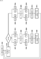
- the figure 3 is a flowchart representing steps of a method for controlling a set E of two batteries B1 and B2 in accordance with an embodiment of the invention. The method is implemented by the DP control device according to the invention and included in the control system described with reference to the figure 1 .
- the consumer device BTS is supplied either by the generator GE, or by one of the batteries B1 or B2.
- control device DP controls the batteries B1 and B2 of the assembly E, but also the state of activity of the generator GE.
- the method is initiated during a step E300.
- the GE generator set is initially stopped.
- the control device DP obtains info-disp information representative of the state of activity of the power source GE, this information being provided in this example by the control device itself . This information indicates that the GE source is in the inactive state.
- the device DP controls the electrical circuits corresponding to the battery B1 for its discharge E002 up to a determined charge level ND MIN considered to be low, for example of 0%.
- the device DP puts the battery B2 to rest, by controlling the opening of the charging and discharging circuits corresponding to the battery B2 for putting it to rest E004.
- control device DP receives information mesl representative of the level of charge of the battery B1. This information indicates that the charge level of battery B1 has reached the charge level ND MIN of 0%.
- the device DP commands a discharge E010 of the battery B2 up to a determined charge level ND MIN considered to be low, for example of 0%.
- the consumer device BTS is then supplied by the battery B2.
- the control device DP commands the battery E1 to be put to rest E008, simultaneously with the discharge E010.
- the control device DP receives second information mes2 representative of the level of charge of the battery B2. This information indicates that the charge level of battery B2 has reached the determined charge level ND MIN of 0%.
- the consumer device BTS is then supplied directly by the power source GE.
- step E302 the info-disp information then indicates that the activity state of the power source GE is active.
- the last battery to be put to rest (E008) is battery B1. Consequently, the device DP commands a recharge E016 of this battery B1 up to a determined charge level NR MIN considered to be high, for example of 100%, and simultaneously, a resting E018 of the battery B2.
- the generator GE supplies both the consumer device BTS and a battery among B1 and B2.
- the control device DP receives information mes1 representative of the charge level of the battery B1, this information indicating that this battery B1 is charged at the level NR MIN considered to be high, of 100%.
- the device DP On receipt of this mesl information, the device DP simultaneously controls a standby E022 of the battery B1 and a recharge E024 of the battery B2 up to a determined charge level NR MIN , for example of 100%.
- control device DP receives information mes2 representative of the charge level of the battery B2, this information indicating that this battery B2 is charged at the determined high level NR MIN of 100%.
- control device DP controls during a step E028 the deactivation of the source GE.
- each of the two batteries B1 and B2 is put to rest between each recharge and each discharge.
- control device DP stops the source GE (E208) only when all the batteries B1 and B2 have charge levels considered to be high.
- control device DP can stop the source GE as soon as the charge level of one of the batteries B1 or B2 is considered to be high.
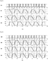
- the figure 4 is a timing diagram representing the different stages of the control process in accordance with the embodiment of the invention described with reference to the figure 3 .
- This chronogram represents the evolution of the charge levels of batteries B1 and B2 as a function of time, in hours.
- the two batteries B1 and B2 have the same nominal voltage.
- the battery B1 is made of Lithium with a nominal capacity slightly lower than that of a conventional HGB system of the prior art, for example a capacity of 90%.
- an HGB power system of the prior art comprises a single battery or several batteries connected in parallel and operating in parallel both in charging and discharging.
- the second battery B2 covers only the duration of the resting of the battery B1.
- the nominal capacity of battery B2 is lower than that of battery B1.
- the battery B2 is also made of Lithium, but it can be of another type.
- Battery B1 (E002) is discharged and battery B2 (E004) is put to rest on the figure 4 from time 0 until the 5th and a half hours.
- Putting the battery B1 (E008) to rest and discharging the battery B2 (E010) last from the 5th and a half hours to the 6th hour.
- the two batteries B1 and B2 being discharged, the step E014 of activation of the source GE is implemented at the 6th hour.
- Charging of battery B1 (E016) and resting of battery B2 (E018) last from the 6th hour until the 7th and a half hours, and they are followed by the resting of battery B1 (E022 ) and recharging the battery B2 (E024) until the 8th hour when step E028 is implemented to deactivate the generator.
- a cyclic sequence lasting 8 hours is applied alternately between the batteries B1 and B2, comprising a discharge, followed by putting to rest, then recharging, and then another put to rest.
- the discharge, recharge and standby times are different for each of the B1 and B2 batteries.
- the application of this cyclic sequence to the battery B2 is delayed by 5 and a half hours compared to its application to the battery B1.
- a cyclic sequence C1 lasting 8 hours is applied to the battery B1, comprising a discharge of 5 and a half hours, followed by a quiescent of half an hour, followed by a recharging d 'an hour and a half, followed by another half hour rest.
- Another cyclic sequence C2 also lasting 8 hours is applied to the battery B2, comprising a discharge of half an hour, followed by putting to rest for an hour and a half, followed by a recharge d 'half an hour, followed by another 51 ⁇ 2 hour rest.
- the organization chart described with reference to the figure 2 also conforms to the embodiment described by the timing diagram of the figure 4 , the index i being initialized (E200) to the value 1, the info-disp information being initially negative and the step E202 of monitoring the activity state of the source being implemented after each execution of the step E210 of modifying the index i, without taking account of a loop Bcl.
- the figure 5 is a timing diagram representing the different stages of the control method in accordance with another embodiment of the invention.
- This chronogram represents the evolution of the charge levels of batteries B1 and B2 as a function of time, in hours.
- the embodiment described here is similar to the mode described with reference to figures 3 and 4 , the two batteries B1 and B2 still having the same nominal voltage, but, in this mode, the batteries B1 and B2 also have the same nominal capacity.
- the sum of the capacities of the batteries B1 and B2 may correspond approximately to the installed capacity of batteries of an HGB system of the prior art.
- control device DP controls the starting of the power source GE.
- the determined charge level considered to be low ND MIN is not zero, for example 10%. Therefore, at a given time, at least one of the two batteries has a non-zero charge level, which makes it possible to guarantee the supply of the BTS consumer device in the event that the consumer device could not be supplied by the GE source due to a breakdown of the GE source, for example, or a break between the GE source and the BTS consumer device.
- a tolerance is added to an intervention time for maintenance, to repair the GE source or to connect the GE source to the BTS consumer device for example.
- This tolerance corresponds to the discharge time of a battery up to a zero ND MAX charge level.
- the initial NR MIN charge level is lower than the NR MAX level makes it possible to maximize the efficiency of the GE source by recharging one of the batteries of this NR MIN charge level from 90% to the NR MAX level of 100% while the GE source supplies the BTS consumer device simultaneously with the resting of the other battery having a low charge level ND MIN of 10%.
- this case occurs from the 5th hour and a half to the 6th hour, from the 13th hour and a half to the 14th hour and from the 21st hour and a half to the 22nd hour.
- the evolution of the chronogram of the figure 5 is explained below.
- the state of the GE power source is inactive.
- control device DP controls the discharge of the battery B1 up to a determined charge level ND MIN , of 10% by way of example, and the setting in B2 battery rest.
- the device DP receives information mes1 indicating that the charge level of the battery B1 has reached the determined charge level ND MIN of 10%.
- the control device DP then controls the starting of the power source GE, in a similar manner to step E014 described with reference to the figure 3 .
- the control device DP commands the resting of the battery B1 and the recharging of the battery B2 from its charge level NR MIN to 90% at a determined charge level NR MAX 100%.
- the efficiency of the GE source is maximized because the GE source supplies the battery B2 in addition to the BTS consumer device.
- the control device DP receives information mes2 indicating that the battery B2 is charged at the level 100%, it therefore commands the putting to rest of this battery B2 and the recharging of the battery B1 to a level of determined load of 90%.
- control device DP receives information mes1 indicating that the battery B1 is charged at the charge level of 90%.
- the control device DP then controls the stopping of the power source GE, in a similar manner to step E028 described with reference to the figure 3 .
- the control device DP controls the discharge of the battery B2 to supply the consumer device BTS, from its current charge level of 100% to the determined charge level ND MIN of 10%. Simultaneously, the device DP controls the putting to rest of the battery B1.
- the control device DP receives information mes2 indicating that the battery B2 is discharged at the ND MIN level of 10%, it therefore commands the resting of this battery B2, the switching on of the source GE and recharging the B1 battery from its current charge level of 90% to a determined NR MAX charge level of 100%.
- the control device DP receives information mes1 indicating that the level of charge of the battery B1 has reached the determined level NR MAX of by 100%, the device then commands the putting to rest of the battery B1 and the recharge the B2 battery to 90% NR MIN determined charge level.
- the control device DP receives information mes2 indicating that the level of charge of the battery B2 has reached the determined level NR MIN of 90%, the device then commands the putting to rest of this battery B2, the setting when the GE source is stopped and the B1 battery discharged to supply the BTS consumer device, up to the determined charge level of ND MIN of 10%.
- the situation of the control system is similar to its initial situation at time 0: the state of the GE source is inactive and the charge levels of the two batteries B1 and B2 are 90%. The steps already described are repeated.
- This sequence C3 comprises a discharge up to the ND MIN level, followed by a setting rest, then a first recharge to the NR MIN level followed by another quiescence, then a second recharge to the NR MAX level followed by another quiescence.
- the durations of the discharge, the first and second recharging and the rest periods included in the sequence C3 are identical for the two batteries B1 and B2.
- the two batteries B1 and B2 having the same capacity, the evolution of their charge levels is identical but with a time difference of 8 hours in this example.
- each battery B1 and B2 has a capacity half that of a battery of an HGB system of the prior art, the GE source starts twice as often, but its operating time is the same. According to data from manufacturers of generator sets, up to ten starts per day does not reduce the life of a GE generator and its starter.
- the figure 6 is a timing diagram representing the different stages of a control method in accordance with an embodiment of the invention.
- the assembly E comprises three batteries, B1, B2 and B3.
- the DP control device controls the three batteries B1, B2 and B3, as well as the power source GE (generator).
- the control device DP controls, at a given instant, the recharging or discharging of a battery of the assembly E and the putting to rest of the two other batteries of the assembly E.
- the three batteries B1, B2 and B3 all have the same nominal voltage and the same nominal capacity, for example a nominal voltage of 48V and a nominal capacity of 300 Ah.
- the operating voltage of the battery can for example vary from 44V to 56V in operation.
- the nominal capacity of each of them is equal to one third of a nominal capacity of a battery of an HGB system of the prior art, for example 100 Ah
- the recharge and discharge times of each of the batteries B1, B2 and B3 are then shorter than those of the battery of the prior art, but putting the batteries B1, B2 and B3 to rest makes it possible to extend their lifetimes.
- control device DP controls the discharge of the battery B2 to supply the consumer device BTS and the resting of the other batteries B1 and B3.
- the DP control device receives information mes2 indicating that the charge level of the battery B2 is 0%. Two batteries (B2 and B3) are discharged, the control device DP then controls the starting of the source GE to supply the consumer device BTS and charge the battery B3 which was at rest.
- the control device DP receives information mes3 indicating that the charge level of the battery B3 is 100%. Two batteries (B1 and B3) are charged, the command DP then commands the stopping of the source GE, the discharge of the battery B1 which was at rest, and the putting at rest of the other batteries B2 and B3.
- the situation at the 5th and a half hour is similar to the initial situation: the state of the GE source is inactive, two batteries have a charge level of 100% and the third battery has a charge level of 0%.
- the continuation of the stages presented on the chronogram of the figure 6 is not described because these steps are similar to the previous steps (from time 0 to the 5th and a half hours) already described.
- This sequence C4 comprises a discharge up to the charge level of 0%, followed by a quiescent, then a recharging up to the charge level of 100% followed by another quiescent.
- this cyclic sequence C4 is applied alternately to the battery B2, then the battery B1, then the battery B3.
- the discharging, recharging and resting times are identical for all the batteries B1, B2 and B3.
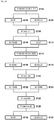
- the figure 7 is a summary flowchart of the steps of a method for controlling a set E of batteries in accordance with an embodiment of the invention, similar to the mode described with reference to figure 6 , in which the set E of batteries comprises a number n of batteries, where n is an integer greater than or equal to 2.
- control device DP monitors the activity state of the power source GE.
- the control device DP controls, during two simultaneous steps E804 and E806, the recharging of a battery Bi of the assembly E up to a determined level of charge NR MIN considered to be high and the resting of the other batteries of the set E, i being an integer between 1 and n and initialized to a determined value. In the mode described with reference to the figure 6 , i is initialized to the value 2.
- control device DP receives information MESi indicating that the charge level of the battery Bi has reached the level NR MIN considered to be high. Thus, the control device DP controls the stopping of the source GE during a step E810.
- the control device DP modifies during a step E812 the whole number i to change at each battery iteration relating to the recharging step (E804) and thus the batteries relating to standby (E806). If the integer i is equal to the number of batteries n, then i is reset to 1, otherwise i is incremented by one.
- control device DP controls, during two simultaneous steps E816 and E818, the discharge of the battery Bi of the assembly E up to a determined charge level ND MIN considered weak and the rest of the other batteries in set E.
- the control device DP receives information MESi indicating that the charge level of the battery Bi has reached the level ND MIN considered to be low. Thus, the control device DP controls the starting of the source GE during a step E822.
- the control device DP modifies during a step E812 the whole number i to change the battery to be discharged (E816) and the batteries to be put to rest (E818) . If the integer i is equal to the number of batteries n, then i is reset to 1, otherwise i is incremented by one.
- the figure 8 is a timing diagram representing the different stages of a control method in accordance with an embodiment of the invention, which differs from the mode described with reference to figures 6 and 7 in that the nominal capacity of each of the batteries B2 and B3 is equal to half that of the battery B1.
- the batteries B2 and B3 are recharged, discharged and put to rest simultaneously.
- the C4 cyclic sequence described with reference to figure 6 is applied to each of the batteries B1, B2 and B3.
- the sequence C4 is applied alternately between the battery B1 on the one hand, and simultaneously the batteries B2 and B3 on the other hand.
- the figure 9 is a timing diagram representing the different stages of a control method in accordance with an embodiment of the invention, in which the set of batteries E comprises 4 batteries B1 to B4 all having the same nominal capacity.
- the control device DP controls the resting of the battery B1 after each recharge and after each discharge of this battery B1.
- the other batteries in set E have simultaneous recharging and discharging cycles, without being put to rest.
- Charging of battery B1 is simultaneous with recharging of other batteries to increase the efficiency of the GE source.
- the discharge of the battery B1 is also simultaneous with the discharge of the other batteries.
- the figure 10 is a timing diagram representing the different stages of a control method in accordance with another embodiment of the invention in which the battery set E also includes 4 batteries B1 to B4 all having the same nominal capacity.
- This mode differs from the mode described with reference to the figure 9 in that the control device DP controls the resting of each of two batteries B1 and B4 of the assembly E after each recharge and each discharge of the battery in question.
- a cyclic sequence C5 comprising a discharge followed by a quiescent and a recharge followed by another quiescent is applied alternately between the batteries B1 and B4.
- the mode illustrated by figure 10 makes it possible to extend the life of the battery B4, in addition to that of the battery B1, while maintaining an acceptable efficiency of the GE source despite the reduction in charge (3 batteries at the same time).
- the figure 11 illustrates an architecture of a control system for a set E of batteries B1 and B2, in accordance with an embodiment of the invention.
- This system comprises two power sources: an unreliable electrical network N_ELEC and a generator GE, the control device DP according to the invention and a consumer device HOSP.
- the HOSP consumer device is an electronic medical device, requiring permanent availability of an electric current.
- the system presented to the figure 11 is located in a rural area without a reliable electricity network.
- control device DP controls a set of two batteries B1 and B2, as well as the source GE, but does not control the state of activity of the source N_ELEC.
- each of the batteries B1 and B2 comprises an electronic management entity, associated with the battery for its management, and called BMS (for "Battery Management System” in English).
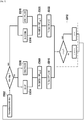
- the figure 12 is a flowchart representing steps of a method for controlling a set E of two batteries B1 and B2 in accordance with an embodiment of the invention. The method is implemented by the DP control device according to the invention and included in the control system described with reference to the figure 11 .
- the control device DP obtains info-disp information representative of the state of activity of the electrical network N_ELEC. This information indicates that the source N_ELEC is in active state.
- the info-disp information on the activity status of the N_ELEC source is received from an alarm device.
- this info-disp information is monitored by the control device DP periodically permanently, for example every 2 seconds.
- the DP device controls the recharging of the batteries B1 and B2.
- the HOSP consumer device is supplied directly by the N_ELEC source.
- the device DP controls the recharging of the battery B1 up to a determined charge level, of 100% for example. Simultaneously, during a step E106, the device DP puts the battery B2 at rest.
- control device DP receives information mes1 representative of the charge level of the battery B1, indicating that the charge level of the battery B1 is 100%. The DP device then begins to recharge the second battery B2.
- control device DP controls the resting of the battery B1 and the recharging of the battery B2 up to a determined charge level, for example of 100%.
- the control device DP obtains the info-disp information indicating that the state of the source N_ELEC has become inactive, even before that the charge level of battery B2 has reached the determined level of 100%.
- the control device DP controls the discharge of the battery B1 during a step E116 up to a determined charge level, of 0% for example, and puts at rest the battery B2 during a step E118 simultaneous with step E116.
- the DP device selects the discharge of the last battery to be put to rest, namely battery B1.
- control device DP receives information mes1 indicating that the level of charge of the battery B1 has reached the level of 0%.
- the control device DP then controls the supply of the consumer device HOSP by the battery B2. During two simultaneous steps E122 and E124, the control device DP controls the resting of the battery B1 and the discharge of the battery B2 up to a determined charge level, for example of 0%.
- control device DP receives information mes2 indicating that the level of charge of the battery B2 has reached the level of 0%.
- control device DP controls, during a step E128 the starting of the generator generator GE to supply the consumer device HOSP and recharge batteries B1 and B2 in an alternative way.
- the power source is an unreliable N_ELEC electrical network, which may have several interruptions or provide an electrical current or voltage with an unstable value.
- the power source is a SOL generator of electrical energy from solar energy.
- the power source is a WND generator of electrical energy from wind energy.
- control system includes several power sources, of the same type or of different types.
- control system comprises at least two power sources, one of which is a Stirling type generator.
- This type of generator can cover the power of use, that is to say power the BTS consumer device, but not the recharging of the batteries.
- the consumer device can be a device other than a BTS base station or an HOSP medical device.
- the consumer device is an electronic device which requires to be supplied electrically with a minimum threshold of availability and / or a minimum threshold of stability at the level of the current intensity, the voltage or the electric power which supplies it.
- control system includes several consumer devices.
- At least one of the batteries B1 and B2 controlled by the control device is of the Lead, or Nickel type or a hot battery.
- the batteries B1 and B2 of the set E of batteries are not necessarily of the same technology.
- the data mes1, mes2, mes3 representative of the charge levels of the batteries of the set E are based on current or voltage measurements at the level of the batteries.
- the data mes1, mes2, mes3 representative of the charge levels of the batteries of the set E are based on estimates, using for example machine learning algorithms.
- the data mes1, mes2, mes3 representative of the battery charge levels are based on TIMER countdown counters. For example, it can be estimated that battery B1, whose charge level is presented to the figure 4 , discharges after 5 and a half hours, and charges in 1 and a half hours.
- the figure 13 presents a functional architecture of a DP device, according to the invention, as well as two power sources of different types: a first source of the GE generator type, and a second source of the SOL solar panel type, WND wind turbine or a electrical network N_ELEC.
- the DP control device controls a set of two batteries B1 and B2 which can each be connected to a power source and to a consumer device.
- the SURV monitoring module is configured to monitor info-disp information each representative of an activity state of a GE, SOL, WND or N_ELEC power source. This information can be obtained by receiving a message from the source in question or by reading from a memory.
- this info-disp information is transmitted from the CONT control module to the SURV monitoring module.
- connection means K1, K'1 relating to a battery B1 are configured to provide an electrical connection between the battery B1 and a power source N-ELEC, GE, SOL or WND to recharge the battery, or provide an electrical connection between the battery B1 and a consumer device to discharge the battery, or electrically disconnect the battery B1 from any power source and from any consumer device, to put the battery at rest.
- the discharge circuit CD allows the passage of an electric current for discharging the battery B1
- the circuit comprising the means K'1 called CR charging circuit
- the discharge can be optimized by closing K'1 to avoid Joule losses in the diode.
- connection means K1, K'1, K2 and K'2 are power switches. These switches can be electromechanical such as a relay or electronic such as an MOS transistor.
- the diode functions D1 and D2 can be passive diodes or controlled switches, for example a transistor controlled by an electronic circuit performing the same function as a passive diode.
- the diode D1 (respectively D2) allows the instantaneous discharge of the battery B1 (respectively B2) and therefore to obtain an uninterrupted power supply when the N-ELEC power sources, GE, SOL or WND no longer provide current.
- Closing the switch K'1 makes it possible to recharge the battery B1 (respectively B2), but also during the discharge phases to eliminate by bypass the Joules losses and the voltage drop in the diode function D1 (respectively D2) due to the threshold voltage of the diode function D1 (respectively D2).
- the opening of the torque K1 and K1 '(respectively K2 and K2') allows the battery B1 (respectively B2) to be put to rest and to stop any discharge below a critical voltage threshold for electrochemistry below which there is a risk of irreversibility of the reactions in the elements, in particular by dendrite metallization and internal short circuit with heating and starting of an uncontrollable oxidation or combustion reaction.
- the recharging and discharging commands are such that the consumer device BTS, HOSP, is supplied without interruption either by the power source N-ELEC, GE, SOL, or WND, or by the discharge of a said battery, B1 or B2.
- the DC coupling module commands to close the contactors K1 and K'1 and to open K2 and K'2.
- the battery B1 discharges via the circuit comprising the switch K'1 without loss in the diode D1. Battery B2 is put to rest.
- the battery B1 is discharged, the DC coupling module commands to open K'1, then the CONT control module commands to start the GE source.
- the DC coupling module commands to close K'2 there is not a current flowing between the batteries B1 and B2 because the switch K'1 is open. Then, the DC coupling module commands to open K1, then to close K2. In this way, the battery B2 is charging and the battery B1 is put to rest.
- the DC coupling module commands to open K'2, close K'1, then open K2.
- the DC coupling module commands to open K'1 then to close K'2 and K2.
- connection means K1, K'1, K2, K'2, D1 and D2 are included in the control device DP.
- these means are included in another device or another box than the DP control device, but are controlled by the DC coupling module of the DP control device.
- the charging and discharging circuits of a battery can be controlled independently of each other.
- the independence of the charge and discharge circuits makes it possible to introduce a certain redundancy.
- the discharge of the battery B1 can occur either by closing the switch K1, or by closing the switch K'1.
- the CONT control module is configured to control the activity state of a power source, for example of the GE generator type.
- the COM communication module is configured to obtain at least one piece of information mes1 (resp. Mes 2) representative of a charge level of a battery B1 (resp. B2), to determine, as a function of this information mes1 (or mes2 ), which battery among B1 and B2 to recharge or discharge.
- the level of charge SoC (for “State of Charge” in English) of a battery can be expressed in percentage by the ratio between the available charge Q in the battery and the maximum capacity Cmax of this battery.
- the charge Q and the charge level SoC can be determined from the battery voltage if it reflects the state of charge.
- the voltage is high at the end of the charge, for example greater than 3.45 V x k for Lithium Iron Phosphate (LFP) batteries, k being the number of elements in series to constitute the battery.
- LFP Lithium Iron Phosphate
- the voltage is low at the end of discharge, for example less than 3 V x k for these types of batteries.
- the voltage is not a sufficiently precise indicator for the intermediate states of charge and this measurement can be supplemented by a counter accumulating the charge Q at a given instant, this charge Q being assumed to be contained in the battery and bounded between 0 and the maximum capacity value Cmax.
- the calculation of the charge Q uses at least current and time measurements, or even other measurements such as temperature and other information stored as manufacturer's reference data or historical data acquired during the use of the battery. .
- the state of health is affected by the age of the battery, also called calendar aging, cycle history, temperature, time spent at different depths of discharge, charging current, any abuse suffered (overcharging, under-discharge, short circuit), poor maintenance, etc.
- the maximum value is corrected, for example as a function of the nominal capacity of the battery, or as a function of the state of health, or of the temperature.
- the measurements of the charge levels of a battery can be acquired beforehand by a BMS entity associated with this battery.
- the information mes1 or mes2 is recovered via a communication link, for example a link of analog, modbus, CAN, FIP, Ethernet or another type.
- At least one B1 battery is made of Lithium.
- the two parallel circuits, for recharging and discharging, comprising the means K1, K'1 and D1 relating to this battery B1 are included in the electronic management entity BMS associated with the battery B1.
- the DP control device has the architecture of a computer, as illustrated in the figure 14 . It notably includes a processor 7, a random access memory 8, a read-only memory 9, a non-volatile flash memory 10 in a particular embodiment of the invention, as well as communication means 11. Such means are known per se and are not described in more detail here.
- the read-only memory 9 of the control device DP according to the invention constitutes a recording medium in accordance with the invention, readable by the processor 7 and on which a computer program Prog according to the invention is recorded.
- the memory 10 of the control device DP makes it possible to record variables used for the execution of the steps of the invention, such as the data mesl, mes2, mes3 representative of the charge levels of the batteries, the info-disp information representative of the power source activity states, a value from a TIMER countdown timer used to estimate a battery charge level.
- the Prog computer program defines functional and software modules, configured to drive batteries. These functional modules rely on and / or control the hardware elements 7-11 of the DP control device mentioned above.
Landscapes
- Engineering & Computer Science (AREA)
- Power Engineering (AREA)
- Charge And Discharge Circuits For Batteries Or The Like (AREA)
- Secondary Cells (AREA)
Applications Claiming Priority (1)
| Application Number | Priority Date | Filing Date | Title |
|---|---|---|---|
| FR1873524A FR3091055A1 (fr) | 2018-12-20 | 2018-12-20 | Procédé et dispositif de commande de recharge et de décharge de batteries d’un ensemble desdites batteries. |
Publications (1)
| Publication Number | Publication Date |
|---|---|
| EP3672024A1 true EP3672024A1 (de) | 2020-06-24 |
Family
ID=66776470
Family Applications (1)
| Application Number | Title | Priority Date | Filing Date |
|---|---|---|---|
| EP19217597.4A Pending EP3672024A1 (de) | 2018-12-20 | 2019-12-18 | Vorrichtung und verfahren zum steuern der aufladung und entladung von batterien einer gruppe solcher batterien |
Country Status (3)
| Country | Link |
|---|---|
| US (1) | US20200203962A1 (de) |
| EP (1) | EP3672024A1 (de) |
| FR (1) | FR3091055A1 (de) |
Families Citing this family (2)
| Publication number | Priority date | Publication date | Assignee | Title |
|---|---|---|---|---|
| US20230114110A1 (en) * | 2021-10-08 | 2023-04-13 | Advanced Powering Services, Inc. | Standby Solution For Extended Run Time Power Systems |
| US20230202336A1 (en) * | 2021-12-28 | 2023-06-29 | Toyota Motor North America, Inc. | Power allocation based on energy source |
Citations (4)
| Publication number | Priority date | Publication date | Assignee | Title |
|---|---|---|---|---|
| US20120235624A1 (en) * | 2011-03-16 | 2012-09-20 | Johnson Controls Technology Company | Systems and methods for controlling multiple storage devices |
| US20130221896A1 (en) * | 2012-02-29 | 2013-08-29 | Huawei Technologies Co., Ltd. | Power supply method, power supply device, and base station |
| US20170285109A1 (en) * | 2016-03-30 | 2017-10-05 | Honda Motor Co.,Ltd. | Power supply apparatus, transport device including power supply apparatus, estimating method of estimating correlation information between charge rate and open-end voltage of electric storage section, and computer readable medium for estimating correlation information |
| US20180248376A1 (en) * | 2015-10-28 | 2018-08-30 | Panasonic Intellectual Property Management Co., Ltd. | Power conversion system and control device |
-
2018
- 2018-12-20 FR FR1873524A patent/FR3091055A1/fr not_active Withdrawn
-
2019
- 2019-12-18 EP EP19217597.4A patent/EP3672024A1/de active Pending
- 2019-12-20 US US16/723,025 patent/US20200203962A1/en not_active Abandoned
Patent Citations (4)
| Publication number | Priority date | Publication date | Assignee | Title |
|---|---|---|---|---|
| US20120235624A1 (en) * | 2011-03-16 | 2012-09-20 | Johnson Controls Technology Company | Systems and methods for controlling multiple storage devices |
| US20130221896A1 (en) * | 2012-02-29 | 2013-08-29 | Huawei Technologies Co., Ltd. | Power supply method, power supply device, and base station |
| US20180248376A1 (en) * | 2015-10-28 | 2018-08-30 | Panasonic Intellectual Property Management Co., Ltd. | Power conversion system and control device |
| US20170285109A1 (en) * | 2016-03-30 | 2017-10-05 | Honda Motor Co.,Ltd. | Power supply apparatus, transport device including power supply apparatus, estimating method of estimating correlation information between charge rate and open-end voltage of electric storage section, and computer readable medium for estimating correlation information |
Also Published As
| Publication number | Publication date |
|---|---|
| FR3091055A1 (fr) | 2020-06-26 |
| US20200203962A1 (en) | 2020-06-25 |
Similar Documents
| Publication | Publication Date | Title |
|---|---|---|
| EP3672019B1 (de) | Steuerverfahren und -vorrichtung des auf- und entladens von batterien einer anordnung solcher batterien mit teilweiser aufladung einer batterie | |
| WO2006003287A1 (fr) | Procédé de gestion d'un parc de batteries rechargeables | |
| EP0498715B1 (de) | Verfahren zur Ladungsoptimierung einer Akkumulatorenbatterie und Vorrichtung zu dessen Durchführung | |
| EP2079125B1 (de) | Verfahren zur Steuerung des Aufladevorgangs einer Batterie | |
| FR3122951A1 (fr) | Procédé et système de contrôle de la recharge d’une flotte de véhicules automobiles électriques | |
| WO2016087781A1 (fr) | Procédé pour la gestion d'énergie | |
| EP2346711A2 (de) | Verfahren und vorrichtung zur steuerung eines in einem kraftfahrzeug anbringbaren mikrohybridsystems mit bremsenergierückspeisung | |
| EP3672024A1 (de) | Vorrichtung und verfahren zum steuern der aufladung und entladung von batterien einer gruppe solcher batterien | |
| WO2000002300A1 (fr) | Procede de commande d'une centrale electrique associee a une source d'energie temporellement aleatoire | |
| FR3067878B1 (fr) | Procede de charge de batteries pour un aeronef et systeme de stockage d'energie electrique | |
| EP2395594B1 (de) | Vorrichtung und Verfahren zur Stromversorgung eines mobilen Kommunikationssystems und eine Sensoranordnung, die eine derartige Vorrichtung aufweist. | |
| FR2879852A1 (fr) | Procede et systeme d'alimentation electrique autonome par energie renouvelable | |
| FR2964265A1 (fr) | Procede de charge d'une batterie electrique | |
| EP3189577B1 (de) | Verbesserte verwaltung einer stromerzeugungsanlage | |
| FR3033674A1 (fr) | Carte electronique de pilotage energetique d'un equipement electrique autonome et communicant | |
| FR3010250A1 (fr) | Systeme de gestion electrique des blocs d'une batterie en fonction de la puissance requise de la batterie et de la charge des blocs | |
| EP4175160B1 (de) | Optimierung der verwendung einer elektrogengruppe | |
| FR3099647A1 (fr) | Système d'alimentation électrique à modules Li/MnO2 | |
| FR2849298A1 (fr) | Dispositif de controle de l'etat de charge, a tension constante, d'un ensemble de batterie a generateurs electrochimiques secondaires | |
| FR3067185A1 (fr) | Dispositif de commande de generation d'energie | |
| FR3110036A1 (fr) | Procédé de commande d'un système de stockage d'énergie comprenant au moins deux dispositifs élémentaires de stockage d'énergie, dispositif de commande associé et système de stockage d'énergie comportant un tel dispositif de commande | |
| FR3112868A1 (fr) | Ensemble comportant un automate programmable, une alimentation externe et une source d’alimentation principale | |
| EP4674024A1 (de) | Gepulstes schnellaufladeverfahren mit spannungsinkrementen mit geregelter amplitude | |
| FR3116960A1 (fr) | Procédé de régulation d’un réseau de distribution électrique basse tension | |
| WO2006059016A1 (fr) | Module de gestion de la charge et de la decharge d’un dispositif de stockage |
Legal Events
| Date | Code | Title | Description |
|---|---|---|---|
| PUAI | Public reference made under article 153(3) epc to a published international application that has entered the european phase |
Free format text: ORIGINAL CODE: 0009012 |
|
| STAA | Information on the status of an ep patent application or granted ep patent |
Free format text: STATUS: THE APPLICATION HAS BEEN PUBLISHED |
|
| AK | Designated contracting states |
Kind code of ref document: A1 Designated state(s): AL AT BE BG CH CY CZ DE DK EE ES FI FR GB GR HR HU IE IS IT LI LT LU LV MC MK MT NL NO PL PT RO RS SE SI SK SM TR |
|
| AX | Request for extension of the european patent |
Extension state: BA ME |
|
| RAP1 | Party data changed (applicant data changed or rights of an application transferred) |
Owner name: ORANGE |
|
| STAA | Information on the status of an ep patent application or granted ep patent |
Free format text: STATUS: REQUEST FOR EXAMINATION WAS MADE |
|
| 17P | Request for examination filed |
Effective date: 20200630 |
|
| RBV | Designated contracting states (corrected) |
Designated state(s): AL AT BE BG CH CY CZ DE DK EE ES FI FR GB GR HR HU IE IS IT LI LT LU LV MC MK MT NL NO PL PT RO RS SE SI SK SM TR |
|
| STAA | Information on the status of an ep patent application or granted ep patent |
Free format text: STATUS: EXAMINATION IS IN PROGRESS |
|
| 17Q | First examination report despatched |
Effective date: 20210401 |
|
| RAP3 | Party data changed (applicant data changed or rights of an application transferred) |
Owner name: ORANGE |
|
| GRAP | Despatch of communication of intention to grant a patent |
Free format text: ORIGINAL CODE: EPIDOSNIGR1 |
|
| STAA | Information on the status of an ep patent application or granted ep patent |
Free format text: STATUS: GRANT OF PATENT IS INTENDED |
|
| INTG | Intention to grant announced |
Effective date: 20250331 |
|
| GRAJ | Information related to disapproval of communication of intention to grant by the applicant or resumption of examination proceedings by the epo deleted |
Free format text: ORIGINAL CODE: EPIDOSDIGR1 |
|
| STAA | Information on the status of an ep patent application or granted ep patent |
Free format text: STATUS: EXAMINATION IS IN PROGRESS |
|
| INTC | Intention to grant announced (deleted) |