EP3675572B1 - Drahtloskommunikationsverfahren, netzwerkvorrichtung und endgerätevorrichtung - Google Patents
Drahtloskommunikationsverfahren, netzwerkvorrichtung und endgerätevorrichtung Download PDFInfo
- Publication number
- EP3675572B1 EP3675572B1 EP17924071.8A EP17924071A EP3675572B1 EP 3675572 B1 EP3675572 B1 EP 3675572B1 EP 17924071 A EP17924071 A EP 17924071A EP 3675572 B1 EP3675572 B1 EP 3675572B1
- Authority
- EP
- European Patent Office
- Prior art keywords
- random access
- access response
- response
- rnti
- access request
- Prior art date
- Legal status (The legal status is an assumption and is not a legal conclusion. Google has not performed a legal analysis and makes no representation as to the accuracy of the status listed.)
- Active
Links
Images


Classifications
-
- H—ELECTRICITY
- H04—ELECTRIC COMMUNICATION TECHNIQUE
- H04W—WIRELESS COMMUNICATION NETWORKS
- H04W74/00—Wireless channel access
- H04W74/08—Non-scheduled access, e.g. ALOHA
- H04W74/0833—Random access procedures, e.g. with 4-step access
-
- H—ELECTRICITY
- H04—ELECTRIC COMMUNICATION TECHNIQUE
- H04L—TRANSMISSION OF DIGITAL INFORMATION, e.g. TELEGRAPHIC COMMUNICATION
- H04L5/00—Arrangements affording multiple use of the transmission path
- H04L5/0001—Arrangements for dividing the transmission path
- H04L5/0003—Two-dimensional division
- H04L5/0005—Time-frequency
- H04L5/0007—Time-frequency the frequencies being orthogonal, e.g. OFDM(A) or DMT
- H04L5/001—Time-frequency the frequencies being orthogonal, e.g. OFDM(A) or DMT the frequencies being arranged in component carriers
-
- H—ELECTRICITY
- H04—ELECTRIC COMMUNICATION TECHNIQUE
- H04W—WIRELESS COMMUNICATION NETWORKS
- H04W72/00—Local resource management
- H04W72/04—Wireless resource allocation
- H04W72/044—Wireless resource allocation based on the type of the allocated resource
- H04W72/0453—Resources in frequency domain, e.g. a carrier in FDMA
-
- H—ELECTRICITY
- H04—ELECTRIC COMMUNICATION TECHNIQUE
- H04W—WIRELESS COMMUNICATION NETWORKS
- H04W72/00—Local resource management
- H04W72/20—Control channels or signalling for resource management
-
- H—ELECTRICITY
- H04—ELECTRIC COMMUNICATION TECHNIQUE
- H04W—WIRELESS COMMUNICATION NETWORKS
- H04W72/00—Local resource management
- H04W72/20—Control channels or signalling for resource management
- H04W72/21—Control channels or signalling for resource management in the uplink direction of a wireless link, i.e. towards the network
-
- H—ELECTRICITY
- H04—ELECTRIC COMMUNICATION TECHNIQUE
- H04W—WIRELESS COMMUNICATION NETWORKS
- H04W72/00—Local resource management
- H04W72/20—Control channels or signalling for resource management
- H04W72/23—Control channels or signalling for resource management in the downlink direction of a wireless link, i.e. towards a terminal
-
- H—ELECTRICITY
- H04—ELECTRIC COMMUNICATION TECHNIQUE
- H04W—WIRELESS COMMUNICATION NETWORKS
- H04W74/00—Wireless channel access
- H04W74/002—Transmission of channel access control information
-
- H—ELECTRICITY
- H04—ELECTRIC COMMUNICATION TECHNIQUE
- H04W—WIRELESS COMMUNICATION NETWORKS
- H04W74/00—Wireless channel access
- H04W74/002—Transmission of channel access control information
- H04W74/004—Transmission of channel access control information in the uplink, i.e. towards network
Definitions
- This invention relates to the communications field, and more specifically, to wireless communication methods, a terminal device and a network device,
- LTE Long Term Evolution
- a terminal device and a network may perform uplink and downlink communication by using the fixed uplink carrier and downlink carrier respectively.
- the terminal may perform random access by using the fixed uplink carrier.
- a future communications system requires relatively high communication performance.
- Embodiments of this application provide a wireless communication method and a device, to improve communication performance in terms of random access.
- the technical solutions according to the embodiments of this application may be applied to a variety of communications systems, such as a Global System for Mobile communications (Global System for Mobile Communications, "GSM” for short) system, a Code Division Multiple Access (Code Division Multiple Access, “CDMA” for short) system, a Wideband Code Division Multiple Access (Wideband Code Division Multiple Access, “WCDMA” for short) system, a General Packet Radio Service (General Packet Radio Service, "GPRS” for short), a Long Term Evolution (Long Term Evolution, “LTE” for short) system, an LTE Frequency Division Duplex (Frequency Division Duplex, "FDD” for short) system, an LTE Time Division Duplex (Time Division Duplex, "TDD” for short), a Universal Mobile Telecommunications system (Universal Mobile Telecommunications system, "UMTS” for short), a Worldwide Interoperability for Microwave Access (Worldwide Interoperability for Microwave Access, "WiMAX” for short) communications system, a future 5G system (which
- system and “network” in this specification are usually interchangeably used in this specification.
- the term “and/or” in this specification is only an association relationship for describing the associated objects, and represents that three relationships may exist.
- a and/or B may represent the following three cases: only A exists, both A and B exist, and only B exists.
- the character "/" in this specification generally indicates an "or" relationship between the associated objects.
- FIG. 1 shows a wireless communications system 100 according to an embodiment of this application.
- FIG. 1 exemplarily shows one network device and two terminal devices.
- the wireless communications system 100 may include a plurality of network devices and another quantity of terminal devices may be included in a coverage area of each network device. This is not limited in this embodiment of this application.
- the wireless communications system 100 may further include another network entity such as a network controller or a mobility management entity. This is not limited in this embodiment of this application.
- the wireless communications system 100 may include a network device 110.
- the network device 110 may be a device communicating with a terminal device.
- the network device 110 may provide communication coverage for a specific geographic area, and may communicate with a terminal device (for example, UE) located within the coverage area.
- a terminal device for example, UE
- the network device 110 may be a base transceiver station (Base Transceiver Station, BTS) in a GSM system or a CDMA system, may be a NodeB (NodeB, NB) in a WCDMA system, or may be an evolved Node B (Evolved Node B, eNB or eNodeB) in an LTE system or a wireless controller in a cloud radio access network (Cloud Radio Access Network, CRAN), or the network device may be a relay station, an access point, an in-vehicle device, a wearable device, a network-side device in a future 5G network, a network device in a future evolved public land mobile network (Public Land Mobile Network, PLMN), or the like.
- BTS Base Transceiver Station
- NB NodeB
- eNB evolved Node B
- CRAN Cloud Radio Access Network
- the network device may be a relay station, an access point, an in-vehicle device, a wearable device, a network
- the wireless communications system 100 further includes at least one terminal device 120 located within a coverage area of the network device 110.
- the terminal device 120 may be mobile or fixed.
- the terminal device 120 may be an access terminal, user equipment (User Equipment, UE), a user unit, a user station, a mobile site, a mobile station, a remote station, a remote terminal, a mobile device, a user terminal, a terminal, a wireless communications device, a user agent, or a user apparatus.
- User Equipment User Equipment
- the access terminal may be a cellular phone, a cordless phone, a Session Initiation Protocol (Session Initiation Protocol, SIP) phone, a wireless local loop (Wireless Local Loop, WLL) station, a personal digital assistant (Personal Digital Assistant, PDA), a handheld device having a wireless communication function, a computing device or another processing device connected to a wireless modem, an in-vehicle device, a wearable device, a terminal device in a future 5G network, a terminal device in a future evolved PLMN, or the like.
- Session Initiation Protocol Session Initiation Protocol, SIP
- WLL Wireless Local Loop
- PDA Personal Digital Assistant
- the terminal device 120 may perform device to device (Device to Device, D2D) communication.
- D2D Device to Device
- a 5G system or network may be further referred to as a new radio (New Radio, NR) system or network.
- New Radio NR
- a high frequency band is an important alternative frequency band for deploying a 5G (NR) network. Because a frequency band is relatively high, a coverage area is relatively limited (as compared with low frequency LTE).
- a downlink Downlink
- MIMO Multiple Input Multiple Output
- MIMO hybrid Beamforming
- one uplink (Uplink, UL) carrier may be deployed at a low frequency and used to perform NR transmission.
- the UL carrier may be referred to as a supplementary uplink (Supplementary Uplink, SUL) carrier.
- NR has at least two UL carriers.
- one UL carrier is the SUL carrier, and the other UL carrier is a high frequency UL carrier (which may be referred to as an NR dedicated UL (dedicated UL) carrier).
- the NR system may include a high frequency UL carrier that belongs to a frequency band f0 and a low frequency UL carrier that belongs to a frequency band f1.
- frequency division multiplexing Frequency Division Duplexing, FDD
- time division multiplexing Time Division Duplexing, TDD
- TDD Time Division Duplexing
- the SUL carrier may further share a spectrum resource with the LTE system.
- a spectrum resource with the LTE system.
- FDM Frequency Division Multiplexing
- TDM Time Division Multiplexing
- the NR system may alternatively have three or more UL carriers.
- a plurality of UL carriers included in the NR system may all be used by the terminal device to perform uplink transmission. However, during configuration, it may be only configured that the terminal device uses one or more UL carriers to perform uplink transmission.
- a quantity of UL carriers used by the terminal device and a specific UL carrier that are configured by the network device may change dynamically.
- the terminal device monitors (monitor) a random access request (Random Access Request, RAR) of the network device at a corresponding position.
- the network device uses a random access radio network temporary identity (Random Access Radio Network Temporary Identity, RA-RNTI) to send a random access response.
- RA-RNTI Random Access Radio Network Temporary Identity
- the terminal device uses a same RA-RNTI to receive the random access response.
- the RA-RNTI may be calculated in the following three manners.
- RA-RNTI 1 + t_id + 10 * f_id
- t_id is an index of the first subframe in a specified PRACH resource
- f id is an index of a specified PRACH of the subframe in ascending order in frequency domain.
- RA-RNTI 1 + t_id + 10 * f_id + 60 * SFN_id mod Wmax / 10
- t_id is an index of the first subframe in a specified PRACH resource
- f id is an index of a specified PRACH of the subframe in ascending order in frequency domain
- SFN_id is an index of the first radio frame of the specified PRACH resource
- Wmax is 400.
- RA-RNTI 1 + floor SFN_id / 4 where SFN_id is an index of the first radio frame of the specified PRACH resource.
- a manner of acquiring an RA-RNTI in the NR system may be the same as or different from a manner of acquiring an RA-RNTI in the LTE system.
- the two terminal devices may receive the same RAR, and a UL carrier on which a preamble that corresponds to the RAR is sent cannot be distinguished.
- the embodiments of this application provide the following solutions for random access.
- FIG. 6 is a schematic flowchart of a wireless communication method 200 according to an embodiment of this application.
- the method 200 may be optionally applied to the system shown in FIG. 1 , but is not limited thereto.
- the method 200 includes at least some of the following content.
- a terminal device sends a first random access request to a network device on a first uplink carrier.
- the network device receives the first random access request sent by the terminal device on the first uplink carrier.
- the network device sends a first random access response in response to the first random access request based on the first uplink carrier.
- the terminal device acquires, based on the first uplink carrier, the first random access response sent by the network device in response to the first random access request.
- a random access response is fed back based on an uplink carrier on which a random access request is sent, so that if there is a plurality of uplink carriers, a source of the random access request corresponding to the random access response can be distinguished when possible.
- the network device determines a first random access radio network temporary identity RA-RNTI required to send the first random access response; and sends the first random access response based on the determined first RA-RNTI.
- the terminal device determines the first RA-RNTI for the first random access response; and acquires the first random access response based on the determined first RA-RNTI.
- the network device further determines at least one of the following based on the first uplink carrier: a resource required to send the first random access response, and information for indicating a random access request source in the first random access response; and sends the first random access response based on the determined at least one.
- the terminal device determines at least one of the following: the resource occupied by the first random access response, and the information for indicating the random access request source in the first random access response; and acquires the first random access response based on the determined at least one.
- the network device sends configuration information to the terminal device, where the configuration information is used to indicate at least one of the resource required to send the first random access response, a determining manner or one or more parameters of the first random access radio network temporary identity required to send the first random access response, and the information (that is, information that indicates a random access request source) carried in the first random access response.
- the resource required to send the first random access response, the determining manner or one or more parameters of the first random access radio network temporary identity required to send the first random access response, and the information carried in the first random access response may alternatively be preset on the terminal device and do not need to be configured by the network device.
- the resource that is determined based on the first uplink carrier and is required to send the first random access response includes: a control resource set CORESET or search space to which a control channel carrying the first random access response belongs.
- control resource set Control Resource Set, CORESET
- search space Search space
- the control channel carrying the first random access response belongs is different from a CORESET or search space to which a control channel carrying a second random access response belongs
- the second random access response is a response to a second random access request on a second uplink carrier.
- a physical random access channel Physical Random Access Channel
- PRACH Physical Random Access Channel
- RAR Random Access Response
- a control channel NR-PDCCH
- the network device configures a control channel differently to enable detection of different control channels after preambles are sent on different ULs.
- a CORESET 1 or a CORESET group 1 (which includes a plurality of CORESETs) is a control channel resource used to receive an RAR corresponding to a preamble sent in an NR dedicated UL
- a CORESET 2 or a CORESET group 2 (which includes a plurality of CORESETs) includes a control channel resource used to receive an RAR corresponding to a preamble sent in an NR SUL.
- a search space 1 includes a control channel resource used to receive an RAR corresponding to a preamble sent in an NR dedicated UL
- a search space 2 includes a control channel resource used to receive an RAR corresponding to a preamble sent in an NR SUL.
- information carried in a random access request source field of the first random access response is different from information carried in a random access request source field of the second random access response, where the second random access response is the response to the second random access request on the second uplink carrier, and the random access request source field indicates an uplink carrier on which the random access request is located.
- the network device adds information to a random access response to indicate a UL to which a corresponding random access request belongs.
- the RAR indicates that the corresponding random access request belongs to an NR dedicated UL or a SUL.
- the first random access response carries a random access request source field
- the second random access response does not carry a random access request source field
- the second random access response is the response to the second random access request on the second uplink carrier
- the random access request source field indicates an uplink carrier on which the random access request is located is the first uplink carrier
- the network device adds information to a random access response to indicate a UL to which a corresponding random access request belongs.
- the RAR does not indicate a UL to which a corresponding random access request belongs, the random access request correspondingly belongs to a default UL (for example, an NR dedicated UL). If the RAR indicates a UL, the random access request belongs to the indicated UL (for example, a SUL).
- the first uplink carrier and the second uplink carrier described above belong to different frequency bands.
- the first uplink carrier is the SUL carrier described in FIG. 2 to FIG. 5
- the second uplink carrier is the dedicated UL carrier described in FIG. 2 to FIG. 5 .
- a calculation formula of the first RA-RNTI is different from a calculation formula of a second RA-RNTI, or one or more parameters in a calculation formula of the first RA-RNTI are different from one or more parameters in a calculation formula of a second RA-RNTI, where the second RA-RNTI is an RA-RNTI required for the second random access response to the second random access request on the second uplink carrier.
- a control channel (NR-PDCCH) first needs to be detected before a random access response can be received.
- Transmission on a control channel is scrambled by using an RA-RNTI.
- RA-RNTI Different RA-RNTIs may distinguish RARs corresponding to different preambles.
- SUL is supported for random access, compared with a dedicated UL carrier, an extra factor is introduced into a formula of an RA-RNTI. The factor is associated with the SUL. In this way, it can be avoided that preambles on two ULs correspond to a same RA-RNTI.
- the value range of an RA-RNTI is [x, y] (y > x ⁇ 0).
- a factor Z is added based on the foregoing technology to calculate an RA-RNTI, so that it can be avoided that two ULs correspond to a same RA-RNTI.
- the formula for calculating an RA-RNTI may be the foregoing Formula 1, Formula 2 or Formula 3, and Z may be added to Formula 1, Formula 2, and Formula 3 respectively to obtain formulas for calculation for a SUL carrier.
- Z may be not greater than y. In this case, instead of being completely avoided, a same RA-RNTI is less likely to occur.
- FIG. 7 is a schematic flowchart of a wireless communication method 300 according to an embodiment of this application not covered by the claimed invention.
- the method 300 includes at least some of the following content.
- a network device determines configuration information during random access for each of a plurality of uplink carriers.
- the plurality of uplink carriers belongs to different frequency bands respectively.
- the network device sends the configuration information for each uplink carrier to a terminal device.
- the terminal device receives the configuration information during random access configured by the network device for each of the plurality of uplink carriers.
- the network device configures the configuration information during random access for each of the plurality of uplink carriers for the terminal device, so that during random access, the terminal device can use the configuration information corresponding to each uplink carrier to perform random access.
- the configuration information includes a time domain resource and/or a frequency domain resource used to send a random access request on each uplink carrier, where RA-RNTIs corresponding to time domain resources and/or frequency domain resources used to send a random access request on different uplink carriers are at least partially different.
- the network device coordinates a time and frequency resource and/or a frequency domain resource of a RACH, thereby avoiding that RA-RNTIs corresponding to preambles on two UL carriers conflict or reduce a probability that RA-RNTIs corresponding to the preambles conflict.
- RACH Random Access Channel
- At least one of the following configuration information during random access determined respectively for different uplink carriers is different:
- the resource required to send the random access response includes: a control resource set CORESET or search space to which a control channel carrying the random access response belongs.
- control channels of random access responses corresponding to random access requests on different uplink carriers belong to different CORESETs or search spaces.
- RA-RNTIs for random access responses corresponding to random access requests on different uplink carriers have different calculation formulas or one or more different parameters in a calculation formula.
- the configuration information includes a configuration for the following: an indication of a random access request source in a random access response corresponding to a random access request transmitted on each uplink carrier.
- random access request source fields of random access responses corresponding to random access requests on different uplink carriers carry different information, where the random access request source field indicates an uplink carrier on which the random access request is located.
- the plurality of uplink carriers includes a first uplink carrier and a second uplink carrier, a first random access response carries a random access request source field, and a second random access response does not carry a random access request source field, where the first random access response is a response to a first random access request on the first uplink carrier, the second random access response is a response to a second random access request on the second uplink carrier, and the random access request source field indicates an uplink carrier on which the random access request is located is the first uplink carrier.
- FIG. 8 is a schematic block diagram of a network device 400 according to an embodiment of this application. As shown in FIG. 8 , the network device 400 includes a receiving unit 410 and a sending unit 420.
- the receiving unit 410 is configured to receive a first random access request sent by a terminal device on a first uplink carrier.
- the sending unit 420 is configured to send a first random access response in response to the first random access request based on the first uplink carrier.
- the network device 400 may perform corresponding operations performed by the network device in the foregoing method 200. For brevity, details are not described herein again.
- FIG. 9 is a schematic block diagram of a network device 500 according to an embodiment of this application not covered by the claimed invention.
- the network device 500 includes a processing unit 510 and a communications unit 520.
- the processing unit 510 is configured to determine configuration information during random access for each of a plurality of uplink carriers.
- the communications unit 520 is configured to send the configuration information for each uplink carrier to a terminal device.
- the network device 500 may perform corresponding operations performed by the network device in the foregoing method 300. For brevity, details are not described herein again.
- FIG. 10 is a schematic block diagram of a terminal device 600 according to an embodiment of this application. As shown in FIG. 10 , the terminal device 600 includes a sending unit 610 and a receiving unit 620.
- the sending unit 610 is configured to send a first random access request to a network device on a first uplink carrier.
- the receiving unit 620 is configured to acquire, based on the first uplink carrier, a first random access response sent by the network device in response to the first random access request.
- terminal device 600 may perform corresponding operations performed by the terminal device in the foregoing method 200. For brevity, details are not described herein again.
- FIG. 11 is a schematic block diagram of a terminal device 700 according to an embodiment of this application not covered by the claimed invention. As shown in FIG. 11 , the terminal device 700 includes a receiving unit 710 and an access unit 720.
- the receiving unit 710 is configured to receive configuration information during random access configured by a network device for each of a plurality of uplink carriers.
- the access unit 720 is configured to perform random access on at least one uplink carrier of the plurality of uplink carriers based on the configuration information.
- terminal device 700 may perform corresponding operations performed by the terminal device in the foregoing method 300. For brevity, details are not described herein again.
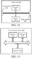
- FIG. 12 is a schematic structural diagram of a system chip 800 according to an embodiment of this application.
- the system chip 800 in FIG. 12 includes an input interface 801, an output interface 802, a processor 803, and a memory 804 that may be connected through an internal communication connection line, where the processor 803 is configured to execute code in the memory 804.
- the processor 803 when the code is executed, the processor 803 implements the method performed by a network device in the method embodiment. For brevity, details are not described herein again.
- the processor 803 when the code is executed, the processor 803 implements the method performed by a terminal device in the method embodiment. For brevity, details are not described herein again.
- FIG. 13 is a schematic block diagram of a communications device 900 according to an embodiment of this application.
- the communications device 900 includes a processor 910 and a memory 920.
- the memory 920 may store program code, and the processor 910 may execute the program code stored in the memory 920.
- the communications device 900 may include a transceiver 930, and the processor 910 may control the transceiver 930 to communicate externally.
- the processor 910 may invoke the program code stored in the memory 920 to perform corresponding operations of a network device in the method embodiment.
- the processor 910 may invoke the program code stored in the memory 920 to perform corresponding operations of a network device in the method embodiment.
- the processor 910 may invoke the program code stored in the memory 920 to perform corresponding operations of a terminal device in the method embodiment.
- the processor 910 may invoke the program code stored in the memory 920 to perform corresponding operations of a terminal device in the method embodiment.
- the processor in the embodiments of this application may be an integrated circuit chip and has a signal processing capability.
- the steps in the foregoing method embodiment may be implemented by using an integrated logic circuit of hardware in the processor or an instruction in the form of software.
- the processor may be a general-purpose processor, a digital signal processor (Digital Signal Processor, DSP), an application-specific integrated circuit (Application-Specific Integrated Circuit, ASIC), a field programmable gate array (Field Programmable Gate Array, FPGA) or another programmable logic device, a discrete gate or a transistor logic device, or a discrete hardware component.
- DSP Digital Signal Processor
- ASIC Application-Specific Integrated Circuit
- FPGA Field Programmable Gate Array
- the methods, steps, and logic block diagrams disclosed in the embodiments of this application may be implemented or performed.
- the general-purpose processor may be a microprocessor or the processor may alternatively be any conventional processor or the like.
- the steps in the methods disclosed with reference to the embodiments of this application may be directly performed or completed by a decoding processor embodied as hardware or performed or completed by using a combination of hardware and software modules in a decoding processor.
- the software module may be located at a random-access memory, a flash memory, a read-only memory, a programmable read-only memory or an electrically erasable programmable memory, a register or another mature storage medium in this field.
- the storage medium is located at a memory, and the processor reads information in the memory and completes the steps in the foregoing methods in combination with the hardware thereof.
- the memory in the embodiments of this application may be a volatile memory or a non-volatile memory, or may include both a volatile memory and a non-volatile memory.
- the non-volatile memory may be a read-only memory (Read-Only Memory, ROM), a programmable read-only memory (Programmable ROM, PROM), an erasable programmable read-only memory (Erasable PROM, EPROM), an electrically erasable programmable read-only memory (Electrically EPROM, EEPROM) or a flash memory.
- the volatile memory may be a random-access memory (Random-access memory, RAM) and is used as an external cache.
- RAMs can be used, for example, a static random-access memory (Static RAM, SRAM), a dynamic random-access memory (Dynamic RAM, DRAM), a synchronous dynamic random-access memory (Synchronous DRAM, SDRAM), a double data rate synchronous dynamic random-access memory (Double Data Rate SDRAM, DDR SDRAM), an enhanced synchronous dynamic random-access memory (Enhanced SDRAM, ESDRAM), a synchronous link dynamic random-access memory (Synchlink DRAM, SLDRAM), and a direct Rambus random-access memory (Direct Rambus RAM, DR RAM).
- static random-access memory Static RAM, SRAM
- DRAM dynamic random-access memory
- DRAM synchronous dynamic random-access memory
- SDRAM double data rate synchronous dynamic random-access memory
- Enhanced SDRAM, ESDRAM enhanced synchronous dynamic random-access memory
- Synchlink DRAM Synchrobus RAM
- Direct Rambus RAM Direct Rambus RAM
- the disclosed system, apparatus, and method may be implemented in other manners.
- the described apparatus embodiment is merely exemplary.
- the unit division is merely logical function division and may be other division in actual implementation.
- a plurality of units or components may be combined or integrated into another system, or some features may be ignored or not performed.
- the displayed or discussed mutual couplings or direct couplings or communication connections may be implemented through some interfaces.
- the indirect couplings or communication connections between the apparatuses or units may be implemented in electrical, mechanical or other forms.
- the units described as separate parts may or may not be physically separate, and parts displayed as units may or may not be physical units, may be located in one position, or may be distributed on a plurality of network units. Some or all of the units may be selected according to actual needs to achieve the objectives of the solutions of the embodiments.
- the functions When the functions are implemented in a form of a software functional unit and sold or used as an independent product, the functions may be stored in a computer-readable storage medium. Based on such an understanding, the technical solutions of this application essentially, or the part contributing to the prior art, or part of the technical solutions may be implemented in the form of a software product.
- the computer software product is stored in a storage medium, and includes several instructions for instructing a computer device (which may be a personal computer, a server, a network device, or the like) to perform all or some of the steps of the method described in the embodiments of this application.
- the foregoing storage medium includes: any medium that can store program code, such as a USB flash disk, a removable hard disk, a read-only memory ( Read-Only Memory, ROM), a random-access memory (Random-access memory, RAM), a magnetic disk, or an optical disk.
- program code such as a USB flash disk, a removable hard disk, a read-only memory ( Read-Only Memory, ROM), a random-access memory (Random-access memory, RAM), a magnetic disk, or an optical disk.
Landscapes
- Engineering & Computer Science (AREA)
- Signal Processing (AREA)
- Computer Networks & Wireless Communication (AREA)
- Mobile Radio Communication Systems (AREA)
Claims (15)
- Drahtloses Kommunikationsverfahren, umfassend:Senden, durch eine Endgerätvorrichtung, einer ersten Direktzugriffsanforderung an eine Netzwerkvorrichtung auf einem ersten Aufwärtsstreckenträger; undErfassen, durch die Endgerätvorrichtung, einer durch die Netzwerkvorrichtung als Reaktion auf die erste Direktzugriffsanforderung gesandten ersten Direktzugriffsantwort,wobei das Erfassen, durch die Endgerätvorrichtung, der durch die Netzwerkvorrichtung als Reaktion auf die erste Direktzugriffsanforderung gesandten ersten Direktzugriffsantwort umfasst:Erfassen der ersten Direktzugriffsantwort basierend auf einer ersten temporären Direktzugriff-Funknetzwerkkennung RA-RNTI für die erste Direktzugriffsantwort, dadurch gekennzeichnet, dass die erste RA-RNTI basierend auf einer Berechnungsformel bestimmt wird, die durch Hinzufügen, basierend auf einer anderen Berechnungsformel einer zweiten RA-RNTI, eines Faktors, der größer als ein Maximalwert der zweiten RA-RNTI ist, gebildet wird, wobei die zweite RA-RNTI eine RA-RNTI ist, die für eine zweite Direktzugriffsantwort als Reaktion auf eine zweite Direktzugriffsanforderung auf einem zweiten Aufwärtsstreckenträger erforderlich ist,wobei der erste Aufwärtsstreckenträger ein ergänzender Aufwärtsstrecken-SUL-Träger ist, der in einem niedrigeren Frequenzband als der zweite Aufwärtsstreckenträger eingesetzt wird.
- Verfahren nach Anspruch 1, wobei das Erfassen, durch die Endgerätvorrichtung, der durch die Netzwerkvorrichtung als Reaktion auf die erste Direktzugriffsanforderung gesandten ersten Direktzugriffsantwort ferner umfasst:
Erfassen der ersten Direktzugriffsantwort basierend auf mindestens einem des Folgenden, bestimmt durch die Endgerätvorrichtung:
ein durch die erste Direktzugriffsantwort belegtes Betriebsmittel und Informationen zum Angeben einer Direktzugriffsanforderungsquelle in der ersten Direktzugriffsantwort. - Verfahren nach Anspruch 2, wobei das durch die erste Direktzugriffsantwort belegte Betriebsmittel umfasst: einen CORESET oder einen Suchraum korrespondierend mit einem Steuerkanal, der die erste Direktzugriffsantwort trägt.
- Verfahren nach Anspruch 3, wobei der Steuerungsbetriebsmittelsatz CORESET oder der Suchraum korrespondierend mit dem Steuerkanal, der die erste Direktzugriffsantwort trägt, von einem CORESET oder Suchraum korrespondierend mit einem Steuerkanal, der eine zweite Direktzugriffsantwort trägt, verschieden ist.
- Endgerätvorrichtung, umfassend eine Sendeeinheit und eine Empfangseinheit, wobeidie Sendeeinheit konfiguriert ist zum Senden einer ersten Direktzugriffsanforderung an eine Netzwerkvorrichtung auf einem ersten Aufwärtsstreckenträger; unddie Empfangseinheit konfiguriert ist zum Erfassen einer durch die Netzwerkvorrichtung als Reaktion auf die erste Direktzugriffsanforderung gesandten ersten Direktzugriffsantwort,die Empfangseinheit konfiguriert ist zum Erfassen der ersten Direktzugriffsantwort basierend auf einer ersten temporären Direktzugriff-Funknetzwerkkennung RA-RNTI für die erste Direktzugriffsantwort, dadurch gekennzeichnet, dass die erste RA-RNTI basierend auf einer Berechnungsformel bestimmt wird, die durch Hinzufügen, basierend auf einer anderen Berechnungsformel einer zweiten RA-RNTI, eines Faktors, der größer als ein Maximalwert der zweiten RA-RNTI ist, gebildet wird, wobei die zweite RA-RNTI eine RA-RNTI ist, die für eine zweite Direktzugriffsantwort auf eine zweite Direktzugriffsanforderung auf einem zweiten Aufwärtsstreckenträger erforderlich ist,wobei der erste Aufwärtsstreckenträger ein ergänzender Aufwärtsstrecken-SUL-Träger ist, der in einem niedrigeren Frequenzband als der zweite Aufwärtsstreckenträger eingesetzt wird.
- Endgerätvorrichtung nach Anspruch 5, wobei die Empfangseinheit ferner konfiguriert ist zum:
Erfassen der ersten Direktzugriffsantwort basierend auf mindestens einem des Folgenden, bestimmt durch die Endgerätvorrichtung:
ein durch die erste Direktzugriffsantwort belegtes Betriebsmittel und Informationen zum Angeben einer Direktzugriffsanforderungsquelle in der ersten Direktzugriffsantwort. - Endgerätvorrichtung nach Anspruch 6, wobei das durch die erste Direktzugriffsantwort belegte Betriebsmittel umfasst: einen CORESET oder Suchraum korrespondierend mit einem Steuerkanal, der die erste Direktzugriffsantwort trägt.
- Endgerätvorrichtung nach Anspruch 7, wobei der Steuerungsbetriebsmittelsatz CORESET oder der Suchraum korrespondierend mit dem Steuerkanal, der die erste Direktzugriffsantwort trägt, von einem CORESET oder Suchraum korrespondierend mit einem Steuerkanal, der die zweite Direktzugriffsantwort trägt, verschieden ist.
- Endgerätvorrichtung nach einem der Ansprüche 6 bis 8, wobei Informationen, die in einem Direktzugriffsanforderungsquelle-Feld der ersten Direktzugriffsantwort getragen werden, von Informationen, die in einem Direktzugriffsanforderungsquelle-Feld der zweiten Direktzugriffsantwort getragen werden, verschieden sind und das Direktzugriffsanforderungsquelle-Feld einen Aufwärtsstreckenträger angibt, auf dem sich die Direktzugriffsanforderung befindet.
- Endgerätvorrichtung nach einem der Ansprüche 6 bis 8, wobei die erste Direktzugriffsantwort ein Direktzugriffsanforderungsquelle-Feld trägt und die zweite Direktzugriffsantwort kein Direktzugriffsanforderungsquelle-Feld trägt und das Direktzugriffsanforderungsquelle-Feld angibt, dass ein Aufwärtsstreckenträger, auf dem sich die Direktzugriffsanforderung befindet, der erste Aufwärtsstreckenträger ist.
- Drahtloses Kommunikationsverfahren, umfassend:Empfangen, durch eine Netzwerkvorrichtung, einer durch eine Endgerätvorrichtung auf einem ersten Aufwärtsstreckenträger gesandten ersten Direktzugriffsanforderung; undSenden, durch die Netzwerkvorrichtung, einer ersten Direktzugriffsantwort als Reaktion auf die erste Direktzugriffsanforderung basierend auf dem ersten Aufwärtsstreckenträger,wobei das Senden, durch die Netzwerkvorrichtung, der ersten Direktzugriffsantwort als Reaktion auf die erste Direktzugriffsanforderung basierend auf dem ersten Aufwärtsstreckenträger umfasst:Senden der ersten Direktzugriffsantwort basierend auf einer ersten temporären Direktzugriff-Funknetzwerkkennung RA-RNTI, die zum Senden der ersten Direktzugriffsantwort erforderlich ist, dadurch gekennzeichnet, dass die erste RA-RNTI basierend auf einer Berechnungsformel bestimmt wird, die durch Hinzufügen, basierend auf einer anderen Berechnungsformel einer zweiten RA-RNTI, eines Faktors, der größer als ein Maximalwert der zweiten RA-RNTI ist, gebildet wird, wobei die zweite RA-RNTI eine RA-RNTI ist, die für eine zweite Direktzugriffsantwort als Reaktion auf eine zweite Direktzugriffsanforderung auf einem zweiten Aufwärtsstreckenträger erforderlich ist,wobei der erste Aufwärtsstreckenträger ein ergänzender Aufwärtsstrecken-SUL-Träger ist, der in einem niedrigeren Frequenzband als der zweite Aufwärtsstreckenträger eingesetzt wird.
- Verfahren nach Anspruch 11, wobei das Senden, durch die Netzwerkvorrichtung, der ersten Direktzugriffsantwort als Reaktion auf die erste Direktzugriffsanforderung basierend auf dem ersten Aufwärtsstreckenträger ferner umfasst:
Senden der ersten Direktzugriffsantwort basierend auf mindestens einem des Folgenden, bestimmt durch die Netzwerkvorrichtung:
ein zum Senden der ersten Direktzugriffsantwort erforderliches Betriebsmittel und Informationen zum Angeben einer Direktzugriffsanforderungsquelle in der ersten Direktzugriffsantwort. - Verfahren nach Anspruch 12, wobei das zum Senden der ersten Direktzugriffsantwort erforderliche Betriebsmittel umfasst: einen Steuerungsbetriebsmittelsatz CORESET oder Suchraum korrespondierend mit einem Steuerkanal, der die erste Direktzugriffsantwort trägt.
- Verfahren nach Anspruch 13, wobei der CORESET oder der Suchraum korrespondierend mit dem Steuerkanal, der die erste Direktzugriffsantwort trägt, von einem CORESET oder einem Suchraum korrespondierend mit einem Steuerkanal, der eine zweite Direktzugriffsantwort trägt, verschieden ist.
- Netzwerkvorrichtung, umfassend eine Empfangseinheit und eine Sendeeinheit, wobeidie Empfangseinheit konfiguriert ist zum Empfangen einer durch eine Endgerätvorrichtung auf einem ersten Aufwärtsstreckenträger gesandten ersten Direktzugriffsanforderung; unddie Sendeeinheit konfiguriert ist zum Senden einer ersten Direktzugriffsantwort als Reaktion auf die erste Direktzugriffsanforderung basierend auf dem ersten Aufwärtsstreckenträger,wobei die Sendeeinheit ferner konfiguriert ist zum:Senden der ersten Direktzugriffsantwort basierend auf einer ersten temporären Direktzugriff-Funknetzwerkkennung RA-RNTI, die zum Senden der ersten Direktzugriffsantwort erforderlich ist, dadurch gekennzeichnet, dass die erste RA-RNTI basierend auf einer Berechnungsformel bestimmt wird, die durch Hinzufügen, basierend auf einer anderen Berechnungsformel einer zweiten RA-RNTI, eines Faktors, der größer als ein Maximalwert der zweiten RA-RNTI ist, gebildet wird, wobei die zweite RA-RNTI eine RA-RNTI ist, die für eine zweite Direktzugriffsantwort als Reaktion auf eine zweite Direktzugriffsanforderung auf einem zweiten Aufwärtsstreckenträger erforderlich ist,wobei der erste Aufwärtsstreckenträger ein ergänzender Aufwärtsstrecken-SUL-Träger ist, der in einem niedrigeren Frequenzband als der zweite Aufwärtsstreckenträger eingesetzt wird.
Priority Applications (1)
| Application Number | Priority Date | Filing Date | Title |
|---|---|---|---|
| EP22165948.5A EP4061086B1 (de) | 2017-09-08 | 2017-09-08 | Drahtloskommunikationsverfahren, netzwerkvorrichtung und endgerätevorrichtung |
Applications Claiming Priority (1)
| Application Number | Priority Date | Filing Date | Title |
|---|---|---|---|
| PCT/CN2017/101130 WO2019047182A1 (zh) | 2017-09-08 | 2017-09-08 | 无线通信方法、网络设备和终端设备 |
Related Child Applications (1)
| Application Number | Title | Priority Date | Filing Date |
|---|---|---|---|
| EP22165948.5A Division EP4061086B1 (de) | 2017-09-08 | 2017-09-08 | Drahtloskommunikationsverfahren, netzwerkvorrichtung und endgerätevorrichtung |
Publications (2)
| Publication Number | Publication Date |
|---|---|
| EP3675572A1 EP3675572A1 (de) | 2020-07-01 |
| EP3675572B1 true EP3675572B1 (de) | 2022-04-27 |
Family
ID=65634545
Family Applications (2)
| Application Number | Title | Priority Date | Filing Date |
|---|---|---|---|
| EP17924071.8A Active EP3675572B1 (de) | 2017-09-08 | 2017-09-08 | Drahtloskommunikationsverfahren, netzwerkvorrichtung und endgerätevorrichtung |
| EP22165948.5A Active EP4061086B1 (de) | 2017-09-08 | 2017-09-08 | Drahtloskommunikationsverfahren, netzwerkvorrichtung und endgerätevorrichtung |
Family Applications After (1)
| Application Number | Title | Priority Date | Filing Date |
|---|---|---|---|
| EP22165948.5A Active EP4061086B1 (de) | 2017-09-08 | 2017-09-08 | Drahtloskommunikationsverfahren, netzwerkvorrichtung und endgerätevorrichtung |
Country Status (12)
| Country | Link |
|---|---|
| US (2) | US11350464B2 (de) |
| EP (2) | EP3675572B1 (de) |
| JP (2) | JP7052014B2 (de) |
| KR (3) | KR102472587B1 (de) |
| CN (2) | CN111066353B (de) |
| AU (1) | AU2017430531B2 (de) |
| ES (1) | ES3017252T3 (de) |
| IL (1) | IL273131B2 (de) |
| MY (1) | MY207046A (de) |
| PH (1) | PH12020500470A1 (de) |
| TW (1) | TWI762717B (de) |
| WO (1) | WO2019047182A1 (de) |
Families Citing this family (7)
| Publication number | Priority date | Publication date | Assignee | Title |
|---|---|---|---|---|
| EP3923510B1 (de) * | 2017-09-08 | 2023-08-09 | Guangdong Oppo Mobile Telecommunications Corp., Ltd. | Drahtloskommunikationsverfahren, netzwerkvorrichtung und endgerätevorrichtung |
| EP3675572B1 (de) * | 2017-09-08 | 2022-04-27 | Guangdong Oppo Mobile Telecommunications Corp., Ltd. | Drahtloskommunikationsverfahren, netzwerkvorrichtung und endgerätevorrichtung |
| US11044757B2 (en) * | 2017-10-09 | 2021-06-22 | Qualcomm Incorporated | Carrier-dependent random access channel (RACH) response search space |
| US11197324B2 (en) * | 2018-02-23 | 2021-12-07 | Qualcomm Incorporated | NR RACH MSG3 and MSG4 resource configuration for CV2X |
| CN114916077B (zh) * | 2019-01-24 | 2025-09-05 | 华为技术有限公司 | 一种配置资源的确定方法及装置 |
| WO2022000366A1 (zh) * | 2020-07-01 | 2022-01-06 | 北京小米移动软件有限公司 | 定位方法、装置、终端、网络侧设备和存储介质 |
| CN118715857A (zh) * | 2021-12-27 | 2024-09-27 | 欧芬诺有限责任公司 | 基站分布式单元中多用户标识模块间隙配置 |
Citations (1)
| Publication number | Priority date | Publication date | Assignee | Title |
|---|---|---|---|---|
| EP2351444B1 (de) * | 2008-09-12 | 2018-11-28 | QUALCOMM Incorporated | Prach-übertragung in einem mehrträgerbetrieb |
Family Cites Families (36)
| Publication number | Priority date | Publication date | Assignee | Title |
|---|---|---|---|---|
| EP2613603B1 (de) | 2009-04-23 | 2021-12-08 | InterDigital Patent Holdings, Inc. | Verfahren und Vorrichtung für Direktzugriff bei drahtlosen Mehrträgerkommunikationen |
| US9992009B2 (en) | 2009-04-24 | 2018-06-05 | Telefonaktiebolaget Lm Ericsson (Publ) | Method and apparatus for performing uplink transmissions in a wireless communications system |
| JP2011035861A (ja) * | 2009-08-06 | 2011-02-17 | Sharp Corp | 移動局装置、無線通信方法および移動局装置の制御プログラム |
| US8280391B2 (en) * | 2009-08-21 | 2012-10-02 | Samsung Electronics Co., Ltd. | Method and apparatus for identifying downlink message responsive to random access preambles transmitted in different uplink channels in mobile communication system supporting carrier aggregation |
| CN102036262A (zh) * | 2009-09-25 | 2011-04-27 | 中兴通讯股份有限公司 | 一种下行控制信息的检测方法和装置 |
| KR101710607B1 (ko) * | 2010-01-20 | 2017-02-27 | 삼성전자주식회사 | 이동통신 시스템에서 단말기의 핸드오버를 지원하는 방법 및 장치 |
| WO2012071681A1 (zh) | 2010-11-30 | 2012-06-07 | 富士通株式会社 | 无线通信终端、无线通信基站和它们的通信方法,以及实现该通信方法的程序和存储该程序的介质 |
| US20120300714A1 (en) | 2011-05-06 | 2012-11-29 | Samsung Electronics Co., Ltd. | Methods and apparatus for random access procedures with carrier aggregation for lte-advanced systems |
| CN102325382B (zh) * | 2011-06-30 | 2016-01-20 | 电信科学技术研究院 | 随机接入方法和设备 |
| WO2013022451A1 (en) * | 2011-08-11 | 2013-02-14 | Research In Motion Limited | Performing random access in carrier aggregation |
| CN103220813B (zh) | 2012-01-20 | 2018-08-07 | 中兴通讯股份有限公司 | 一种多载波系统的随机接入方法及系统及终端及基站设备 |
| US9674871B2 (en) * | 2012-02-23 | 2017-06-06 | Lg Electronics Inc. | Method for executing random access procedure in wireless communication system and apparatus therefor |
| WO2013138701A2 (en) | 2012-03-16 | 2013-09-19 | Interdigital Patent Holdings, Inc. | Random access procedures in wireless systems |
| KR20150051093A (ko) * | 2013-11-01 | 2015-05-11 | 주식회사 아이티엘 | 다중 요소 반송파 시스템에서의 랜덤 액세스 방법 및 장치 |
| BR112017006696A2 (pt) * | 2014-10-03 | 2017-12-26 | Ericsson Telefon Ab L M | método para realização de um procedimento de acesso aleatório, aparelhos de terminal sem fio e de nó de rede, produto de programa de computador, e, meio legível por computador não transitório. |
| US10813132B2 (en) * | 2015-09-04 | 2020-10-20 | Telefonaktiebolaget Lm Ericsson (Publ) | First and second wireless device and a network node, and methods performed thereby, for performing a random access procedure |
| EP3373643B1 (de) * | 2015-11-05 | 2020-05-13 | Nec Corporation | Basisstation, drahtloses endgerät und verfahren dafür |
| EP3372038A1 (de) | 2015-11-06 | 2018-09-12 | Nokia Solutions and Networks Oy | Verfahren, system und vorrichtung |
| CN106941730A (zh) * | 2016-01-05 | 2017-07-11 | 中兴通讯股份有限公司 | 随机接入的控制方法和装置 |
| US10568081B2 (en) * | 2016-03-21 | 2020-02-18 | Samsung Electronics Co., Ltd. | Scheduling uplink transmissions |
| CN106793106B (zh) * | 2016-09-30 | 2018-08-21 | 展讯通信(上海)有限公司 | 上行信号配置方法、发送方法、基站及用户终端 |
| JP2020010075A (ja) * | 2016-11-11 | 2020-01-16 | シャープ株式会社 | 端末装置、基地局装置、通信方法、および、集積回路 |
| US10681738B2 (en) * | 2016-12-16 | 2020-06-09 | Ofinno, Llc | Random access in a wireless device and wireless network |
| CN108271275B (zh) * | 2017-01-04 | 2021-02-05 | 电信科学技术研究院 | 一种竞争随机接入的方法和装置 |
| US10884639B2 (en) | 2017-02-27 | 2021-01-05 | Qualcomm Incorporated | Providing single data rate (SDR) mode or double data rate (DDR) mode for the command and address (CA) bus of registering clock drive (RCD) for dynamic random access memory (DRAM) |
| WO2018199692A1 (ko) * | 2017-04-28 | 2018-11-01 | 엘지전자 주식회사 | 랜덤 액세스 수행 방법 및 이를 지원하는 장치 |
| US10708955B2 (en) | 2017-06-23 | 2020-07-07 | Qualcomm Incorporated | Techniques and apparatuses for supplementary uplink random access configuration |
| KR102530275B1 (ko) * | 2017-06-26 | 2023-05-09 | 삼성전자 주식회사 | 프리앰블 생성 방법, 프리앰블 설정 방법 및 장치, 랜덤 액세스 방법, 디바이스, 사용자 장치 및 기지국 |
| US10863364B2 (en) * | 2017-07-21 | 2020-12-08 | Qualcomm Incororated | Methods and apparatus for enhanced information reporting |
| CN109392182B (zh) | 2017-08-11 | 2022-06-10 | 华为技术有限公司 | 一种信息发送、信息接收方法及装置 |
| EP3923510B1 (de) * | 2017-09-08 | 2023-08-09 | Guangdong Oppo Mobile Telecommunications Corp., Ltd. | Drahtloskommunikationsverfahren, netzwerkvorrichtung und endgerätevorrichtung |
| EP3675572B1 (de) * | 2017-09-08 | 2022-04-27 | Guangdong Oppo Mobile Telecommunications Corp., Ltd. | Drahtloskommunikationsverfahren, netzwerkvorrichtung und endgerätevorrichtung |
| EP3528582B1 (de) * | 2018-02-15 | 2023-08-16 | Comcast Cable Communications, LLC | Direktzugriff mithilfe von zusätzlichem uplink |
| CA3067546A1 (en) * | 2019-01-10 | 2020-07-10 | Comcast Cable Communications, Llc | Access procedures in wireless communications |
| US11627608B2 (en) * | 2019-12-31 | 2023-04-11 | Qualcomm Incorporated | Indicating system timing information in high band communications |
| CA3109172A1 (en) * | 2020-02-13 | 2021-08-13 | Comcast Cable Communications, Llc | Cell selection for wireless communications |
-
2017
- 2017-09-08 EP EP17924071.8A patent/EP3675572B1/de active Active
- 2017-09-08 EP EP22165948.5A patent/EP4061086B1/de active Active
- 2017-09-08 WO PCT/CN2017/101130 patent/WO2019047182A1/zh not_active Ceased
- 2017-09-08 KR KR1020227003686A patent/KR102472587B1/ko active Active
- 2017-09-08 KR KR1020227041504A patent/KR102575922B1/ko active Active
- 2017-09-08 IL IL273131A patent/IL273131B2/en unknown
- 2017-09-08 ES ES22165948T patent/ES3017252T3/es active Active
- 2017-09-08 CN CN201780094637.3A patent/CN111066353B/zh active Active
- 2017-09-08 JP JP2020513765A patent/JP7052014B2/ja not_active Expired - Fee Related
- 2017-09-08 AU AU2017430531A patent/AU2017430531B2/en active Active
- 2017-09-08 MY MYPI2020001270A patent/MY207046A/en unknown
- 2017-09-08 CN CN202010344349.2A patent/CN111565466B/zh active Active
- 2017-09-08 KR KR1020207009061A patent/KR20200045541A/ko not_active Ceased
-
2018
- 2018-09-07 TW TW107131640A patent/TWI762717B/zh active
-
2020
- 2020-03-09 US US16/813,502 patent/US11350464B2/en active Active
- 2020-03-09 PH PH12020500470A patent/PH12020500470A1/en unknown
-
2022
- 2022-03-25 JP JP2022049763A patent/JP7381641B2/ja active Active
- 2022-04-21 US US17/726,428 patent/US11917691B2/en active Active
Patent Citations (1)
| Publication number | Priority date | Publication date | Assignee | Title |
|---|---|---|---|---|
| EP2351444B1 (de) * | 2008-09-12 | 2018-11-28 | QUALCOMM Incorporated | Prach-übertragung in einem mehrträgerbetrieb |
Non-Patent Citations (2)
| Title |
|---|
| INTEL CORPORATION: "General aspects for NR search space", vol. RAN WG1, no. Spokane, USA; 20170403 - 20170407, 2 April 2017 (2017-04-02), XP051242884, Retrieved from the Internet <URL:http://www.3gpp.org/ftp/Meetings_3GPP_SYNC/RAN1/Docs/> [retrieved on 20170402] * |
| LG ELECTRONICS: "Remaining details on UL sharing between LTE and NR", vol. RAN WG1, no. Qingdao, P.R. China; 20170630, 17 June 2017 (2017-06-17), XP051304975, Retrieved from the Internet <URL:http://www.3gpp.org/ftp/tsg_ran/WG1_RL1/TSGR1_AH/NR_AH_1706/Docs/> [retrieved on 20170617] * |
Also Published As
| Publication number | Publication date |
|---|---|
| IL273131B2 (en) | 2024-06-01 |
| JP7052014B2 (ja) | 2022-04-11 |
| US11350464B2 (en) | 2022-05-31 |
| MY207046A (en) | 2025-01-27 |
| KR102575922B1 (ko) | 2023-09-07 |
| IL273131B1 (en) | 2024-02-01 |
| EP4061086B1 (de) | 2025-01-29 |
| WO2019047182A1 (zh) | 2019-03-14 |
| CN111565466B (zh) | 2021-10-29 |
| JP2020537369A (ja) | 2020-12-17 |
| ES3017252T3 (en) | 2025-05-12 |
| CN111565466A (zh) | 2020-08-21 |
| KR20200045541A (ko) | 2020-05-04 |
| CN111066353A (zh) | 2020-04-24 |
| US20220248473A1 (en) | 2022-08-04 |
| CN111066353B (zh) | 2025-12-09 |
| KR102472587B1 (ko) | 2022-12-01 |
| EP4061086A1 (de) | 2022-09-21 |
| JP7381641B2 (ja) | 2023-11-15 |
| TWI762717B (zh) | 2022-05-01 |
| AU2017430531A1 (en) | 2020-04-23 |
| US20200214047A1 (en) | 2020-07-02 |
| IL273131A (en) | 2020-05-31 |
| KR20220164078A (ko) | 2022-12-12 |
| KR20220021027A (ko) | 2022-02-21 |
| AU2017430531B2 (en) | 2023-02-02 |
| JP2022084855A (ja) | 2022-06-07 |
| US11917691B2 (en) | 2024-02-27 |
| TW201914347A (zh) | 2019-04-01 |
| PH12020500470A1 (en) | 2021-01-11 |
| EP3675572A1 (de) | 2020-07-01 |
Similar Documents
| Publication | Publication Date | Title |
|---|---|---|
| EP3675572B1 (de) | Drahtloskommunikationsverfahren, netzwerkvorrichtung und endgerätevorrichtung | |
| EP3668254B1 (de) | Drahtloskommunikationsverfahren, netzwerkvorrichtung und endgerät | |
| US11310814B2 (en) | Wireless communication method, network device, and terminal device | |
| US20200245337A1 (en) | Wireless communication method, terminal, and network device | |
| EP3749028B1 (de) | Ressourcenzuweisungsverfahren und -vorrichtung | |
| EP3787354A1 (de) | Kommunikationsverfahren und endgerätevorrichtung | |
| KR20210021053A (ko) | 채널 액세스 유형 지시 방법, 단말 기기 및 네트워크 기기 | |
| EP4075713B1 (de) | Verfahren und -vorrichtung zur drahtlosen kommunikation | |
| HK40019189A (en) | Wireless communication method, network device and terminal device | |
| HK40019189B (zh) | 无线通信方法、网络设备和终端设备 |
Legal Events
| Date | Code | Title | Description |
|---|---|---|---|
| STAA | Information on the status of an ep patent application or granted ep patent |
Free format text: STATUS: THE INTERNATIONAL PUBLICATION HAS BEEN MADE |
|
| PUAI | Public reference made under article 153(3) epc to a published international application that has entered the european phase |
Free format text: ORIGINAL CODE: 0009012 |
|
| STAA | Information on the status of an ep patent application or granted ep patent |
Free format text: STATUS: REQUEST FOR EXAMINATION WAS MADE |
|
| 17P | Request for examination filed |
Effective date: 20200323 |
|
| AK | Designated contracting states |
Kind code of ref document: A1 Designated state(s): AL AT BE BG CH CY CZ DE DK EE ES FI FR GB GR HR HU IE IS IT LI LT LU LV MC MK MT NL NO PL PT RO RS SE SI SK SM TR |
|
| AX | Request for extension of the european patent |
Extension state: BA ME |
|
| R17P | Request for examination filed (corrected) |
Effective date: 20200323 |
|
| DAV | Request for validation of the european patent (deleted) | ||
| DAX | Request for extension of the european patent (deleted) | ||
| STAA | Information on the status of an ep patent application or granted ep patent |
Free format text: STATUS: EXAMINATION IS IN PROGRESS |
|
| 17Q | First examination report despatched |
Effective date: 20210223 |
|
| REG | Reference to a national code |
Ref country code: DE Ref legal event code: R079 Ref document number: 602017056745 Country of ref document: DE Free format text: PREVIOUS MAIN CLASS: H04W0072020000 Ipc: H04W0074080000 |
|
| GRAP | Despatch of communication of intention to grant a patent |
Free format text: ORIGINAL CODE: EPIDOSNIGR1 |
|
| STAA | Information on the status of an ep patent application or granted ep patent |
Free format text: STATUS: GRANT OF PATENT IS INTENDED |
|
| RIC1 | Information provided on ipc code assigned before grant |
Ipc: H04W 74/08 20090101AFI20220120BHEP |
|
| INTG | Intention to grant announced |
Effective date: 20220208 |
|
| GRAS | Grant fee paid |
Free format text: ORIGINAL CODE: EPIDOSNIGR3 |
|
| GRAA | (expected) grant |
Free format text: ORIGINAL CODE: 0009210 |
|
| STAA | Information on the status of an ep patent application or granted ep patent |
Free format text: STATUS: THE PATENT HAS BEEN GRANTED |
|
| AK | Designated contracting states |
Kind code of ref document: B1 Designated state(s): AL AT BE BG CH CY CZ DE DK EE ES FI FR GB GR HR HU IE IS IT LI LT LU LV MC MK MT NL NO PL PT RO RS SE SI SK SM TR |
|
| REG | Reference to a national code |
Ref country code: GB Ref legal event code: FG4D |
|
| REG | Reference to a national code |
Ref country code: CH Ref legal event code: EP |
|
| REG | Reference to a national code |
Ref country code: AT Ref legal event code: REF Ref document number: 1487989 Country of ref document: AT Kind code of ref document: T Effective date: 20220515 |
|
| REG | Reference to a national code |
Ref country code: DE Ref legal event code: R096 Ref document number: 602017056745 Country of ref document: DE |
|
| REG | Reference to a national code |
Ref country code: IE Ref legal event code: FG4D |
|
| REG | Reference to a national code |
Ref country code: LT Ref legal event code: MG9D |
|
| REG | Reference to a national code |
Ref country code: NL Ref legal event code: MP Effective date: 20220427 |
|
| REG | Reference to a national code |
Ref country code: AT Ref legal event code: MK05 Ref document number: 1487989 Country of ref document: AT Kind code of ref document: T Effective date: 20220427 |
|
| PG25 | Lapsed in a contracting state [announced via postgrant information from national office to epo] |
Ref country code: NL Free format text: LAPSE BECAUSE OF FAILURE TO SUBMIT A TRANSLATION OF THE DESCRIPTION OR TO PAY THE FEE WITHIN THE PRESCRIBED TIME-LIMIT Effective date: 20220427 |
|
| PG25 | Lapsed in a contracting state [announced via postgrant information from national office to epo] |
Ref country code: SE Free format text: LAPSE BECAUSE OF FAILURE TO SUBMIT A TRANSLATION OF THE DESCRIPTION OR TO PAY THE FEE WITHIN THE PRESCRIBED TIME-LIMIT Effective date: 20220427 Ref country code: PT Free format text: LAPSE BECAUSE OF FAILURE TO SUBMIT A TRANSLATION OF THE DESCRIPTION OR TO PAY THE FEE WITHIN THE PRESCRIBED TIME-LIMIT Effective date: 20220829 Ref country code: NO Free format text: LAPSE BECAUSE OF FAILURE TO SUBMIT A TRANSLATION OF THE DESCRIPTION OR TO PAY THE FEE WITHIN THE PRESCRIBED TIME-LIMIT Effective date: 20220727 Ref country code: LT Free format text: LAPSE BECAUSE OF FAILURE TO SUBMIT A TRANSLATION OF THE DESCRIPTION OR TO PAY THE FEE WITHIN THE PRESCRIBED TIME-LIMIT Effective date: 20220427 Ref country code: HR Free format text: LAPSE BECAUSE OF FAILURE TO SUBMIT A TRANSLATION OF THE DESCRIPTION OR TO PAY THE FEE WITHIN THE PRESCRIBED TIME-LIMIT Effective date: 20220427 Ref country code: GR Free format text: LAPSE BECAUSE OF FAILURE TO SUBMIT A TRANSLATION OF THE DESCRIPTION OR TO PAY THE FEE WITHIN THE PRESCRIBED TIME-LIMIT Effective date: 20220728 Ref country code: FI Free format text: LAPSE BECAUSE OF FAILURE TO SUBMIT A TRANSLATION OF THE DESCRIPTION OR TO PAY THE FEE WITHIN THE PRESCRIBED TIME-LIMIT Effective date: 20220427 Ref country code: ES Free format text: LAPSE BECAUSE OF FAILURE TO SUBMIT A TRANSLATION OF THE DESCRIPTION OR TO PAY THE FEE WITHIN THE PRESCRIBED TIME-LIMIT Effective date: 20220427 Ref country code: BG Free format text: LAPSE BECAUSE OF FAILURE TO SUBMIT A TRANSLATION OF THE DESCRIPTION OR TO PAY THE FEE WITHIN THE PRESCRIBED TIME-LIMIT Effective date: 20220727 Ref country code: AT Free format text: LAPSE BECAUSE OF FAILURE TO SUBMIT A TRANSLATION OF THE DESCRIPTION OR TO PAY THE FEE WITHIN THE PRESCRIBED TIME-LIMIT Effective date: 20220427 |
|
| PG25 | Lapsed in a contracting state [announced via postgrant information from national office to epo] |
Ref country code: RS Free format text: LAPSE BECAUSE OF FAILURE TO SUBMIT A TRANSLATION OF THE DESCRIPTION OR TO PAY THE FEE WITHIN THE PRESCRIBED TIME-LIMIT Effective date: 20220427 Ref country code: PL Free format text: LAPSE BECAUSE OF FAILURE TO SUBMIT A TRANSLATION OF THE DESCRIPTION OR TO PAY THE FEE WITHIN THE PRESCRIBED TIME-LIMIT Effective date: 20220427 Ref country code: LV Free format text: LAPSE BECAUSE OF FAILURE TO SUBMIT A TRANSLATION OF THE DESCRIPTION OR TO PAY THE FEE WITHIN THE PRESCRIBED TIME-LIMIT Effective date: 20220427 Ref country code: IS Free format text: LAPSE BECAUSE OF FAILURE TO SUBMIT A TRANSLATION OF THE DESCRIPTION OR TO PAY THE FEE WITHIN THE PRESCRIBED TIME-LIMIT Effective date: 20220827 |
|
| REG | Reference to a national code |
Ref country code: DE Ref legal event code: R097 Ref document number: 602017056745 Country of ref document: DE |
|
| PG25 | Lapsed in a contracting state [announced via postgrant information from national office to epo] |
Ref country code: SM Free format text: LAPSE BECAUSE OF FAILURE TO SUBMIT A TRANSLATION OF THE DESCRIPTION OR TO PAY THE FEE WITHIN THE PRESCRIBED TIME-LIMIT Effective date: 20220427 Ref country code: SK Free format text: LAPSE BECAUSE OF FAILURE TO SUBMIT A TRANSLATION OF THE DESCRIPTION OR TO PAY THE FEE WITHIN THE PRESCRIBED TIME-LIMIT Effective date: 20220427 Ref country code: RO Free format text: LAPSE BECAUSE OF FAILURE TO SUBMIT A TRANSLATION OF THE DESCRIPTION OR TO PAY THE FEE WITHIN THE PRESCRIBED TIME-LIMIT Effective date: 20220427 Ref country code: EE Free format text: LAPSE BECAUSE OF FAILURE TO SUBMIT A TRANSLATION OF THE DESCRIPTION OR TO PAY THE FEE WITHIN THE PRESCRIBED TIME-LIMIT Effective date: 20220427 Ref country code: DK Free format text: LAPSE BECAUSE OF FAILURE TO SUBMIT A TRANSLATION OF THE DESCRIPTION OR TO PAY THE FEE WITHIN THE PRESCRIBED TIME-LIMIT Effective date: 20220427 Ref country code: CZ Free format text: LAPSE BECAUSE OF FAILURE TO SUBMIT A TRANSLATION OF THE DESCRIPTION OR TO PAY THE FEE WITHIN THE PRESCRIBED TIME-LIMIT Effective date: 20220427 |
|
| PLBE | No opposition filed within time limit |
Free format text: ORIGINAL CODE: 0009261 |
|
| STAA | Information on the status of an ep patent application or granted ep patent |
Free format text: STATUS: NO OPPOSITION FILED WITHIN TIME LIMIT |
|
| PG25 | Lapsed in a contracting state [announced via postgrant information from national office to epo] |
Ref country code: AL Free format text: LAPSE BECAUSE OF FAILURE TO SUBMIT A TRANSLATION OF THE DESCRIPTION OR TO PAY THE FEE WITHIN THE PRESCRIBED TIME-LIMIT Effective date: 20220427 |
|
| 26N | No opposition filed |
Effective date: 20230130 |
|
| PG25 | Lapsed in a contracting state [announced via postgrant information from national office to epo] |
Ref country code: MC Free format text: LAPSE BECAUSE OF FAILURE TO SUBMIT A TRANSLATION OF THE DESCRIPTION OR TO PAY THE FEE WITHIN THE PRESCRIBED TIME-LIMIT Effective date: 20220427 |
|
| REG | Reference to a national code |
Ref country code: CH Ref legal event code: PL |
|
| GBPC | Gb: european patent ceased through non-payment of renewal fee |
Effective date: 20220908 |
|
| REG | Reference to a national code |
Ref country code: BE Ref legal event code: MM Effective date: 20220930 |
|
| PG25 | Lapsed in a contracting state [announced via postgrant information from national office to epo] |
Ref country code: SI Free format text: LAPSE BECAUSE OF FAILURE TO SUBMIT A TRANSLATION OF THE DESCRIPTION OR TO PAY THE FEE WITHIN THE PRESCRIBED TIME-LIMIT Effective date: 20220427 |
|
| P01 | Opt-out of the competence of the unified patent court (upc) registered |
Effective date: 20230412 |
|
| PG25 | Lapsed in a contracting state [announced via postgrant information from national office to epo] |
Ref country code: LU Free format text: LAPSE BECAUSE OF NON-PAYMENT OF DUE FEES Effective date: 20220908 |
|
| PG25 | Lapsed in a contracting state [announced via postgrant information from national office to epo] |
Ref country code: LI Free format text: LAPSE BECAUSE OF NON-PAYMENT OF DUE FEES Effective date: 20220930 Ref country code: IE Free format text: LAPSE BECAUSE OF NON-PAYMENT OF DUE FEES Effective date: 20220908 Ref country code: FR Free format text: LAPSE BECAUSE OF NON-PAYMENT OF DUE FEES Effective date: 20220930 Ref country code: CH Free format text: LAPSE BECAUSE OF NON-PAYMENT OF DUE FEES Effective date: 20220930 |
|
| PG25 | Lapsed in a contracting state [announced via postgrant information from national office to epo] |
Ref country code: BE Free format text: LAPSE BECAUSE OF NON-PAYMENT OF DUE FEES Effective date: 20220930 |
|
| PG25 | Lapsed in a contracting state [announced via postgrant information from national office to epo] |
Ref country code: GB Free format text: LAPSE BECAUSE OF NON-PAYMENT OF DUE FEES Effective date: 20220908 |
|
| PG25 | Lapsed in a contracting state [announced via postgrant information from national office to epo] |
Ref country code: IT Free format text: LAPSE BECAUSE OF FAILURE TO SUBMIT A TRANSLATION OF THE DESCRIPTION OR TO PAY THE FEE WITHIN THE PRESCRIBED TIME-LIMIT Effective date: 20220427 |
|
| PG25 | Lapsed in a contracting state [announced via postgrant information from national office to epo] |
Ref country code: CY Free format text: LAPSE BECAUSE OF FAILURE TO SUBMIT A TRANSLATION OF THE DESCRIPTION OR TO PAY THE FEE WITHIN THE PRESCRIBED TIME-LIMIT Effective date: 20220427 |
|
| PG25 | Lapsed in a contracting state [announced via postgrant information from national office to epo] |
Ref country code: MK Free format text: LAPSE BECAUSE OF FAILURE TO SUBMIT A TRANSLATION OF THE DESCRIPTION OR TO PAY THE FEE WITHIN THE PRESCRIBED TIME-LIMIT Effective date: 20220427 Ref country code: HU Free format text: LAPSE BECAUSE OF FAILURE TO SUBMIT A TRANSLATION OF THE DESCRIPTION OR TO PAY THE FEE WITHIN THE PRESCRIBED TIME-LIMIT; INVALID AB INITIO Effective date: 20170908 |
|
| PG25 | Lapsed in a contracting state [announced via postgrant information from national office to epo] |
Ref country code: TR Free format text: LAPSE BECAUSE OF FAILURE TO SUBMIT A TRANSLATION OF THE DESCRIPTION OR TO PAY THE FEE WITHIN THE PRESCRIBED TIME-LIMIT Effective date: 20220427 |
|
| PG25 | Lapsed in a contracting state [announced via postgrant information from national office to epo] |
Ref country code: MT Free format text: LAPSE BECAUSE OF FAILURE TO SUBMIT A TRANSLATION OF THE DESCRIPTION OR TO PAY THE FEE WITHIN THE PRESCRIBED TIME-LIMIT Effective date: 20220427 |
|
| PG25 | Lapsed in a contracting state [announced via postgrant information from national office to epo] |
Ref country code: BG Free format text: LAPSE BECAUSE OF FAILURE TO SUBMIT A TRANSLATION OF THE DESCRIPTION OR TO PAY THE FEE WITHIN THE PRESCRIBED TIME-LIMIT Effective date: 20220427 |
|
| PG25 | Lapsed in a contracting state [announced via postgrant information from national office to epo] |
Ref country code: BG Free format text: LAPSE BECAUSE OF FAILURE TO SUBMIT A TRANSLATION OF THE DESCRIPTION OR TO PAY THE FEE WITHIN THE PRESCRIBED TIME-LIMIT Effective date: 20220427 |
|
| PGFP | Annual fee paid to national office [announced via postgrant information from national office to epo] |
Ref country code: DE Payment date: 20250919 Year of fee payment: 9 |