EP3680438A1 - Profilé d'étanchéité pour un profilé de cadre et profilé de cadre - Google Patents
Profilé d'étanchéité pour un profilé de cadre et profilé de cadre Download PDFInfo
- Publication number
- EP3680438A1 EP3680438A1 EP20150853.8A EP20150853A EP3680438A1 EP 3680438 A1 EP3680438 A1 EP 3680438A1 EP 20150853 A EP20150853 A EP 20150853A EP 3680438 A1 EP3680438 A1 EP 3680438A1
- Authority
- EP
- European Patent Office
- Prior art keywords
- profile
- sealing
- frame profile
- center seal
- frame
- Prior art date
- Legal status (The legal status is an assumption and is not a legal conclusion. Google has not performed a legal analysis and makes no representation as to the accuracy of the status listed.)
- Granted
Links
Images


Classifications
-
- E—FIXED CONSTRUCTIONS
- E06—DOORS, WINDOWS, SHUTTERS, OR ROLLER BLINDS IN GENERAL; LADDERS
- E06B—FIXED OR MOVABLE CLOSURES FOR OPENINGS IN BUILDINGS, VEHICLES, FENCES OR LIKE ENCLOSURES IN GENERAL, e.g. DOORS, WINDOWS, BLINDS, GATES
- E06B7/00—Special arrangements or measures in connection with doors or windows
- E06B7/16—Sealing arrangements on wings or parts co-operating with the wings
- E06B7/22—Sealing arrangements on wings or parts co-operating with the wings by means of elastic edgings, e.g. elastic rubber tubes; by means of resilient edgings, e.g. felt or plush strips, resilient metal strips
- E06B7/23—Plastic, sponge rubber, or like strips or tubes
- E06B7/2305—Plastic, sponge rubber, or like strips or tubes with an integrally formed part for fixing the edging
- E06B7/2307—Plastic, sponge rubber, or like strips or tubes with an integrally formed part for fixing the edging with a single sealing-line or -plane between the wing and the part co-operating with the wing
- E06B7/2309—Plastic, sponge rubber, or like strips or tubes with an integrally formed part for fixing the edging with a single sealing-line or -plane between the wing and the part co-operating with the wing with a hollow sealing part
-
- E—FIXED CONSTRUCTIONS
- E06—DOORS, WINDOWS, SHUTTERS, OR ROLLER BLINDS IN GENERAL; LADDERS
- E06B—FIXED OR MOVABLE CLOSURES FOR OPENINGS IN BUILDINGS, VEHICLES, FENCES OR LIKE ENCLOSURES IN GENERAL, e.g. DOORS, WINDOWS, BLINDS, GATES
- E06B3/00—Window sashes, door leaves, or like elements for closing wall or like openings; Layout of fixed or moving closures, e.g. windows in wall or like openings; Features of rigidly-mounted outer frames relating to the mounting of wing frames
- E06B3/04—Wing frames not characterised by the manner of movement
- E06B3/263—Frames with special provision for insulation
- E06B3/26301—Frames with special provision for insulation with prefabricated insulating strips between two metal section members
- E06B3/26303—Frames with special provision for insulation with prefabricated insulating strips between two metal section members with thin strips, e.g. defining a hollow space between the metal section members
-
- E—FIXED CONSTRUCTIONS
- E06—DOORS, WINDOWS, SHUTTERS, OR ROLLER BLINDS IN GENERAL; LADDERS
- E06B—FIXED OR MOVABLE CLOSURES FOR OPENINGS IN BUILDINGS, VEHICLES, FENCES OR LIKE ENCLOSURES IN GENERAL, e.g. DOORS, WINDOWS, BLINDS, GATES
- E06B7/00—Special arrangements or measures in connection with doors or windows
- E06B7/16—Sealing arrangements on wings or parts co-operating with the wings
- E06B7/22—Sealing arrangements on wings or parts co-operating with the wings by means of elastic edgings, e.g. elastic rubber tubes; by means of resilient edgings, e.g. felt or plush strips, resilient metal strips
- E06B7/23—Plastic, sponge rubber, or like strips or tubes
- E06B7/2305—Plastic, sponge rubber, or like strips or tubes with an integrally formed part for fixing the edging
- E06B7/2307—Plastic, sponge rubber, or like strips or tubes with an integrally formed part for fixing the edging with a single sealing-line or -plane between the wing and the part co-operating with the wing
- E06B7/231—Plastic, sponge rubber, or like strips or tubes with an integrally formed part for fixing the edging with a single sealing-line or -plane between the wing and the part co-operating with the wing with a solid sealing part
-
- E—FIXED CONSTRUCTIONS
- E06—DOORS, WINDOWS, SHUTTERS, OR ROLLER BLINDS IN GENERAL; LADDERS
- E06B—FIXED OR MOVABLE CLOSURES FOR OPENINGS IN BUILDINGS, VEHICLES, FENCES OR LIKE ENCLOSURES IN GENERAL, e.g. DOORS, WINDOWS, BLINDS, GATES
- E06B1/00—Border constructions of openings in walls, floors, or ceilings; Frames to be rigidly mounted in such openings
- E06B1/04—Frames for doors, windows, or the like to be fixed in openings
- E06B1/36—Frames uniquely adapted for windows
- E06B1/366—Mullions or transoms therefor
-
- E—FIXED CONSTRUCTIONS
- E06—DOORS, WINDOWS, SHUTTERS, OR ROLLER BLINDS IN GENERAL; LADDERS
- E06B—FIXED OR MOVABLE CLOSURES FOR OPENINGS IN BUILDINGS, VEHICLES, FENCES OR LIKE ENCLOSURES IN GENERAL, e.g. DOORS, WINDOWS, BLINDS, GATES
- E06B1/00—Border constructions of openings in walls, floors, or ceilings; Frames to be rigidly mounted in such openings
- E06B1/62—Tightening or covering joints between the border of openings and the frame or between contiguous frames
- E06B2001/626—Tightening or covering joints between the border of openings and the frame or between contiguous frames comprising expanding foam strips
-
- E—FIXED CONSTRUCTIONS
- E06—DOORS, WINDOWS, SHUTTERS, OR ROLLER BLINDS IN GENERAL; LADDERS
- E06B—FIXED OR MOVABLE CLOSURES FOR OPENINGS IN BUILDINGS, VEHICLES, FENCES OR LIKE ENCLOSURES IN GENERAL, e.g. DOORS, WINDOWS, BLINDS, GATES
- E06B3/00—Window sashes, door leaves, or like elements for closing wall or like openings; Layout of fixed or moving closures, e.g. windows in wall or like openings; Features of rigidly-mounted outer frames relating to the mounting of wing frames
- E06B3/04—Wing frames not characterised by the manner of movement
- E06B3/263—Frames with special provision for insulation
- E06B3/2632—Frames with special provision for insulation with arrangements reducing the heat transmission, other than an interruption in a metal section
- E06B2003/26325—Frames with special provision for insulation with arrangements reducing the heat transmission, other than an interruption in a metal section the convection or radiation in a hollow space being reduced, e.g. by subdividing the hollow space
- E06B2003/2633—Frames with special provision for insulation with arrangements reducing the heat transmission, other than an interruption in a metal section the convection or radiation in a hollow space being reduced, e.g. by subdividing the hollow space the insulating strips between the metal sections having ribs extending into the hollow space
-
- E—FIXED CONSTRUCTIONS
- E06—DOORS, WINDOWS, SHUTTERS, OR ROLLER BLINDS IN GENERAL; LADDERS
- E06B—FIXED OR MOVABLE CLOSURES FOR OPENINGS IN BUILDINGS, VEHICLES, FENCES OR LIKE ENCLOSURES IN GENERAL, e.g. DOORS, WINDOWS, BLINDS, GATES
- E06B3/00—Window sashes, door leaves, or like elements for closing wall or like openings; Layout of fixed or moving closures, e.g. windows in wall or like openings; Features of rigidly-mounted outer frames relating to the mounting of wing frames
- E06B3/04—Wing frames not characterised by the manner of movement
- E06B3/263—Frames with special provision for insulation
- E06B3/2632—Frames with special provision for insulation with arrangements reducing the heat transmission, other than an interruption in a metal section
- E06B2003/26332—Arrangements reducing the heat transfer in the glazing rabbet or the space between the wing and the casing frame
-
- E—FIXED CONSTRUCTIONS
- E06—DOORS, WINDOWS, SHUTTERS, OR ROLLER BLINDS IN GENERAL; LADDERS
- E06B—FIXED OR MOVABLE CLOSURES FOR OPENINGS IN BUILDINGS, VEHICLES, FENCES OR LIKE ENCLOSURES IN GENERAL, e.g. DOORS, WINDOWS, BLINDS, GATES
- E06B3/00—Window sashes, door leaves, or like elements for closing wall or like openings; Layout of fixed or moving closures, e.g. windows in wall or like openings; Features of rigidly-mounted outer frames relating to the mounting of wing frames
- E06B3/04—Wing frames not characterised by the manner of movement
- E06B3/263—Frames with special provision for insulation
- E06B2003/26349—Details of insulating strips
- E06B2003/2635—Specific form characteristics
- E06B2003/26358—Specific form characteristics stepped or undulated
-
- E—FIXED CONSTRUCTIONS
- E06—DOORS, WINDOWS, SHUTTERS, OR ROLLER BLINDS IN GENERAL; LADDERS
- E06B—FIXED OR MOVABLE CLOSURES FOR OPENINGS IN BUILDINGS, VEHICLES, FENCES OR LIKE ENCLOSURES IN GENERAL, e.g. DOORS, WINDOWS, BLINDS, GATES
- E06B3/00—Window sashes, door leaves, or like elements for closing wall or like openings; Layout of fixed or moving closures, e.g. windows in wall or like openings; Features of rigidly-mounted outer frames relating to the mounting of wing frames
- E06B3/04—Wing frames not characterised by the manner of movement
- E06B3/263—Frames with special provision for insulation
- E06B2003/26349—Details of insulating strips
- E06B2003/2635—Specific form characteristics
- E06B2003/26359—Specific form characteristics making flush mounting with neighbouring metal section members possible
-
- E—FIXED CONSTRUCTIONS
- E06—DOORS, WINDOWS, SHUTTERS, OR ROLLER BLINDS IN GENERAL; LADDERS
- E06B—FIXED OR MOVABLE CLOSURES FOR OPENINGS IN BUILDINGS, VEHICLES, FENCES OR LIKE ENCLOSURES IN GENERAL, e.g. DOORS, WINDOWS, BLINDS, GATES
- E06B3/00—Window sashes, door leaves, or like elements for closing wall or like openings; Layout of fixed or moving closures, e.g. windows in wall or like openings; Features of rigidly-mounted outer frames relating to the mounting of wing frames
- E06B3/04—Wing frames not characterised by the manner of movement
- E06B3/263—Frames with special provision for insulation
- E06B2003/26349—Details of insulating strips
- E06B2003/26387—Performing extra functions
- E06B2003/26389—Holding sealing strips or forming sealing abutments
-
- E—FIXED CONSTRUCTIONS
- E06—DOORS, WINDOWS, SHUTTERS, OR ROLLER BLINDS IN GENERAL; LADDERS
- E06B—FIXED OR MOVABLE CLOSURES FOR OPENINGS IN BUILDINGS, VEHICLES, FENCES OR LIKE ENCLOSURES IN GENERAL, e.g. DOORS, WINDOWS, BLINDS, GATES
- E06B3/00—Window sashes, door leaves, or like elements for closing wall or like openings; Layout of fixed or moving closures, e.g. windows in wall or like openings; Features of rigidly-mounted outer frames relating to the mounting of wing frames
- E06B3/54—Fixing of glass panes or like plates
- E06B3/58—Fixing of glass panes or like plates by means of borders, cleats, or the like
- E06B3/62—Fixing of glass panes or like plates by means of borders, cleats, or the like of rubber-like elastic cleats
- E06B2003/6217—Fixing of glass panes or like plates by means of borders, cleats, or the like of rubber-like elastic cleats with specific fixing means
- E06B2003/6229—Fixing of glass panes or like plates by means of borders, cleats, or the like of rubber-like elastic cleats with specific fixing means with grooves anchoring the cleat on a rim
-
- E—FIXED CONSTRUCTIONS
- E06—DOORS, WINDOWS, SHUTTERS, OR ROLLER BLINDS IN GENERAL; LADDERS
- E06B—FIXED OR MOVABLE CLOSURES FOR OPENINGS IN BUILDINGS, VEHICLES, FENCES OR LIKE ENCLOSURES IN GENERAL, e.g. DOORS, WINDOWS, BLINDS, GATES
- E06B3/00—Window sashes, door leaves, or like elements for closing wall or like openings; Layout of fixed or moving closures, e.g. windows in wall or like openings; Features of rigidly-mounted outer frames relating to the mounting of wing frames
- E06B3/54—Fixing of glass panes or like plates
- E06B3/58—Fixing of glass panes or like plates by means of borders, cleats, or the like
- E06B3/62—Fixing of glass panes or like plates by means of borders, cleats, or the like of rubber-like elastic cleats
- E06B2003/6238—Fixing of glass panes or like plates by means of borders, cleats, or the like of rubber-like elastic cleats having extra functions
- E06B2003/6244—Fixing of glass panes or like plates by means of borders, cleats, or the like of rubber-like elastic cleats having extra functions with extra parts sealing against the bottom of the glazing rebate or against the edge of the pane
-
- E—FIXED CONSTRUCTIONS
- E06—DOORS, WINDOWS, SHUTTERS, OR ROLLER BLINDS IN GENERAL; LADDERS
- E06B—FIXED OR MOVABLE CLOSURES FOR OPENINGS IN BUILDINGS, VEHICLES, FENCES OR LIKE ENCLOSURES IN GENERAL, e.g. DOORS, WINDOWS, BLINDS, GATES
- E06B3/00—Window sashes, door leaves, or like elements for closing wall or like openings; Layout of fixed or moving closures, e.g. windows in wall or like openings; Features of rigidly-mounted outer frames relating to the mounting of wing frames
- E06B3/54—Fixing of glass panes or like plates
- E06B3/58—Fixing of glass panes or like plates by means of borders, cleats, or the like
- E06B3/62—Fixing of glass panes or like plates by means of borders, cleats, or the like of rubber-like elastic cleats
- E06B2003/625—Specific form characteristics
- E06B2003/6258—U-shaped
-
- E—FIXED CONSTRUCTIONS
- E06—DOORS, WINDOWS, SHUTTERS, OR ROLLER BLINDS IN GENERAL; LADDERS
- E06B—FIXED OR MOVABLE CLOSURES FOR OPENINGS IN BUILDINGS, VEHICLES, FENCES OR LIKE ENCLOSURES IN GENERAL, e.g. DOORS, WINDOWS, BLINDS, GATES
- E06B3/00—Window sashes, door leaves, or like elements for closing wall or like openings; Layout of fixed or moving closures, e.g. windows in wall or like openings; Features of rigidly-mounted outer frames relating to the mounting of wing frames
- E06B3/54—Fixing of glass panes or like plates
- E06B3/58—Fixing of glass panes or like plates by means of borders, cleats, or the like
- E06B3/5807—Fixing of glass panes or like plates by means of borders, cleats, or the like not adjustable
- E06B3/5821—Fixing of glass panes or like plates by means of borders, cleats, or the like not adjustable hooked on or in the frame member, fixed by clips or otherwise elastically fixed
Definitions
- the present invention relates to a sealing profile for a frame profile according to the preamble of claim 1, an arrangement of a frame profile and a sealing profile and a window or a door with one or more such frame profiles.
- the EP 2 754 842 discloses a sealing profile that can be used as a center seal. It has a first wall, on which a foot part is formed for fixing to a frame profile, and a second wall, which is arranged at a distance from the first wall and is connected to the first wall via a plurality of intermediate walls. Furthermore, a bead-shaped sealing projection which optimizes the sealing behavior is formed on the second wall and the inner second wall is mounted with the bead-shaped sealing projection so that it can be displaced relative to the first wall in the manner of a parallelogram linkage.
- the EP 20 2010 008 921 discloses a sealing profile that can be used as a center seal. It in turn has a first wall, on which a foot part is formed for fixing to a frame profile, and a second wall, which is arranged at a distance from the first wall and is connected to the first wall via a plurality of intermediate walls. A first anchoring foot and a second anchoring foot are provided on the first wall for attaching the center seal to the frame.
- the anchoring feet are arranged in grooves of the frame and have undercuts with which they each engage behind an edge of the grooves, so that in the manner of a tongue and groove system, in which the groove is formed on the frame profile and in which the latched foot forms the spring element , a robust connection of the anchoring feet to the frame is ensured.
- the object of the present invention is to solve this problem.
- the invention provides the arrangement of claim 6 and a window or door according to claim 11, the use according to claim 12 and the arrangement of claim 13.
- a sealing profile for a frame profile in particular a sealing profile, which is designed as a center seal for a frame profile in a rebated area between a frame and a casement of a window or a door, with a base body with an outer wall and with at least two or more wall webs extending at an angle from the outer wall, in particular completely or almost at right angles from the outer wall, one or more of these wall webs having a hook section at their ends, at least one, two or more sealing spring element (e ) are formed or arranged on the base body of the center seal.
- a central seal designed as a sealing profile is created, which can be attached to a frame profile more easily and better than the known sealing profile, especially since it sits securely with a slight pretension after being clipped on.
- the middle seal profile is preferably also used as a stop profile for a rabbet projection on a parallel one Profile of a window or door to seal the rebate when the window or door is closed.
- This invention can be advantageously developed in a variety of ways.
- the base body can consist of a first plastic and the sealing element (s) can consist of a second plastic, the second plastic preferably being an elastomer.
- the elastomer is very suitable for realizing the respective sealing spring element.
- the first plastic can also be made less elastic.
- the wall webs comprise two outer wall webs and one, two or more central webs.
- the central webs are those wall webs which have hook sections at their ends.
- the outer wall webs are preferably on the associated profile and the actual hold is realized at a distance from this.
- sealing spring element (s) are arranged or formed on one or both free ends of the outer wall webs of the center seal.
- at least one, two or more of the sealing spring element (s) is / are formed on the one or one of the transverse webs of the center seal.
- At least one, two or more of the sealing spring element (s) is / are extruded onto the central seal.
- at least one, two or more of the sealing spring element (s) can be glued to the central seal and / or to be clamped thereon.
- the invention also provides an arrangement of a frame profile and a center seal, the frame profile having two or more corresponding wall webs which protrude from the frame profile into the rebate space F. and which have hook sections or latching hooks at their free ends, the corresponding hook sections of the center seal and the frame profile being latched to one another when the center seal is in place, so that the center seal is latched and fastened to the frame profile, further comprising at least one sealing spring element or a plurality of sealing spring elements is / are arranged between the center seal and the frame profile.
- the one or more of the sealing spring elements between the center seal and the frame profile is / are in a compressed state when the center seal is snapped onto the frame profile in order to ensure a particularly defined and sealed fit of the center seal on the frame profile .
- At least one of the sealing spring elements lies between the central seal and one of the locking webs of the frame profile.
- at least one of the sealing spring elements lies between the central seal and a point on the frame profile next to one of the locking webs of the frame profile.
- at least one of the sealing spring elements lies between an outer wall web of the central seal and the frame profile and / or that at least one of the sealing spring elements lies between a transverse web of the central seal and the frame profile.
- at least one of the sealing spring elements lies below a sealing projection between the center seal and the frame profile.
- the invention also provides a window or door frame with at least one arrangement according to one of the preceding claims relating to the arrangement.
- a sealing projection of the center seal with a slight pre-tension is then preferably located on a corresponding folding projection of another frame profile, which is formed parallel to the frame profile with the center seal.
- the window or the door can be designed in a wide variety of ways, for example in a window frame of a building opening or the like. Or, for example, also in a facade.
- the spring element in particular an elastomer spring, ensures a firm, defined fit of the fuse, so that it can rest against an opposing frame profile with a sealing force on a complementary counter-sealing surface. This results in improved sealing on this counter-sealing surface and in the area of the fastening interface between the center seal and the frame profile compared to the generic prior art.
- the sealing projection can be designed as a thinner web or a sealing lip or as a bead-shaped sealing projection.
- a material thickening that is integrally formed on the second wall and interacts with a contact surface of a component that is movable relative to the sealing profile can be regarded as a bead-shaped sealing projection.
- the bead-shaped sealing projection can be compressible to a certain extent due to the elasticity of the material, but is not only pivotable like a thin-walled sealing lip.
- the invention also provides a use (claim 18) of a sealing profile according to one of claims 1 to 9 as a center seal of a window or a door, in particular according to claim 17.
- a fitting groove can be formed in a particularly cost-effective manner on a frame profile, for example in the form of a composite profile.
- Advantageous options of this invention are given in claims 19 ff.
- the fitting groove can also be used as a development of the invention of claims 1 to 17.
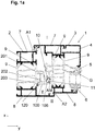
- a frame arrangement 1 for a window or a door comprises according to Fig. 1a and 1b at least a first frame profile and a second frame profile, which are aligned parallel to each other.
- the first frame profile is designed as a frame profile 2 and the second frame profile is designed as a sash profile 3.
- the two frame profiles run parallel to each other. They can be moved relative to one another in a manner not shown, for example they can be swiveled and / or rotated about a horizontal axis or can be turned out in parallel.
- circumferentially closed frames are formed on a window, one of which is referred to as a sash and the other as a frame.
- the frame On a door, the frame can not be circumferentially closed or also be circumferentially closed.
- a surface element such as a glass pane G is inserted into the casement 3. This can be held on the respective casement profile 3 with holding and sealing means such as a glass retaining strip 4 and one or more seals 5, 6.
- the glass pane G extends in one plane (X / Z plane), which is also referred to as the main plane.
- the direction perpendicular to this main plane is defined as the X direction.
- the direction perpendicular to the sheet plane is, for example, the Z direction.
- the glass pane G or more generally the surface element separates a first room I from a second room II, or a room in a building (inside) from the surroundings (outside) when the window is installed in a wall opening of a building.
- the two frame profiles which are movable relative to one another, can abut or almost abut one another in one or more stop areas A1 and A2, in which they overlap one another.
- the rebate area F runs between this stop area. This can also be used as a fitting chamber.
- a stop area is also formed in this area, which is called the middle stop area A M.
- this central stop area A M there are a central seal 100 which is fastened to the one frame profile and a folded projection 10 protruding from the opposite frame profile into the folded area.
- a seal 11 can be arranged, which can additionally seal a gap between the center seal 100 and the rabbet projection 10 or this contact area A M.
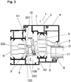
- the center seal 100 can bear with a sealing projection / folding projection 106 on the folding projection 10 and / or the seal 11. To Fig. 3 and 4th the seal 11 of the center seal 100 is in each case on the rabbet projection 10.
- the center seal 100 is formed on the frame profile 2 and the rabbet 10 on the sash profile 3. It extends perpendicular to the image plane of the Fig. 1 and 2nd and is designed as a sealing profile.
- the arrangement can be "reversed” to the extent that the center seal 100 is formed on the casement profile 3 and the rabbet projection 10 on the frame profile 2, as shown in FIG Fig. 4 is shown.
- frame frame profile is not too narrow.
- a profile on the building side such as a central stop profile of a double window with two sashes (see Fig. 1b ) can also form a frame profile 2 in the sense of this document.
- One of the center seals 100 can then also be provided on this, on two sides facing away from one another, in order to seal the corresponding fold area F1, F2 toward each wing.
- An attachment interface is formed between the center seal 100 and the associated frame profile to which it is attached. This has first fastening means on the center seal and corresponding second fastening means on the frame profile to which it is attached.
- the frame profiles 2, 3 are each designed as composite profiles, which have a first and a second material shell, for example a metal shell 7, 8, and an intermediate insulation zone made of plastic insulating profiles 9.
- the second fastening means of the frame profile are formed on or on one of the insulating profiles 9, which connects the two metal shells 7, 8 to one another.
- the second fastening means can be largely distributed arbitrarily on their frame profile in the rebate area. In this way, they could also be additionally or alternatively formed entirely or partially on one or both metal shells / profiles 7, 8 or also formed entirely or partially on one or both metal shells 7, 8.
- One or more of the metal shells could also be made of a different material, such as wood.
- the frame profile for fixing the center seal 100 can also have a structure other than the structure shown, for example it can only consist of metal or plastic. It could also consist of a single metal shell and a single one Be plastic shell assembled. It is essential that there is enough space in the rebate area to distribute the second fastening means there.
- the sealing profile forming the center seal 100 can be bent over with a small radius or be mitered or overlapped.
- the sealing profile or the center seal 100 of the Fig. 1a and 1b is in separately Fig. 2d shown.
- the center seal 100 has a base body 100a.
- This base body 100a can consist of a (first) plastic, which does not have to be an elastomer.
- the base body 100a has an outer wall 101. Here it extends essentially from the inside to the outside in the Y direction. In the assembled state, this outer wall 101 is oriented toward the opposite frame profile.
- the base body 100a can have been produced in an extrusion process (see also 2a to 2e ). It is preferably strip-shaped.
- Wall webs 102, 103, 104, 105 which extend at an angle, in particular completely or almost at right angles to this wall, extend from the outer wall 101 of the base body 100a. In the installed state, these are oriented toward the frame profile to which the center seal 100 is fastened.
- Two outer wall webs 102, 103 are provided.
- the outer contour of the center seal 100 which is visible in the fold in the open state, is formed by the outer wall 101 and the two outer wall webs 102, 103 angled to it. This creates the impression of a trapezoidal sealing structure when the window or door is open.
- a sealing projection 106 preferably projects from the outer sealing lip. This can be bead-like or web-like. It preferably serves as a contact element for contacting the rabbet projection 10 of the opposite frame profile 3.
- center webs 104, 105 are designed as center seal locking webs. They have hook sections 110, 111 at their free ends - that is, at the ends facing away from the first wall 101.
- the hook sections 110, 11 are also referred to synonymously as latching hooks.
- the hook sections 110, 111 at the free ends of the middle seal locking webs can point in opposite directions according to the preferred embodiment shown.
- center webs 104, 105 which are designed as center seal locking webs, are again designed in a straight shape or in a stepped form in all of the variants shown for the center seals 2a, b, c , d and e intended.
- the central webs or here central sealing locking webs 104, 105 can be connected to one another and / or to the outer webs 102, 103 between the wall 101 and their free ends via one or more transverse webs 107.
- one or more hollow chambers H1, H2, H3, ... can also be formed in the center seal 100 (see Fig. 2c , 2d, 2e ).
- the one or more transverse webs 107 can also attach to one of the outer webs 102, 103 or one of the middle webs 104, 405 and cannot extend to a further wall or to another web. In this way, hollow-chamber-like areas are created, which, however, are not designed to be circumferentially closed.
- two or more corresponding locking webs 201, 202, 203 and / or 204 are provided which protrude from the frame profile into the rebate area F.
- These latching webs 201, 202, 203 and / or 204 can - but do not have to - in their interaction also form one or more grooves. They have hook sections or latching hooks 210, 211 at their free ends in the rebate space F.
- the configuration is such that when the center seal 100 is placed on the frame profile to which it is to be fastened (here “2”), the corresponding hook sections 110, 210 and 111, 211 on the center seal 100 and on the frame profile lock together . In this way, the center seal 100 is securely latched and attached to the frame profile to which it is to be attached.
- At least one sealing spring element 120 is arranged between the center seal 100 or its base body and the frame profile. It can also be provided that two or more sealing spring elements 120, 121 are arranged and distributed between the center seal 100 and the frame profile.
- the sealing spring element 120 can be formed on the center seal 100 or its base body.
- the sealing spring element 120 is designed as an elastomer spring 100, which is fixed to the center seal 100, which can also consist of a non-elastomer plastic. This setting can be done by coextrusion, in which, for example, in a two-component extrusion process, the sealing spring element (s) 120 is also formed on the center seal 100 during its manufacture, the center seal 100 per se and the sealing spring element 120 formed thereon being able to consist of different plastics .
- the one or more sealing spring elements 120 could also be an elastic one Adhesive can be realized, which has been pulled along the middle seal or the base body like a cord.
- the sealing spring element 120 can be designed as a sealing profile or sealing cord, which is locked in a groove in the center seal. It is also conceivable that the sealing spring element 120 be designed as a sealing profile or sealing cord that has been glued to the center seal.
- the sealing spring element can also be attached to the base body in a post-extrusion process or can be foamed onto it. It should have a resilient material behavior.
- the design is such that the sealing spring element 120 has been compressed due to the locking of the center seal 100 on the frame profile 2, so that a force acts on the locking connection in the region of one or both of the locking webs, which pushes the center seal 100 away from the frame profile 2, which presses the corresponding hook sections against each other.
- the fit of the center seal 100 on the frame profile 2 is improved in a simple manner.
- the spring travel of the sealing spring element is relatively small parallel to the main direction of extent of the surface element G. In this respect, spring travel of less than 2 mm, preferably less than 1.5 mm, more preferably less than 1.0 mm and particularly preferably less than 0.5 mm have proven successful.
- sealing spring element 120 is preferably in the region of or close to the latching connection, for example between corresponding wall webs which is closest to the sealing projection / folding projection 106. This is because it can be achieved that the sealing projection is pressed into a position which is at a maximum distance from the frame profile 2, which improves the sealing effect in the contact area of the sealing projection on the corresponding sealing surface on the further frame profile in a simple manner.
- one or one of the sealing spring elements 120 below one of the outer wall webs 102, 103 on the other end facing the frame profile.
- one or one of the sealing spring elements 120 lies between a transverse web of the central seal 102 or a central web of the central seal 100 and one of the wall webs of the frame 2 in such a way that, in the assembled state, it lies on the free end of one of the wall webs Presses the hook section of the frame profile.
- the spring force between the center seal 100 and the frame profile - here the frame profile 2 - is particularly advantageous directly in the area of this wall web or locking web.
- the central webs 104, 105 which are designed as latching webs - designed in a straight shape or in a stepped form - are in turn shown in all of the variants shown for the central seals 2a, b, c , d and e intended.
- the sealing profile 100 designed as a center seal is similar Fig. 4 not arranged on the frame profile 2 but on the casement profile 3.
- the folding projection 10 is then formed on the frame profile 2. In this respect, it is a kind of reversal of the solutions of the Fig. 1 and 3rd .
- the sealing profile is in turn designed as a center seal 100.
- FIG. 4 Another advantageous feature that can also be considered separately as an invention.
- the frame profile - here the sash profile 3 - and a strip attached to the frame profile and fastened to it together form a groove 300, in particular an undercut groove.
- This groove can be used as a hardware groove. Then one or more fittings can be arranged and held in it (not shown here).
- the bar can and is after Fig. 4 formed as a strip-shaped base body 100a.
- the base body 100a can be the base body 100a of a center seal 100 (for example, according to the type of Fig. 2 plus another bridge).
- One or more of the sealing spring element (s) 120 can be arranged on the base body 100a. This is advantageous but not essential for this further invention.
- the hardware groove 300 becomes Fig. 4
- one of the metal shells - here the metal shell 7 - (if present :) is formed an insulating profile 9 facing the fold, on which the base body 100a is fixed, and two mutually facing webs 301, 302 on the metal shell 7 and the base body 100a. These webs 301, 302 can preferably run perpendicular to the main extension plane of the surface element G in the fold area.
- a bar (base body 100a and / or center seal 100) that can be retrofitted to a frame profile - in particular a casement profile 3, which can also be designed as a composite profile - is also used to form a fitting groove.
Landscapes
- Engineering & Computer Science (AREA)
- Civil Engineering (AREA)
- Structural Engineering (AREA)
- Specific Sealing Or Ventilating Devices For Doors And Windows (AREA)
Applications Claiming Priority (1)
| Application Number | Priority Date | Filing Date | Title |
|---|---|---|---|
| DE102019100614.7A DE102019100614A1 (de) | 2019-01-11 | 2019-01-11 | Dichtungsprofil für ein Rahmenprofil und Rahmenprofil |
Publications (2)
| Publication Number | Publication Date |
|---|---|
| EP3680438A1 true EP3680438A1 (fr) | 2020-07-15 |
| EP3680438B1 EP3680438B1 (fr) | 2022-07-27 |
Family
ID=69156266
Family Applications (1)
| Application Number | Title | Priority Date | Filing Date |
|---|---|---|---|
| EP20150853.8A Active EP3680438B1 (fr) | 2019-01-11 | 2020-01-09 | Arrangement d'un profilé de cadre et d'un profilé d'étanchéité pour un profilé d'une fenêtre ou porte |
Country Status (4)
| Country | Link |
|---|---|
| EP (1) | EP3680438B1 (fr) |
| DE (1) | DE102019100614A1 (fr) |
| ES (1) | ES2928233T3 (fr) |
| PL (1) | PL3680438T3 (fr) |
Cited By (1)
| Publication number | Priority date | Publication date | Assignee | Title |
|---|---|---|---|---|
| RU221369U1 (ru) * | 2023-09-01 | 2023-11-02 | Максим Александрович Волков | Вставка дверного блока |
Families Citing this family (1)
| Publication number | Priority date | Publication date | Assignee | Title |
|---|---|---|---|---|
| US11976511B2 (en) * | 2021-11-05 | 2024-05-07 | Arconic Technologies Llc | Thermal dampening devices for window systems |
Citations (3)
| Publication number | Priority date | Publication date | Assignee | Title |
|---|---|---|---|---|
| DE3139559A1 (de) * | 1980-10-27 | 1982-10-14 | Voest-Alpine Krems Gesellschaft mbH, 3502 Krems | Feuerhemmende tuer- oder fensterdichtung |
| EP2754842A1 (fr) | 2013-01-11 | 2014-07-16 | SCHÜCO International KG | Profil d'étanchéité pour un profil de cadre et profil de cadre |
| DE102014115422A1 (de) * | 2014-10-23 | 2016-04-28 | SCHÜCO International KG | Fenster oder Tür, insbesondere Blockfenster |
Family Cites Families (3)
| Publication number | Priority date | Publication date | Assignee | Title |
|---|---|---|---|---|
| DE102009056118A1 (de) * | 2009-11-30 | 2011-06-01 | Inge Frey | Dichtung, insbesondere für Schiebetüren |
| DE202010008921U1 (de) | 2010-10-28 | 2010-12-30 | SCHÜCO International KG | Mitteldichtung für hoch wärmegedämmte Fenster oder Türen |
| DE102016125334A1 (de) * | 2016-12-22 | 2018-06-28 | SCHÜCO International KG | Fenster oder Tür mit einer Dichtungsanordnung und Falzdichtung |
-
2019
- 2019-01-11 DE DE102019100614.7A patent/DE102019100614A1/de active Pending
-
2020
- 2020-01-09 ES ES20150853T patent/ES2928233T3/es active Active
- 2020-01-09 PL PL20150853.8T patent/PL3680438T3/pl unknown
- 2020-01-09 EP EP20150853.8A patent/EP3680438B1/fr active Active
Patent Citations (3)
| Publication number | Priority date | Publication date | Assignee | Title |
|---|---|---|---|---|
| DE3139559A1 (de) * | 1980-10-27 | 1982-10-14 | Voest-Alpine Krems Gesellschaft mbH, 3502 Krems | Feuerhemmende tuer- oder fensterdichtung |
| EP2754842A1 (fr) | 2013-01-11 | 2014-07-16 | SCHÜCO International KG | Profil d'étanchéité pour un profil de cadre et profil de cadre |
| DE102014115422A1 (de) * | 2014-10-23 | 2016-04-28 | SCHÜCO International KG | Fenster oder Tür, insbesondere Blockfenster |
Cited By (1)
| Publication number | Priority date | Publication date | Assignee | Title |
|---|---|---|---|---|
| RU221369U1 (ru) * | 2023-09-01 | 2023-11-02 | Максим Александрович Волков | Вставка дверного блока |
Also Published As
| Publication number | Publication date |
|---|---|
| EP3680438B1 (fr) | 2022-07-27 |
| DE102019100614A1 (de) | 2020-07-16 |
| ES2928233T3 (es) | 2022-11-16 |
| PL3680438T3 (pl) | 2022-12-19 |
Similar Documents
| Publication | Publication Date | Title |
|---|---|---|
| EP0786576B1 (fr) | Joint d'étanchéité élastique pour fenêtres, portes ou similaires | |
| WO2016131909A1 (fr) | Dispositif d'étanchéité pour éléments de fenêtre et éléments de porte | |
| AT392327B (de) | Strangfoermige fluegelfalzdichtung fuer fenster, tueren oder dgl. raumabschlussorgane | |
| EP2088275B1 (fr) | Profilé d'étanchéité de côtés, notamment pour profilés de cadre et installations de portes coulissantes en étant équipées | |
| EP0681081A1 (fr) | Fermeture pour ouvertures dans des parois de bâtiments ou similaires | |
| EP3680438B1 (fr) | Arrangement d'un profilé de cadre et d'un profilé d'étanchéité pour un profilé d'une fenêtre ou porte | |
| EP3438395A1 (fr) | Système de cadre de fenêtre | |
| CH708701A2 (de) | Schiebewand. | |
| DE9406202U1 (de) | Fensterflügelrahmen-Hohlprofil und daraus bestehender Doppelflügel-Fensterrahmen | |
| EP4198243B1 (fr) | Agencement de profilé de cadre | |
| EP3216967B1 (fr) | Profilé d'étanchéité pour fenêtres, portes ou façades | |
| DE8712982U1 (de) | Rolladen oder Rolltor | |
| EP3140486B1 (fr) | Porte, fenêtre ou élément de façade comprenant un système d'étanchéité | |
| CH669972A5 (en) | Profiled door-sealing strip - has two-section transverse flange with stiffening rib on inside | |
| EP3569807B1 (fr) | Profilé de raccordement | |
| AT396385B (de) | Stockrahmenprofil | |
| AT389734B (de) | Stalltuer | |
| DE102014103650A1 (de) | Verfahren sowie Profilsystem zur Herstellung von Gebäudefenstern, Gebäudetüren | |
| DE102013204944B4 (de) | Elastische Strangdichtung für Fenster, Türen oder dgl. | |
| DE102014112112A1 (de) | Tür, Fenster oder Fassadenelement mit einem Dichtungsystem | |
| EP3581751B1 (fr) | Cadre pourvu de panneau de parement et système de profilés destiné à sa fabrication | |
| EP1908911A2 (fr) | Construction de cadre à double battant et agencement d'étanchéité | |
| CH669971A5 (en) | Profiled elastic window sealing component | |
| DE102016218255A1 (de) | Gebäudeverschluss | |
| DE202012000179U1 (de) | Schwanenhalsdichtung mit zwei Kammern |
Legal Events
| Date | Code | Title | Description |
|---|---|---|---|
| PUAI | Public reference made under article 153(3) epc to a published international application that has entered the european phase |
Free format text: ORIGINAL CODE: 0009012 |
|
| STAA | Information on the status of an ep patent application or granted ep patent |
Free format text: STATUS: THE APPLICATION HAS BEEN PUBLISHED |
|
| AK | Designated contracting states |
Kind code of ref document: A1 Designated state(s): AL AT BE BG CH CY CZ DE DK EE ES FI FR GB GR HR HU IE IS IT LI LT LU LV MC MK MT NL NO PL PT RO RS SE SI SK SM TR |
|
| AX | Request for extension of the european patent |
Extension state: BA ME |
|
| STAA | Information on the status of an ep patent application or granted ep patent |
Free format text: STATUS: REQUEST FOR EXAMINATION WAS MADE |
|
| 17P | Request for examination filed |
Effective date: 20210112 |
|
| RBV | Designated contracting states (corrected) |
Designated state(s): AL AT BE BG CH CY CZ DE DK EE ES FI FR GB GR HR HU IE IS IT LI LT LU LV MC MK MT NL NO PL PT RO RS SE SI SK SM TR |
|
| GRAP | Despatch of communication of intention to grant a patent |
Free format text: ORIGINAL CODE: EPIDOSNIGR1 |
|
| STAA | Information on the status of an ep patent application or granted ep patent |
Free format text: STATUS: GRANT OF PATENT IS INTENDED |
|
| INTG | Intention to grant announced |
Effective date: 20220209 |
|
| GRAS | Grant fee paid |
Free format text: ORIGINAL CODE: EPIDOSNIGR3 |
|
| GRAA | (expected) grant |
Free format text: ORIGINAL CODE: 0009210 |
|
| STAA | Information on the status of an ep patent application or granted ep patent |
Free format text: STATUS: THE PATENT HAS BEEN GRANTED |
|
| AK | Designated contracting states |
Kind code of ref document: B1 Designated state(s): AL AT BE BG CH CY CZ DE DK EE ES FI FR GB GR HR HU IE IS IT LI LT LU LV MC MK MT NL NO PL PT RO RS SE SI SK SM TR |
|
| REG | Reference to a national code |
Ref country code: CH Ref legal event code: EP |
|
| REG | Reference to a national code |
Ref country code: DE Ref legal event code: R096 Ref document number: 502020001411 Country of ref document: DE |
|
| REG | Reference to a national code |
Ref country code: AT Ref legal event code: REF Ref document number: 1507178 Country of ref document: AT Kind code of ref document: T Effective date: 20220815 |
|
| REG | Reference to a national code |
Ref country code: IE Ref legal event code: FG4D Free format text: LANGUAGE OF EP DOCUMENT: GERMAN |
|
| REG | Reference to a national code |
Ref country code: NL Ref legal event code: FP |
|
| REG | Reference to a national code |
Ref country code: LT Ref legal event code: MG9D |
|
| REG | Reference to a national code |
Ref country code: ES Ref legal event code: FG2A Ref document number: 2928233 Country of ref document: ES Kind code of ref document: T3 Effective date: 20221116 |
|
| PG25 | Lapsed in a contracting state [announced via postgrant information from national office to epo] |
Ref country code: SE Free format text: LAPSE BECAUSE OF FAILURE TO SUBMIT A TRANSLATION OF THE DESCRIPTION OR TO PAY THE FEE WITHIN THE PRESCRIBED TIME-LIMIT Effective date: 20220727 Ref country code: RS Free format text: LAPSE BECAUSE OF FAILURE TO SUBMIT A TRANSLATION OF THE DESCRIPTION OR TO PAY THE FEE WITHIN THE PRESCRIBED TIME-LIMIT Effective date: 20220727 Ref country code: PT Free format text: LAPSE BECAUSE OF FAILURE TO SUBMIT A TRANSLATION OF THE DESCRIPTION OR TO PAY THE FEE WITHIN THE PRESCRIBED TIME-LIMIT Effective date: 20221128 Ref country code: NO Free format text: LAPSE BECAUSE OF FAILURE TO SUBMIT A TRANSLATION OF THE DESCRIPTION OR TO PAY THE FEE WITHIN THE PRESCRIBED TIME-LIMIT Effective date: 20221027 Ref country code: LV Free format text: LAPSE BECAUSE OF FAILURE TO SUBMIT A TRANSLATION OF THE DESCRIPTION OR TO PAY THE FEE WITHIN THE PRESCRIBED TIME-LIMIT Effective date: 20220727 Ref country code: LT Free format text: LAPSE BECAUSE OF FAILURE TO SUBMIT A TRANSLATION OF THE DESCRIPTION OR TO PAY THE FEE WITHIN THE PRESCRIBED TIME-LIMIT Effective date: 20220727 Ref country code: FI Free format text: LAPSE BECAUSE OF FAILURE TO SUBMIT A TRANSLATION OF THE DESCRIPTION OR TO PAY THE FEE WITHIN THE PRESCRIBED TIME-LIMIT Effective date: 20220727 |
|
| PG25 | Lapsed in a contracting state [announced via postgrant information from national office to epo] |
Ref country code: IS Free format text: LAPSE BECAUSE OF FAILURE TO SUBMIT A TRANSLATION OF THE DESCRIPTION OR TO PAY THE FEE WITHIN THE PRESCRIBED TIME-LIMIT Effective date: 20221127 Ref country code: HR Free format text: LAPSE BECAUSE OF FAILURE TO SUBMIT A TRANSLATION OF THE DESCRIPTION OR TO PAY THE FEE WITHIN THE PRESCRIBED TIME-LIMIT Effective date: 20220727 Ref country code: GR Free format text: LAPSE BECAUSE OF FAILURE TO SUBMIT A TRANSLATION OF THE DESCRIPTION OR TO PAY THE FEE WITHIN THE PRESCRIBED TIME-LIMIT Effective date: 20221028 |
|
| PG25 | Lapsed in a contracting state [announced via postgrant information from national office to epo] |
Ref country code: SM Free format text: LAPSE BECAUSE OF FAILURE TO SUBMIT A TRANSLATION OF THE DESCRIPTION OR TO PAY THE FEE WITHIN THE PRESCRIBED TIME-LIMIT Effective date: 20220727 Ref country code: RO Free format text: LAPSE BECAUSE OF FAILURE TO SUBMIT A TRANSLATION OF THE DESCRIPTION OR TO PAY THE FEE WITHIN THE PRESCRIBED TIME-LIMIT Effective date: 20220727 Ref country code: DK Free format text: LAPSE BECAUSE OF FAILURE TO SUBMIT A TRANSLATION OF THE DESCRIPTION OR TO PAY THE FEE WITHIN THE PRESCRIBED TIME-LIMIT Effective date: 20220727 Ref country code: CZ Free format text: LAPSE BECAUSE OF FAILURE TO SUBMIT A TRANSLATION OF THE DESCRIPTION OR TO PAY THE FEE WITHIN THE PRESCRIBED TIME-LIMIT Effective date: 20220727 |
|
| REG | Reference to a national code |
Ref country code: DE Ref legal event code: R097 Ref document number: 502020001411 Country of ref document: DE |
|
| PG25 | Lapsed in a contracting state [announced via postgrant information from national office to epo] |
Ref country code: SK Free format text: LAPSE BECAUSE OF FAILURE TO SUBMIT A TRANSLATION OF THE DESCRIPTION OR TO PAY THE FEE WITHIN THE PRESCRIBED TIME-LIMIT Effective date: 20220727 Ref country code: EE Free format text: LAPSE BECAUSE OF FAILURE TO SUBMIT A TRANSLATION OF THE DESCRIPTION OR TO PAY THE FEE WITHIN THE PRESCRIBED TIME-LIMIT Effective date: 20220727 |
|
| PLBE | No opposition filed within time limit |
Free format text: ORIGINAL CODE: 0009261 |
|
| STAA | Information on the status of an ep patent application or granted ep patent |
Free format text: STATUS: NO OPPOSITION FILED WITHIN TIME LIMIT |
|
| PG25 | Lapsed in a contracting state [announced via postgrant information from national office to epo] |
Ref country code: AL Free format text: LAPSE BECAUSE OF FAILURE TO SUBMIT A TRANSLATION OF THE DESCRIPTION OR TO PAY THE FEE WITHIN THE PRESCRIBED TIME-LIMIT Effective date: 20220727 |
|
| 26N | No opposition filed |
Effective date: 20230502 |
|
| PG25 | Lapsed in a contracting state [announced via postgrant information from national office to epo] |
Ref country code: SI Free format text: LAPSE BECAUSE OF FAILURE TO SUBMIT A TRANSLATION OF THE DESCRIPTION OR TO PAY THE FEE WITHIN THE PRESCRIBED TIME-LIMIT Effective date: 20220727 |
|
| REG | Reference to a national code |
Ref country code: CH Ref legal event code: PL |
|
| P01 | Opt-out of the competence of the unified patent court (upc) registered |
Effective date: 20230815 |
|
| PG25 | Lapsed in a contracting state [announced via postgrant information from national office to epo] |
Ref country code: LU Free format text: LAPSE BECAUSE OF NON-PAYMENT OF DUE FEES Effective date: 20230109 |
|
| PG25 | Lapsed in a contracting state [announced via postgrant information from national office to epo] |
Ref country code: LI Free format text: LAPSE BECAUSE OF NON-PAYMENT OF DUE FEES Effective date: 20230131 Ref country code: CH Free format text: LAPSE BECAUSE OF NON-PAYMENT OF DUE FEES Effective date: 20230131 |
|
| PG25 | Lapsed in a contracting state [announced via postgrant information from national office to epo] |
Ref country code: IE Free format text: LAPSE BECAUSE OF NON-PAYMENT OF DUE FEES Effective date: 20230109 |
|
| PG25 | Lapsed in a contracting state [announced via postgrant information from national office to epo] |
Ref country code: MC Free format text: LAPSE BECAUSE OF FAILURE TO SUBMIT A TRANSLATION OF THE DESCRIPTION OR TO PAY THE FEE WITHIN THE PRESCRIBED TIME-LIMIT Effective date: 20220727 |
|
| PG25 | Lapsed in a contracting state [announced via postgrant information from national office to epo] |
Ref country code: MC Free format text: LAPSE BECAUSE OF FAILURE TO SUBMIT A TRANSLATION OF THE DESCRIPTION OR TO PAY THE FEE WITHIN THE PRESCRIBED TIME-LIMIT Effective date: 20220727 |
|
| PG25 | Lapsed in a contracting state [announced via postgrant information from national office to epo] |
Ref country code: BG Free format text: LAPSE BECAUSE OF FAILURE TO SUBMIT A TRANSLATION OF THE DESCRIPTION OR TO PAY THE FEE WITHIN THE PRESCRIBED TIME-LIMIT Effective date: 20220727 |
|
| PG25 | Lapsed in a contracting state [announced via postgrant information from national office to epo] |
Ref country code: BG Free format text: LAPSE BECAUSE OF FAILURE TO SUBMIT A TRANSLATION OF THE DESCRIPTION OR TO PAY THE FEE WITHIN THE PRESCRIBED TIME-LIMIT Effective date: 20220727 |
|
| PG25 | Lapsed in a contracting state [announced via postgrant information from national office to epo] |
Ref country code: CY Free format text: LAPSE BECAUSE OF FAILURE TO SUBMIT A TRANSLATION OF THE DESCRIPTION OR TO PAY THE FEE WITHIN THE PRESCRIBED TIME-LIMIT; INVALID AB INITIO Effective date: 20200109 |
|
| PG25 | Lapsed in a contracting state [announced via postgrant information from national office to epo] |
Ref country code: HU Free format text: LAPSE BECAUSE OF FAILURE TO SUBMIT A TRANSLATION OF THE DESCRIPTION OR TO PAY THE FEE WITHIN THE PRESCRIBED TIME-LIMIT; INVALID AB INITIO Effective date: 20200109 |
|
| PG25 | Lapsed in a contracting state [announced via postgrant information from national office to epo] |
Ref country code: TR Free format text: LAPSE BECAUSE OF FAILURE TO SUBMIT A TRANSLATION OF THE DESCRIPTION OR TO PAY THE FEE WITHIN THE PRESCRIBED TIME-LIMIT Effective date: 20220727 |
|
| PGFP | Annual fee paid to national office [announced via postgrant information from national office to epo] |
Ref country code: PL Payment date: 20251219 Year of fee payment: 7 |
|
| PGFP | Annual fee paid to national office [announced via postgrant information from national office to epo] |
Ref country code: NL Payment date: 20260108 Year of fee payment: 7 |
|
| PGFP | Annual fee paid to national office [announced via postgrant information from national office to epo] |
Ref country code: GB Payment date: 20260106 Year of fee payment: 7 |
|
| PGFP | Annual fee paid to national office [announced via postgrant information from national office to epo] |
Ref country code: ES Payment date: 20260217 Year of fee payment: 7 |
|
| PGFP | Annual fee paid to national office [announced via postgrant information from national office to epo] |
Ref country code: DE Payment date: 20251222 Year of fee payment: 7 |
|
| PGFP | Annual fee paid to national office [announced via postgrant information from national office to epo] |
Ref country code: AT Payment date: 20260108 Year of fee payment: 7 |
|
| PGFP | Annual fee paid to national office [announced via postgrant information from national office to epo] |
Ref country code: BE Payment date: 20260108 Year of fee payment: 7 Ref country code: IT Payment date: 20260130 Year of fee payment: 7 |
|
| PGFP | Annual fee paid to national office [announced via postgrant information from national office to epo] |
Ref country code: FR Payment date: 20260106 Year of fee payment: 7 |