EP3682763B1 - Auszugsführung für eine schublade mit integrierter abhebesicherung - Google Patents
Auszugsführung für eine schublade mit integrierter abhebesicherung Download PDFInfo
- Publication number
- EP3682763B1 EP3682763B1 EP19208811.0A EP19208811A EP3682763B1 EP 3682763 B1 EP3682763 B1 EP 3682763B1 EP 19208811 A EP19208811 A EP 19208811A EP 3682763 B1 EP3682763 B1 EP 3682763B1
- Authority
- EP
- European Patent Office
- Prior art keywords
- rail
- rope
- drawer
- pull
- out guide
- Prior art date
- Legal status (The legal status is an assumption and is not a legal conclusion. Google has not performed a legal analysis and makes no representation as to the accuracy of the status listed.)
- Active
Links
Images


Classifications
-
- A—HUMAN NECESSITIES
- A47—FURNITURE; DOMESTIC ARTICLES OR APPLIANCES; COFFEE MILLS; SPICE MILLS; SUCTION CLEANERS IN GENERAL
- A47B—TABLES; DESKS; OFFICE FURNITURE; CABINETS; DRAWERS; GENERAL DETAILS OF FURNITURE
- A47B88/00—Drawers for tables, cabinets or like furniture; Guides for drawers
- A47B88/40—Sliding drawers; Slides or guides therefor
- A47B88/44—Sequencing or synchronisation of drawer slides or functional units
- A47B88/447—Simultaneous movement of rails within drawer slides, i.e. with a coordination of movement with all rail elements moving at the same time
-
- A—HUMAN NECESSITIES
- A47—FURNITURE; DOMESTIC ARTICLES OR APPLIANCES; COFFEE MILLS; SPICE MILLS; SUCTION CLEANERS IN GENERAL
- A47B—TABLES; DESKS; OFFICE FURNITURE; CABINETS; DRAWERS; GENERAL DETAILS OF FURNITURE
- A47B88/00—Drawers for tables, cabinets or like furniture; Guides for drawers
- A47B88/40—Sliding drawers; Slides or guides therefor
- A47B88/49—Sliding drawers; Slides or guides therefor with double extensible guides or parts
- A47B88/493—Sliding drawers; Slides or guides therefor with double extensible guides or parts with rollers, ball bearings, wheels, or the like
-
- A—HUMAN NECESSITIES
- A47—FURNITURE; DOMESTIC ARTICLES OR APPLIANCES; COFFEE MILLS; SPICE MILLS; SUCTION CLEANERS IN GENERAL
- A47B—TABLES; DESKS; OFFICE FURNITURE; CABINETS; DRAWERS; GENERAL DETAILS OF FURNITURE
- A47B2210/00—General construction of drawers, guides and guide devices
- A47B2210/0002—Guide construction for drawers
- A47B2210/0064—Guide sequencing or synchronisation
- A47B2210/0072—Coordinating mechanisms for sequential drawer slides, e.g. by cable
Definitions
- the invention relates to a pull-out slide for a drawer according to the preamble of claim 1.
- Such a pull-out guide is for example by US 2016/128475 A1 known.
- the combination of a drawer and such a pull-out guide can be configured with a comparatively low height, since the drawer can be placed directly on the drawer rail.
- support rollers can be rotatably mounted on the side of the middle rail. Further support rollers for supporting the drawer rail can be attached to the carcass rail, which prevent the drawer rail from falling, in particular after a drawer has been loaded onto the rail package.
- the DE 39 36 754 A1 discloses a synchronized drawer slide or pull-out slide with a body rail, a pull-out rail or middle rail and a drawer rail.
- the body rail is connected to a tension element via a head.
- the tension element encloses the pull-out rail via pulleys.
- the drawer rail is firmly connected to the tension element via a fastening. In the retracted position, the pull-out rail lies within the U-shaped drawer rail.
- the pulling element is moved over the fastening and takes the pull-out rail with it via the pulleys. This also pulls out the pull-out rail.
- the cabinet rail is firmly connected to the side wall of a cabinet using screws.
- the drawer rail and the pull-out rail are supported in the vertical and horizontal direction by means of guide rollers.
- a drawer slide is also known in which the rail movement is synchronized by a traction mechanism.
- a carriage attached to the middle rail ensures that the rails run free of play.
- a drawer slide with a drawer rail, a center rail and a body rail is known, with carriages rolling between the rails in a load-transmitting manner.
- a traction means is provided which runs over deflection rollers arranged on the center rail.
- the upper run of the traction means is connected to the two ends of an upper carriage, while the lower run of the traction means is connected to the ends of a lower carriage.
- DE 10 2013 113 671 A1 discloses a guide device for linearly movable components with a guide rail along which a support element is mounted so as to be movable via rollers or rolling elements.
- the support element can be moved linearly between two end positions and a support device is provided between support element and guide rail in at least one end position, the support element being supported by the support device only when a predetermined force is exceeded in one of the end positions. In this way, deformation of the rolling elements or rollers in a stationary end position can be reduced.
- a pull-out slide with the features of claim 1.
- the rope pulley is used to guide the rope device and at the same time to prevent the drawer rail from being lifted off, namely in the direction perpendicular to the axis of rotation of the rope pulley, i.e. upwards when the pull-out guide is installed.
- No other structural components in addition to the rope pulleys are required to secure against lifting.
- no additional support rollers are required on the center rail for the extended state of the rail package.
- the cable device can be integrated or integrated into the drawer rail. As a result, there are fewer problems during transport due to protruding rope components and no damage to the rope device during guide assembly by the end user.
- the cable device is attached to the drawer rail and the body rail by means of corresponding brackets.
- the flange also engages under the rear pulley in the pull-out direction.
- the rope pulley preferably has an inner pulley section on which the rope device runs, and an outer pulley section which the flange engages under.
- the outer roller section can have a smaller roller diameter than the inner roller section in order to prevent the flange from colliding with the cable device.
- the rope device can for example be designed as a self-contained rope that runs around the rope pulleys and is attached to both the drawer rail and the body rail, or as an open rope, the two ends of which are either on the drawer rail or on the body rail are attached.
- the cable device can also be formed by two cables which are each guided around a cable pulley and are fastened with one of their cable ends to the drawer rail and with their other cable end to the body rail.
- the drawer rail is advantageously designed as a C-rail profile, one of which is bent free profile end and forms the flange.
- the pull-out guide 10 shown comprises a carcass rail 12 that can be fastened to a carcass, a drawer rail 14 that can be fastened to a drawer in the form of a downwardly open rail profile, one that can be moved both on the carcass rail 12 and on the drawer rail 14 mounted middle rail 16 , as well as a synchronization mechanism 20 for the synchronous movement of the middle rail 16 with the drawer rail 14.
- the drawer rail 14 is only shown in dashed lines for the sake of clarity.
- the synchronization mechanism 20 has a rear pulley 22a and a front pulley 22b in the extension direction A of the pullout guide 10, both of which are attached to the central rail 16, as well as a self-contained rope 24 which runs around the pulleys 22a, 22b.
- Figs. 3a, 3b the middle rail 16 with the two rope pulleys 22a, 22b and the revolving rope 24 is shown.
- the cable 24 is attached to the drawer rail 14 at 28a and to the body rail 12 at 28b.
- the center rail 16 is moved synchronously with the drawer rail 14, namely at half the speed of the drawer rail 14.
- both pulleys 22a, 22b are inside the drawer rail 14, when the drawer rail 14 is fully extended however, only the front pulley 22b.
- the rope can alternatively also be designed as an open rope, the two rope ends of which are then both fastened either to the body rail 12 or to the drawer rail 14.
- two ropes in the form of half-loops can be used, each of which runs around a rope pulley 22a, 22b and is attached with one end of the rope to the body rail 12 and the other end of the rope to the drawer rail 14.
- the drawer rail 14 at the free lower edge of its vertical profile leg has an inwardly bent, horizontal flange 30 , which engages under both pulley 22a, 22b in the retracted state and only the front pulley 22b in the fully extended state, in order to lift the drawer rail 14 to prevent the middle rail 16.
- the rope pulleys 22a, 22b each have an inner pulley section 26 with a larger pulley diameter, on which the rope 24 runs, and an outer pulley section 27 with a smaller pulley diameter, which the flange 30 engages under.
- the outer roller section 27 half the roller diameter of the inner roller section 26.
- the annular shoulder 29 formed between the two roller sections 26, 27 prevents the flange 30 from colliding with the cable 24.
- the pulleys 22a, 22b can, as in FIG Fig. 4 shown, roll on the flange 30 or alternatively also be at a slight distance from the flange 30.
- the two roller sections 26, 27 can also have the same roller diameter, in which case, however, there is no annular shoulder as a collision protection.
- the drawer rail 14 is designed as a C-profile, one of which is bent free profile end and forms the flange 30.
Landscapes
- Drawers Of Furniture (AREA)
Description
- Die Erfindung betrifft eine Auszugsführung für eine Schublade gemäß dem Oberbegriff von Anspruch 1.
- Eine derartige Auszugsführung ist beispielsweise durch die
US 2016/128475 A1 bekannt geworden. - Es ist bekannt, dass die Kombination aus Schublade und einer solchen Auszugsführung sich mit vergleichsweise geringer Höhe ausgestalten lässt, da sich die Schublade direkt auf die Schubladenschiene aufsetzen lässt. Zur Abstützung der Mittelschiene bei gleichzeitiger Kompaktheit in der Höhe lassen sich Stützrollen seitlich an der Mittelschiene drehend lagern. Weitere Stützrollen zum Abstützen der Schubladenschiene lassen sich an der Korpusschiene anbringen, die ein Absinken der Schubladenschiene verhindern, insbesondere nach dem Beladen einer Schublade auf dem Schienenpaket.
- Die
DE 39 36 754 A1 offenbart eine synchronisierte Schubladenführung bzw. Auszugsführung mit einer Korpusschiene, einer Auszugsschiene bzw. Mittelschiene und einer Schubladenschiene. Die Korpusschiene ist über einen Kopf mit einem Zugelement verbunden. Das Zugelement umschließt über Umlenkrollen die Auszugsschiene. Die Schubladenschiene ist über eine Befestigung fest mit dem Zugelement verbunden. In eingefahrener Stellung liegt die Auszugsschiene innerhalb der U-förmigen Schubladenschiene. Durch eine Auszugsbewegung der Schubladenschiene wird das Zugelement über die Befestigung verschoben und nimmt über die Umlenkrollen die Auszugsschiene mit. Dadurch wird die Auszugsschiene ebenfalls mit ausgezogen. Die Korpusschiene ist über Schrauben fest mit der Seitenwand eines Korpus verbunden. Die Abstützung der Schubladenschiene und der Auszugsschiene in vertikaler und horizontaler Richtung erfolgt jeweils über Führungsrollen. - Aus der
DE 40 19 124 C2 ist ebenfalls eine Schubladenführung bekannt, bei der die Schienenbewegung durch ein Zugmittel synchronisiert ist. Dabei wird durch einen an der Mittelschiene angebrachten Laufwagen ein spielfreier Lauf der Schienen erzielt. - Bei den genannten Schubladenführungen werden zur Abstützung und als Abhebesicherung der Schubladenschiene zusätzlich zu dem Synchronisierungsmechanismus und den Schienen weitere Baukomponenten in Form von Führungsrollen oder Laufwagen benötigt.
- Die eingangs genannte
US 2016/128475 A1 offenbart eine Auszugsführung mit einer stationären Schiene und einer relativ zu der stationären Schiene verfahrbare Schiene sowie mit Mitteln zur Synchronisierung der Bewegung der verfahrbaren Schienen, die ein flexibles Umlenkelement z.B. in Form eines Drahtseils umfassen. Dadurch können auch breite oder schwere Auszüge auf einfache Weise und geräuscharm in der Bewegung synchronisiert werden. - Aus der
DE 42 26 812 A1 ist eine Schubladenführung mit einer Schubladenschiene, einer Mittelschiene und einer Korpusschiene bekannt, wobei zwischen den Schienen Laufwagen lastübertragend sich abwälzen. Um eine synchrone Verschiebung der Mittelschiene bei der Verschiebung der Schubladenschiene zu erreichen, ist ein Zugmittel vorgesehen, welches über an der Mittelschiene angeordnete Umlenkrollen läuft. Das obere Trum des Zugmittels ist mit den beiden Enden eines oberen Laufwagens verbunden, während das untere Trum des Zugmittels mit den Enden eines unteren Laufwagens verbunden ist. -
DE 10 2013 113 671 A1 offenbart eine Führungsvorrichtung für linear bewegbare Bauteile mit einer Führungsschiene, entlang der ein Tragelement über Rollen oder Wälzkörper verfahrbar gelagert ist,. Das Tragelement ist zwischen zwei Endpositionen linear verfahrbar und in mindestens einer Endposition ist eine Stützeinrichtung zwischen Tragelement und Führungsschiene vorgesehen, wobei erst bei Überschreiten einer vorbestimmten Kraft in einer der Endpositionen das Tragelement durch die Stützeinrichtung abgestützt ist. Dadurch kann eine Verformung der Wälzkörper oder Rollen in einer stationären Endposition verringert werden. Demgegenüber ist es die Aufgabe der Erfindung, eine Auszugsführung bereitzustellen, bei der der Synchronisierungsmechanismus und die Schubladenschiene eine integrierte Abhebesicherung der Schubladenschiene ohne weitere Baukomponenten aufweisen. - Diese Aufgabe wird erfindungsgemäß durch eine Auszugsführung mit den Merkmalen von Anspruch 1 gelöst. Die Seilrolle dient der Führung der Seileinrichtung und gleichzeitig als Abhebesicherung für die Schubladenschiene, und zwar in Richtung senkrecht zu der Drehachse der Seilrolle, also bei montierter Auszugsführung nach oben. Weitere Baukomponenten zusätzlich zu den Seilrollen werden zur Abhebesicherung nicht benötigt. Insbesondere sind keine zusätzlichen Stützrollen an der Mittelschiene für den ausgezogenen Zustand des Schienenpakets notwendig. Es wird auch keine Stützrollenbaugruppe für den eingeschobenen Zustand benötigt. Die Seileinrichtung ist in die Schubladenschiene integrierbar bzw. integriert. Dadurch gibt es weniger Probleme beim Transport durch abstehende Seilkomponenten und keine Beschädigung der Seileinrichtung bei der Führungsmontage durch den Endanwender. Die Seileinrichtung ist durch entsprechende Halterungen an der Schubladenschiene und der Korpusschiene befestigt.
- In einer vorteilhaften Ausführungsform der Erfindung ist zumindest bei eingefahrener Schubladenschiene auch die in Ausziehrichtung hintere Seilrolle von dem Flansch untergriffen.
- Vorzugsweise weist die Seilrolle einen innen liegenden Rollenabschnitt, auf dem die Seileinrichtung läuft, und einen außen liegenden Rollenabschnitt, der von dem Flansch untergriffen ist, auf. Dabei kann der außen liegende Rollenabschnitt einen kleineren Rollendurchmesser aufweisen als der innen liegende Rollenabschnitt, um so zu verhindern, dass der Flansch mit der Seileinrichtung kollidiert.
- Die Seileinrichtung kann beispielsweise als ein in sich geschlossenes Seil, das auf den Seilrollen umläuft und sowohl an der Schubladenschiene als auch an der Korpusschiene befestigt ist, oder als ein offenes Seil ausgebildet sein, dessen zwei Seilenden beide entweder an der Schubladenschiene oder an der Korpusschiene befestigt sind. Alternativ kann die Seileinrichtung aber auch durch zwei Seile gebildet sein, die jeweils um eine Seilrolle geführt sind und mit ihrem einen Seilende an der Schubladenschiene und mit ihrem anderen Seilende an der Korpusschiene befestigt sind.
- Vorteilhaft ist die Schubladenschiene als C-Schienenprofil ausgebildet, dessen eines umgebogenes freies Profilende den Flansch ausbildet.
- Weitere Vorteile der Erfindung ergeben sich aus der Beschreibung, den Ansprüchen und der Zeichnung. Ebenso können die vorstehend genannten und die noch weiter aufgeführten Merkmale je für sich oder zu mehreren in beliebigen Kombinationen Verwendung finden. Die gezeigten und beschriebenen Ausführungsformen sind nicht als abschließende Aufzählung zu verstehen, sondern haben vielmehr beispielhaften Charakter für die Schilderung der Erfindung.
- Es zeigen:
- Fign. 1a, 1b
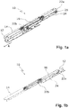
- eine perspektivische Ansicht einer erfindungsgemäßen Auszugsführung für eine Schublade im eingefahrenen Zustand (
Fig. 1a ) und im vollständig ausgezogenen Zustand (Fig. 1b ); - Fign. 2a, 2b
- eine Seitenansicht der erfindungsgemäßen Auszugsführung im eingefahrenen Zustand (
Fig. 2a ) und im vollständig ausgezogenen Zustand (Fig. 2b ); - Fign. 3a, 3b
- eine Mittelschiene der erfindungsgemäßen Auszugsführung in einer perspektivischen Ansicht (
Fig. 3a ) und in einer Seitenansicht (Fig. 3b ); und - Fig. 4
- einen Querschnitt durch die erfindungsgemäßen Auszugsführung im Bereich einer Seilrolle der Mittelschiene.
- Die in den
Fign. 1 und2 gezeigte Auszugsführung 10 umfasst eine an einem Korpus befestigbare Korpusschiene 12, eine an einer Schublade befestigbare Schubladenschiene 14 in Form eines nach unten offenen Schienenprofils, eine sowohl an der Korpusschiene 12 als auch an der Schubladenschiene 14 verschiebbar gelagerte Mittelschiene 16, sowie einen Synchronisationsmechanismus 20 zum synchronen Verfahren der Mittelschiene 16 mit der Schubladenschiene 14. Die Schubladenschiene 14 ist der Übersichtlichkeit halber nur gestrichelt dargestellt. Der Synchronisationsmechanismus 20 weist eine in Auszugsrichtung A der Auszugsführung 10 hintere Seilrolle 22a und eine vordere Seilrolle 22b, die beide an der Mittelschiene 16 befestigt sind, sowie ein in sich geschlossenes Seil 24 auf, das auf den Seilrollen 22a, 22b umläuft. InFign. 3a, 3b ist die Mittelschiene 16 mit den beiden Seilrollen 22a, 22b und dem umlaufenden Seil 24 gezeigt. - Das Seil 24 ist bei 28a an der Schubladenschiene 14 und bei 28b an der Korpusschiene 12 befestigt. Dadurch wird beim Ein- und Ausfahren der Schubladenschiene 14 die Mittelschiene 16 synchron zu der Schubladenschiene 14 mitbewegt, und zwar mit halber Geschwindigkeit der Schubladenschiene 14. Bei eingefahrener Schubladenschiene 14 befinden sich beide Seilrollen 22a, 22b innerhalb der Schubladenschiene 14, bei vollständig ausgezogener Schubladenschiene 14 hingegen noch nur die vordere Seilrolle 22b.
- Statt wie in
Fign. 1 und2 als ein in sich geschlossenes Seil kann das Seil alternativ auch als ein offenes Seil ausgebildet sein, dessen zwei Seilenden dann beide entweder an der Korpusschiene 12 oder an der Schubladenschiene 14 befestigt sind. Statt eines einzigen Seils können auch zwei Seile in Form von Halbschleifen eingesetzt werden, die jeweils um eine Seilrolle 22a, 22b umlaufen und mit ihrem einen Seilende an der Korpusschiene 12 und mit ihrem anderen Seilende an der Schubladenschiene 14 befestigt sind. - Wie in
Fig. 4 gezeigt ist, hat die Schubladenschiene 14 am freien unteren Rand ihres vertikalen Profilschenkels einen nach innen umgebogenen, horizontalen Flansch 30, der im eingefahrenen Zustand beide Seilrolle 22a, 22b und im vollständig ausgezogenen Zustand nur die vordere Seilrolle 22b untergreift, um so ein Abheben der Schubladenschiene 14 von der Mittelschiene 16 zu verhindern. Die Seilrollen 22a, 22b weisen jeweils einen innen liegenden Rollenabschnitt 26 mit größerem Rollendurchmesser, auf dem das Seil 24 läuft, und einen außen liegenden Rollenabschnitt 27 mit kleinerem Rollendurchmesser auf, der von dem Flansch 30 untergriffen ist. Beispielsweise weist der äußere Rollenabschnitt 27 den halben Rollendurchmesser des inneren Rollenabschnitts 26 auf. Durch den zwischen den beiden Rollenabschnitten 26, 27 gebildeten Ringabsatz 29 wird verhindert, dass der Flansch 30 mit dem Seil 24 kollidiert. Der umgebogene Flansch 30 und der untergriffene, äußere Rollenabschnitt 27 bilden somit eine Abhebesicherung der Schubladenschiene 14. - Die Seilrollen 22a, 22b können, wie in
Fig. 4 gezeigt, auf dem Flansch 30 abrollen oder alternativ auch von dem Flansch 30 geringfügig beabstandet sein. - Statt unterschiedliche Rollendurchmesser können die beiden Rollenabschnitte 26, 27 auch den gleichen Rollendurchmesser aufweisen, wobei dann allerdings kein Ringabsatz als Kollisionsschutz vorhanden ist.
- Im gezeigten Ausführungsbeispiel ist die Schubladenschiene 14 als ein C-Profil ausgeführt, dessen eines umgebogenes freies Profilende den Flansch 30 ausbildet.
Claims (8)
- Auszugsführung (10) für eine Schublademit einer an einem Korpus befestigbaren Korpusschiene (12),mit einer an einer Schublade befestigbaren Schubladenschiene (14), die einen Flansch (30) aufweist,mit einer sowohl an der Korpus- als auch an der Schubladenschiene (12, 14) verschiebbar gelagerten Mittelschiene (16) undmit einem Synchronisationsmechanismus (20) zum synchronen Bewegen der Mittelschiene (16) mit der Schubladenschiene (14),wobei der Synchronisationsmechanismus (20) zwei Seilrollen (22a, 22b), die an der Mittelschiene (16) befestigt sind, und eine Seileinrichtung (24) aufweist, die um die Seilrollen (22a, 22b) geführt und sowohl an der Korpus- als auch an der Schubladenschiene (12, 14) befestigt ist,dadurch gekennzeichnet,dass bei montierter Auszugsführung (10) der Flansch (30) die in Ausziehrichtung (A) vordere Seilrolle (22b) untergreift, die somit als Abhebesicherung für die Schubladenschiene (14) in Richtung nach oben dient.
- Auszugsführung nach Anspruch 1, dadurch gekennzeichnet, dass zumindest bei eingefahrener Schubladenschiene (14) auch die in Ausziehrichtung (A) hintere Seilrolle (22a) von dem Flansch (30) untergriffen ist.
- Auszugsführung nach Anspruch 1 oder 2, dadurch gekennzeichnet, dass die Seilrolle (22a, 22b) einen innen liegenden Rollenabschnitt (26), auf dem die Seileinrichtung (24) läuft, und einen außen liegenden Rollenabschnitt (27), der von dem Flansch (30) untergriffen ist, aufweist.
- Auszugsführung nach Anspruch 3, dadurch gekennzeichnet, dass der außen liegende Rollenabschnitt (27) einen kleineren Rollendurchmesser aufweist als der innen liegende Rollenabschnitt (26).
- Auszugsführung nach einem der vorhergehenden Ansprüche, dadurch gekennzeichnet, dass die Seileinrichtung (24) als ein in sich geschlossenes Seil ausgebildet ist, das auf den Seilrollen (22a, 22b) umläuft und sowohl an der Schubladenschiene (14) als auch an der Korpusschiene (12) befestigt ist.
- Auszugsführung nach einem der Ansprüche 1 bis 4, dadurch gekennzeichnet, dass die Seileinrichtung (24) als ein offenes Seil ausgebildet sein, dessen zwei Seilenden beide entweder an der Schubladenschiene (14) oder an der Korpusschiene (12) befestigt sind.
- Auszugsführung nach einem der Ansprüche 1 bis 4, dadurch gekennzeichnet, dass die Seileinrichtung (24) durch zwei Seile gebildet ist, die jeweils um eine Seilrolle (22a, 22b) geführt sind und mit ihrem einen Seilende an der Schubladenschiene (14) und mit ihrem anderen Seilende an der Korpusschiene (12) befestigt sind.
- Auszugsführung nach einem der vorhergehenden Ansprüche, dadurch gekennzeichnet, dass die Schubladenschiene (14) als C-Schienenprofil ausgebildet ist.
Applications Claiming Priority (1)
| Application Number | Priority Date | Filing Date | Title |
|---|---|---|---|
| DE202019100247.6U DE202019100247U1 (de) | 2019-01-17 | 2019-01-17 | Auszugsführung für eine Schublade mit integrierter Abhebesicherung |
Publications (2)
| Publication Number | Publication Date |
|---|---|
| EP3682763A1 EP3682763A1 (de) | 2020-07-22 |
| EP3682763B1 true EP3682763B1 (de) | 2021-09-01 |
Family
ID=65363863
Family Applications (1)
| Application Number | Title | Priority Date | Filing Date |
|---|---|---|---|
| EP19208811.0A Active EP3682763B1 (de) | 2019-01-17 | 2019-11-13 | Auszugsführung für eine schublade mit integrierter abhebesicherung |
Country Status (3)
| Country | Link |
|---|---|
| EP (1) | EP3682763B1 (de) |
| DE (1) | DE202019100247U1 (de) |
| ES (1) | ES2894238T3 (de) |
Families Citing this family (2)
| Publication number | Priority date | Publication date | Assignee | Title |
|---|---|---|---|---|
| CN114365913A (zh) * | 2022-01-24 | 2022-04-19 | 江苏星徽精密科技有限公司 | 一种用绳索驱动的同步滑轨 |
| DE102023130065A1 (de) * | 2023-10-31 | 2025-04-30 | Paul Hettich Gmbh & Co. Kg | Auszugsführung und Verfahren zur Montage einer Auszugsführung |
Family Cites Families (7)
| Publication number | Priority date | Publication date | Assignee | Title |
|---|---|---|---|---|
| DE3936754A1 (de) | 1989-11-04 | 1991-05-08 | Grass Ag | Schubladenfuehrung mit auszugsschiene |
| DE4019124C2 (de) | 1990-06-15 | 1994-06-01 | Grass Ag | Vollauszug |
| DE4226812B4 (de) * | 1992-08-13 | 2004-10-21 | Grass Gmbh | Schubladenführung mit Vollauszug und Zugmittel |
| DE102010060584A1 (de) * | 2010-11-16 | 2012-05-16 | Paul Hettich Gmbh & Co. Kg | Auszugsführung in Form eines Vollauszuges für ein Auszugsteil eines Möbels |
| DE102010060583A1 (de) * | 2010-11-16 | 2012-05-16 | Paul Hettich Gmbh & Co. Kg | Auszugsführung für ein Auszugsteil eines Möbels |
| DE102013113672A1 (de) * | 2013-06-14 | 2014-12-18 | Paul Hettich Gmbh & Co. Kg | Auszugssystem |
| DE102013113671A1 (de) * | 2013-12-09 | 2015-06-11 | Paul Hettich Gmbh & Co. Kg | Führungsvorrichtung für linear bewegbare Bauteile |
-
2019
- 2019-01-17 DE DE202019100247.6U patent/DE202019100247U1/de active Active
- 2019-11-13 EP EP19208811.0A patent/EP3682763B1/de active Active
- 2019-11-13 ES ES19208811T patent/ES2894238T3/es active Active
Also Published As
| Publication number | Publication date |
|---|---|
| ES2894238T3 (es) | 2022-02-14 |
| DE202019100247U1 (de) | 2019-01-25 |
| EP3682763A1 (de) | 2020-07-22 |
Similar Documents
| Publication | Publication Date | Title |
|---|---|---|
| EP3217838B1 (de) | Klapptisch | |
| EP3568561B1 (de) | Anordnung zur führung einer schiebetür oder falt-schiebetür an einer möbelwand | |
| EP2538818B1 (de) | Ausziehführung für schubladen | |
| DE102007063705B4 (de) | Rollo mit Lochbandantrieb | |
| AT15602U2 (de) | Seilwindenanordnung | |
| CH682247A5 (de) | ||
| EP2974623A1 (de) | Elektromotorisch verstellbare stützeinrichtung | |
| DE3750042T2 (de) | Leisten- Öffnungs- und-Schliessantriebsmechanismus für Fensterläden. | |
| EP3682763B1 (de) | Auszugsführung für eine schublade mit integrierter abhebesicherung | |
| EP2703329A1 (de) | Aufzug | |
| EP2634341A2 (de) | Falttor mit zwei oder mehreren in sich starren Faltladenelementen mit abwechselnd nicht ausknickenden und ausknickenden Elementkanten sowie Betätigungsvorrichtung hierfür | |
| AT401603B (de) | Schubladenführung mit auszugschiene | |
| DE3344359A1 (de) | Fenstermarkise | |
| WO2017070722A1 (de) | Schubladenausziehführung | |
| EP3833837B1 (de) | Vorrichtung zum schliessen der schiebetür einer schiebetüranordnung | |
| DE8803719U1 (de) | Garagenschwingtor mit nicht ausschwenkendem Torblatt | |
| EP2902580B2 (de) | Teleskopschiebetüranlage | |
| EP1908915A2 (de) | Montageverfahren für Rolltor | |
| AT11855U1 (de) | Schubladenausziehführung | |
| EP1671917A1 (de) | Aufzugsanlage mit Schachttüre und Türschliessvorrichtung | |
| EP4065802B1 (de) | Tor für eine garage, halle und dergleichen mit einem verschlusssystem zum öffnen und schliessen der toröffnung | |
| EP4091970B1 (de) | Vorrichtung zum heben von lasten | |
| DE19544896C1 (de) | Markise mit höhenarretierbarer Markisolettengarnitur und verriegelbarem Markisolettenarm | |
| CH686794A5 (de) | Store. | |
| DE202017104052U1 (de) | Laufschienenanordnung für ein Sektionaltor |
Legal Events
| Date | Code | Title | Description |
|---|---|---|---|
| PUAI | Public reference made under article 153(3) epc to a published international application that has entered the european phase |
Free format text: ORIGINAL CODE: 0009012 |
|
| STAA | Information on the status of an ep patent application or granted ep patent |
Free format text: STATUS: THE APPLICATION HAS BEEN PUBLISHED |
|
| STAA | Information on the status of an ep patent application or granted ep patent |
Free format text: STATUS: REQUEST FOR EXAMINATION WAS MADE |
|
| AK | Designated contracting states |
Kind code of ref document: A1 Designated state(s): AL AT BE BG CH CY CZ DE DK EE ES FI FR GB GR HR HU IE IS IT LI LT LU LV MC MK MT NL NO PL PT RO RS SE SI SK SM TR |
|
| AX | Request for extension of the european patent |
Extension state: BA ME |
|
| 17P | Request for examination filed |
Effective date: 20200707 |
|
| RBV | Designated contracting states (corrected) |
Designated state(s): AL AT BE BG CH CY CZ DE DK EE ES FI FR GB GR HR HU IE IS IT LI LT LU LV MC MK MT NL NO PL PT RO RS SE SI SK SM TR |
|
| STAA | Information on the status of an ep patent application or granted ep patent |
Free format text: STATUS: EXAMINATION IS IN PROGRESS |
|
| 17Q | First examination report despatched |
Effective date: 20200917 |
|
| GRAP | Despatch of communication of intention to grant a patent |
Free format text: ORIGINAL CODE: EPIDOSNIGR1 |
|
| STAA | Information on the status of an ep patent application or granted ep patent |
Free format text: STATUS: GRANT OF PATENT IS INTENDED |
|
| INTG | Intention to grant announced |
Effective date: 20210506 |
|
| GRAS | Grant fee paid |
Free format text: ORIGINAL CODE: EPIDOSNIGR3 |
|
| GRAA | (expected) grant |
Free format text: ORIGINAL CODE: 0009210 |
|
| STAA | Information on the status of an ep patent application or granted ep patent |
Free format text: STATUS: THE PATENT HAS BEEN GRANTED |
|
| AK | Designated contracting states |
Kind code of ref document: B1 Designated state(s): AL AT BE BG CH CY CZ DE DK EE ES FI FR GB GR HR HU IE IS IT LI LT LU LV MC MK MT NL NO PL PT RO RS SE SI SK SM TR |
|
| REG | Reference to a national code |
Ref country code: GB Ref legal event code: FG4D Free format text: NOT ENGLISH |
|
| REG | Reference to a national code |
Ref country code: CH Ref legal event code: EP Ref country code: AT Ref legal event code: REF Ref document number: 1425281 Country of ref document: AT Kind code of ref document: T Effective date: 20210915 |
|
| REG | Reference to a national code |
Ref country code: DE Ref legal event code: R096 Ref document number: 502019002198 Country of ref document: DE |
|
| REG | Reference to a national code |
Ref country code: IE Ref legal event code: FG4D Free format text: LANGUAGE OF EP DOCUMENT: GERMAN |
|
| REG | Reference to a national code |
Ref country code: LT Ref legal event code: MG9D |
|
| REG | Reference to a national code |
Ref country code: NL Ref legal event code: MP Effective date: 20210901 |
|
| PG25 | Lapsed in a contracting state [announced via postgrant information from national office to epo] |
Ref country code: SE Free format text: LAPSE BECAUSE OF FAILURE TO SUBMIT A TRANSLATION OF THE DESCRIPTION OR TO PAY THE FEE WITHIN THE PRESCRIBED TIME-LIMIT Effective date: 20210901 Ref country code: RS Free format text: LAPSE BECAUSE OF FAILURE TO SUBMIT A TRANSLATION OF THE DESCRIPTION OR TO PAY THE FEE WITHIN THE PRESCRIBED TIME-LIMIT Effective date: 20210901 Ref country code: BG Free format text: LAPSE BECAUSE OF FAILURE TO SUBMIT A TRANSLATION OF THE DESCRIPTION OR TO PAY THE FEE WITHIN THE PRESCRIBED TIME-LIMIT Effective date: 20211201 Ref country code: LT Free format text: LAPSE BECAUSE OF FAILURE TO SUBMIT A TRANSLATION OF THE DESCRIPTION OR TO PAY THE FEE WITHIN THE PRESCRIBED TIME-LIMIT Effective date: 20210901 Ref country code: HR Free format text: LAPSE BECAUSE OF FAILURE TO SUBMIT A TRANSLATION OF THE DESCRIPTION OR TO PAY THE FEE WITHIN THE PRESCRIBED TIME-LIMIT Effective date: 20210901 Ref country code: FI Free format text: LAPSE BECAUSE OF FAILURE TO SUBMIT A TRANSLATION OF THE DESCRIPTION OR TO PAY THE FEE WITHIN THE PRESCRIBED TIME-LIMIT Effective date: 20210901 Ref country code: NO Free format text: LAPSE BECAUSE OF FAILURE TO SUBMIT A TRANSLATION OF THE DESCRIPTION OR TO PAY THE FEE WITHIN THE PRESCRIBED TIME-LIMIT Effective date: 20211201 |
|
| REG | Reference to a national code |
Ref country code: ES Ref legal event code: FG2A Ref document number: 2894238 Country of ref document: ES Kind code of ref document: T3 Effective date: 20220214 |
|
| PG25 | Lapsed in a contracting state [announced via postgrant information from national office to epo] |
Ref country code: PL Free format text: LAPSE BECAUSE OF FAILURE TO SUBMIT A TRANSLATION OF THE DESCRIPTION OR TO PAY THE FEE WITHIN THE PRESCRIBED TIME-LIMIT Effective date: 20210901 Ref country code: LV Free format text: LAPSE BECAUSE OF FAILURE TO SUBMIT A TRANSLATION OF THE DESCRIPTION OR TO PAY THE FEE WITHIN THE PRESCRIBED TIME-LIMIT Effective date: 20210901 Ref country code: GR Free format text: LAPSE BECAUSE OF FAILURE TO SUBMIT A TRANSLATION OF THE DESCRIPTION OR TO PAY THE FEE WITHIN THE PRESCRIBED TIME-LIMIT Effective date: 20211202 |
|
| PG25 | Lapsed in a contracting state [announced via postgrant information from national office to epo] |
Ref country code: IS Free format text: LAPSE BECAUSE OF FAILURE TO SUBMIT A TRANSLATION OF THE DESCRIPTION OR TO PAY THE FEE WITHIN THE PRESCRIBED TIME-LIMIT Effective date: 20220101 Ref country code: SM Free format text: LAPSE BECAUSE OF FAILURE TO SUBMIT A TRANSLATION OF THE DESCRIPTION OR TO PAY THE FEE WITHIN THE PRESCRIBED TIME-LIMIT Effective date: 20210901 Ref country code: SK Free format text: LAPSE BECAUSE OF FAILURE TO SUBMIT A TRANSLATION OF THE DESCRIPTION OR TO PAY THE FEE WITHIN THE PRESCRIBED TIME-LIMIT Effective date: 20210901 Ref country code: RO Free format text: LAPSE BECAUSE OF FAILURE TO SUBMIT A TRANSLATION OF THE DESCRIPTION OR TO PAY THE FEE WITHIN THE PRESCRIBED TIME-LIMIT Effective date: 20210901 Ref country code: PT Free format text: LAPSE BECAUSE OF FAILURE TO SUBMIT A TRANSLATION OF THE DESCRIPTION OR TO PAY THE FEE WITHIN THE PRESCRIBED TIME-LIMIT Effective date: 20220103 Ref country code: NL Free format text: LAPSE BECAUSE OF FAILURE TO SUBMIT A TRANSLATION OF THE DESCRIPTION OR TO PAY THE FEE WITHIN THE PRESCRIBED TIME-LIMIT Effective date: 20210901 Ref country code: EE Free format text: LAPSE BECAUSE OF FAILURE TO SUBMIT A TRANSLATION OF THE DESCRIPTION OR TO PAY THE FEE WITHIN THE PRESCRIBED TIME-LIMIT Effective date: 20210901 Ref country code: CZ Free format text: LAPSE BECAUSE OF FAILURE TO SUBMIT A TRANSLATION OF THE DESCRIPTION OR TO PAY THE FEE WITHIN THE PRESCRIBED TIME-LIMIT Effective date: 20210901 Ref country code: AL Free format text: LAPSE BECAUSE OF FAILURE TO SUBMIT A TRANSLATION OF THE DESCRIPTION OR TO PAY THE FEE WITHIN THE PRESCRIBED TIME-LIMIT Effective date: 20210901 |
|
| REG | Reference to a national code |
Ref country code: DE Ref legal event code: R097 Ref document number: 502019002198 Country of ref document: DE |
|
| PG25 | Lapsed in a contracting state [announced via postgrant information from national office to epo] |
Ref country code: MC Free format text: LAPSE BECAUSE OF FAILURE TO SUBMIT A TRANSLATION OF THE DESCRIPTION OR TO PAY THE FEE WITHIN THE PRESCRIBED TIME-LIMIT Effective date: 20210901 |
|
| PLBE | No opposition filed within time limit |
Free format text: ORIGINAL CODE: 0009261 |
|
| STAA | Information on the status of an ep patent application or granted ep patent |
Free format text: STATUS: NO OPPOSITION FILED WITHIN TIME LIMIT |
|
| PG25 | Lapsed in a contracting state [announced via postgrant information from national office to epo] |
Ref country code: LU Free format text: LAPSE BECAUSE OF NON-PAYMENT OF DUE FEES Effective date: 20211113 Ref country code: DK Free format text: LAPSE BECAUSE OF FAILURE TO SUBMIT A TRANSLATION OF THE DESCRIPTION OR TO PAY THE FEE WITHIN THE PRESCRIBED TIME-LIMIT Effective date: 20210901 Ref country code: BE Free format text: LAPSE BECAUSE OF NON-PAYMENT OF DUE FEES Effective date: 20211130 |
|
| REG | Reference to a national code |
Ref country code: BE Ref legal event code: MM Effective date: 20211130 |
|
| 26N | No opposition filed |
Effective date: 20220602 |
|
| PG25 | Lapsed in a contracting state [announced via postgrant information from national office to epo] |
Ref country code: SI Free format text: LAPSE BECAUSE OF FAILURE TO SUBMIT A TRANSLATION OF THE DESCRIPTION OR TO PAY THE FEE WITHIN THE PRESCRIBED TIME-LIMIT Effective date: 20210901 |
|
| PG25 | Lapsed in a contracting state [announced via postgrant information from national office to epo] |
Ref country code: IE Free format text: LAPSE BECAUSE OF NON-PAYMENT OF DUE FEES Effective date: 20211113 |
|
| PG25 | Lapsed in a contracting state [announced via postgrant information from national office to epo] |
Ref country code: CY Free format text: LAPSE BECAUSE OF FAILURE TO SUBMIT A TRANSLATION OF THE DESCRIPTION OR TO PAY THE FEE WITHIN THE PRESCRIBED TIME-LIMIT Effective date: 20210901 |
|
| REG | Reference to a national code |
Ref country code: CH Ref legal event code: PL |
|
| PG25 | Lapsed in a contracting state [announced via postgrant information from national office to epo] |
Ref country code: LI Free format text: LAPSE BECAUSE OF NON-PAYMENT OF DUE FEES Effective date: 20221130 Ref country code: HU Free format text: LAPSE BECAUSE OF FAILURE TO SUBMIT A TRANSLATION OF THE DESCRIPTION OR TO PAY THE FEE WITHIN THE PRESCRIBED TIME-LIMIT; INVALID AB INITIO Effective date: 20191113 Ref country code: CH Free format text: LAPSE BECAUSE OF NON-PAYMENT OF DUE FEES Effective date: 20221130 |
|
| P01 | Opt-out of the competence of the unified patent court (upc) registered |
Effective date: 20230630 |
|
| PGFP | Annual fee paid to national office [announced via postgrant information from national office to epo] |
Ref country code: GB Payment date: 20231123 Year of fee payment: 5 |
|
| PGFP | Annual fee paid to national office [announced via postgrant information from national office to epo] |
Ref country code: ES Payment date: 20231215 Year of fee payment: 5 |
|
| PGFP | Annual fee paid to national office [announced via postgrant information from national office to epo] |
Ref country code: FR Payment date: 20231124 Year of fee payment: 5 |
|
| PG25 | Lapsed in a contracting state [announced via postgrant information from national office to epo] |
Ref country code: MK Free format text: LAPSE BECAUSE OF FAILURE TO SUBMIT A TRANSLATION OF THE DESCRIPTION OR TO PAY THE FEE WITHIN THE PRESCRIBED TIME-LIMIT Effective date: 20210901 |
|
| PG25 | Lapsed in a contracting state [announced via postgrant information from national office to epo] |
Ref country code: MT Free format text: LAPSE BECAUSE OF FAILURE TO SUBMIT A TRANSLATION OF THE DESCRIPTION OR TO PAY THE FEE WITHIN THE PRESCRIBED TIME-LIMIT Effective date: 20210901 |
|
| GBPC | Gb: european patent ceased through non-payment of renewal fee |
Effective date: 20241113 |
|
| PG25 | Lapsed in a contracting state [announced via postgrant information from national office to epo] |
Ref country code: GB Free format text: LAPSE BECAUSE OF NON-PAYMENT OF DUE FEES Effective date: 20241113 |
|
| PG25 | Lapsed in a contracting state [announced via postgrant information from national office to epo] |
Ref country code: FR Free format text: LAPSE BECAUSE OF NON-PAYMENT OF DUE FEES Effective date: 20241130 |
|
| REG | Reference to a national code |
Ref country code: ES Ref legal event code: FD2A Effective date: 20251230 |
|
| PGFP | Annual fee paid to national office [announced via postgrant information from national office to epo] |
Ref country code: DE Payment date: 20251126 Year of fee payment: 7 |
|
| PGFP | Annual fee paid to national office [announced via postgrant information from national office to epo] |
Ref country code: AT Payment date: 20251117 Year of fee payment: 7 |
|
| PGFP | Annual fee paid to national office [announced via postgrant information from national office to epo] |
Ref country code: IT Payment date: 20251128 Year of fee payment: 7 |
|
| PGFP | Annual fee paid to national office [announced via postgrant information from national office to epo] |
Ref country code: TR Payment date: 20251111 Year of fee payment: 7 |
|
| PG25 | Lapsed in a contracting state [announced via postgrant information from national office to epo] |
Ref country code: ES Free format text: LAPSE BECAUSE OF NON-PAYMENT OF DUE FEES Effective date: 20241114 |