EP3686390B1 - Couvercle de sécurité pour store - Google Patents
Couvercle de sécurité pour store Download PDFInfo
- Publication number
- EP3686390B1 EP3686390B1 EP19153774.5A EP19153774A EP3686390B1 EP 3686390 B1 EP3686390 B1 EP 3686390B1 EP 19153774 A EP19153774 A EP 19153774A EP 3686390 B1 EP3686390 B1 EP 3686390B1
- Authority
- EP
- European Patent Office
- Prior art keywords
- roller blind
- helical spring
- protective cover
- cover according
- winding shaft
- Prior art date
- Legal status (The legal status is an assumption and is not a legal conclusion. Google has not performed a legal analysis and makes no representation as to the accuracy of the status listed.)
- Active
Links
Images


Classifications
-
- E—FIXED CONSTRUCTIONS
- E06—DOORS, WINDOWS, SHUTTERS, OR ROLLER BLINDS IN GENERAL; LADDERS
- E06B—FIXED OR MOVABLE CLOSURES FOR OPENINGS IN BUILDINGS, VEHICLES, FENCES OR LIKE ENCLOSURES IN GENERAL, e.g. DOORS, WINDOWS, BLINDS, GATES
- E06B9/00—Screening or protective devices for wall or similar openings, with or without operating or securing mechanisms; Closures of similar construction
- E06B9/56—Operating, guiding or securing devices or arrangements for roll-type closures; Spring drums; Tape drums; Counterweighting arrangements therefor
- E06B9/60—Spring drums operated only by closure members
-
- E—FIXED CONSTRUCTIONS
- E06—DOORS, WINDOWS, SHUTTERS, OR ROLLER BLINDS IN GENERAL; LADDERS
- E06B—FIXED OR MOVABLE CLOSURES FOR OPENINGS IN BUILDINGS, VEHICLES, FENCES OR LIKE ENCLOSURES IN GENERAL, e.g. DOORS, WINDOWS, BLINDS, GATES
- E06B9/00—Screening or protective devices for wall or similar openings, with or without operating or securing mechanisms; Closures of similar construction
- E06B9/02—Shutters, movable grilles, or other safety closing devices, e.g. against burglary
- E06B9/08—Roll-type closures
- E06B9/11—Roller shutters
- E06B9/13—Roller shutters with closing members of one piece, e.g. of corrugated sheet metal
-
- F—MECHANICAL ENGINEERING; LIGHTING; HEATING; WEAPONS; BLASTING
- F16—ENGINEERING ELEMENTS AND UNITS; GENERAL MEASURES FOR PRODUCING AND MAINTAINING EFFECTIVE FUNCTIONING OF MACHINES OR INSTALLATIONS; THERMAL INSULATION IN GENERAL
- F16P—SAFETY DEVICES IN GENERAL; SAFETY DEVICES FOR PRESSES
- F16P1/00—Safety devices independent of the control and operation of any machine
- F16P1/02—Fixed screens or hoods
-
- F—MECHANICAL ENGINEERING; LIGHTING; HEATING; WEAPONS; BLASTING
- F16—ENGINEERING ELEMENTS AND UNITS; GENERAL MEASURES FOR PRODUCING AND MAINTAINING EFFECTIVE FUNCTIONING OF MACHINES OR INSTALLATIONS; THERMAL INSULATION IN GENERAL
- F16P—SAFETY DEVICES IN GENERAL; SAFETY DEVICES FOR PRESSES
- F16P3/00—Safety devices acting in conjunction with the control or operation of a machine; Control arrangements requiring the simultaneous use of two or more parts of the body
- F16P3/02—Screens or other safety members moving in synchronism with members which move to and fro
-
- B—PERFORMING OPERATIONS; TRANSPORTING
- B23—MACHINE TOOLS; METAL-WORKING NOT OTHERWISE PROVIDED FOR
- B23Q—DETAILS, COMPONENTS, OR ACCESSORIES FOR MACHINE TOOLS, e.g. ARRANGEMENTS FOR COPYING OR CONTROLLING; MACHINE TOOLS IN GENERAL CHARACTERISED BY THE CONSTRUCTION OF PARTICULAR DETAILS OR COMPONENTS; COMBINATIONS OR ASSOCIATIONS OF METAL-WORKING MACHINES, NOT DIRECTED TO A PARTICULAR RESULT
- B23Q11/00—Accessories fitted to machine tools for keeping tools or parts of the machine in good working condition or for cooling work; Safety devices specially combined with or arranged in, or specially adapted for use in connection with, machine tools
- B23Q11/08—Protective coverings for parts of machine tools; Splash guards
- B23Q11/085—Flexible coverings, e.g. coiled-up belts
-
- B—PERFORMING OPERATIONS; TRANSPORTING
- B60—VEHICLES IN GENERAL
- B60J—WINDOWS, WINDSCREENS, NON-FIXED ROOFS, DOORS, OR SIMILAR DEVICES FOR VEHICLES; REMOVABLE EXTERNAL PROTECTIVE COVERINGS SPECIALLY ADAPTED FOR VEHICLES
- B60J1/00—Windows; Windscreens; Accessories therefor
- B60J1/20—Accessories, e.g. wind deflectors, blinds
- B60J1/2011—Blinds; curtains or screens reducing heat or light intensity
- B60J1/2013—Roller blinds
- B60J1/2033—Roller blinds characterised by the spring motor
Definitions
- the invention relates to a roller blind protection cover for covering a variable working space with at least two components, the distance between which changes during operation, the roller blind protection cover having a winding shaft assigned to a first of the component elements and a roller blind pull-out wound thereon, the free end of which is the other second component is assigned, the winding shaft is designed as a hollow shaft and inside the hollow shaft at least one torsion spring designed as a helical spring is arranged, one end of which is fixed to the rotatable hollow shaft and the other end to a fixed point with respect to the first component.
- Such protective covers are used to shield work spaces, for example machine tools or lifting devices, the dimensions of which change during operation, because, for example, in the two aforementioned application examples, a lifting table with a adjusted scissors mechanism to be covered or, in the case of a machine tool, a tool and / or workpiece holder is adjusted during operation, while the processing point must be shielded in all relative positions.
- Roller blind protection mechanisms can also be used flexibly where space is limited, as they can be connected to the moving parts of the device to be protected using very small and simple components.
- the roller blind protection mechanism is usually fixed with a first component in the area of its winding shaft on a stationary element of the device with the working space to be protected, while the second component assigned to the extendable end of the roller blind pull-out is arranged on a movable part of the device in the area of an access opening of the working space. If this element moves during operation, the roller blind is accordingly unwound from the winding shaft so that the access opening is always covered over its entire width.
- the rewinding of the roller blind extension takes place with the help of the torsion spring pretensioned by the unwinding, which also ensures that the roller blind extension is taut at its free end between the winding shaft and the second component.
- the torsion spring can be pretensioned. Difficulties can arise in fixing the ends of the helical spring selected as the torsion spring on the winding shaft, which is designed as a hollow shaft, and at a fixed point.
- plugs are already known which are connected to the hollow shaft in a torsionally rigid manner and to which a specially shaped winding end is clamped.
- the disadvantage here is that no standard springs can be used, which can simply be cut from a longer blank to the appropriate length.
- the deformed end of the coil can also limit the fatigue strength of the spring and, overall, greatly reduce the deformation capacity of the spring in the critical area of the fastening.
- roller blind protection cover is for example from DE 10 2012 200 642 A1 known.
- the object of the present invention is to create a roller blind protection cover which is permanently operationally reliable even at high extraction speeds and which builds up good restoring forces in a small installation space.
- the object of the invention is achieved in that in a roller blind protection cover of the type mentioned at least one end of the helical spring, which is designed as a cut turn of the helical coil, at least one clamping point with a clamp is provided with which the respective end with respect to the winding shaft or of the first component is fixed, a flange being provided in the area of the clamping point on the inside of the helical spring, which extends over several turns of the helical spring in the axial direction and tapers towards its free end.
- a particular advantage with regard to the fatigue strength of the roll protection cover, even at high operating speeds, results from the fact that a flange with a circular cross section is provided on the inside of the ends of the helical springs, which preferably tapers or continuously tapers towards its free end.
- This inner flange ensures that the turns of the helical spring constricting under increasing pretensioning of the helical spring when pulling out the blind cannot constrict in an uncontrolled manner in the region of the ends. This is because it has been shown that particularly strong deformation of the winding wire could occur, particularly in the area of the clamping points, see above that early fatigue fractures could occur at these points.
- the turns in the area of the coil spring ends can now rest against the outer circumference of the flange, they are relieved when the roller blind is pulled out further, so that the deformation of the spring can concentrate on the more central spring turns.
- the tapering ensures that, on the one hand, the turns at the spring ends are stressed in a balanced manner and, on the other hand, can make a contribution to the change in shape of the helical spring as a whole.
- the clamping points are also relieved of stress by the friction contact of the windings on the flange when the preload of the spring increases.
- the first and second components can be assigned to the roller blind cover in the delivery state, but it is also possible to assign these parts to a machine tool, for example, and then to fix the roller blind cover to these elements.
- a housing could be provided on the machine side, in which the roller blind is then firmly mounted with its winding shaft bearing.
- the second component can accordingly be designed as a clamping point for the free end of the cloth curtain on the machine. It also does not matter whether the first or the second component is designed to be movable, a winding shaft that is stationary with respect to the working space being preferred because of the lower moving masses.
- torsion springs can be arranged in parallel in order to increase the torsional rigidity of the return device.
- a clearance or transition fit is provided between the largest inside diameter of the flange and the helical spring when the helical spring is not tensioned. This means that the spring can be pushed onto the flange during installation and, if necessary, rotated, without any particular effort, so that on the one hand easy installation is possible and on the other hand prestressing effects that reduce the deformation capacity of the helical spring do not occur during installation. Any pre-tensioning that takes place after assembly, which causes a certain restoring torque of the winding shaft even when the roller blind is completely wound up, remains unaffected by this.
- a particularly advantageous embodiment of the clamping points provides that the at least one clamp protrudes radially outward from the flange and wraps around the wire winding.
- the tapering of the flange towards its free end is designed, for example, in such a way that the flange, which is cylindrical in a first section, tapers conically or with an increasing radius of curvature towards its free end away from the clamping point.
- an embodiment of the invention has proven to be advantageous overall, in which a fixed axis is provided which extends centrally through the winding shaft. This gives the roller blind protection cover improved inherent stability, also with regard to the rotatable mounting of the winding shaft, which is designed as a hollow shaft, so that it does not have to rely on a corresponding holder in the area of the working space to be protected.
- the fixed axis also makes it easy to provide several helical springs in parallel in an axially offset arrangement with respect to one another.
- the coaxial arrangement of two nested helical springs to increase the torsional rigidity is also possible, as is the combination of at least two axially offset with radially nested helical springs.
- Another preferred embodiment of the invention provides that at least some of the clamping points are formed on a plug which is rotationally rigidly connected to the winding shaft or fixed in place with respect to the first component, the flange being formed on the plug.
- the clamping points and the flange can be integrated in a simple manner at both ends of the helical spring, it being expedient to fix the stationary plug on the torsionally rigid axis already mentioned.
- the plugs preferably have a maximum outside diameter which is smaller than the inside diameter of the winding shaft. In this way, the stoppers can completely immerse themselves in the winding shaft and a maximum width roller blind can be used.
- two or more clamping points are provided distributed over the circumference at at least one end of the helical spring with clamps which clamp the wire of the helical spring winding. This further improves the hold against slipping, with the clamping points generally all being arranged on the last turn of the helical spring so that the other turns are available for the change in shape.
- a particularly advantageous embodiment of the clamps provides that they each have a metal clamp which is clamped against the wire turn of the helical spring by means of a clamping screw.
- a metal clamp requires little installation space and can easily be arranged in the advantageous position already mentioned and protruding radially from the flange.
- the metal clip can be designed as a U-shaped bracket, between the legs of which the wire is clamped, the clamping screws preferably being arranged radially on the inside of the windings in the axial direction and the two legs of the metal clip overlapping the wire winding having bores for the clamping screw.
- the roller blind protection cover has a housing which accommodates the winding shaft and forms the first component or is connected to it.
- the housing offers good protection for the rolled up roller blind and the return mechanism from dirt.
- a wiping device known per se from the prior art at the exit opening of the roller blind can prevent dirt from getting into the housing.
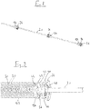
- a roller blind protection cover 10 is shown schematically, which has a roller blind extension 14 that can be wound up on a winding shaft 12.
- a roller blind extension 14 that can be wound up on a winding shaft 12.
- an in Fig. 1 Housing not shown, can be provided, which can be attached as a stationary first component to a stationary element of a machine tool.
- the winding shaft 12 is rotatably mounted on a torsionally rigid axle 20.
- a second, movable component 18 is provided in the form of an angle bar 19, which can be mounted on a movable element of a machine tool (not shown).
- the axis 20 is fixed in a torsionally rigid manner on the housing.
- the roller blind pull-out 14 shields the surroundings from flying chips and possibly cutting fluid, whereby it also provides protection for people present in such a way that they cannot accidentally touch moving parts.
- the movement of the movable element is necessary if, for example, the tool describes a certain travel path.
- roller blind extension 14 While the pull-out of the roller blind extension 14 can be accomplished by the adjustment drive of the machine tool or some other device in which the roller blind protective cover 10 is mounted, precautions must be taken to cause the flexible roller blind extension 14 to be rewound when it moves in the opposite direction.
- a return mechanism is provided in the winding shaft 12, which is designed as a hollow shaft and which works with one or more torsion springs.
- the torsion spring 22 is at an in Figures 2 to 6 embodiment shown with only one torsion spring between the winding shaft 12 and the fixed central axis 20, wherein they are already fully wound up the roller blind is under a certain bias, which increases when the roller blind extension 14 is pulled out.
- Figs. 2 to 4 the fixing of the torsion spring 22 on the winding shaft is illustrated, which has been omitted to make the essential parts visible in the illustration.
- the winding shaft itself is seated in a torsionally rigid manner on an annular shoulder 24 of an annular fastening element 26, which via a roller bearing 28 (see Fig. 4 ) is rotatably mounted on the fixed central axis 20 of the overall device.
- the torsion spring 22 is designed as a helical spring with a plurality of turns 30 made of wire, in particular from Fig. 2 and Fig. 5 It can be clearly seen that the respective end 32 of the helical spring is designed without any special shape, but rather by a simple end face that is created by severing the turn of a longer screw blank. Complex shaping processes can therefore be dispensed with.
- the winding ends 32 are each clamped to a plug 34 which is designed both for torsionally rigid attachment to the winding shaft 12 via the fastening element 26 and for torsionally rigid attachment to the torsionally rigid axle 20. This allows the number of different components to be reduced, but it is of course also possible to individually adapt the stoppers for their respective fastening purpose.
- the plugs 34 have flanges 36 with circular cross-sections and their free ends 38 protrude into the coil springs.
- the flanges 36 each have a cylindrical section 40 with a constant diameter and an adjoining conical section 42 which tapers towards the free end 38 of the flange 34.
- the diameter of the cylindrical section 40 is selected so that the helical spring can easily be put on by hand during assembly; based on the inside diameter of the relaxed torsion spring / helical spring 22, there is a loose fit, possibly also a transition fit for a tighter fit.
- the clamping of the helical spring takes place in the region of the ends 32 with the aid of at least one, in the embodiment shown with the aid of two fastening clamps 44, which are designed as bracket-like sheet metal clamps.
- the two fastening clamps 44 define two fastening points, offset by 180 °, for the winding wire 30 of the helical spring 22. If necessary, even more fastening points with further fastening clamps 44 can be provided, but in order not to impair the deformability of the helical spring 22, these should ideally be distributed over the first turn at the end 32 of the helical spring.
- the sheet metal clamp sits with its two legs 46, 47 pointing radially inward in a radial recess 48.
- the two legs 46, 47 encompass the wire winding 30 of the spring 22 on both sides and are connected to one another in a bow-like manner via webs 50. Aligning through holes (not visible) are formed in the two legs 46, 47, through which a clamping screw 52 protrudes, which is screwed into an axially arranged internal thread (also not visible).
- either the end 32 of the helical spring is first screwed in by slightly turning it relative to the plug 34 between the legs 46, 47 of the fastening clamp 44 radially inside the webs 50 if the fastening clamp 44 has first been preassembled with a loosely screwed in clamping screw 52 is, or — which may be preferred in the case of several fastening points — the fastening clamps 44 are slipped onto the winding 30 of the helical spring 22, which was previously aligned in its angular position with respect to the plug 34. Finally, the clamping screws 52 are then tightened so that the helical spring 22 is clamped in a torsionally rigid manner relative to the plug 34.
- the plug 34 When fixed in a rotationally rigid manner relative to the winding shaft 12, the plug 34 is now connected to the fastening element 26 with the aid of axial screws (not shown), the axial screws protruding through axially through bores in the fastening element 26 and engaging in axial threaded bores 54 in the plug 34.
- the fastening element 26 may have previously been mounted on the bearing 28.
- the stopper 34 is fixed to the torsionally rigid axle 20 at the other end 32 of the helical spring 22 via at least one radially aligned threaded through hole 56 into which a radially arranged clamping screw (not shown) is screwed.
- a radially arranged clamping screw (not shown) is screwed.
- the radially inner shaft end of the clamping screw is clamped against the torsionally rigid axle 20, so that after the subsequent clamping of the helical spring with the plug, the helical spring at the corresponding end is also connected to the torsionally rigid axle 20.
- the plug 34 is first clamped to fix one end of the helical spring on the torsionally rigid axle 20 and then the helical spring is clamped with this plug in the manner described.
- the device shown is wrapped with a roller blind extension 14 and the device is mounted between the relatively movable parts of the machine tool or another device.
- the procedure here can be such that in the zero position with the roller blind completely wound up, a relative rotation between the winding shaft 12 and the torsionally rigid axle 20 is carried out in order to build up a pretensioning of the helical spring.
- the helical spring 22 is arranged in such a way that when the roller blind is pulled out during operation, the spring 22 is pretensioned with a constriction of the turns 30. So that this cannot take place in an uncontrolled manner in the area of the clamping points, the flange 36 is provided to limit the constriction in this area, which prevents the turns 30 of the helical spring 22 from being overstressed in the area of the clamping points due to excessive deformation. This increases the fatigue strength of the roller blind protection cover 10 and it can also be exposed to higher speeds.
- the coil springs 22 can be axially offset to one another (see Fig. 7 ) and / or arranged radially nested (see Figures 8 and 9 ) become.
- the axial arrangement does not result in any additional special features; the two plugs 34 for fixing on the torsionally rigid axle 20 are each further arranged in the center, while the other two plugs 34 are arranged on the outside in the area of the bearings 28 of the winding shaft 12.
- the assembly of the two plugs 34 and 134 is also attached in the same way as before in the simple embodiment to the fastening element 26 in the area of the bearings 28, torsionally rigid with respect to the winding shaft 12 and at the opposite end of the package with at least one radial clamping screw relative to the torsionally rigid axis 20th
Landscapes
- Engineering & Computer Science (AREA)
- General Engineering & Computer Science (AREA)
- Structural Engineering (AREA)
- Mechanical Engineering (AREA)
- Architecture (AREA)
- Civil Engineering (AREA)
- Operating, Guiding And Securing Of Roll- Type Closing Members (AREA)
Claims (15)
- Couvercle de protection de store (10) pour recouvrir un espace de travail variable avec au moins deux composants (18), dont l'espacement varie lors du fonctionnement, dans lequel le couvercle de protection de store (10) présente un arbre d'enroulement associé à un premier des composants et un système d'extraction de store (14) enroulé sur celui-ci, dont l'extrémité libre (16) est associée à l'autre deuxième composant (18), dans lequel l'arbre d'enroulement est réalisé en tant qu'arbre creux et au moins un ressort de torsion (22) réalisé en tant que ressort hélicoïdal est disposé côté intérieur de l'arbre creux, dont une extrémité (32) est fixée avec l'arbre creux rotatif et dont l'autre extrémité (32) est fixée avec un point stationnaire par rapport au premier composant, caractérisé en ce qu'est prévu sur au moins une extrémité (32) du ressort hélicoïdal (22), qui est réalisée en tant que spire découpée à la bonne longueur de la spirale, au moins un emplacement de serrage avec une attache (44), avec laquelle l'extrémité respective est bloquée par rapport à l'arbre d'enroulement (12) ou au premier composant, dans lequel est prévue, dans la zone de l'emplacement de serrage, du côté intérieur du ressort hélicoïdal (22), une bride (36), qui s'étend dans une direction axiale sur plusieurs pas de spire (30) du ressort hélicoïdal (22).
- Couvercle de protection de store selon la revendication 1, caractérisé en ce que la bride (36) se rétrécit de manière étagée ou de manière continue en direction de son extrémité libre (38).
- Couvercle de protection de store selon la revendication 1 ou 2, caractérisé en ce qu'est prévue une adaptation de jeu ou de transition entre le diamètre intérieur le plus grand de la bride (36) et du ressort hélicoïdal (22) dans l'état non mis en tension du ressort hélicoïdal (22).
- Couvercle de protection de store selon l'une quelconque des revendications 1 à 3, caractérisé en ce que l'au moins une attache (44) fait saillie radialement vers l'extérieur de la bride et entoure la spire de fil métallique (30).
- Couvercle de protection de store selon l'une quelconque des revendications précédentes, caractérisé en ce que la bride (36) réalisée de manière cylindrique dans une section (40) se rétrécit de manière conique ou avec un rayon d'incurvation croissant en direction de son extrémité libre (38) en s'éloignant de l'emplacement de serrage.
- Couvercle de protection de store selon l'une quelconque des revendications précédentes, caractérisé en ce qu'est prévu un axe (20) immobile, qui s'étend au centre à travers l'arbre d'enroulement (12).
- Couvercle de protection de store selon l'une quelconque des revendications précédentes, caractérisé en ce que les extrémités de spire (32) sur au moins un emplacement de serrage sont fixées avec respectivement une attache (44) par rapport à l'arbre d'enroulement (12) ou de manière stationnaire par rapport au premier composant sur les deux extrémités du ressort hélicoïdal.
- Couvercle de protection de store selon l'une quelconque des revendications précédentes, caractérisé en ce qu'au moins une partie des emplacements de serrage est réalisée sur un bouchon (34), qui est relié de manière rigide en rotation à l'arbre d'enroulement (12) ou est fixé de manière stationnaire par rapport au premier composant (11), dans lequel la bride (36) est réalisée sur le bouchon (34).
- Couvercle de protection de store selon l'une quelconque des revendications précédentes, caractérisé en ce que sont prévus deux emplacements de serrage ou plus de manière répartie sur la périphérie sur au moins une extrémité du ressort hélicoïdal (22) avec des attaches (44), qui coincent le fil métallique de la spire de ressort hélicoïdal (30).
- Couvercle de protection de store selon l'une quelconque des revendications précédentes, caractérisé en ce que les attaches (44) présentent respectivement une agrafe en métal, qui est coincée contre la spire de fil métallique (30) du ressort hélicoïdal (22) au moyen d'une vis de serrage (52).
- Couvercle de protection de store selon la revendication 10, caractérisé en ce que l'agrafe en métal est réalisée en tant qu'étrier en U, entre les branches (46, 47) duquel est coincée la spire de fil métallique (30).
- Couvercle de protection de store selon la revendication 10 ou 11, caractérisé en ce que les vis de serrage (52) sont disposées côté intérieur radialement des spires (30) dans une direction axiale et les deux branches (46, 47) des agrafes en métal surmontant la spire de fil métallique (30) présentent des alésages pour la vis de serrage (52).
- Couvercle de protection de store selon l'une quelconque des revendications précédentes, caractérisé en ce qu'un axe (20) rigide en rotation est disposé au centre dans l'arbre d'enroulement (12) de sorte que le ressort hélicoïdal (22) se situe entre l'axe (20) et l'arbre d'enroulement (12).
- Couvercle de protection de store selon la revendication 13, caractérisé en ce qu'un premier bouchon (34) est relié par deux emplacements de serrage ou plus de manière rigide en rotation à l'arbre d'enroulement (12) et un deuxième bouchon (34) est relié par deux emplacements de serrage ou plus de manière rigide en rotation à l'axe rigide en rotation.
- Couvercle de protection de store selon l'une quelconque des revendications précédentes, caractérisé en ce qu'il présente un boîtier, qui loge l'arbre d'enroulement (12) et forme le premier composant ou est relié à celui-ci.
Priority Applications (1)
| Application Number | Priority Date | Filing Date | Title |
|---|---|---|---|
| EP19153774.5A EP3686390B1 (fr) | 2019-01-25 | 2019-01-25 | Couvercle de sécurité pour store |
Applications Claiming Priority (1)
| Application Number | Priority Date | Filing Date | Title |
|---|---|---|---|
| EP19153774.5A EP3686390B1 (fr) | 2019-01-25 | 2019-01-25 | Couvercle de sécurité pour store |
Publications (2)
| Publication Number | Publication Date |
|---|---|
| EP3686390A1 EP3686390A1 (fr) | 2020-07-29 |
| EP3686390B1 true EP3686390B1 (fr) | 2021-04-14 |
Family
ID=65241131
Family Applications (1)
| Application Number | Title | Priority Date | Filing Date |
|---|---|---|---|
| EP19153774.5A Active EP3686390B1 (fr) | 2019-01-25 | 2019-01-25 | Couvercle de sécurité pour store |
Country Status (1)
| Country | Link |
|---|---|
| EP (1) | EP3686390B1 (fr) |
Families Citing this family (3)
| Publication number | Priority date | Publication date | Assignee | Title |
|---|---|---|---|---|
| CN112828663A (zh) * | 2020-12-31 | 2021-05-25 | 深圳市格雷特通讯科技有限公司 | 一种数控加工机房降噪防护罩 |
| DE102021125824A1 (de) | 2021-10-05 | 2023-04-06 | Ampack Gmbh | Abdeckvorrichtung für eine Abfüllstation und Abfüllstation mit einer solchen Abdeckvorrichtung |
| CN114850957A (zh) * | 2022-05-24 | 2022-08-05 | 深圳市保佳特机床防护技术有限公司 | 一种可调式伸缩卷帘防护罩 |
Family Cites Families (5)
| Publication number | Priority date | Publication date | Assignee | Title |
|---|---|---|---|---|
| US2696250A (en) * | 1953-08-28 | 1954-12-07 | Michelman Nathan | Rolling door |
| DE102005033275B4 (de) * | 2005-07-15 | 2009-09-10 | Webasto Ag | Wickelwelle für eine Rollovorrichtung |
| DE102012200642A1 (de) * | 2012-01-18 | 2013-07-18 | Hennig Holding Gmbh | Abdeckvorrichtung für Öffnungen, insbesondere für Maschinenöffnungen |
| US20180283091A1 (en) * | 2013-06-03 | 2018-10-04 | Kool Pak LLC | Modular, roll-down airflow control apparatus |
| CN207194781U (zh) * | 2017-09-12 | 2018-04-06 | 川立开发实业有限公司 | 卷式门栏 |
-
2019
- 2019-01-25 EP EP19153774.5A patent/EP3686390B1/fr active Active
Non-Patent Citations (1)
| Title |
|---|
| None * |
Also Published As
| Publication number | Publication date |
|---|---|
| EP3686390A1 (fr) | 2020-07-29 |
Similar Documents
| Publication | Publication Date | Title |
|---|---|---|
| EP1921246B1 (fr) | Dispositif de butée pour le mouvement d'ouverture et de fermeture d'une installation d'obscurcissement | |
| EP3686390B1 (fr) | Couvercle de sécurité pour store | |
| DE2239853C3 (de) | Haltevorrichtung für Außenrückblickspiegel von Kraftfahrzeugen o.dgl | |
| EP2576133B1 (fr) | Tourelle revolver | |
| EP0326607A1 (fr) | Entrainement sans jeu pour mecanisme de reglage d'un microtome | |
| DE2515019C2 (de) | Kolben-Zylinderaggregat für eine Stell- oder Arbeitsvorrichtung | |
| DE102004015825B4 (de) | Gurtaufroller für einen Fahrzeug-Sicherheitsgurt | |
| DE102015207558B4 (de) | Gurtaufroller | |
| DE102008010675A1 (de) | Fangvorrichtung zum Stillsetzen einer Umlenk- oder Wickelwelle | |
| WO2019052921A1 (fr) | Support de panneau et tiroir | |
| EP1555151B2 (fr) | Store à enrouleur pour véhicule | |
| EP1172579A1 (fr) | Ressort torsionnel pour contrepoids, en particuler pour des portes à sections | |
| DE29819740U1 (de) | Federspanner für Schraubenfedern mit wenigstens einem Federteller | |
| DE102020113706B3 (de) | Montagehilfe und Verfahren zur Montage und Demontage von Blockierelementen an einem Federbein | |
| EP0978353A2 (fr) | Meuleuse à carter de protection amovible | |
| DE102010021948A1 (de) | Werkzeugrevolver | |
| EP2163291A1 (fr) | Panier d'appui de filtre | |
| EP1900482B1 (fr) | Appareil de tension pour tendeur à ressort | |
| EP3916190A1 (fr) | Dispositif de verrouillage à ressort | |
| DE102014016308A1 (de) | Gurtaufroller sowie Verfahren zur Steuerung einer Gurtbandauszugskraft in einem Gurtaufroller eines Fahrzeuginsassen-Rückhaltesystems | |
| DE1456115A1 (de) | Selbstsperrende Aufwickelvorrichtung fuer einen Anschnallgurt | |
| DE1781283C3 (de) | Gurtaufroller für Sicherheitsgurte | |
| DE102006011977B4 (de) | Selbstsperrender Gurtaufroller | |
| DE102011005060A1 (de) | Zahnradgetriebe mit Schrägverzahnung | |
| DE10335387B4 (de) | Auf einem Mantelrohr befestigbares Lenksäulenmodul |
Legal Events
| Date | Code | Title | Description |
|---|---|---|---|
| PUAI | Public reference made under article 153(3) epc to a published international application that has entered the european phase |
Free format text: ORIGINAL CODE: 0009012 |
|
| STAA | Information on the status of an ep patent application or granted ep patent |
Free format text: STATUS: THE APPLICATION HAS BEEN PUBLISHED |
|
| AK | Designated contracting states |
Kind code of ref document: A1 Designated state(s): AL AT BE BG CH CY CZ DE DK EE ES FI FR GB GR HR HU IE IS IT LI LT LU LV MC MK MT NL NO PL PT RO RS SE SI SK SM TR |
|
| AX | Request for extension of the european patent |
Extension state: BA ME |
|
| STAA | Information on the status of an ep patent application or granted ep patent |
Free format text: STATUS: REQUEST FOR EXAMINATION WAS MADE |
|
| 17P | Request for examination filed |
Effective date: 20200901 |
|
| RBV | Designated contracting states (corrected) |
Designated state(s): AL AT BE BG CH CY CZ DE DK EE ES FI FR GB GR HR HU IE IS IT LI LT LU LV MC MK MT NL NO PL PT RO RS SE SI SK SM TR |
|
| RIC1 | Information provided on ipc code assigned before grant |
Ipc: F16P 3/02 20060101ALI20201022BHEP Ipc: E06B 9/13 20060101AFI20201022BHEP Ipc: B60J 1/20 20060101ALN20201022BHEP Ipc: E06B 9/60 20060101ALI20201022BHEP Ipc: F16P 1/02 20060101ALI20201022BHEP Ipc: B23Q 11/08 20060101ALN20201022BHEP |
|
| GRAP | Despatch of communication of intention to grant a patent |
Free format text: ORIGINAL CODE: EPIDOSNIGR1 |
|
| STAA | Information on the status of an ep patent application or granted ep patent |
Free format text: STATUS: GRANT OF PATENT IS INTENDED |
|
| INTG | Intention to grant announced |
Effective date: 20201201 |
|
| GRAS | Grant fee paid |
Free format text: ORIGINAL CODE: EPIDOSNIGR3 |
|
| GRAA | (expected) grant |
Free format text: ORIGINAL CODE: 0009210 |
|
| STAA | Information on the status of an ep patent application or granted ep patent |
Free format text: STATUS: THE PATENT HAS BEEN GRANTED |
|
| AK | Designated contracting states |
Kind code of ref document: B1 Designated state(s): AL AT BE BG CH CY CZ DE DK EE ES FI FR GB GR HR HU IE IS IT LI LT LU LV MC MK MT NL NO PL PT RO RS SE SI SK SM TR |
|
| REG | Reference to a national code |
Ref country code: GB Ref legal event code: FG4D Free format text: NOT ENGLISH |
|
| REG | Reference to a national code |
Ref country code: CH Ref legal event code: EP |
|
| REG | Reference to a national code |
Ref country code: DE Ref legal event code: R096 Ref document number: 502019001191 Country of ref document: DE |
|
| REG | Reference to a national code |
Ref country code: IE Ref legal event code: FG4D Free format text: LANGUAGE OF EP DOCUMENT: GERMAN |
|
| REG | Reference to a national code |
Ref country code: AT Ref legal event code: REF Ref document number: 1382526 Country of ref document: AT Kind code of ref document: T Effective date: 20210515 |
|
| RAP4 | Party data changed (patent owner data changed or rights of a patent transferred) |
Owner name: HEMA MASCHINEN- UND APPARATESCHUTZ GMBH |
|
| REG | Reference to a national code |
Ref country code: LT Ref legal event code: MG9D |
|
| REG | Reference to a national code |
Ref country code: NL Ref legal event code: MP Effective date: 20210414 |
|
| PG25 | Lapsed in a contracting state [announced via postgrant information from national office to epo] |
Ref country code: HR Free format text: LAPSE BECAUSE OF FAILURE TO SUBMIT A TRANSLATION OF THE DESCRIPTION OR TO PAY THE FEE WITHIN THE PRESCRIBED TIME-LIMIT Effective date: 20210414 Ref country code: LT Free format text: LAPSE BECAUSE OF FAILURE TO SUBMIT A TRANSLATION OF THE DESCRIPTION OR TO PAY THE FEE WITHIN THE PRESCRIBED TIME-LIMIT Effective date: 20210414 Ref country code: FI Free format text: LAPSE BECAUSE OF FAILURE TO SUBMIT A TRANSLATION OF THE DESCRIPTION OR TO PAY THE FEE WITHIN THE PRESCRIBED TIME-LIMIT Effective date: 20210414 Ref country code: BG Free format text: LAPSE BECAUSE OF FAILURE TO SUBMIT A TRANSLATION OF THE DESCRIPTION OR TO PAY THE FEE WITHIN THE PRESCRIBED TIME-LIMIT Effective date: 20210714 Ref country code: NL Free format text: LAPSE BECAUSE OF FAILURE TO SUBMIT A TRANSLATION OF THE DESCRIPTION OR TO PAY THE FEE WITHIN THE PRESCRIBED TIME-LIMIT Effective date: 20210414 |
|
| PG25 | Lapsed in a contracting state [announced via postgrant information from national office to epo] |
Ref country code: IS Free format text: LAPSE BECAUSE OF FAILURE TO SUBMIT A TRANSLATION OF THE DESCRIPTION OR TO PAY THE FEE WITHIN THE PRESCRIBED TIME-LIMIT Effective date: 20210814 Ref country code: GR Free format text: LAPSE BECAUSE OF FAILURE TO SUBMIT A TRANSLATION OF THE DESCRIPTION OR TO PAY THE FEE WITHIN THE PRESCRIBED TIME-LIMIT Effective date: 20210715 Ref country code: RS Free format text: LAPSE BECAUSE OF FAILURE TO SUBMIT A TRANSLATION OF THE DESCRIPTION OR TO PAY THE FEE WITHIN THE PRESCRIBED TIME-LIMIT Effective date: 20210414 Ref country code: PT Free format text: LAPSE BECAUSE OF FAILURE TO SUBMIT A TRANSLATION OF THE DESCRIPTION OR TO PAY THE FEE WITHIN THE PRESCRIBED TIME-LIMIT Effective date: 20210816 Ref country code: SE Free format text: LAPSE BECAUSE OF FAILURE TO SUBMIT A TRANSLATION OF THE DESCRIPTION OR TO PAY THE FEE WITHIN THE PRESCRIBED TIME-LIMIT Effective date: 20210414 Ref country code: LV Free format text: LAPSE BECAUSE OF FAILURE TO SUBMIT A TRANSLATION OF THE DESCRIPTION OR TO PAY THE FEE WITHIN THE PRESCRIBED TIME-LIMIT Effective date: 20210414 Ref country code: NO Free format text: LAPSE BECAUSE OF FAILURE TO SUBMIT A TRANSLATION OF THE DESCRIPTION OR TO PAY THE FEE WITHIN THE PRESCRIBED TIME-LIMIT Effective date: 20210714 Ref country code: PL Free format text: LAPSE BECAUSE OF FAILURE TO SUBMIT A TRANSLATION OF THE DESCRIPTION OR TO PAY THE FEE WITHIN THE PRESCRIBED TIME-LIMIT Effective date: 20210414 |
|
| REG | Reference to a national code |
Ref country code: DE Ref legal event code: R097 Ref document number: 502019001191 Country of ref document: DE |
|
| PG25 | Lapsed in a contracting state [announced via postgrant information from national office to epo] |
Ref country code: ES Free format text: LAPSE BECAUSE OF FAILURE TO SUBMIT A TRANSLATION OF THE DESCRIPTION OR TO PAY THE FEE WITHIN THE PRESCRIBED TIME-LIMIT Effective date: 20210414 Ref country code: EE Free format text: LAPSE BECAUSE OF FAILURE TO SUBMIT A TRANSLATION OF THE DESCRIPTION OR TO PAY THE FEE WITHIN THE PRESCRIBED TIME-LIMIT Effective date: 20210414 Ref country code: SK Free format text: LAPSE BECAUSE OF FAILURE TO SUBMIT A TRANSLATION OF THE DESCRIPTION OR TO PAY THE FEE WITHIN THE PRESCRIBED TIME-LIMIT Effective date: 20210414 Ref country code: SM Free format text: LAPSE BECAUSE OF FAILURE TO SUBMIT A TRANSLATION OF THE DESCRIPTION OR TO PAY THE FEE WITHIN THE PRESCRIBED TIME-LIMIT Effective date: 20210414 Ref country code: RO Free format text: LAPSE BECAUSE OF FAILURE TO SUBMIT A TRANSLATION OF THE DESCRIPTION OR TO PAY THE FEE WITHIN THE PRESCRIBED TIME-LIMIT Effective date: 20210414 Ref country code: CZ Free format text: LAPSE BECAUSE OF FAILURE TO SUBMIT A TRANSLATION OF THE DESCRIPTION OR TO PAY THE FEE WITHIN THE PRESCRIBED TIME-LIMIT Effective date: 20210414 Ref country code: DK Free format text: LAPSE BECAUSE OF FAILURE TO SUBMIT A TRANSLATION OF THE DESCRIPTION OR TO PAY THE FEE WITHIN THE PRESCRIBED TIME-LIMIT Effective date: 20210414 |
|
| PLBE | No opposition filed within time limit |
Free format text: ORIGINAL CODE: 0009261 |
|
| STAA | Information on the status of an ep patent application or granted ep patent |
Free format text: STATUS: NO OPPOSITION FILED WITHIN TIME LIMIT |
|
| 26N | No opposition filed |
Effective date: 20220117 |
|
| PG25 | Lapsed in a contracting state [announced via postgrant information from national office to epo] |
Ref country code: IS Free format text: LAPSE BECAUSE OF FAILURE TO SUBMIT A TRANSLATION OF THE DESCRIPTION OR TO PAY THE FEE WITHIN THE PRESCRIBED TIME-LIMIT Effective date: 20210814 Ref country code: AL Free format text: LAPSE BECAUSE OF FAILURE TO SUBMIT A TRANSLATION OF THE DESCRIPTION OR TO PAY THE FEE WITHIN THE PRESCRIBED TIME-LIMIT Effective date: 20210414 |
|
| PG25 | Lapsed in a contracting state [announced via postgrant information from national office to epo] |
Ref country code: MC Free format text: LAPSE BECAUSE OF FAILURE TO SUBMIT A TRANSLATION OF THE DESCRIPTION OR TO PAY THE FEE WITHIN THE PRESCRIBED TIME-LIMIT Effective date: 20210414 |
|
| REG | Reference to a national code |
Ref country code: CH Ref legal event code: PL |
|
| REG | Reference to a national code |
Ref country code: BE Ref legal event code: MM Effective date: 20220131 |
|
| PG25 | Lapsed in a contracting state [announced via postgrant information from national office to epo] |
Ref country code: LU Free format text: LAPSE BECAUSE OF NON-PAYMENT OF DUE FEES Effective date: 20220125 |
|
| PG25 | Lapsed in a contracting state [announced via postgrant information from national office to epo] |
Ref country code: BE Free format text: LAPSE BECAUSE OF NON-PAYMENT OF DUE FEES Effective date: 20220131 |
|
| PG25 | Lapsed in a contracting state [announced via postgrant information from national office to epo] |
Ref country code: LI Free format text: LAPSE BECAUSE OF NON-PAYMENT OF DUE FEES Effective date: 20220131 Ref country code: CH Free format text: LAPSE BECAUSE OF NON-PAYMENT OF DUE FEES Effective date: 20220131 |
|
| PG25 | Lapsed in a contracting state [announced via postgrant information from national office to epo] |
Ref country code: IE Free format text: LAPSE BECAUSE OF NON-PAYMENT OF DUE FEES Effective date: 20220125 |
|
| PG25 | Lapsed in a contracting state [announced via postgrant information from national office to epo] |
Ref country code: MK Free format text: LAPSE BECAUSE OF FAILURE TO SUBMIT A TRANSLATION OF THE DESCRIPTION OR TO PAY THE FEE WITHIN THE PRESCRIBED TIME-LIMIT Effective date: 20210414 Ref country code: CY Free format text: LAPSE BECAUSE OF FAILURE TO SUBMIT A TRANSLATION OF THE DESCRIPTION OR TO PAY THE FEE WITHIN THE PRESCRIBED TIME-LIMIT Effective date: 20210414 |
|
| PG25 | Lapsed in a contracting state [announced via postgrant information from national office to epo] |
Ref country code: HU Free format text: LAPSE BECAUSE OF FAILURE TO SUBMIT A TRANSLATION OF THE DESCRIPTION OR TO PAY THE FEE WITHIN THE PRESCRIBED TIME-LIMIT; INVALID AB INITIO Effective date: 20190125 |
|
| PG25 | Lapsed in a contracting state [announced via postgrant information from national office to epo] |
Ref country code: MT Free format text: LAPSE BECAUSE OF FAILURE TO SUBMIT A TRANSLATION OF THE DESCRIPTION OR TO PAY THE FEE WITHIN THE PRESCRIBED TIME-LIMIT Effective date: 20210414 |
|
| REG | Reference to a national code |
Ref country code: AT Ref legal event code: MM01 Ref document number: 1382526 Country of ref document: AT Kind code of ref document: T Effective date: 20240125 |
|
| PG25 | Lapsed in a contracting state [announced via postgrant information from national office to epo] |
Ref country code: AT Free format text: LAPSE BECAUSE OF NON-PAYMENT OF DUE FEES Effective date: 20240125 |
|
| PG25 | Lapsed in a contracting state [announced via postgrant information from national office to epo] |
Ref country code: TR Free format text: LAPSE BECAUSE OF FAILURE TO SUBMIT A TRANSLATION OF THE DESCRIPTION OR TO PAY THE FEE WITHIN THE PRESCRIBED TIME-LIMIT Effective date: 20210414 |
|
| REG | Reference to a national code |
Ref country code: DE Ref legal event code: R082 Ref document number: 502019001191 Country of ref document: DE Representative=s name: BOEHMERT & BOEHMERT ANWALTSPARTNERSCHAFT MBB -, DE |
|
| PGFP | Annual fee paid to national office [announced via postgrant information from national office to epo] |
Ref country code: GB Payment date: 20260119 Year of fee payment: 8 |
|
| PGFP | Annual fee paid to national office [announced via postgrant information from national office to epo] |
Ref country code: DE Payment date: 20251126 Year of fee payment: 8 |
|
| PGFP | Annual fee paid to national office [announced via postgrant information from national office to epo] |
Ref country code: AT Payment date: 20260410 Year of fee payment: 5 |
|
| PGFP | Annual fee paid to national office [announced via postgrant information from national office to epo] |
Ref country code: IT Payment date: 20260127 Year of fee payment: 8 |
|
| PGFP | Annual fee paid to national office [announced via postgrant information from national office to epo] |
Ref country code: FR Payment date: 20260120 Year of fee payment: 8 |