EP3688260B1 - Ferrure pouvant être enclenchée dans la position de basculement et pouvant toutefois être déplacée facilement lors de la fermeture par glissement pour une fenêtre ou une porte - Google Patents
Ferrure pouvant être enclenchée dans la position de basculement et pouvant toutefois être déplacée facilement lors de la fermeture par glissement pour une fenêtre ou une porte Download PDFInfo
- Publication number
- EP3688260B1 EP3688260B1 EP18782658.1A EP18782658A EP3688260B1 EP 3688260 B1 EP3688260 B1 EP 3688260B1 EP 18782658 A EP18782658 A EP 18782658A EP 3688260 B1 EP3688260 B1 EP 3688260B1
- Authority
- EP
- European Patent Office
- Prior art keywords
- fitting
- closed position
- open position
- bypass
- spring element
- Prior art date
- Legal status (The legal status is an assumption and is not a legal conclusion. Google has not performed a legal analysis and makes no representation as to the accuracy of the status listed.)
- Active
Links
Images



Classifications
-
- E—FIXED CONSTRUCTIONS
- E05—LOCKS; KEYS; WINDOW OR DOOR FITTINGS; SAFES
- E05D—HINGES OR SUSPENSION DEVICES FOR DOORS, WINDOWS OR WINGS
- E05D15/00—Suspension arrangements for wings
- E05D15/06—Suspension arrangements for wings for wings sliding horizontally more or less in their own plane
- E05D15/10—Suspension arrangements for wings for wings sliding horizontally more or less in their own plane movable out of one plane into a second parallel plane
- E05D15/1005—Suspension arrangements for wings for wings sliding horizontally more or less in their own plane movable out of one plane into a second parallel plane the wing being supported on arms movable in horizontal planes
- E05D15/1013—Suspension arrangements for wings for wings sliding horizontally more or less in their own plane movable out of one plane into a second parallel plane the wing being supported on arms movable in horizontal planes specially adapted for windows
- E05D15/1015—Suspension arrangements for wings for wings sliding horizontally more or less in their own plane movable out of one plane into a second parallel plane the wing being supported on arms movable in horizontal planes specially adapted for windows with an intermediate tilt position
-
- E—FIXED CONSTRUCTIONS
- E05—LOCKS; KEYS; WINDOW OR DOOR FITTINGS; SAFES
- E05Y—INDEXING SCHEME ASSOCIATED WITH SUBCLASSES E05D AND E05F, RELATING TO CONSTRUCTION ELEMENTS, ELECTRIC CONTROL, POWER SUPPLY, POWER SIGNAL OR TRANSMISSION, USER INTERFACES, MOUNTING OR COUPLING, DETAILS, ACCESSORIES, AUXILIARY OPERATIONS NOT OTHERWISE PROVIDED FOR, APPLICATION THEREOF
- E05Y2800/00—Details, accessories and auxiliary operations not otherwise provided for
- E05Y2800/74—Specific positions
- E05Y2800/75—Specific positions intermediate
-
- E—FIXED CONSTRUCTIONS
- E05—LOCKS; KEYS; WINDOW OR DOOR FITTINGS; SAFES
- E05Y—INDEXING SCHEME ASSOCIATED WITH SUBCLASSES E05D AND E05F, RELATING TO CONSTRUCTION ELEMENTS, ELECTRIC CONTROL, POWER SUPPLY, POWER SIGNAL OR TRANSMISSION, USER INTERFACES, MOUNTING OR COUPLING, DETAILS, ACCESSORIES, AUXILIARY OPERATIONS NOT OTHERWISE PROVIDED FOR, APPLICATION THEREOF
- E05Y2900/00—Application of doors, windows, wings or fittings thereof
- E05Y2900/10—Application of doors, windows, wings or fittings thereof for buildings or parts thereof
- E05Y2900/13—Type of wing
- E05Y2900/148—Windows
Definitions
- the invention relates to a fitting for connecting a wing to a fixed frame of a window or door on one side.
- the invention also relates to a window or a door with such a fitting.
- the invention also relates to a method for opening and closing a sash of a window or a door by means of a fitting.
- sashes of windows or doors tend to slam shut due to drafts and/or due to an unfavorably located center of gravity of the sash.
- the sash can tend to close in the tilted position if the glazing is far to the outside.
- fittings In order to prevent the sash from falling or slamming in the tilted position, fittings have become known that lock the sash in the tilted position.
- Appropriate fittings and locking devices for tilt and turn windows are from EP 2 824 264 A1 , the DE 10 2016 202377 A1 , the DE 80 23 717 U1 , the DE 75 20 486 U1 , the DE 36 19 682 A1 , the DE 102 22 464 A1 and the DE 39 04 210 A1 known.
- the EP 0 231 498 A2 a fitting for a wing that can be tilted and displaced relative to the fixed frame, the fitting having a latching device.
- the object of the present invention is therefore to provide a fitting for connecting a tiltable sash which can be moved when parked away from the fixed frame and which allows both latching in the tilted position and easy closing from the parked position.
- the object of the invention is also to provide a window or a door with such a fitting. Furthermore, it is the object of the invention to provide a corresponding method for opening and closing a sash.
- the fitting has a spring element with a spring element section, a latching element and a bypass element. In the tilted position, the spring element section engages behind the latching element and thereby enables latching of the wing.
- the fitting is designed in such a way that when moving from the open position to the closed position by direct or indirect actuation by the bypass element, it engages at least less strongly than in the tilted position, so that the sash can be easily moved from its open position to the closed position.
- the bypass element can directly or indirectly redirect the spring element section in order to reduce or cancel the latching of the spring element section provided for the tilted position on the latching element in the closing movement of the fitting from the open position into the closed position.
- the fitting enables the wing to be locked in the tilted position without a user having to forego the possibility of conveniently closing the wing from the parked position.
- the terms "closed position”, “tilted position” and “open position” are analogous to the fitting and the wing used.
- the wing is usually arranged on the fixed frame via additional fittings in such a way that the wing can be moved from the closed position either into its tilted position or into its open position.
- the wing is usually designed in such a way that the plane of the wing is moved parallel to the main frame plane of the fixed frame during the movement from the closed position of the wing to the open position of the wing.
- the fitting according to the invention In its open position, at least in the area of the fitting, the sash is placed further away from the fixed frame than in its tilted position.
- the fitting according to the invention is moved from the closed position to the open position via the tilted position of the fitting according to the invention during the movement of the wing; at the time when the fitting according to the invention is in the tilted position, the wing is not usually in its tilted position, but it is just on the way to its parallel parked open position of the wing.
- the wing when the fitting according to the invention is in the tilted position, the wing is either actually in its tilted position or it is on the way to its more open open position.
- bottom refers to the mounted condition of the hardware on a window or door.
- the "hysteresis" of the fitting according to the invention ie a movement of the fitting from the closed position to the open position, which differs from the movement from the open position to the closed position, can be implemented mechanically in different ways. Variants are described below that have a particularly simple design and can therefore be produced cost-effectively.
- the locking element and the bypass element can be moved towards one another, in particular can be displaced towards one another.
- the locking element and the bypass element can preferably be moved towards one another until they come into mutual contact and/or both can be moved together.
- the spring element section is supported in the open position on the
- the spring element section can thereby be moved towards the latching element during movement from the open position into the closed position, so that the spring element section engages less or not behind the latching element during the transition from the open position to the closed position.
- the latching element is part of a control element of the fitting or is arranged on the control element, in particular rigidly.
- the control element is preferably in the form of a slide.
- the control element can be slidably arranged on a rail of the fitting.
- the control element can be positively controlled, i.e. the control element can be designed to perform a forced movement as a result of the opening and closing movement of the fitting.
- the fitting has a damper and/or a spring in order to be able to move the sash comfortably.
- the damper and/or the spring is/are preferably one-ended arranged or formed directly or indirectly on the control.
- the damper and/or the spring can be arranged on a rail of the fitting.
- the control element is forced to be controlled by a control arm, which is part of a scissor stay of the fitting.
- the control arm is directly or indirectly articulated to a deployment arm of the deployment scissor.
- the bypass element can be embodied in the form of a slide and can be moved, in particular slidably, relative to a rail of the fitting. Except for the influence of the spring element section, the bypass element can be freely movable, in particular displaceable, between contact points of the fitting.
- the contact points of the fitting are preferably formed by a stop of the, in particular displaceable, control element and the latching element.
- the bypass element can have a first projection which is at least partially gripped behind by the spring element section when the fitting is at least partially moved from the open position to the closed position.
- bypass element can have a second projection for reasons of symmetry in order to avoid incorrect assembly of the bypass element.
- the latching element and/or the bypass element has/have a flat section for supporting the spring element section.
- the flat section or the flat sections enables/enable an easy displacement of the spring element section on the latching element or on the bypass element.
- the slight displacement of the spring element section relative to the bypass element is preferably limited by at least one, in particular both, of the projections described above.
- the assembly of the bypass element is made easier if the bypass element is mirror-symmetrical.
- the mirror plane preferably extends perpendicular to the longitudinal axis of the bypass element.
- the bypass element is preferably arranged to be easily displaceable relative to the control element and/or to a rail of the fitting.
- the bypass element can be locked in a groove in a rail of the fitting.
- the bypass element can be guided in a groove of a rail of the fitting and locked in a groove of the control element.
- the control element can be arranged or formed on the rail of the fitting.
- the control element is preferably designed to be movable, in particular displaceable, relative to the rail.
- the spring element can be arranged or formed on the rail of the fitting.
- the spring element is preferably designed in the form of a spring arm which is fastened to the rail.
- the fitting can have at least one slider in order to move the leaf in the open position, in particular parked parallel to the fixed frame.
- the object of the invention is further achieved by a window or a door with a fixed frame, a leaf movable relative to the fixed frame and a previously described fitting for one-sided, in particular top-side, connection of the leaf to the fixed frame.
- the fitting for carrying out the method according to the invention has a bypass element and a spring element section of a spring element, with the bypass element and a latching element being moved towards one another, in particular pushed towards one another, when the fitting is moved from the open position to the closed position, so that the movement of the spring element section the latching element is facilitated when the fitting is closed further.
- the latching element preferably moves towards the bypass element and then moves, in particular shifts, the bypass element.
- the spring element is preferably arranged in a stationary manner.
- the spring element section is preferably moved, in particular pushed, onto the bypass element when the fitting is moved from the tilted position into the open position.
- the bypass element can be displaced by the spring element section from the latching element when the fitting is moved from the closed position into the tilted position.
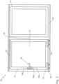
- figure 1 12 shows a door 10 having a fixed frame 12 and a leaf 14.
- the leaf 14 is supported on its underside by a carriage assembly 16.
- FIG. When the wing 14 is off the fixed frame 12, it can be moved in the direction of an arrow 18 . The displacement of the wing 14 takes place in particular parallel to the fixed frame 12 parked.
- the carriage arrangement 16 has a first carriage 20 and in particular a second carriage 22 .
- the carriages 20, 22 run on a rail 24.
- the wing 14 has a handle 26 .
- the handle 26 is movable to a first handle position 26a in which the leaf 14 is in the closed position. In the closed position, the leaf 14 is firmly locked to the fixed frame 12. If the handle 26 is pivoted into a second handle position 26b , the wing 14 can be turned off from the fixed frame 12 and moved in the direction of the arrow 18. The wing 14 is then in an open position. If, on the other hand, the handle 26 is pivoted from the first handle position 26a into a third handle position 26c , the leaf 14 cannot be set down from the fixed frame 12 on one side, here on its underside.
- the wing 14 is then however on one side, here with its upper side, away from the fixed frame 12, so that a user can move the wing 14 into a tilted position.
- This side of the wing 14, here the upper side of the wing 14, is placed less far from the fixed frame 12 in the tilted position than in the open position 28
- the fitting 28 is also in the closed position. If the leaf 14 is in the closed position, the fitting 28 is also in the tilted position. If the leaf 14 is moved from the closed position to the open position, the fitting 28 passes the tilted position. At this point in time, however, the wing 14 is not in its tilted position since it is parked parallel to the fixed frame 12. To be more precise, the leaf 14 is only in the tilted position in the area of the fitting 28, but not all of it, since it is also parked by the fixed frame 12 on its side opposite the fitting 28. The closing of the wing 14 from the open position to the closed position also takes place in the plane of the wing 14 parallel to the main frame plane of the fixed frame 12.
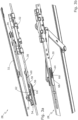
- figure 2 12 shows the majority of the fitting 28.
- the fitting 28 has a first rail 30 and a second rail 32.
- the first rail 30 is for moving the wing 14 (see figure 1 ) movable, slidable here, arranged on the fixed frame 12, which in figure 2 only partially shown for reasons of clarity.
- the second rail 32 is on one side, here on the upper side, of the wing 14 (see figure 1 ) fixed.
- the fitting 28 has a first deployment arm 34 and in particular a second Extension arm 36 on.
- a first control arm 38 is provided for guiding the first deployment arm 34 .
- a second control arm 40 is provided for guiding the second deployment arm 36 .
- the first opening arm 34 together with the first control arm 38 forms a first opening scissor 42.
- the second opening arm 36 forms a second opening scissor 44 with the second control arm 40.
- the second control arm 40 is also designed to latch the first fitting 28 in the open position.
- a first control pin 46 engages in a locking recess 48 which is preferably formed in the second control arm 40 . If the first control bolt 46 is latched in the latching recess 48, this latching can only take place by actuating the second control arm 40, here by actuating a second control bolt 50 .
- the fitting 28 is not in the open position, but rather, as in figure 2 shown, in the tilted position, the first control pin 46 does not latch in the latching recess 48. Because the fitting 28 is in the in figure 2 tilted position shown less open than in the open position. The second scissor stay 44 thus does not prevent the sash 14 from slamming shut (see figure 1 ) from the tilted position to the closed position.
- the wing 14 (see figure 1 ) may tend to move to the closed position due to an unfavorable center of gravity and/or drafts.
- a latching device for the tilted position is provided according to the invention (the fitting 28 is in Figure 4b shown in this rest-tilt position). It should be noted here that a conventional latching of the fitting 28 in the tilted position would impede or make it more difficult to comfortably close the fitting 28 from the open position to the closed position. It is therefore the object of the invention to provide a fitting 28 which on the one hand locks in the tilted position and on the other hand nevertheless allows the fitting to be closed gently from the open position to the closed position.
- Figure 3a shows a partial view of the fitting 28 in the area of the first scissor stay 42 (see figure 2 ).
- the first rail 30, the first control arm 38, the first deployment arm 34 and the second rail 32 are preferably arranged vertically offset from one another.
- Fixed to the first rail 30 is a slider 52 to facilitate sliding of the fitting relative to the fixed frame 12 (see Fig figure 1 ) to facilitate.
- the first control arm 38 is arranged directly or indirectly on a control element 54 .
- the control element 54 is arranged on the first rail 30 so that it can move, in this case it can be displaced.
- Movement of the first deployment arm 34 causes movement of the first control arm 38, which in turn moves the control element 54 relative to the first rail 30.
- a damper and/or a spring (not shown) can be arranged or formed on the control element 54 at one end. At the other end, the damper and/or the spring is/are preferably arranged or formed on the first rail 30 . A movement of the first control arm 38 thus also causes the damper or the spring to be actuated.
- the control element 54 has a cantilever 56 .
- a latching element 58 is provided at the free end of the cantilever 56 .
- the control element 54 can be designed in several parts. Preferably, the control element 54, as in Figure 3a shown, ie integrally formed with the locking element 58 in one piece.
- a spring element 60 is arranged fixedly on the first rail 30 .
- the spring element 60 is in the form of a spring arm.
- the spring element 60 has a spring element section 62 in the area of its free end.
- the spring element section 62 is supported in the in Figure 3a shown open position of the fitting 28 on a bypass element 64 from.
- Figure 3b shows the fitting 28 according to FIG Figure 3a in another view.
- Figure 3b clarifies that the bypass element 64 is provided with at least one latching section 66, preferably with two latching sections (as in Figure 3b shown), is slidably disposed in a groove 68 of the first rail 30.
- Figure 4a shows the fitting 28 in the closed position.
- the spring element section 62 does not engage behind the latching element 58 .
- the spring element section 62 is preferably at a distance from the latching element 58 in the closed position .
- Figure 4b shows the fitting 28 in the tilted position.
- the spring element section 62 has moved during the transition from the closed position (see Figure 4a ) moves past the latching element 58 into the tilted position.
- spring element section 62 has latching element 58 run over. If the bypass element 64 rests against the latch element 58 , the spring element section 62 displaces the bypass element 64 after the latch element 58 has moved past the spring element section relative to the spring element section 62 .
- the spring element section 62 now engages behind the latching element 58. This engagement secures the wing 14 (see FIG figure 1 ) against an unwanted return movement into the closed position, ie against slamming.
- bypass element 64 abuts against the stop 70 of the control element 54 .
- the spring element section 62 can thus no longer displace the bypass element 64 .
- a gap S remains between the latching element 58 and the bypass element 64, in which the spring element section 62 can enter in the tilted position.
- Figure 4c shows the fitting 28 in the open position.
- the to Figure 4b described resistance to further opening of the fitting 28 is easily overcome.
- the resistance of the spring element section 62 in relation to the latching element 58 or the bypass element 64 can be adjusted by a corresponding configuration of the bevels of the latching element 58, the spring element section 62 or the bypass element 64.
- the bypass member 64 includes a first protrusion 72 and a second protrusion 74 .
- the spring element section 62 can be moved between the projections 72, 74, here it can be displaced. Between the projections 72, 74, the bypass element 64 is flat. This facilitates the displaceability of the spring element section 62 relative to the bypass element 64. For reasons of symmetry, the second projection 74 prevents incorrect installation of the bypass element 64.
- the function of the first projection 72 is explained below Figure 4d explained.
- Figure 4d shows the fitting 28 moving from the open position (see Fig Figure 4c ) to the closed position (see Figure 4f ). From a comparison of figures 4c and 4d it can be seen that the control element 54 moves away from a fastening point 76 of the spring element 60 when the fitting 28 is closed. Here, the latching element 58 comes into contact with the bypass element 64. As a result, the bypass element 64 is also moved away from the fastening point 76 of the spring element 60. The first projection 72 prevents the spring element section 62 from easily slipping off the bypass element 64 and reaching behind the latching element 58 . The gap S (see Figure 4b ) was moved from the open position (see Figure 4c ) to the closed position (see Figure 4f ) at least reduced, in particular fully closed (as in Figure 4d shown).
- Figure 4e shows the fitting 28 during the further closing process. From a synopsis of Figures 4d and 4e it can be seen that the spring element section 62 reaches the latching element 58 directly from the bypass element 64 , in particular reaches a plane of the latching element 58 without reaching behind the latching element 58 . The fitting 28 can thus be moved from the open position (see Figure 4c ) without latching effect in the closed position (see Figure 4f ) reach.
- Figure 4f shows the fitting 28 in the closed position.
- Figure 4f makes it clear that the bypass element 64 is mirror-symmetrical to a mirror plane 78 . This facilitates the assembly of the bypass element 64 on the first rail 30, since an installer does not have to pay as much attention to the orientation of the bypass element 64 when installing it.
- the upper level of a plate-shaped section 80 of the bypass element 64 is aligned with the upper level of a plate-shaped section 82 of the latching element 58. As a result, the closing movement of the fitting 28 can take place particularly evenly.
- the fitting 28 takes a maximum of in the Figures 4a and 4b shown positions.
- the spring element section 62 engages behind in the tilted position (see Figure 4b ) the locking element 58.
- the invention relates in summary to a fitting 28 for connecting a displaceable and tiltable leaf 14 to a fixed frame 12.
- the fitting 28 preferably has a bypass element 64 that is arranged or designed to be movable.
- the fitting 28 is designed to set the wing 14 further away from the fixed frame 12 in the open position, in which the wing 14 can be displaced, than in the tilted position in which the fitting 28 is latched.
- the latching in the tilted position preferably takes place by reaching behind, in particular reaching over, a latching element 58 of the fitting 28.
- a spring element section 62 of a spring element 60 of the fitting 28 can be supported on the bypass element 64 in the open position.
- the bypass element 64 preferably becomes the latching element 58 during the transition from the open position to the closed position moved to reduce a gap S between the bypass member 64 and the latching member 58.
- the reduced gap S causes at least a reduction in the grip of the latching element 58 from behind by the spring element section 62.
- the latching strength of the fitting 28 is thereby at least reduced.
Landscapes
- Engineering & Computer Science (AREA)
- Mechanical Engineering (AREA)
- Closing And Opening Devices For Wings, And Checks For Wings (AREA)
- Wing Frames And Configurations (AREA)
Claims (11)
- Ferrure (28) dévolue au rattachement unilatéral d'un vantail (14) à un cadre fixe (12) d'une fenêtre ou d'une porte (10), laquelle ferrure (28) comprend :i) un élément élastique (60) muni d'un tronçon (62) ;ii) un élément d'encliquetage (58) ;iii) un élément de contournement (64) ;ladite ferrure (28) rendant possibles, en succession, les positions suivantes :a) une position de fermeture dans laquelle la ferrure (28) est fermée ;b) une position de basculement dans laquelle ladite ferrure (28) est ouverte, le tronçon (62) de l'élément élastique emprisonnant par-derrière l'élément d'encliquetage (58), dans ladite position de basculement, de telle sorte que ladite ferrure (28) s'encliquette, au moins en opposition à un mouvement rétrograde vers la position de fermeture, afin d'empêcher un claquement du vantail ;c) une position d'ouverture dans laquelle ladite ferrure (28) est ouverte davantage que dans la position de basculement, ladite position d'ouverture rendant possible un déplacement du vantail ;d) la position de fermeture ;sachant que, lors du mouvement de la position d'ouverture à la position de fermeture, le tronçon (62) de l'élément élastique ne s'encliquette pas sur l'élément d'encliquetage, ou s'encliquette moins fortement que dans la position de basculement, sous l'effet d'une action directe ou indirecte de l'élément de contournement (64), de manière à faciliter le mouvement du vantail (14) de ladite position d'ouverture à ladite position de fermeture, sachant que, lors du mouvement de la ferrure (28) de la position d'ouverture à la position de fermeture, ledit tronçon (62) de l'élément élastique prend appui sur ledit élément de contournement (64) jusqu'à ce que ledit tronçon (62) de l'élément élastique transite vers l'élément d'encliquetage (58), lequel élément d'encliquetage (58) est disposé ou façonné sur un élément de commande (54) de la ferrure (28), ledit élément de commande étant mû avec pilotage forcé sous l'action de la ferrure (28), lors de l'ouverture et de la fermeture de ladite ferrure (28), laquelle ferrure (28) est dotée d'un croisillon articulé déployable (42) comportant un bras extensible (34) et un bras de commande (38), ledit bras de commande (38) étant articulé directement ou indirectement sur ledit bras extensible (34), à une extrémité, et directement ou indirectement sur l'élément de commande (54) à l'autre extrémité, en vue du pilotage forcé dudit élément de commande (54), sachant que, lors de la fermeture de ladite ferrure (28), ledit élément de contournement (64) et ledit élément d'encliquetage (58) sont mus en direction l'un de l'autre de la position d'ouverture à la position de fermeture, jusqu'à la venue en applique mutuelle, de manière à faciliter la transition dudit tronçon (62) de l'élément élastique vers ledit élément d'encliquetage (58).
- Ferrure selon la revendication 1, dans laquelle l'élément de contournement (64) peut être mû librement, en particulier déplacé librement entre une butée (70) de l'élément de commande (54) et l'élément d'encliquetage (58), à l'exception d'un guidage par l'intermédiaire du tronçon (62) de l'élément élastique, lequel élément de contournement (64) est préférentiellement agencé, avec faculté de déplacement, sur une glissière (30) de ladite ferrure (28).
- Ferrure selon l'une des revendications précédentes, dans laquelle l'élément de contournement (64) est muni d'une première butée (72) au moins partiellement emprisonnée par-derrière, par le tronçon (62) de l'élément élastique, lors du mouvement au moins partiel de ladite ferrure (28) de la position d'ouverture à la position de fermeture, de façon telle que ledit tronçon (62) de l'élément élastique ne ripe pas à l'écart dudit élément de contournement.
- Ferrure selon la revendication 3, dans laquelle l'élément de contournement (64) est pourvu d'une seconde butée (74) réalisée avec symétrie spéculaire par rapport à la première butée (72).
- Ferrure selon l'une des revendications précédentes, dans laquelle l'élément d'encliquetage (58) et/ou l'élément de contournement (64) comporte(nt) une région aplatie (80, 82) sur laquelle le tronçon (62) de l'élément élastique peut prendre appui.
- Ferrure selon l'une des revendications précédentes, dans laquelle l'élément élastique (60) est réalisé sous la forme d'un bras de ressort fixé à une glissière (30) de ladite ferrure (28).
- Ferrure selon l'une des revendications précédentes, ladite ferrure (28) étant dotée d'au moins un coulisseau (52) en vue de déplacer le vantail (14), dans la position d'ouverture, notamment avec éloignement parallèlement au cadre fixe (12).
- Fenêtre ou porte (10) comprenant un cadre fixe (12), un vantail (14) mobile par rapport audit cadre fixe (12) et une ferrure (28) conforme à l'une des revendications précédentes, dévolue au rattachement unilatéral dudit vantail (14) audit cadre fixe (12).
- Procédé d'ouverture et de fermeture d'un vantail (14) d'une fenêtre ou d'une porte (10), en particulier d'une fenêtre ou d'une porte (10) conforme à la revendication 8, au moyen d'une ferrure (28) conforme à l'une des revendications 1-7, ledit procédé incluant les étapes opératoires suivantes :A. mouvement imprimé à la ferrure (28), d'une position de fermeture à une position de basculement dans laquelle ladite ferrure (28) s'encliquette, au moins en opposition à un mouvement rétrograde de ladite ferrure (28) vers ladite position de fermeture ;B. mouvement imprimé à ladite ferrure (28), de ladite position de basculement à une position d'ouverture dans laquelle ladite ferrure (28) est ouverte davantage que dans ladite position de basculement, ladite position d'ouverture rendant possible un déplacement du vantail ;C. mouvement imprimé à ladite ferrure (28) de ladite position d'ouverture à ladite position de fermeture, sachant que ladite ferrure (28) ne s'encliquette pas, ou s'encliquette moins fortement que dans la position de basculement, au moins en opposition à un mouvement de ladite ferrure (28) vers ladite position de fermeture, de manière à faciliter le mouvement du vantail (14) de ladite position d'ouverture à ladite position de fermeture ;le tronçon (62) de l'élément élastique prenant alors appui sur l'élément de contournement (64), lors du mouvement de la ferrure (28) de la position d'ouverture à la position de fermeture, jusqu'à ce que ledit tronçon (62) de l'élément élastique transite vers l'élément d'encliquetage (58), lequel élément d'encliquetage (58) est disposé ou façonné sur un élément de commande (54) de la ferrure (28), ledit élément de commande étant mû avec pilotage forcé sous l'action de ladite ferrure (28), lors de l'ouverture et de la fermeture de ladite ferrure (28), laquelle ferrure (28) est dotée d'un croisillon articulé déployable (42) comportant un bras extensible (34) et un bras de commande (38), ledit bras de commande (38) étant articulé directement ou indirectement sur ledit bras extensible (34), à une extrémité, et directement ou indirectement sur l'élément de commande (54) à l'autre extrémité, en vue du pilotage forcé dudit élément de commande (54), sachant que, lors de la fermeture de ladite ferrure (28), ledit élément de contournement (64) et ledit élément d'encliquetage (58) sont mus en direction l'un de l'autre de la position d'ouverture à la position de fermeture, jusqu'à la venue en applique mutuelle, de manière à faciliter la transition dudit tronçon (62) de l'élément élastique vers ledit élément d'encliquetage (58).
- Procédé selon la revendication 9, dans lequel la ferrure (28) comprend un élément d'encliquetage (58) et un tronçon (62) d'un élément élastique (60), sachant que ledit élément d'encliquetage (58) est mû, notamment déplacé contre un élément de contournement (64) de la ferrure (28), au cours du mouvement de ladite ferrure (28) de la position d'ouverture à la position de fermeture, et facilite le mouvement dudit tronçon (62) de l'élément élastique vers ledit élément d'encliquetage (58) lors de la poursuite de la fermeture de ladite ferrure (28).
- Procédé selon la revendication 10, dans lequel, lors du mouvement de la ferrure (28) de la position de basculement à la position d'ouverture, le tronçon (62) de l'élément élastique est mû, notamment animé d'un coulissement vers l'élément de contournement (64), par rapport audit élément de contournement (64), sachant que, de préférence, ledit élément de contournement (64) a été préalablement éloigné par rapport à l'élément d'encliquetage (58), notamment éloigné par coulissement, sous l'action dudit tronçon (62) de l'élément élastique, lors du mouvement de ladite ferrure (28) de la position de fermeture à ladite position de basculement.
Applications Claiming Priority (2)
| Application Number | Priority Date | Filing Date | Title |
|---|---|---|---|
| DE102017217220.7A DE102017217220B4 (de) | 2017-09-27 | 2017-09-27 | In der Kippstellung verrastbarer und dennoch beim Schieb-Schließen leicht bewegbarer Beschlag für ein Fenster oder eine Tür |
| PCT/EP2018/075775 WO2019063474A1 (fr) | 2017-09-27 | 2018-09-24 | Ferrure pouvant être enclenchée dans la position de basculement et pouvant toutefois être déplacée facilement lors de la fermeture par glissement pour une fenêtre ou une porte |
Publications (2)
| Publication Number | Publication Date |
|---|---|
| EP3688260A1 EP3688260A1 (fr) | 2020-08-05 |
| EP3688260B1 true EP3688260B1 (fr) | 2023-07-19 |
Family
ID=63787896
Family Applications (1)
| Application Number | Title | Priority Date | Filing Date |
|---|---|---|---|
| EP18782658.1A Active EP3688260B1 (fr) | 2017-09-27 | 2018-09-24 | Ferrure pouvant être enclenchée dans la position de basculement et pouvant toutefois être déplacée facilement lors de la fermeture par glissement pour une fenêtre ou une porte |
Country Status (5)
| Country | Link |
|---|---|
| EP (1) | EP3688260B1 (fr) |
| DE (1) | DE102017217220B4 (fr) |
| ES (1) | ES2953693T3 (fr) |
| PL (1) | PL3688260T3 (fr) |
| WO (1) | WO2019063474A1 (fr) |
Families Citing this family (2)
| Publication number | Priority date | Publication date | Assignee | Title |
|---|---|---|---|---|
| DE102016202377A1 (de) * | 2016-02-17 | 2017-08-17 | Roto Frank Ag | Beschlaganordnung zur Anbindung eines schieb- und kippbaren Flügels |
| DE102023207974A1 (de) | 2023-08-21 | 2025-02-27 | Aug. Winkhaus SE & Co. KG | Beschlag für ein Schiebe-Kipp-Fenster |
Family Cites Families (8)
| Publication number | Priority date | Publication date | Assignee | Title |
|---|---|---|---|---|
| DE7520486U (de) | 1975-10-23 | Siegenia Frank Kg | Ausstellvorrichtung für aus Metalloder Kunststoffprofilen zusammengesetzte Fenster und Türen o.dgl | |
| DE8023717U1 (de) | 1980-09-05 | 1980-11-27 | Escher, Jakob, 6370 Oberursel | Drehkippschere mit Windsicherung |
| DE8603031U1 (de) | 1986-02-06 | 1986-03-27 | Gretsch-Unitas GmbH Baubeschläge, 7257 Ditzingen | Beschlag für einen wenigstens kippbaren Flügel eines Fensters, einer Tür od. dgl. |
| DE3619682A1 (de) | 1986-06-11 | 1988-01-07 | Siegenia Frank Kg | Ausstellvorrichtung fuer die fluegel von fenstern, tueren od. dgl. mit zuschlagsicherung fuer den geoeffneten fluegel |
| DE3904210A1 (de) | 1989-02-13 | 1990-08-16 | Siegenia Frank Kg | Feststellvorrichtung fuer die fluegel von fenstern, tueren od. dgl. |
| DE10222464A1 (de) | 2002-05-22 | 2003-12-04 | Winkhaus Fa August | Vorrichtung zur Kippöffnungsfixierung von Fenster und/oder Türen |
| EP2824264B1 (fr) * | 2013-07-08 | 2025-06-04 | Roto Frank Fenster- und Türtechnologie GmbH | Ferrure pour une fenêtre, une porte ou analogue avec un battant basculant et coulissant |
| DE102016202377A1 (de) | 2016-02-17 | 2017-08-17 | Roto Frank Ag | Beschlaganordnung zur Anbindung eines schieb- und kippbaren Flügels |
-
2017
- 2017-09-27 DE DE102017217220.7A patent/DE102017217220B4/de active Active
-
2018
- 2018-09-24 ES ES18782658T patent/ES2953693T3/es active Active
- 2018-09-24 EP EP18782658.1A patent/EP3688260B1/fr active Active
- 2018-09-24 WO PCT/EP2018/075775 patent/WO2019063474A1/fr not_active Ceased
- 2018-09-24 PL PL18782658.1T patent/PL3688260T3/pl unknown
Also Published As
| Publication number | Publication date |
|---|---|
| DE102017217220A1 (de) | 2019-03-28 |
| WO2019063474A1 (fr) | 2019-04-04 |
| DE102017217220B4 (de) | 2020-07-09 |
| PL3688260T3 (pl) | 2024-01-03 |
| EP3688260A1 (fr) | 2020-08-05 |
| ES2953693T3 (es) | 2023-11-15 |
Similar Documents
| Publication | Publication Date | Title |
|---|---|---|
| EP1959080B1 (fr) | Butée de battant mobile de fenêtre ou de porte | |
| EP0726379A1 (fr) | Coordinateur de fermeture des portes à double battants | |
| EP3363976B1 (fr) | Dispositif de limitation d'ouverture rotative pour une fenêtre ou pour une porte permettant de limiter le mouvement d'ouverture rotatif d'un vantail d'une fenêtre ou d'une porte | |
| EP3417134B1 (fr) | Ensemble ferrure pour le raccordement d'un battant coulissant et basculant | |
| EP3688260B1 (fr) | Ferrure pouvant être enclenchée dans la position de basculement et pouvant toutefois être déplacée facilement lors de la fermeture par glissement pour une fenêtre ou une porte | |
| WO2015003872A1 (fr) | Ferrure pour une fenêtre, une porte ou analogue comportant un vantail basculant ou coulissant | |
| EP3183408B1 (fr) | Élément de commande pour système de ferrure | |
| DE102008048992A1 (de) | Feststellvorrichtung für einen Flügel einer Tür | |
| DE102018201994B4 (de) | Unterstützungsbeschlag für einen kippbaren Flügel eines Fensters oder einer Tür | |
| EP0846825B1 (fr) | Dispositif de verrouillage pour un vantail de porte amovible dans un châssis | |
| EP1147278B1 (fr) | Dispositif de fermeture pour battants a croisement de fenetres, de portes ou similaires, sans montants, a deux battants | |
| DE102019211796A1 (de) | Führungsbeschlag für eine Schiebeflügelanordnung, Schiebeflügelanordnung und Verfahren zum Montieren einer Schiebeflügelanordnung | |
| EP2902577B1 (fr) | Dispositif pour la commande de la chaîne de fermeture de portes pivotantes à deux battants | |
| EP2453086B1 (fr) | Ferrure de crémone pour battant fixe de fenêtres ou de portes à deux vantaux sans montant médian | |
| EP1965010B1 (fr) | Dispositif d'entraînement | |
| EP1544396B1 (fr) | Coordinateur de fermeture de portes à double battants | |
| EP2690241B1 (fr) | Armature pour une porte coulissante à fermeture parallèle ou une fenêtre coulissante à fermeture parallèle | |
| EP2090730B1 (fr) | Dispositif de verrouillage | |
| EP2154318A1 (fr) | Fenêtre ou porte avec limiteur d'ouverture | |
| EP2960413A1 (fr) | Dispositif d'armature pour une porte coulissante ou une fenêtre coulissante | |
| EP2503085A2 (fr) | Dispositif de sécurisation d'une position ouverte d'un battant d'une vitre ouvrable parallèlement, d'une porte ouvrable parallèlement ou analogue | |
| DE1708367A1 (de) | Feststellvorrichtung fuer die Fluegel von Kipp-Schwenkfluegelfenstern,-tueren od. dgl. |
Legal Events
| Date | Code | Title | Description |
|---|---|---|---|
| STAA | Information on the status of an ep patent application or granted ep patent |
Free format text: STATUS: UNKNOWN |
|
| STAA | Information on the status of an ep patent application or granted ep patent |
Free format text: STATUS: THE INTERNATIONAL PUBLICATION HAS BEEN MADE |
|
| PUAI | Public reference made under article 153(3) epc to a published international application that has entered the european phase |
Free format text: ORIGINAL CODE: 0009012 |
|
| STAA | Information on the status of an ep patent application or granted ep patent |
Free format text: STATUS: REQUEST FOR EXAMINATION WAS MADE |
|
| 17P | Request for examination filed |
Effective date: 20200311 |
|
| AK | Designated contracting states |
Kind code of ref document: A1 Designated state(s): AL AT BE BG CH CY CZ DE DK EE ES FI FR GB GR HR HU IE IS IT LI LT LU LV MC MK MT NL NO PL PT RO RS SE SI SK SM TR |
|
| AX | Request for extension of the european patent |
Extension state: BA ME |
|
| DAV | Request for validation of the european patent (deleted) | ||
| DAX | Request for extension of the european patent (deleted) | ||
| STAA | Information on the status of an ep patent application or granted ep patent |
Free format text: STATUS: EXAMINATION IS IN PROGRESS |
|
| 17Q | First examination report despatched |
Effective date: 20210608 |
|
| GRAP | Despatch of communication of intention to grant a patent |
Free format text: ORIGINAL CODE: EPIDOSNIGR1 |
|
| STAA | Information on the status of an ep patent application or granted ep patent |
Free format text: STATUS: GRANT OF PATENT IS INTENDED |
|
| INTG | Intention to grant announced |
Effective date: 20230303 |
|
| GRAS | Grant fee paid |
Free format text: ORIGINAL CODE: EPIDOSNIGR3 |
|
| GRAA | (expected) grant |
Free format text: ORIGINAL CODE: 0009210 |
|
| STAA | Information on the status of an ep patent application or granted ep patent |
Free format text: STATUS: THE PATENT HAS BEEN GRANTED |
|
| AK | Designated contracting states |
Kind code of ref document: B1 Designated state(s): AL AT BE BG CH CY CZ DE DK EE ES FI FR GB GR HR HU IE IS IT LI LT LU LV MC MK MT NL NO PL PT RO RS SE SI SK SM TR |
|
| REG | Reference to a national code |
Ref country code: GB Ref legal event code: FG4D Free format text: NOT ENGLISH |
|
| RIN1 | Information on inventor provided before grant (corrected) |
Inventor name: FINGERLE, STEFAN Inventor name: PETER, MARKUS Inventor name: ISSLER, THORSTEN Inventor name: NYIKOS, TAMAS |
|
| REG | Reference to a national code |
Ref country code: CH Ref legal event code: EP |
|
| REG | Reference to a national code |
Ref country code: DE Ref legal event code: R096 Ref document number: 502018012747 Country of ref document: DE |
|
| REG | Reference to a national code |
Ref country code: IE Ref legal event code: FG4D Free format text: LANGUAGE OF EP DOCUMENT: GERMAN |
|
| REG | Reference to a national code |
Ref country code: LT Ref legal event code: MG9D |
|
| REG | Reference to a national code |
Ref country code: ES Ref legal event code: FG2A Ref document number: 2953693 Country of ref document: ES Kind code of ref document: T3 Effective date: 20231115 |
|
| REG | Reference to a national code |
Ref country code: NL Ref legal event code: MP Effective date: 20230719 |
|
| PG25 | Lapsed in a contracting state [announced via postgrant information from national office to epo] |
Ref country code: NL Free format text: LAPSE BECAUSE OF FAILURE TO SUBMIT A TRANSLATION OF THE DESCRIPTION OR TO PAY THE FEE WITHIN THE PRESCRIBED TIME-LIMIT Effective date: 20230719 |
|
| PG25 | Lapsed in a contracting state [announced via postgrant information from national office to epo] |
Ref country code: GR Free format text: LAPSE BECAUSE OF FAILURE TO SUBMIT A TRANSLATION OF THE DESCRIPTION OR TO PAY THE FEE WITHIN THE PRESCRIBED TIME-LIMIT Effective date: 20231020 |
|
| PG25 | Lapsed in a contracting state [announced via postgrant information from national office to epo] |
Ref country code: IS Free format text: LAPSE BECAUSE OF FAILURE TO SUBMIT A TRANSLATION OF THE DESCRIPTION OR TO PAY THE FEE WITHIN THE PRESCRIBED TIME-LIMIT Effective date: 20231119 |
|
| PG25 | Lapsed in a contracting state [announced via postgrant information from national office to epo] |
Ref country code: SE Free format text: LAPSE BECAUSE OF FAILURE TO SUBMIT A TRANSLATION OF THE DESCRIPTION OR TO PAY THE FEE WITHIN THE PRESCRIBED TIME-LIMIT Effective date: 20230719 Ref country code: RS Free format text: LAPSE BECAUSE OF FAILURE TO SUBMIT A TRANSLATION OF THE DESCRIPTION OR TO PAY THE FEE WITHIN THE PRESCRIBED TIME-LIMIT Effective date: 20230719 Ref country code: PT Free format text: LAPSE BECAUSE OF FAILURE TO SUBMIT A TRANSLATION OF THE DESCRIPTION OR TO PAY THE FEE WITHIN THE PRESCRIBED TIME-LIMIT Effective date: 20231120 Ref country code: NO Free format text: LAPSE BECAUSE OF FAILURE TO SUBMIT A TRANSLATION OF THE DESCRIPTION OR TO PAY THE FEE WITHIN THE PRESCRIBED TIME-LIMIT Effective date: 20231019 Ref country code: LV Free format text: LAPSE BECAUSE OF FAILURE TO SUBMIT A TRANSLATION OF THE DESCRIPTION OR TO PAY THE FEE WITHIN THE PRESCRIBED TIME-LIMIT Effective date: 20230719 Ref country code: LT Free format text: LAPSE BECAUSE OF FAILURE TO SUBMIT A TRANSLATION OF THE DESCRIPTION OR TO PAY THE FEE WITHIN THE PRESCRIBED TIME-LIMIT Effective date: 20230719 Ref country code: IS Free format text: LAPSE BECAUSE OF FAILURE TO SUBMIT A TRANSLATION OF THE DESCRIPTION OR TO PAY THE FEE WITHIN THE PRESCRIBED TIME-LIMIT Effective date: 20231119 Ref country code: HR Free format text: LAPSE BECAUSE OF FAILURE TO SUBMIT A TRANSLATION OF THE DESCRIPTION OR TO PAY THE FEE WITHIN THE PRESCRIBED TIME-LIMIT Effective date: 20230719 Ref country code: GR Free format text: LAPSE BECAUSE OF FAILURE TO SUBMIT A TRANSLATION OF THE DESCRIPTION OR TO PAY THE FEE WITHIN THE PRESCRIBED TIME-LIMIT Effective date: 20231020 Ref country code: FI Free format text: LAPSE BECAUSE OF FAILURE TO SUBMIT A TRANSLATION OF THE DESCRIPTION OR TO PAY THE FEE WITHIN THE PRESCRIBED TIME-LIMIT Effective date: 20230719 |
|
| REG | Reference to a national code |
Ref country code: DE Ref legal event code: R097 Ref document number: 502018012747 Country of ref document: DE |
|
| PG25 | Lapsed in a contracting state [announced via postgrant information from national office to epo] |
Ref country code: SM Free format text: LAPSE BECAUSE OF FAILURE TO SUBMIT A TRANSLATION OF THE DESCRIPTION OR TO PAY THE FEE WITHIN THE PRESCRIBED TIME-LIMIT Effective date: 20230719 Ref country code: RO Free format text: LAPSE BECAUSE OF FAILURE TO SUBMIT A TRANSLATION OF THE DESCRIPTION OR TO PAY THE FEE WITHIN THE PRESCRIBED TIME-LIMIT Effective date: 20230719 Ref country code: EE Free format text: LAPSE BECAUSE OF FAILURE TO SUBMIT A TRANSLATION OF THE DESCRIPTION OR TO PAY THE FEE WITHIN THE PRESCRIBED TIME-LIMIT Effective date: 20230719 Ref country code: DK Free format text: LAPSE BECAUSE OF FAILURE TO SUBMIT A TRANSLATION OF THE DESCRIPTION OR TO PAY THE FEE WITHIN THE PRESCRIBED TIME-LIMIT Effective date: 20230719 Ref country code: CZ Free format text: LAPSE BECAUSE OF FAILURE TO SUBMIT A TRANSLATION OF THE DESCRIPTION OR TO PAY THE FEE WITHIN THE PRESCRIBED TIME-LIMIT Effective date: 20230719 Ref country code: SK Free format text: LAPSE BECAUSE OF FAILURE TO SUBMIT A TRANSLATION OF THE DESCRIPTION OR TO PAY THE FEE WITHIN THE PRESCRIBED TIME-LIMIT Effective date: 20230719 |
|
| REG | Reference to a national code |
Ref country code: CH Ref legal event code: PL |
|
| PG25 | Lapsed in a contracting state [announced via postgrant information from national office to epo] |
Ref country code: LU Free format text: LAPSE BECAUSE OF NON-PAYMENT OF DUE FEES Effective date: 20230924 |
|
| PLBE | No opposition filed within time limit |
Free format text: ORIGINAL CODE: 0009261 |
|
| STAA | Information on the status of an ep patent application or granted ep patent |
Free format text: STATUS: NO OPPOSITION FILED WITHIN TIME LIMIT |
|
| REG | Reference to a national code |
Ref country code: BE Ref legal event code: MM Effective date: 20230930 |
|
| PG25 | Lapsed in a contracting state [announced via postgrant information from national office to epo] |
Ref country code: MC Free format text: LAPSE BECAUSE OF FAILURE TO SUBMIT A TRANSLATION OF THE DESCRIPTION OR TO PAY THE FEE WITHIN THE PRESCRIBED TIME-LIMIT Effective date: 20230719 Ref country code: LU Free format text: LAPSE BECAUSE OF NON-PAYMENT OF DUE FEES Effective date: 20230924 |
|
| 26N | No opposition filed |
Effective date: 20240422 |
|
| REG | Reference to a national code |
Ref country code: IE Ref legal event code: MM4A |
|
| PG25 | Lapsed in a contracting state [announced via postgrant information from national office to epo] |
Ref country code: IE Free format text: LAPSE BECAUSE OF NON-PAYMENT OF DUE FEES Effective date: 20230924 |
|
| PG25 | Lapsed in a contracting state [announced via postgrant information from national office to epo] |
Ref country code: CH Free format text: LAPSE BECAUSE OF NON-PAYMENT OF DUE FEES Effective date: 20230930 |
|
| PG25 | Lapsed in a contracting state [announced via postgrant information from national office to epo] |
Ref country code: IE Free format text: LAPSE BECAUSE OF NON-PAYMENT OF DUE FEES Effective date: 20230924 Ref country code: CH Free format text: LAPSE BECAUSE OF NON-PAYMENT OF DUE FEES Effective date: 20230930 Ref country code: SI Free format text: LAPSE BECAUSE OF FAILURE TO SUBMIT A TRANSLATION OF THE DESCRIPTION OR TO PAY THE FEE WITHIN THE PRESCRIBED TIME-LIMIT Effective date: 20230719 |
|
| PG25 | Lapsed in a contracting state [announced via postgrant information from national office to epo] |
Ref country code: BE Free format text: LAPSE BECAUSE OF NON-PAYMENT OF DUE FEES Effective date: 20230930 |
|
| PG25 | Lapsed in a contracting state [announced via postgrant information from national office to epo] |
Ref country code: BG Free format text: LAPSE BECAUSE OF FAILURE TO SUBMIT A TRANSLATION OF THE DESCRIPTION OR TO PAY THE FEE WITHIN THE PRESCRIBED TIME-LIMIT Effective date: 20230719 |
|
| PG25 | Lapsed in a contracting state [announced via postgrant information from national office to epo] |
Ref country code: BG Free format text: LAPSE BECAUSE OF FAILURE TO SUBMIT A TRANSLATION OF THE DESCRIPTION OR TO PAY THE FEE WITHIN THE PRESCRIBED TIME-LIMIT Effective date: 20230719 |
|
| PG25 | Lapsed in a contracting state [announced via postgrant information from national office to epo] |
Ref country code: CY Free format text: LAPSE BECAUSE OF FAILURE TO SUBMIT A TRANSLATION OF THE DESCRIPTION OR TO PAY THE FEE WITHIN THE PRESCRIBED TIME-LIMIT; INVALID AB INITIO Effective date: 20180924 |
|
| PG25 | Lapsed in a contracting state [announced via postgrant information from national office to epo] |
Ref country code: HU Free format text: LAPSE BECAUSE OF FAILURE TO SUBMIT A TRANSLATION OF THE DESCRIPTION OR TO PAY THE FEE WITHIN THE PRESCRIBED TIME-LIMIT; INVALID AB INITIO Effective date: 20180924 |
|
| PGFP | Annual fee paid to national office [announced via postgrant information from national office to epo] |
Ref country code: DE Payment date: 20250919 Year of fee payment: 8 |
|
| PGFP | Annual fee paid to national office [announced via postgrant information from national office to epo] |
Ref country code: PL Payment date: 20250911 Year of fee payment: 8 Ref country code: TR Payment date: 20250916 Year of fee payment: 8 |
|
| PGFP | Annual fee paid to national office [announced via postgrant information from national office to epo] |
Ref country code: GB Payment date: 20250923 Year of fee payment: 8 |
|
| PGFP | Annual fee paid to national office [announced via postgrant information from national office to epo] |
Ref country code: FR Payment date: 20250926 Year of fee payment: 8 Ref country code: AT Payment date: 20250918 Year of fee payment: 8 |
|
| PGFP | Annual fee paid to national office [announced via postgrant information from national office to epo] |
Ref country code: IT Payment date: 20250930 Year of fee payment: 8 |
|
| PGFP | Annual fee paid to national office [announced via postgrant information from national office to epo] |
Ref country code: ES Payment date: 20251020 Year of fee payment: 8 |