EP3694121B1 - Procédé et dispositif de traitement de communications - Google Patents
Procédé et dispositif de traitement de communications Download PDFInfo
- Publication number
- EP3694121B1 EP3694121B1 EP18881787.8A EP18881787A EP3694121B1 EP 3694121 B1 EP3694121 B1 EP 3694121B1 EP 18881787 A EP18881787 A EP 18881787A EP 3694121 B1 EP3694121 B1 EP 3694121B1
- Authority
- EP
- European Patent Office
- Prior art keywords
- message
- node
- synchronization source
- synchronization
- intermediate node
- Prior art date
- Legal status (The legal status is an assumption and is not a legal conclusion. Google has not performed a legal analysis and makes no representation as to the accuracy of the status listed.)
- Active
Links
Images


Classifications
-
- H—ELECTRICITY
- H04—ELECTRIC COMMUNICATION TECHNIQUE
- H04J—MULTIPLEX COMMUNICATION
- H04J3/00—Time-division multiplex systems
- H04J3/02—Details
- H04J3/06—Synchronising arrangements
- H04J3/0635—Clock or time synchronisation in a network
- H04J3/0638—Clock or time synchronisation among nodes; Internode synchronisation
- H04J3/0658—Clock or time synchronisation among packet nodes
- H04J3/0661—Clock or time synchronisation among packet nodes using timestamps
- H04J3/0667—Bidirectional timestamps, e.g. NTP or PTP for compensation of clock drift and for compensation of propagation delays
-
- H—ELECTRICITY
- H04—ELECTRIC COMMUNICATION TECHNIQUE
- H04W—WIRELESS COMMUNICATION NETWORKS
- H04W56/00—Synchronisation arrangements
- H04W56/003—Arrangements to increase tolerance to errors in transmission or reception timing
-
- H—ELECTRICITY
- H04—ELECTRIC COMMUNICATION TECHNIQUE
- H04J—MULTIPLEX COMMUNICATION
- H04J3/00—Time-division multiplex systems
- H04J3/02—Details
- H04J3/06—Synchronising arrangements
- H04J3/0635—Clock or time synchronisation in a network
- H04J3/0638—Clock or time synchronisation among nodes; Internode synchronisation
- H04J3/0658—Clock or time synchronisation among packet nodes
- H04J3/0673—Clock or time synchronisation among packet nodes using intermediate nodes, e.g. modification of a received timestamp before further transmission to the next packet node, e.g. including internal delay time or residence time into the packet
-
- H—ELECTRICITY
- H04—ELECTRIC COMMUNICATION TECHNIQUE
- H04W—WIRELESS COMMUNICATION NETWORKS
- H04W56/00—Synchronisation arrangements
-
- H—ELECTRICITY
- H04—ELECTRIC COMMUNICATION TECHNIQUE
- H04W—WIRELESS COMMUNICATION NETWORKS
- H04W56/00—Synchronisation arrangements
- H04W56/001—Synchronization between nodes
- H04W56/0015—Synchronization between nodes one node acting as a reference for the others
-
- H—ELECTRICITY
- H04—ELECTRIC COMMUNICATION TECHNIQUE
- H04W—WIRELESS COMMUNICATION NETWORKS
- H04W56/00—Synchronisation arrangements
- H04W56/004—Synchronisation arrangements compensating for timing error of reception due to propagation delay
- H04W56/005—Synchronisation arrangements compensating for timing error of reception due to propagation delay compensating for timing error by adjustment in the receiver
Definitions
- This application relates to the communications field, and in particular, to a communication processing method and apparatus in the communications field.
- a communications system imposes increasingly strict requirements on clock synchronization.
- TDD time division duplex
- COMP coordinated multi-point
- MBSFN multicast-broadcast single-frequency network
- a design of a wider subcarrier for example, 15 kHz, 30 kHz, 60 kHz, 120 kHz, or 240 kHz
- a wider subcarrier indicates a corresponding shorter guard period (guard Period, GP) and cyclic prefix (cyclic prefix, CP), and a smaller allowed synchronization error. Therefore, 5G new radio (new radio, NR) imposes a higher requirement on synchronization between sites than an existing 4th generation mobile communications system and other systems.
- a common synchronization technology is mainly based on the institute of electrical and electronics engineers (institute of electrical and electronics engineers, IEEE) 1588 protocol.
- IP Internet Protocol
- a principle of the synchronization technology is that an IEEE 1588 message with an accurate timestamp is transferred between a primary device and a secondary device, and is used to calculate a time offset and a frequency offset, to implement microsecond-level frequency and time synchronization between the primary device and the secondary device.
- a synchronization error is transferred hop by hop in a multi-hop wireless relay network scenario.
- a hop-by-hop synchronization solution limits a hop count supported by a network.
- a target node that is to perform synchronization only needs to perform clock synchronization with a synchronization source node that serves as a clock source, and an intermediate node serves as a transparent transmission node to directly forward data.
- the document US 2017/0177653 A1 shows a system and method for inband time stamping in a communications system.
- the document WO 2016/092244 A1 shows a method and devices for time transfer using peer-to-peer transparent clocks.
- the document US 2017/0150464 A1 shows a communication apparatus, time synchronization method, and non-transitory computer-readable storage medium for performing timing synchronization in communications system.
- This application provides a communication processing method and apparatus, to improve precision in clock synchronization in a multi-hop relay scenario.
- a communication processing method including: receiving, by a target node, a second message sent by a synchronization source node via at least one intermediate node, where the second message carries a receiving time of a first message from the target node at the synchronization source node and waiting time information of the first message at each of the at least one intermediate node; and determining, by the target node, a clock deviation between the target node and the synchronization source node based on a sending time of the first message at the target node and the time information in the second message.
- the intermediate node adds waiting time information to a message transmitted between the target node and the synchronization source node, so that the target node can calculate the clock deviation between the target node and the synchronization source node based on a sending time and receiving time of the message and a transmission delay of the message in a transmission process at the intermediate node, to perform clock adjustment.
- This can improve precision in clock synchronization between nodes in a multi-hop wireless relay scenario, and therefore improve system performance.
- the foregoing waiting time information may include a time at which the first intermediate node receives the first message and a time at which the first intermediate node sends the first message, or may include a difference between the time at which the first intermediate node sends the first message and the time at which the first intermediate node receives the first message. This is not limited in the embodiment of this application.
- a source address of the first message is an address of the target node
- a destination address of the first message is an address of the synchronization source node
- a source address of the second message is an address of the synchronization source node
- a destination address of the second message is an address of the target node.
- the first intermediate node may forward a received message according to a routing protocol.
- the target node and the synchronization source node may explicitly carry corresponding fields of the source address and the destination address in a to-be-sent message, or may indicate the source address and the destination address of the to-be-sent message in an implicit manner (for example, a channel, a bearer, or a special message type). This is not limited in the embodiment of this application.
- the first message received by the first intermediate node is still referred to as the first message after the first intermediate node adds the waiting time information.
- the first message after the first intermediate node adds the waiting time information.
- the foregoing node may determine the sending time of the message based on a start time or an end time of a physical layer frame (frame) or a subframe (subframe) in which the node sends the message.
- the foregoing node may determine the receiving time of the message based on a start time or an end time of a physical layer frame (frame) or a subframe (subframe) in which the node receives the message.
- the target node may send a plurality of first messages to the synchronization source node.
- the first intermediate node may add waiting time information to one of the first messages, and notify the target node of the selected first message, so that the target node may subsequently calculate the clock deviation between the target node and the synchronization source node based on a sending time of the first message selected by the first intermediate node and the time information in the received second message.
- the second message further carries a sending time of the second message at the synchronization source node and waiting time information of the second message at each intermediate node; and the determining, by the target node, a clock deviation between the target node and the synchronization source node based on a sending time of the first message at the target node and the time information in the second message includes: determining, by the target node, the clock deviation between the target node and the synchronization source node based on the sending time of the first message at the target node, a receiving time of the second message at the target node, and the time information in the second message.
- clock synchronization can be implemented through transferring of two messages. This reduces signaling interaction between the target node and the synchronization source node.
- the synchronization source node may record the sending time of the second message, and add the sending time of the second message to the second message for sending.
- the first intermediate node receives the second message sent by the synchronization source node, where the second message carries the sending time of the first message, the receiving time of the first message, the waiting time information of the first message at the intermediate node, and the sending time of the second message.
- the first intermediate node may add the waiting time information of the second message at the first intermediate node to the second message, and send the second message.
- the target node receives the second message, and records the receiving time of the second message.
- the second message received by the target node carries the receiving time of the first message, the waiting time information of the first message at the intermediate node, the sending time of the second message, and the waiting time information of the second message at the first intermediate node. Therefore, the target node may determine the clock deviation between the target node and the synchronization source node based on the sending time of the first message, the receiving time of the first message, the waiting time information of the first message at the intermediate node, the sending time of the second message, the waiting time information of the second message at the first intermediate node, and the receiving time of the second message.
- T 4 is the receiving time of the second message at the target node
- T 3 is the sending time of the second message at the synchronization source node
- T 2 is the receiving time of the first message at the synchronization source node
- T 1 is the sending time of the first message at the target node.
- a quantity of the at least one intermediate node is N, where N is an integer greater than or equal to 1.
- T j wd is a waiting time of the second message at an intermediate node j
- T j wu is a waiting time of the first message at the intermediate node j.
- the method before the sending, by the target node, a first message to the synchronization source node via at least one intermediate node, the method further includes: receiving, by the target node, a third message sent by the synchronization source node via the at least one intermediate node, where the third message carries a sending time of the third message at the synchronization source node and waiting time information of the third message at each intermediate node; and sending, by the target node based on the third message, the first message to the synchronization source node via the at least one intermediate node.
- the determining, by the target node, a clock deviation between the target node and the synchronization source node based on a sending time of the first message at the target node and the time information in the second message includes: determining, by the target node, the clock deviation between the target node and the synchronization source node based on the sending time of the first message at the target node, the time information in the second message, a receiving time of the third message at the target node, and the time information in the third message.
- the synchronization source node may record the sending time of the third message, and add the sending time of the third message to the third message for sending.
- the first intermediate node receives the third message, adds waiting time information of the third message at the first intermediate node to the third message, and sends the third message.
- the target node receives the third message, and records the receiving time of the third message.
- the third message received by the target node carries the sending time of the third message at the synchronization source node and the waiting time information of the third message at the first intermediate node.
- the target node After receiving the third message, the target node sends the first message whose destination address is the synchronization source node, and records the sending time of the first message.
- the first message passes through the first intermediate node, and the first intermediate node adds the waiting time information of the first message at the first intermediate node to the first message, and then sends the first message.
- the synchronization source node receives the first message, records the receiving time of the first message, and then sends the second message whose destination address is the address of the target node.
- the first message received by the synchronization source node carries the waiting time information that is of the first message at the first intermediate node and that is added by the first intermediate node. Subsequently, the synchronization source node adds the receiving time of the first message and the waiting time information of the first message at the first intermediate node to the second message, and sends the second message to the target node.
- the second message passes through the first intermediate node and arrives at the target node.
- the target node may determine the clock deviation between the target node and the synchronization source node based on the previously recorded sending time of the first message, the sending time of the third message at the synchronization source node, the receiving time of the third message at the target node, the waiting time information of the third message at the first intermediate node, and the receiving time of the first message at the synchronization source node and the waiting time information of the first message at the intermediate node that are carried in the second message.
- the third message may be a synchronization (Sync) notification.
- the third message may be periodically sent by the synchronization source node, or may be sent by the synchronization source node as triggered by an event.
- the synchronization source node sends the third message after receiving a synchronization request of the target node. This is not limited in the embodiment of this application.
- T 6 is the receiving time of the third message at the target node
- T 5 is the sending time of the third message at the synchronization source node
- T 2 is the receiving time of the first message at the synchronization source node
- T 1 is the sending time of the first message at the target node.
- a quantity of the at least one intermediate node is N, where N is an integer greater than or equal to 1.
- T j ′ wd is a waiting time of the third message at the intermediate node j
- T j ( wu ) is the waiting time of the first message at the intermediate node j.
- the third message is sent by the synchronization source node and the at least one intermediate node in a broadcast or multicast manner.
- the third message may be sent by the synchronization source node and the first intermediate node in a broadcast or multicast manner. This can further reduce signaling overheads between sites.
- the method before the receiving, by a target node, a second message sent by a synchronization source node via at least one intermediate node, the method further includes: sending, by the target node, a synchronization request message to the synchronization source node via the at least one intermediate node, where the synchronization request message is used to request to perform clock synchronization with the synchronization source node; and receiving, by the target node, a synchronization response message sent by the synchronization source node via the at least one intermediate node, where the synchronization response message is used to indicate that the synchronization source node accepts or rejects a synchronization request of the target node.
- the target node may send the synchronization request message to the synchronization source node via the at least one intermediate node, to request to perform clock synchronization with the synchronization source node.
- the at least one intermediate node that includes the first intermediate node directly forwards the synchronization request message.
- the synchronization source node receives the synchronization request message, and when the synchronization source node agrees to serve as a synchronization source of the target node, the synchronization source node sends the synchronization response message to the target node via the at least one intermediate node.
- the at least one intermediate node that includes the first intermediate node directly forwards the synchronization response message.
- the target node receives the synchronization response message, and sends the first message based on the synchronization response message.
- the method further includes: sending, by the target node, a fourth message, where the fourth message is used to indicate a hop count between the target node and the synchronization source node, and the hop count is used by another target node to determine whether to perform clock synchronization with the target node.
- the synchronization source node that can be used as a reference may be a GPS synchronization capable node, a node that synchronizes with a transport network according to an IEEE 1588 protocol, or the like. This is not limited in the embodiment of this application. It should be further understood that the target node may send the fourth message in a multicast or unicast manner. This is not limited in the embodiment of this application either.
- each of nodes in a network may send a hop count between the node and the synchronization source node that can be used as a reference, to help another node (another target node) that needs to perform clock synchronization select a synchronization source.
- another target node may select a node with a minimum hop count as the synchronization source, and perform clock synchronization with the node with the minimum hop count.
- another communication processing method including: receiving, by a synchronization source node, a first message sent by a target node via at least one intermediate node, where the first message carries waiting time information of the first message at each of the at least one intermediate node; and sending, by the synchronization source node based on the first message, a second message to the target node via the at least one intermediate node, where the second message carries a receiving time of the first message at the synchronization source node and the waiting time information of the first message at each of the at least one intermediate node.
- the second message further carries a sending time of the second message at the synchronization source node.
- the method further includes: sending, by the synchronization source node, a third message to the target node via the at least one intermediate node, where the third message carries a sending time of the third message at the synchronization source node.
- the third message is sent by the synchronization source node in a broadcast or multicast manner.
- the method before the receiving, by a synchronization source node, a first message sent by a target node via at least one intermediate node, the method further includes: receiving, by the synchronization source node, a synchronization request message sent by the target node via the at least one intermediate node, where the synchronization request message is used to request to perform clock synchronization with the synchronization source node; and sending, by the synchronization source node based on the synchronization request message, a synchronization response message to the target node via the at least one intermediate node, where the synchronization response message is used to indicate that the synchronization source node accepts or rejects a synchronization request of the target node.
- still another communication processing method including: adding, by a first intermediate node, waiting time information of a first message at the first intermediate node to the first message from a target node, and sending the first message; receiving, by the first intermediate node, a second message, where the second message carries a receiving time of the first message at a synchronization source node and waiting time information of the first message at each of at least one intermediate node, and the at least one intermediate node includes the first intermediate node; and sending, by the first intermediate node, the second message.
- the sending, by the first intermediate node, the second message includes: adding, by the first intermediate node, waiting time information of the second message at the first intermediate node to the second message, and sending the second message.
- the method before the adding, by a first intermediate node, waiting time information of a first message at the first intermediate node to the first message from a target node, and sending the first message, the method further includes: receiving, by the first intermediate node, a third message, where the third message carries a sending time of the third message at the synchronization source node; adding, by the first intermediate node, waiting time information of the third message at the first intermediate node to the third message; and sending, by the first intermediate node, the third message.
- the third message is sent by the synchronization source node and the first intermediate node in a broadcast or multicast manner.
- the method before the adding, by a first intermediate node, waiting time information of a first message at the first intermediate node to the first message from a target node, and sending the first message, the method further includes: receiving, by the first intermediate node, a synchronization request message, where the synchronization request message is used to request to perform clock synchronization with the synchronization source node; forwarding, by the first intermediate node, the synchronization request message; receiving, by the first intermediate node, a synchronization response message, where the synchronization response message is used to indicate that the synchronization source node accepts or rejects a synchronization request of the target node; and forwarding, by the first intermediate node, the synchronization response message.
- the method further includes: sending, by the first intermediate node, a fifth message, where the fifth message is used to indicate a hop count between the first intermediate node and the synchronization source node, and the hop count is used by another target node to determine whether to perform clock synchronization with the first intermediate node.
- the first intermediate node is a terminal device or a relay node.
- a communication processing apparatus configured to perform the method in the first aspect or any possible implementation of the first aspect.
- the terminal device includes units configured to perform the method according to any one of the first aspect or the possible implementations of the first aspect.
- another communication processing apparatus configured to perform the method in the second aspect or any possible implementation of the second aspect.
- the apparatus includes units configured to perform the method in the second aspect or any possible implementation of the second aspect.
- still another communication processing apparatus configured to perform the method in the second aspect or any possible implementation of the second aspect.
- the apparatus includes a unit configured to perform the method according to any one of the third aspect or the possible implementations of the third aspect.
- yet another communication processing apparatus includes a transceiver, a memory, and a processor.
- the transceiver, the memory, and the processor communicate with each other through an internal connection channel.
- the memory is configured to store an instruction.
- the processor is configured to execute the instruction stored in the memory, to control a receiver to receive a signal, and control a transmitter to send a signal.
- the processor executes the instruction stored in the memory, the processor is enabled to perform the method according to any one of the first aspect or the possible implementations of the first aspect.
- the apparatus includes a transceiver, a memory, and a processor.
- the transceiver, the memory, and the processor communicate with each other through an internal connection channel.
- the memory is configured to store an instruction.
- the processor is configured to execute the instruction stored in the memory, to control a receiver to receive a signal, and control a transmitter to send a signal.
- the processor executes the instruction stored in the memory, the processor is enabled to perform the method according to any one of the second aspect or the possible implementations of the second aspect.
- a further another communication processing apparatus includes a transceiver, a memory, and a processor.
- the transceiver, the memory, and the processor communicate with each other through an internal connection channel.
- the memory is configured to store an instruction.
- the processor is configured to execute the instruction stored in the memory, to control a receiver to receive a signal, and control a transmitter to send a signal.
- the processor executes the instruction stored in the memory, the processor is enabled to perform the method according to any one of the third aspect or the possible implementations of the third aspect.
- a communication processing system includes the apparatus in the third aspect or any possible implementation of the third aspect, the apparatus in the fourth aspect or any possible implementation of the fourth aspect, and the apparatus in the fifth aspect or any possible implementation of the fifth aspect.
- the system includes the apparatus in the sixth aspect or any possible implementation of the sixth aspect, the apparatus in the seventh aspect or any possible implementation of the seventh aspect, and the apparatus in the eighth aspect or any possible implementation of the eighth aspect.
- a computer program product includes computer program code, and when the computer program code is run on a computer, the computer is enabled to perform the method in the first aspect or any possible implementation of the first aspect.
- a computer program product includes computer program code, and when the computer program code is executed by a computer, the computer is enabled to perform the method in the second aspect or any possible implementation of the second aspect.
- a computer program product includes computer program code, and when the computer program code is executed by a computer, the computer is enabled to perform the method in the third aspect or any possible implementation of the third aspect.
- a computer-readable medium configured to store a computer program.
- the computer program includes an instruction used to perform the method in the first aspect or any possible implementation of the first aspect.
- a computer-readable medium configured to store a computer program.
- the computer program includes an instruction used to perform the method in the second aspect or any possible implementation of the second aspect.
- a computer-readable medium configured to store a computer program.
- the computer program includes an instruction used to perform the method in the third aspect or any possible implementation of the third aspect.
- a chip system including: an input interface, an output interface, at least one processor, and a memory.
- the input interface, the output interface, the processor, and the memory communicate with each other by using an internal connection path.
- the processor is configured to execute code stored in the memory. When the code is executed, the processor is configured to perform the method in the first aspect or any possible implementation of the first aspect.
- a chip system including: an input interface, an output interface, at least one processor, and a memory.
- the input interface, the output interface, the processor, and the memory communicate with each other by using an internal connection path.
- the processor is configured to execute code stored in the memory. When the code is executed, the processor is configured to perform the method in the second aspect or any possible implementation of the second aspect.
- a chip system including: an input interface, an output interface, at least one processor, and a memory.
- the input interface, the output interface, the processor, and the memory communicate with each other by using an internal connection path.
- the processor is configured to execute code stored in the memory. When the code is executed, the processor is configured to perform the method in the third aspect or any possible implementation of the third aspect.
- LTE long term evolution
- FDD frequency division duplex
- TDD time division duplex
- FIG. 1 shows a communications system 100 to which the embodiments of this application are applied.
- the communications system 100 may include at least one base station 110, at least one terminal device 120, and at least one relay node 130.
- the base station 110 may be an evolved NodeB (evolutional node B, eNB or eNodeB) in an LTE system; a radio controller in a cloud radio access network (cloud radio access network, CRAN); a base station in a future 5G network (which may collectively be referred to as a next-generation radio access network node (NG-RAN node), including a gNB, an NG-eNB, a gNB with a central unit (central unit, CU) and a distributed unit (distributed unit, DU) separated, or the like); a baseband unit (base band unit, BBU) that processes communication data, or the like; a radio access network device such as a wireless local area network (wireless local area network, WLAN) access device in a non-3GPP system;
- the terminal device 120 may be mobile or fixed.
- the terminal device 120 may be referred to as an access terminal, user equipment (user equipment, UE), a subscriber unit, a subscriber station, a mobile station, a mobile console, a remote station, a remote terminal, a mobile device, a user terminal, a terminal, a wireless communication device, a user agent, a user apparatus, or the like.
- the access terminal may be a cellular phone, a cordless phone, a session initiation protocol (session initiation protocol, SIP) phone, a wireless local loop (wireless local loop, WLL) station, a personal digital assistant (personal digital assistant, PDA), a handheld device with a wireless communication function, a computing device or another processing device connected to a wireless modem, a vehicle-mounted device, a wearable device, a customer-premises equipment (customer premise equipment, CPE), a residential gateway (residential gateway, RG), a terminal device in the future 5G network, a terminal device in a future evolved public land mobile network (public land mobile network, PLMN), or the like.
- SIP session initiation protocol
- WLL wireless local loop
- PDA personal digital assistant
- PDA personal digital assistant
- the relay node 130 may be a network device, or may be a terminal device, for example, a customer-premises equipment (customer premise equipment, CPE), a residential gateway (residential gateway, RG), or UE, or may be a wireless backhaul node. This is not limited in the embodiments of this application.
- the wireless backhaul node is configured to provide a wireless backhaul service for a node (for example, a terminal) that wirelessly accesses the wireless backhaul node.
- the wireless backhaul node may be a wireless backhaul node in the 5G network.
- the wireless backhaul node in the 5G network may be referred to as an integrated access and backhaul (integrated access and backhaul, IAB) node, or may have another name. This is not specifically limited in the embodiments of this application.
- a relay node (relay node, RN) is connected to a donor base station (donor gNodeB, DgNB) over a wireless backhaul link, and the DgNB may be connected to a core network over a wired backhaul link.
- some relay nodes are connected to the donor base station over a multi-hop wireless link.
- the base station 110 sends the uplink data packet to a mobile gateway device.
- the base station 110 sends the downlink data packet to the terminal device 120 via the RN 1, the RN 2, and the RN 3 in sequence.
- the donor base station may alternatively be referred to as an IAB donor (IAB donor).
- IAB donor IAB donor
- the IAB node may provide a wireless access service for the terminal, and is connected to the IAB donor over the wireless backhaul link, to transmit service data of a user.
- the IAB donor may be an integrated entity, or may be in a CU-DU separated form, that is, including a centralized unit (donor-CU) and a distributed unit (donor-DU). This is not limited in the embodiments of this application.
- the communications system 100 may include a plurality of base stations, and a coverage area of each base station may include another quantity of terminal devices and another quantity of relay nodes. This is not limited in the embodiments of this application.
- the wireless communications system 100 may further include another network element or network entity such as an access management function unit, a session management function unit, or a user plane function unit. This is not limited in the embodiments of this application.
- a global positioning system global positioning system, GPS
- the base station may be used as a synchronization source node, so that the relay node performs clock synchronization with the synchronization source node in an air-interface synchronization manner.
- a node selected as a reference for clock synchronization (for example, a GPS synchronization capable node, namely, a node that can synchronize with the network by receiving a GPS signal) is referred to as a synchronization source node.
- a node that needs to perform clock synchronization with the synchronization source node is referred to as a target node.
- a node that assists synchronization information transmission between the target node and the synchronization source node is referred to as an intermediate node.
- the target node and the intermediate node each may be the foregoing relay node, or may be the foregoing terminal device. This is not limited in the embodiments of this application.
- the synchronization source node may be the foregoing relay node, or may be the foregoing base station. This is not limited in the embodiments of this application either.
- the following uses an example in which a node between the target node and the synchronization source node is a first intermediate node for description.
- FIG. 2 is a schematic flowchart of a communication processing method 200 according to an embodiment of this application.
- the method 200 may be applied to the communications system 100 shown in FIG. 1 .
- this embodiment of this application is not limited thereto.
- a target node sends a first message to a synchronization source node via a first intermediate node, and the target node records a sending time of the first message.
- the first intermediate node receives the first message, and adds waiting time information of the first message at the first intermediate node to the first message.
- the first intermediate node sends the first message to the synchronization source node.
- the synchronization source node receives the first message sent by the target node via the first intermediate node, and sends a second message to the target node via the first intermediate node, where the second message carries a receiving time of the first message at the synchronization source node and the waiting time information of the first message at the first intermediate node.
- the first intermediate node receives the second message, and sends the second message to the target node.
- the target node receives the second message that is sent by the synchronization source node via the first intermediate node, and determines a clock deviation between the target node and the synchronization source node based on the sending time of the first message at the target node and the time information in the second message.
- the target node may send the first message whose destination address is an address of the synchronization source node, and record the sending time of the first message.
- the first message passes through the first intermediate node, and the first intermediate node adds the waiting time information of the first message at the first intermediate node to the first message, and then sends the first message.
- the synchronization source node receives the first message, records the receiving time of the first message, and then sends the second message whose destination address is an address of the target node.
- the first message received by the synchronization source node carries the waiting time information that is of the first message at the first intermediate node and that is added by the first intermediate node.
- the synchronization source node adds the receiving time of the first message and the waiting time information of the first message at the first intermediate node to the second message.
- the second message passes through the first intermediate node and arrives at the target node.
- the target node may determine the clock deviation between the target node and the synchronization source node based on the previously recorded sending time of the first message at the target node, the receiving time of the first message at the synchronization source node, and the waiting time information of the first message at the intermediate node.
- the target node may further adjust a clock of the target node based on the obtained clock deviation, to maintain clock synchronization with the synchronization source node.
- the intermediate node adds waiting time information to a message transmitted between the target node and the synchronization source node, so that the target node can calculate the clock deviation between the target node and the synchronization source node based on a sending time and receiving time of the message and a transmission delay of the message in a transmission process at the intermediate node, to perform clock adjustment.
- This can improve precision in clock synchronization between nodes in a multi-hop wireless relay scenario, and therefore improve system performance.
- the foregoing waiting time information may include a time at which the first intermediate node receives the first message and a time at which the first intermediate node sends the first message, or may include a difference between the time at which the first intermediate node sends the first message and the time at which the first intermediate node receives the first message. This is not limited in this embodiment of this application.
- a source address of the first message is the address of the target node
- the destination address of the first message is the address of the synchronization source node
- a source address of the second message is the address of the synchronization source node
- the destination address of the second message is the address of the target node.
- the first intermediate node may forward a received message according to a routing protocol.
- the target node and the synchronization source node may explicitly carry corresponding fields of the source address and the destination address in a to-be-sent message, or may indicate the source address and the destination address of the to-be-sent message in an implicit manner (for example, a channel, a bearer, or a special message type). This is not limited in this embodiment of this application.
- the first message received by the first intermediate node is still referred to as the first message after the first intermediate node adds the waiting time information.
- the first message after the first intermediate node adds the waiting time information.
- the first message may be a delay (Delay) request
- the second message may be a delay response.
- Delay delay
- the foregoing node may determine the sending time of the message based on a start time or an end time of a physical layer frame (frame) or a subframe (subframe) in which the node sends the message.
- the foregoing node may determine the receiving time of the message based on a start time or an end time of a physical layer frame (frame) or a subframe (subframe) in which the node receives the message.
- the target node may send a plurality of first messages to the synchronization source node.
- the first intermediate node may add waiting time information to one of the first messages, and notify the target node of the selected first message, so that the target node may subsequently calculate the clock deviation between the target node and the synchronization source node based on a sending time of the first message selected by the first intermediate node and the time information in the received second message.
- the second message further carries a sending time of the second message at the synchronization source node and waiting time information of the second message at each intermediate node.
- the method further includes: adding, by the first intermediate node, waiting time information of the second message at the first intermediate node to the second message.
- That the target node determines a clock deviation between the target node and the synchronization source node based on the sending time of the first message at the target node and the time information in the second message includes: determining, by the target node, the clock deviation between the target node and the synchronization source node based on the sending time of the first message at the target node, a receiving time of the second message at the target node, and the time information in the second message.
- the synchronization source node may record the sending time of the second message, and add the sending time of the second message to the second message for sending.
- the first intermediate node receives the second message sent by the synchronization source node, where the second message carries the sending time of the first message, the receiving time of the first message, the waiting time information of the first message at the intermediate node, and the sending time of the second message.
- the first intermediate node may add the waiting time information of the second message at the first intermediate node to the second message, and send the second message.
- the target node receives the second message, and records the receiving time of the second message.
- the second message received by the target node carries the receiving time of the first message, the waiting time information of the first message at the intermediate node, the sending time of the second message, and the waiting time information of the second message at the first intermediate node. Therefore, the target node may determine the clock deviation between the target node and the synchronization source node based on the sending time of the first message, the receiving time of the first message, the waiting time information of the first message at the intermediate node, the sending time of the second message, the waiting time information of the second message at the first intermediate node, and the receiving time of the second message.
- T 4 is the receiving time of the second message at the target node
- T 3 is the sending time of the second message at the synchronization source node
- T 2 is the receiving time of the first message at the synchronization source node
- T 1 is the sending time of the first message at the target node.
- a quantity of at least one intermediate node is N, where N is an integer greater than or equal to 1.
- T j ( wd ) is a waiting time of the second message at an intermediate node j
- T j ( wu ) is a waiting time of the first message at the intermediate node j.
- wd represents waiting downlink
- wu represents waiting uplink
- sending a message by the target node to the synchronization source node is referred to as uplink transmission (uplink transmission)
- sending a message by the synchronization source node to the target node is referred to as downlink transmission (downlink transmission).
- T i p is related to a distance between nodes on the i th hop of link and a transmission rate of an electromagnetic wave.
- a sum of transmission delays on each hop of link of the first message from the target node to the synchronization source node is the same as a sum of transmission delays on each hop of link of the second message from the synchronization source node to the target node.
- the at least one intermediate node includes the first intermediate node.
- the method before the synchronization source node receives the first message sent by the target node via the at least one intermediate node, the method further includes: sending, by the synchronization source node, a third message to the target node via the at least one intermediate node, where the third message carries a sending time of the third message at the synchronization source node.
- the method further includes:
- the method further includes:
- That the target node determines a clock deviation between the target node and the synchronization source node based on the sending time of the first message at the target node and the time information in the second message includes: determining, by the target node, the clock deviation between the target node and the synchronization source node based on the sending time of the first message at the target node, the time information in the second message, a receiving time of the third message at the target node, and the time information in the third message.
- the synchronization source node may record the sending time of the third message, and add the sending time of the third message to the third message for sending.
- the first intermediate node receives the third message, adds the waiting time information of the third message at the first intermediate node to the third message, and sends the third message.
- the target node receives the third message, and records the receiving time of the third message.
- the third message received by the target node carries the sending time of the third message at the synchronization source node and the waiting time information of the third message at the first intermediate node.
- the target node After receiving the third message, the target node sends the first message whose destination address is the synchronization source node, and records the sending time of the first message.
- the first message passes through the first intermediate node, and the first intermediate node adds the waiting time information of the first message at the first intermediate node to the first message, and then sends the first message.
- the synchronization source node receives the first message, records the receiving time of the first message, and then sends the second message whose destination address is the address of the target node.
- the first message received by the synchronization source node carries the waiting time information that is of the first message at the first intermediate node and that is added by the first intermediate node. Subsequently, the synchronization source node adds the receiving time of the first message and the waiting time information of the first message at the first intermediate node to the second message, and sends the second message to the target node.
- the second message passes through the first intermediate node and arrives at the target node.
- the target node may determine the clock deviation between the target node and the synchronization source node based on the previously recorded sending time of the first message, the sending time of the third message at the synchronization source node, the receiving time of the third message at the target node, the waiting time information of the third message at the first intermediate node, and the receiving time of the first message at the synchronization source node and the waiting time information of the first message at the intermediate node that are carried in the second message.
- the third message may be a synchronization (Sync) notification.
- the third message may be periodically sent by the synchronization source node, or may be sent by the synchronization source node as triggered by an event.
- the synchronization source node sends the third message after receiving a synchronization request of the target node. This is not limited in this embodiment of this application.
- T 6 is the receiving time of the third message at the target node
- T 5 is the sending time of the third message at the synchronization source node
- T 2 is the receiving time of the first message at the synchronization source node
- T 1 is the sending time of the first message at the target node.
- a quantity of the at least one intermediate node is N, where N is an integer greater than or equal to 1.
- T j ′ wd is a waiting time of the third message at the intermediate node j
- T j ( wu ) is the waiting time of the first message at the intermediate node j .
- T i ′ p is related to a distance between nodes on the i th hop of link and a transmission rate of an electromagnetic wave.
- a sum of transmission delays on each hop of link of the first message from the target node to the synchronization source node is the same as a sum of transmission delays on each hop of link of the third message from the synchronization source node to the target node.
- the third message is sent by the synchronization source node and the at least one intermediate node in a broadcast or multicast manner.
- the third message may be sent by the synchronization source node and the first intermediate node in a broadcast or multicast manner. This can further reduce signaling overheads between sites.
- the method further includes:
- the synchronization source node that can be used as a reference may be a GPS synchronization capable node, a node that synchronizes with a transport network according to an IEEE 1588 protocol, or the like. This is not limited in this embodiment of this application.
- the target node may send the fourth message in a broadcast, multicast, or unicast manner. This is not limited in this embodiment of this application either.
- the first intermediate node may send the fifth message in a broadcast, multicast, or unicast manner. This is not limited in this embodiment of this application either.
- each of nodes in a network may send a hop count between the node and the synchronization source node that can be used as a reference, to help another node (another target node) that needs to perform clock synchronization select a synchronization source.
- another target node may select a node with a minimum hop count as the synchronization source, and perform clock synchronization with the node with the minimum hop count.
- the method before the target node receives the second message sent by the synchronization source node via the at least one intermediate node, the method further includes:
- the method further includes:
- the method further includes:
- the target node may send the synchronization request message to the synchronization source node via the at least one intermediate node, to request to perform clock synchronization with the synchronization source node.
- the at least one intermediate node that includes the first intermediate node forwards the synchronization request message.
- the synchronization source node receives the synchronization request message, determines whether to agree to serve as a synchronization source of the target node, and sends the synchronization response message to the target node via the at least one intermediate node.
- the at least one intermediate node that includes the first intermediate node forwards the synchronization response message.
- the target node receives the synchronization response message, and if the synchronization response message indicates that the synchronization source node accepts the synchronization request of the target node, the target node sends the first message to the synchronization source node, or the synchronization source node sends a third message to the target node.
- the first intermediate node is a terminal device or a relay node.
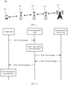
- FIG. 3 is a schematic flowchart of another communication processing method 300 according to an embodiment of this application.
- the method 300 may be applied to the communications system 100 shown in FIG. 1 , but this embodiment of this application is not limited thereto.
- a third relay node is a target node
- a second relay node and a first relay node are intermediate nodes
- a base station is a synchronization source node.
- the third relay node sends a synchronization request message to the base station via the second relay node and the first relay node, where the synchronization request message is used to request to perform clock synchronization with the base station.
- the base station receives the synchronization request message sent by the third relay node, and sends a synchronization response message to the third relay node via the first relay node and the second relay node, where the synchronization response message is used to indicate that the base station accepts a synchronization request of the third relay node.
- the base station agrees to serve as a synchronization source of the third relay node.
- the base station sends a third message to the third relay node via the first relay node and the second relay node, where the third message may include a sending time T 5 of the third message.
- the third message may further include at least one of identification information of the third relay node and identification information of the base station.
- the third message may be a Sync notification message.
- the third message may be periodically sent by the base station, or may be sent by the base station as triggered by an event.
- the base station may send the third message based on the synchronization request message of the third relay node. This is not limited in this embodiment of this application.
- the first relay node receives the third message, and adds waiting time information of the third message at the first relay node to the third message.
- a time at which the first relay node receives the third message is T 1 ′ rd
- a time at which the first relay node sends the third message is T 1 ′ td
- the first relay node may add T 1 ′ rd and T 1 ′ td , or T 1 ′ wd as the waiting time information of the third message at the first relay node. This is not limited in this embodiment of this application.
- the first relay node sends the third message to the second relay node.
- the second relay node receives the third message sent by the first relay node, and adds waiting time information of the third message at the second relay node to the third message.
- a time at which the second relay node receives the third message is T 2 ′ rd
- a time at which the second relay node sends the third message is T 2 ′ td
- the first relay node may add T 2 ′ rd and T 2 ′ td , or T 2 ′ wd as the waiting time information of the third message at the second relay node. This is not limited in this embodiment of this application.
- the second relay node sends the third message to the third relay node.
- the third relay node receives the third message sent by the second relay node, records a receiving time T6 of the third message, sends the first message to the base station via the second relay node and the first relay node, and records a sending time T1 of the first message.
- the first message may be a delay request message.
- the first message sent by the third relay node may include at least one of the following information: the sending time T1 of the first message at the third relay node, the identification information of the third relay node, and the identification information of the base station.
- the second relay node receives the first message sent by the third relay node, and adds waiting time information of the first message at the second relay node to the first message.
- a time at which the second relay node receives the first message is T 2 ru
- a time at which the second relay node sends the first message is T 2 tu
- the second relay node may add T 2 ru and T 2 tu , or T 2 tu as the waiting time information of the first message at the second relay node. This is not limited in this embodiment of this application.
- the second relay node sends the first message to the first relay node.
- the first relay node receives the first message sent by the second relay node, and adds waiting time information of the first message at the first relay node to the first message.
- a time at which the first relay node receives the first message is T 1 ru
- a time at which the first relay node sends the first message is T 1 tu
- the first relay node may add T 1 ru and T 1 tu , or T 1 wu as the waiting time information of the first message at the first relay node. This is not limited in this embodiment of this application.
- the first relay node sends the first message to the base station.
- the base station receives the first message sent by the first relay node, records a receiving time T 2 of the first message, and sends a second message to the third relay node via the first relay node and the second relay node.
- the second message may be a delay response message.
- the second message carries the receiving time T 2 of the first message at the base station and the waiting time information of the first message at the intermediate node, that is, the waiting time period T j wu (including the foregoing T 1 wu and T 2 wu ) of the first message at the intermediate node, or T j ru T j tu added by the intermediate node, where j is a number of the intermediate node and is an integer greater than or equal to 1.
- a quantity N of intermediate nodes is 2, and j is equal to 1 or 2.
- the second message may further carry at least one of the identification information of the base station and the identification information of the third relay node. This is not limited in this embodiment of this application.
- the first relay node receives the second message, and sends the second message to the second relay node.
- the second relay node receives the second message, and sends the second message to the third relay node.
- the third relay node receives the second message, to determine a clock deviation.
- the third relay node subtracts T from a current clock value, to implement clock synchronization with the base station.
- the intermediate node adds waiting time information to a message transmitted between the target node and the synchronization source node, so that the target node can calculate the clock deviation between the target node and the synchronization source node based on a sending time and receiving time of the message and a transmission delay of the message in a transmission process at the intermediate node, to perform clock adjustment.
- This can improve precision in clock synchronization between nodes in a multi-hop wireless relay scenario, and therefore improve system performance.
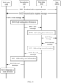
- FIG. 4 is a schematic flowchart of still another communication processing method 400 according to an embodiment of this application.
- the method 400 may be applied to the communications system 100 shown in FIG. 1 , but this embodiment of this application is not limited thereto.
- a third relay node is a target node
- a second relay node and a first relay node are intermediate nodes
- a base station is a synchronization source node.
- the third relay node sends a synchronization request message to the base station via the second relay node and the first relay node, where the synchronization request message is used to request to perform clock synchronization with the base station.
- the base station receives the synchronization request message sent by the third relay node, and sends a synchronization response message to the third relay node via the first relay node and the second relay node, where the synchronization response message is used to indicate that the base station accepts a synchronization request of the third relay node.
- the base station agrees to serve as a synchronization source of the third relay node.
- the third relay node sends a first message to the base station via the second relay node and the first relay node, where the first message may carry a sending time T 1 of the first message.
- the first message may further carry at least one of identification information of the third relay node and identification information of the base station.
- the first message may be a delay request message.
- the second relay node receives the first message, and adds waiting time information of the first message at the second relay node to the first message.
- a time at which the second relay node receives the first message is T 2 ru
- a time at which the second relay node sends the first message is T 2 tu
- the second relay node may add T 2 ru and T 2 tu , or T 2 wu as the waiting time information of the first message at the second relay node. This is not limited in this embodiment of this application.
- the second relay node sends the first message to the first relay node.
- the first relay node receives the first message sent by the second relay node, and adds waiting time information of the first message at the first relay node to the first message.
- a time at which the first relay node receives the first message is T 1 ru
- a time at which the first relay node sends the first message is T 1 tu
- the first relay node may add T 1 ru and T 1 tu , or T 1 wu as the waiting time information of the first message at the first relay node. This is not limited in this embodiment of this application.
- the first relay node sends the first message to the base station.
- the base station receives the first message sent by the first relay node, and records a receiving time T 2 of the first message.
- the base station sends a second message to the third relay node via the first relay node and the second relay node, and records a sending time T 3 of the second message, where the second message may be a delay response message.
- the second message carries the sending time T 3 of the second message at the base station, the receiving time T 2 of the first message at the base station, and the waiting time information of the first message at the intermediate node, that is, the waiting time period T j wu of the first message at the intermediate node (including the foregoing T 1 wu and T 2 wu ), or T j ru T j tu added by the intermediate node, where j is a number of the intermediate node and is an integer greater than or equal to 1.
- a quantity N of intermediate nodes is 2, and j is equal to 1 or 2.
- the second message may further carry at least one of the identification information of the third relay node and the identification information of the base station. This is not limited in this embodiment of this application.
- the first relay node receives the second message, and adds waiting time information of the second message at the first relay node to the second message.
- a time at which the first relay node receives the second message is T 1 rd
- a time at which the first relay node sends the second message is T 1 td
- the first relay node may add T 1 rd and T 1 td , or T 1 wd as the waiting time information of the second message at the first relay node. This is not limited in this embodiment of this application.
- the first relay node sends the second message to the second relay node.
- the second relay node receives the second message sent by the first relay node, and adds waiting time information of the second message at the second relay node to the second message.
- a time at which the second relay node receives the second message is T 2 rd
- a time at which the second relay node sends the second message is T 2 td
- the second relay node may add T 2 rd and T 2 td , or T 2 wd as the waiting time information of the second message at the second relay node. This is not limited in this embodiment of this application.
- the second relay node sends the second message to the third relay node.
- the third relay node receives the second message, and records a receiving time T 4 of the second message, to determine a clock deviation.
- the third relay node subtracts T from a current clock value of the third relay node, to implement clock synchronization with the base station.
- the intermediate node adds waiting time information to a message transmitted between the target node and the synchronization source node, so that the target node can calculate the clock deviation between the target node and the synchronization source node based on a sending time and receiving time of the message and a transmission delay of the message in a transmission process at the intermediate node, to perform clock adjustment.
- clock synchronization can be implemented through transferring of two messages. This reduces signaling interaction between the target node and the synchronization source node.
- FIG. 5 is a schematic flowchart of yet another communication processing method 500 according to an embodiment of this application.
- the method 500 may be applied to the communications system 100 shown in FIG. 1 , but this embodiment of this application is not limited thereto.
- a relay node is a target node
- a terminal device is an intermediate node
- a base station is a synchronization source node.
- the relay node sends a synchronization request message to the base station via the terminal device, where the synchronization request message is used by the relay node to request to perform clock synchronization with the base station.
- the base station receives the synchronization request message sent by the relay node via the terminal device, and sends a synchronization response message to the relay node via the terminal device.
- the synchronization response message is used to indicate that the base station receives a synchronization request of the relay node. In other words, the base station agrees to serve as a synchronization source of the relay node.
- the base station sends a third message to the relay node via the terminal device, where the third message may include a sending time T 5 of the third message.
- the third message may further include at least one of identification information of the relay node and identification information of the base station.
- the third message is a Sync notification message.
- the third message may be periodically sent by the base station, or may be sent by the base station as triggered by an event.
- the base station may send the third message based on the received synchronization request message of the relay node. This is not limited in this embodiment of this application.
- the terminal device receives the third message, and adds waiting time information of the third message at the terminal device to the third message.
- a time at which the terminal device receives the third message is T 1 rd
- a time at which the terminal device sends the third message is T 1 ′ td
- the terminal device may add T 1 rd and T 1 td , or T 1 wd as the waiting time information of the third message at the terminal device. This is not limited in this embodiment of this application.
- the terminal device sends the third message to the relay node.
- the relay node receives the third message sent by the terminal device, and records a receiving time T 6 of the third message.
- the relay node sends a first message to the base station via the terminal device, and records a time T 1 of sending the first message.
- the first message may be a delay request message.
- the first message sent by the relay node may include at least one of the following information: the sending time T 1 of the first message at the relay node, the identification information of the relay node, and the identification information of the base station.
- the terminal device receives the first message, and adds waiting time information of the first message at the terminal device to the first message.
- a time at which the terminal device receives the first message is T 1 ru
- a time at which the terminal device sends the first message is T 1 tu
- the terminal device may add T 1 ru and T 1 tu , or T 1 wu as the waiting time information of the first message at the terminal device. This is not limited in this embodiment of this application.
- the terminal device sends the first message to the base station.
- the base station receives the first message sent by the terminal device, records a receiving time T 2 of the first message, and sends a second message to the relay node via the terminal device, where the second message may be a delay response message.
- the second message carries the receiving time T 2 of the first message at the base station and the waiting time information of the first message at the intermediate node, that is, the waiting time period T j wu (including the foregoing T 1 wu ) of the first message at the intermediate node, or T j ru T j tu added by the intermediate node, where j is a number of the intermediate node and is an integer greater than or equal to 1.
- a quantity N of intermediate nodes is 1, and j is 1.
- the second message may further carry at least one of the identification information of the base station and the identification information of the third relay node. This is not limited in this embodiment of this application.
- the terminal device receives the second message, and sends the second message to the relay node.
- the relay node receives the second message, to determine a clock deviation.
- the relay node subtracts T from a current clock value, to implement clock synchronization between the relay node and the base station.
- the intermediate node adds waiting time information to a message transmitted between the target node and the synchronization source node, so that the target node can calculate the clock deviation between the target node and the synchronization source node based on a sending time and receiving time of the message and a transmission delay of the message in a transmission process at the intermediate node, to perform clock adjustment.
- This can improve precision in clock synchronization between nodes in a multi-hop wireless relay scenario, and therefore improve system performance.
- synchronization between sites helps reduce interference.
- FIG. 6 is a schematic flowchart of still yet another communication processing method 600 according to an embodiment of this application.
- the method 600 may be applied to the communications system 100 shown in FIG. 1 , but this embodiment of this application is not limited thereto.
- a relay node is a target node
- a terminal device is an intermediate node
- a base station is a synchronization source node.
- the relay node sends a synchronization request message to the base station via the terminal device, where the synchronization request message is used by the relay node to request to perform clock synchronization with the base station.
- the base station receives the synchronization request message sent by the relay node via the terminal device, and sends a synchronization response message to the relay node via the terminal device.
- the synchronization response message is used to indicate that the base station accepts a synchronization request of the relay node. In other words, the base station agrees to serve as a synchronization source of the relay node.
- the relay node sends a first message to the base station via the terminal device, and records a sending time T 1 of the first message.
- the first message may carry at least one of the following information: the time T 1 at which the relay node sends the first message, identification information of the relay node, and identification information of the base station.
- the first message may be a delay request message.
- the terminal device receives the first message, and adds waiting time information of the first message at the terminal device to the first message.
- a time at which the terminal device receives the first message is T 1 ru
- a time at which the terminal device sends the first message is T 1 tu
- the terminal device may add T 1 ru and T 1 tu , or T 1 wu as the waiting time information of the first message at the terminal device. This is not limited in this embodiment of this application.
- the terminal device sends the first message to the base station.
- the base station receives the first message, and records a receiving time T 2 of the first message.
- the base station sends a second message to the relay node via the terminal device, and records a sending time T 3 at which the base station sends the second message, where the second message may be a delay response message.
- the second message carries the sending time T 3 of the second message at the base station, the receiving time T 2 of the first message at the base station, and the waiting time information of the first message at the terminal device, that is, the waiting time period T j wu (including the foregoing T 1 wu ) of the first message at the terminal device, or T j ru T j tu added by the terminal device, where j is a number of the intermediate node and is an integer greater than or equal to 1.
- a quantity N of intermediate nodes is 1, and j is 1.
- the second message may further carry at least one of the identification information of the relay node and the identification information of the base station. This is not limited in this embodiment of this application.
- the terminal device receives the second message, and adds waiting time information of the second message at the terminal device to the second message.
- a time at which the terminal device receives the second message is T 1 rd
- a time at which the terminal device sends the second message is T 1 td
- the terminal device may add T 1 rd and T 1 td , or T 1 wd as the waiting time information of the second message at the terminal device. This is not limited in this embodiment of this application.
- the terminal device sends the second message to the relay node.
- the relay node receives the second message, and records a receiving time T 4 of the second message, to determine a clock deviation.
- the third relay node subtracts T from a current clock value of the third relay node, to implement clock synchronization between the relay node and the base station.
- the intermediate node adds waiting time information to a message transmitted between the target node and the synchronization source node, so that the target node can calculate the clock deviation between the target node and the synchronization source node based on a sending time and receiving time of the message and a transmission delay of the message in a transmission process at the intermediate node, to perform clock adjustment.
- clock synchronization can be implemented through transferring of two messages. This reduces signaling interaction between the target node and the synchronization source node.
- synchronization between sites helps reduce interference.
- sequence numbers of the foregoing processes do not mean execution sequences.
- the execution sequences of the processes should be determined according to functions and internal logic of the processes, and should not be construed as any limitation on the implementation processes of the embodiments of this application.
- FIG. 7 shows a communication processing apparatus 700 according to an embodiment of this application.
- the apparatus 700 includes a transceiver unit 710 and a processing unit 720.
- the apparatus 700 may be specifically the target node in the foregoing embodiments, and the apparatus 700 may be configured to perform procedures and/or steps corresponding to the target node in the foregoing method embodiments.
- the transceiver unit 710 is configured to receive a second message sent by a synchronization source node via at least one intermediate node, where the second message carries a receiving time of a first message from the apparatus at the synchronization source node and waiting time information of the first message at each of the at least one intermediate node.
- the processing unit 720 is configured to determine a clock deviation between the apparatus and the synchronization source node based on a sending time of the first message at the apparatus and the time information in the second message.
- the intermediate node adds waiting time information to a message transmitted between the target node and the synchronization source node, so that the target node can calculate the clock deviation between the target node and the synchronization source node based on a sending time and receiving time of the message and a transmission delay of the message in a transmission process at the intermediate node, to perform clock adjustment.
- This can improve precision in clock synchronization between nodes in a multi-hop wireless relay scenario, and therefore improve system performance.
- the second message further carries a sending time of the second message at the synchronization source node and waiting time information of the second message at each intermediate node.
- the processing unit 720 is specifically configured to determine the clock deviation between the apparatus and the synchronization source node based on the sending time of the first message at the apparatus, a receiving time of the second message at the apparatus, and the time information in the second message.
- T 4 is the receiving time of the second message at the apparatus
- T 3 is a sending time of the second message at the synchronization source node
- T 2 is the receiving time of the first message at the synchronization source node
- T 1 is the sending time of the first message at the apparatus.
- a quantity of the at least one intermediate node is N, where N is an integer greater than or equal to 1.
- T j wd is a waiting time of the second message at an intermediate node j
- T j wu is a waiting time of the first message at the intermediate node j.
- the transceiver unit 710 is further configured to: before sending the first message to the synchronization source node via the at least one intermediate node, receive a third message sent by the synchronization source node via the at least one intermediate node, where the third message carries a sending time of the third message at the synchronization source node and waiting time information of the third message at each intermediate node.
- the transceiver unit 710 is further configured to send the first message to the synchronization source node based on the third message via the at least one intermediate node.
- the processing unit 720 is specifically configured to determine the clock deviation between the apparatus and the synchronization source node based on the sending time of the first message at the apparatus, the time information in the second message, a receiving time of the third message at the apparatus, and the time information in the third message.
- T 6 is the receiving time of the third message at the apparatus
- T 5 is the sending time of the third message at the synchronization source node
- T 2 is the receiving time of the first message at the synchronization source node
- T 1 is the sending time of the first message at the apparatus.
- a quantity of the at least one intermediate node is N, where N is an integer greater than or equal to 1.
- T j ′ wd is a waiting time of the third message at the intermediate node j
- T j wu is the waiting time of the first message at the intermediate node j .
- the transceiver unit 710 is further configured to: before receiving the second message sent by the synchronization source node via the at least one intermediate node, send a synchronization request message to the synchronization source node via the at least one intermediate node, where the synchronization request message is used to request to perform clock synchronization with the synchronization source node.
- the transceiver unit 710 is further configured to receive a synchronization response message sent by the synchronization source node via the at least one intermediate node, where the synchronization response message is used to indicate that the synchronization source node accepts or rejects a synchronization request of the apparatus.
- the third message is sent by the synchronization source node and the at least one intermediate node in a broadcast or multicast manner.
- the transceiver unit 710 is further configured to send a fourth message, where the fourth message is used to indicate a hop count between the apparatus and the synchronization source node, and the hop count is used by another apparatus to determine whether to perform clock synchronization with the apparatus.
- the apparatus 700 may be specifically the synchronization source node in the foregoing embodiments, and the apparatus 700 may be configured to perform procedures and/or steps corresponding to the synchronization source node in the foregoing method embodiments.
- the transceiver unit 710 is configured to: receive a first message sent by a target node via at least one intermediate node, where the first message carries waiting time information of the first message at each of the at least one intermediate node; and send a second message to the target node based on the first message via the at least one intermediate node, where the second message carries a receiving time of the first message at the apparatus and the waiting time information of the first message at each of the at least one intermediate node.
- the intermediate node adds waiting time information to a message transmitted between the target node and the synchronization source node, so that the target node can calculate the clock deviation between the target node and the synchronization source node based on a sending time and receiving time of the message and a transmission delay of the message in a transmission process at the intermediate node, to perform clock adjustment.
- This can improve precision in clock synchronization between nodes in a multi-hop wireless relay scenario, and therefore improve system performance.
- the second message further carries a sending time of the second message at the apparatus.
- the transceiver unit 710 is further configured to: before receiving the first message sent by the target node via the at least one intermediate node, send a third message to the target node via the at least one intermediate node, where the third message carries a sending time of the third message at the apparatus.
- the transceiver unit 710 is further configured to: before receiving the first message sent by the target node via the at least one intermediate node, receive a synchronization request message sent by the target node, where the synchronization request message is used to request to perform clock synchronization with the apparatus; and send a synchronization response message to the target node based on the synchronization request message via the at least one intermediate node, where the synchronization response message is used to indicate that the apparatus accepts or rejects a synchronization request of the target node.
- the third message is sent by the apparatus in a broadcast or multicast manner.
- the apparatus 700 may be specifically the first intermediate node in the foregoing embodiments, and the apparatus 700 may be configured to perform procedures and/or steps corresponding to the first intermediate node in the foregoing method embodiments.
- the processing unit 720 is configured to add waiting time information of a first message at the apparatus to the first message from a target node.
- the transceiver unit 710 is configured to: send the first message; receive a second message, where the second message carries a receiving time of the first message at the synchronization source node and waiting time information of the first message at each of at least one intermediate node, and the at least one intermediate node includes the apparatus; and send the second message.
- the intermediate node adds waiting time information to a message transmitted between the target node and the synchronization source node, so that the target node can calculate the clock deviation between the target node and the synchronization source node based on a sending time and receiving time of the message and a transmission delay of the message in a transmission process at the intermediate node, to perform clock adjustment.
- This can improve precision in clock synchronization between nodes in a multi-hop wireless relay scenario, and therefore improve system performance.
- processing unit 720 is further configured to: before the second message is sent, add waiting time information of the second message at the apparatus to the second message.
- the transceiver unit 710 is further configured to: before the waiting time information of the first message at the apparatus is added to the first message from the target node, receive a third message, where the third message carries a sending time of the third message at the synchronization source node.
- the processing unit 720 is further configured to add waiting time information of the third message at the apparatus to the third message.
- the transceiver unit 710 is further configured to send the third message.
- the third message is sent by the synchronization source node and the apparatus in a broadcast or multicast manner.
- the transceiver unit 710 is further configured to: before the waiting time information of the first message at the first intermediate node is added to the first message from the target node, receive a synchronization request message, where the synchronization request message is used to request to perform clock synchronization with the synchronization source node; forward the synchronization request message; receive a synchronization response message, where the synchronization response message is used to indicate that the synchronization source node accepts or rejects a synchronization request of the target node; and forward the synchronization response message.
- the transceiver unit 710 is further configured to send a fifth message, where the fifth message is used to indicate a hop count between the apparatus and the synchronization source node, and the hop count is used by another target node to determine whether to perform clock synchronization with the apparatus.
- the apparatus is a terminal device or a relay node.
- unit herein may refer to an application-specific integrated circuit (application specific integrated circuit, ASIC), an electronic circuit, a processor (for example, a shared processor, a special purpose processor, or a group processor) configured to execute one or more software or firmware programs, a memory, a merge logic circuit, and/or another suitable component that supports the described function.
- ASIC application specific integrated circuit
- the communication processing apparatus may include a chip, or may be a chip.
- the chip may include a memory, a processor, and a communications interface.
- the processor and the memory communicate with each other by using an internal connection path.
- the processor is configured to execute code in the memory. When the code is executed, the processor is configured to perform procedures and/or steps corresponding to the foregoing apparatus 700. Details are not described herein again.
- FIG. 8 shows another communication processing apparatus 800 according to an embodiment of this application.
- the apparatus 800 includes a processor 810, a transceiver 820, and a memory 830.
- the processor 810, the transceiver 820, and the memory 830 communicate with each other by using an internal connection path.
- the memory 830 is configured to store an instruction.
- the processor 810 is configured to execute the instruction stored in the memory 830, to control the transceiver 820 to send a signal and/or receive a signal.
- the apparatus 800 may be specifically the target node in the foregoing embodiments, and may be configured to perform the steps and/or procedures corresponding to the target node in the foregoing method embodiments.
- the transceiver 820 is configured to receive a second message sent by a synchronization source node via at least one intermediate node, where the second message carries a receiving time of a first message from the apparatus at the synchronization source node and waiting time information of the first message at each of the at least one intermediate node.
- the processor 810 is configured to determine a clock deviation between the apparatus and the synchronization source node based on a sending time of the first message at the apparatus and the second message.
- the apparatus 800 may be specifically the synchronization source node in the foregoing embodiments, and may be configured to perform the steps and/or procedures corresponding to the synchronization source node in the foregoing method embodiments.
- the transceiver 820 is configured to: receive a first message sent by a target node via at least one intermediate node, where the first message carries waiting time information of the first message at each of the at least one intermediate node; and send a second message to the target node based on the first message via the at least one intermediate node, where the second message carries a receiving time of the first message at the apparatus and the waiting time information of the first message at each of the at least one intermediate node.
- the apparatus 800 may be specifically the first intermediate node in the foregoing embodiments, and may be configured to perform the steps and/or procedures corresponding to the first intermediate node in the foregoing method embodiments.
- the processor 810 is configured to add waiting time information of a first message at the apparatus to the first message from a target node.
- the transceiver 820 is configured to: send the first message; receive a second message, where the second message carries a receiving time of the first message at the synchronization source node and waiting time information of the first message at each of at least one intermediate node, and the at least one intermediate node includes the apparatus; and send the second message.
- the memory 830 includes a read-only memory and a random access memory, and provides an instruction and data to the processor.
- a part of the memory may further include a non-volatile random access memory.
- the memory may further store information of a device type.
- the processor 810 may be configured to execute the instruction stored in the memory.
- the processor 810 executes the instruction stored in the memory, the processor 810 is configured to perform the steps and/or the procedures corresponding to the first intermediate node in the method embodiments.
- the processor in the foregoing apparatus may be a central processing unit (central processing unit, CPU), or the processor may be another general purpose processor, a digital signal processor (DSP), an application-specific integrated circuit (ASIC), a field programmable gate array (FPGA), or another programmable logic device, discrete gate or transistor logic device, discrete hardware component, or the like.
- the general purpose processor may be a microprocessor, or the processor may be any conventional processor or the like.
- steps in the foregoing methods can be implemented by using a hardware integrated logical circuit in the processor, or by using an instruction in a form of software.
- the steps of the method disclosed with reference to the embodiments of this application may be directly performed by a hardware processor, or may be performed by using a combination of hardware in the processor and a software unit.
- a software unit may be located in a mature storage medium in the art, such as a random access memory, a flash memory, a read-only memory, a programmable read-only memory, an electrically erasable programmable memory, or a register.
- the storage medium is located in the memory, and a processor reads an instruction in the memory and performs the steps in the foregoing methods in combination with hardware of the processor. To avoid repetition, details are not described herein again.
- the disclosed system, apparatus, and method may be implemented in other manners.
- the described apparatus embodiment is merely an example.
- division into units is merely logical function division and may be other division in actual implementation.
- a plurality of units or components may be combined or integrated into another system, or some features may be ignored or not performed.
- the displayed or discussed mutual couplings or direct couplings or communication connections may be implemented through some interfaces, indirect couplings or communication connections between the apparatuses or units, or electrical connections, mechanical connections, or connections in other forms.
- the units described as separate parts may or may not be physically separate, and parts displayed as units may or may not be physical units, may be located in one position, or may be distributed on a plurality of network units. Some or all of the units may be selected according to actual requirements to achieve the objectives of the solutions of the embodiments in this application.
- function units in the embodiments of this application may be integrated into one processing unit, or each of the units may exist alone physically, or two or more units are integrated into one unit.
- the integrated unit may be implemented in a form of hardware, or may be implemented in a form of a software function unit.
- the integrated unit When the integrated unit is implemented in the form of a software function unit and sold or used as an independent product, the integrated unit may be stored in a computer-readable storage medium. Based on such an understanding, the technical solutions of this application essentially, or the part contributing to the prior art, or all or some of the technical solutions may be implemented in a form of a software product.
- the software product is stored in a storage medium and includes several instructions for instructing a computer device (which may be a personal computer, a server, or a network device) to perform all or some of the steps of the methods described in the embodiments of this application.
- the foregoing storage medium includes: any medium that can store program code, such as a USB flash drive, a removable hard disk, a read-only memory (read-only memory, ROM), a random access memory (random access memory, RAM), a magnetic disk, or an optical disc.
- program code such as a USB flash drive, a removable hard disk, a read-only memory (read-only memory, ROM), a random access memory (random access memory, RAM), a magnetic disk, or an optical disc.
Landscapes
- Engineering & Computer Science (AREA)
- Computer Networks & Wireless Communication (AREA)
- Signal Processing (AREA)
- Mobile Radio Communication Systems (AREA)
Claims (15)
- Procédé de traitement de communication, comprenant :la réception (S240), par un noeud cible, d'un deuxième message envoyé par un noeud source de synchronisation par l'intermédiaire d'au moins un noeud intermédiaire, dans lequel le deuxième message achemine un temps de réception d'un premier message à partir du noeud cible au niveau du noeud source de synchronisation et des informations de temps d'attente du premier message au niveau de chacun de l'au moins un noeud intermédiaire ; etla détermination (S260), par le noeud cible, d'une déviation d'horloge entre le noeud cible et le noeud source de synchronisation sur la base d'un temps d'envoi du premier message au niveau du noeud cible et des informations temporelles dans le deuxième message ;le procédé étant caractérisé par :
l'envoi, par le noeud cible, d'un quatrième message, dans lequel le quatrième message est utilisé pour indiquer un compte de saut entre le noeud cible et le noeud source de synchronisation, et le compte de saut est utilisé par un autre noeud cible pour déterminer s'il faut exécuter une synchronisation d'horloge avec le noeud cible. - Procédé selon la revendication 1, dans lequel le deuxième message achemine en outre un temps d'envoi du deuxième message au niveau du noeud source de synchronisation et des informations de temps d'attente du deuxième message au niveau de chaque noeud intermédiaire ; et
la détermination, par le noeud cible, d'une déviation d'horloge entre le noeud cible et le noeud source de synchronisation sur la base d'un temps d'envoi du premier message au niveau du noeud cible et des informations temporelles dans le deuxième message comprend :
la détermination, par le noeud cible, de la déviation d'horloge entre le noeud cible et le noeud source de synchronisation sur la base du temps d'envoi du premier message au niveau du noeud cible, d'un temps de réception du deuxième message au niveau du noeud cible et des informations temporelles dans le deuxième message. - Procédé selon la revendication 1, avant l'envoi, par le noeud cible, d'un premier message au noeud source de synchronisation par l'intermédiaire d'au moins un noeud intermédiaire, le procédé comprenant en outre :la réception (S303, S305, S307), par le noeud cible, d'un troisième message envoyé par le noeud source de synchronisation par l'intermédiaire de l'au moins un noeud intermédiaire, dans lequel le troisième message achemine un temps d'envoi du troisième message au niveau du noeud source de synchronisation et des informations de temps d'attente du troisième message au niveau de chaque noeud intermédiaire ; etl'envoi (S308, S310, S312), par le noeud cible sur la base du troisième message, du premier message au noeud source de synchronisation par l'intermédiaire de l'au moins un noeud intermédiaire ; etla détermination, par le noeud cible, d'une déviation d'horloge entre le noeud cible et le noeud source de synchronisation sur la base d'un temps d'envoi du premier message au niveau du noeud cible et des informations temporelles dans le deuxième message comprenant :
la détermination (S316), par le noeud cible, de la déviation d'horloge entre le noeud cible et le noeud source de synchronisation sur la base du temps d'envoi du premier message au niveau du noeud cible, des informations temporelles dans le deuxième message, d'un temps de réception du troisième message au niveau du noeud cible et des informations temporelles dans le troisième message. - Procédé selon la revendication 3, dans lequel le troisième message est envoyé par le noeud source de synchronisation et l'au moins un noeud intermédiaire d'une manière de diffusion ou de multidiffusion.
- Procédé de traitement de communication, comprenant :l'ajout (S220), par un premier noeud intermédiaire, d'informations de temps d'attente d'un premier message au niveau du premier noeud intermédiaire au premier message en provenance d'un noeud cible ;l'envoi (S230), par le premier noeud intermédiaire, du premier message ;la réception (S240), par le premier noeud intermédiaire, d'un deuxième message, dans lequel le deuxième message achemine un temps de réception du premier message au niveau d'un noeud source de synchronisation et des informations de temps d'attente du premier message au niveau de chacun d'au moins un noeud intermédiaire, et l'au moins un noeud intermédiaire comprend le premier noeud intermédiaire ; etl'envoi (S250), par le premier noeud intermédiaire, du deuxième message ;le procédé étant caractérisé par :
l'envoi, par le premier noeud intermédiaire, d'un cinquième message, dans lequel le cinquième message est utilisé pour indiquer un compte de saut entre le premier noeud intermédiaire et le noeud source de synchronisation, et le compte de saut est utilisé par un autre noeud cible pour déterminer s'il faut exécuter une synchronisation d'horloge avec le premier noeud intermédiaire. - Procédé selon la revendication 5, avant l'envoi, par le premier noeud intermédiaire, du deuxième message, le procédé comprenant en outre :
l'ajout, par le premier noeud intermédiaire, d'informations de temps d'attente du deuxième message au niveau du premier noeud intermédiaire au deuxième message. - Procédé selon la revendication 5, avant l'envoi, par un premier noeud intermédiaire, d'informations de temps d'attente d'un premier message au niveau du premier noeud intermédiaire au premier message en provenance d'un noeud cible, le procédé comprenant en outre :la réception (S303, S305 ; S503), par le premier noeud intermédiaire, d'un troisième message, dans lequel le troisième message achemine un temps d'envoi du troisième message au niveau du noeud source de synchronisation ;l'ajout (S304, S306 ; S504), par le premier noeud intermédiaire, d'informations de temps d'attente du troisième message au niveau du premier noeud intermédiaire au troisième message ; etl'envoi (S307 ; S505), par le premier noeud intermédiaire, du troisième message.
- Procédé selon la revendication 7, dans lequel le troisième message est envoyé par le noeud source de synchronisation et le premier noeud intermédiaire d'une manière de diffusion ou de multidiffusion.
- Procédé selon l'une quelconque des revendications 5 à 8, dans lequel le premier noeud intermédiaire est un dispositif terminal ou un noeud relais.
- Appareil, qui est configuré pour exécuter le procédé selon l'une quelconque des revendications 1 à 4.
- Appareil, qui est configuré pour exécuter le procédé selon l'une quelconque des revendications 5 à 9.
- Système de traitement de communication, comprenant l'appareil selon la revendication 10, et l'appareil selon la revendication 11.
- Support lisible par ordinateur, configuré pour stocker un programme informatique, dans lequel le programme informatique comprend une instruction qui, lorsqu'elle est exécutée par un ordinateur, permet à l'ordinateur de mettre en oeuvre le procédé selon l'une quelconque des revendications 1 à 4.
- Produit de programme informatique, le produit de programme informatique comprenant un code de programme informatique, et lorsque le code de programme informatique est exécuté sur un ordinateur, l'ordinateur étant activé pour mettre en oeuvre le procédé selon l'une quelconque des revendications 5 à 9.
- Puce, comprenant : un processeur, configuré pour lire une instruction stockée dans une mémoire, et lorsque le processeur exécute l'instruction, la puce est activée pour exécuter le procédé selon l'une quelconque des revendications 1 à 9.
Applications Claiming Priority (2)
| Application Number | Priority Date | Filing Date | Title |
|---|---|---|---|
| CN201711202769.1A CN109842455B (zh) | 2017-11-27 | 2017-11-27 | 通信处理方法和装置 |
| PCT/CN2018/115015 WO2019100963A1 (fr) | 2017-11-27 | 2018-11-12 | Procédé et dispositif de traitement de communications |
Publications (3)
| Publication Number | Publication Date |
|---|---|
| EP3694121A1 EP3694121A1 (fr) | 2020-08-12 |
| EP3694121A4 EP3694121A4 (fr) | 2020-12-23 |
| EP3694121B1 true EP3694121B1 (fr) | 2024-09-25 |
Family
ID=66631816
Family Applications (1)
| Application Number | Title | Priority Date | Filing Date |
|---|---|---|---|
| EP18881787.8A Active EP3694121B1 (fr) | 2017-11-27 | 2018-11-12 | Procédé et dispositif de traitement de communications |
Country Status (4)
| Country | Link |
|---|---|
| US (1) | US11191050B2 (fr) |
| EP (1) | EP3694121B1 (fr) |
| CN (1) | CN109842455B (fr) |
| WO (1) | WO2019100963A1 (fr) |
Families Citing this family (9)
| Publication number | Priority date | Publication date | Assignee | Title |
|---|---|---|---|---|
| US11218981B2 (en) * | 2018-09-20 | 2022-01-04 | Kabushiki Kaisha Toshiba | Wireless mesh network and data transmission method |
| CN111258209A (zh) * | 2018-12-25 | 2020-06-09 | 维沃移动通信有限公司 | 一种时间信息的获取方法、发送方法、终端和网络设备 |
| US11477743B2 (en) * | 2019-05-03 | 2022-10-18 | Qualcomm Incorporated | Methods and apparatus for communication of synchronization reliability |
| US11316781B2 (en) * | 2019-07-26 | 2022-04-26 | Qualcomm Incorporated | Separation of a control plane and a user plane for an integrated access and backhaul network |
| CN110492967B (zh) * | 2019-09-24 | 2021-11-02 | 瑞斯康达科技发展股份有限公司 | 一种时间同步方法、中继设备及装置 |
| CN110933096A (zh) * | 2019-12-05 | 2020-03-27 | 北京邮电大学 | 软件定义的网络授时系统及授时方法 |
| CN115118321A (zh) * | 2021-03-17 | 2022-09-27 | 北京新岸线移动通信技术有限公司 | 一种无线通信中继系统通过空口传递gps信号的方法及系统 |
| CN113225768B (zh) * | 2021-04-29 | 2023-02-10 | 北京凯视达信息技术有限公司 | 一种4g/5g传输网络的同步方法 |
| US11539452B2 (en) * | 2021-06-01 | 2022-12-27 | Ciena Corporation | Signaling the distributed 1588v2 clock accuracy relative to UTC |
Family Cites Families (16)
| Publication number | Priority date | Publication date | Assignee | Title |
|---|---|---|---|---|
| US7426190B2 (en) * | 2005-09-30 | 2008-09-16 | Robert Bosch Gmbh | System and method for a communication protocol for wireless sensor systems including systems with high priority asynchronous message and low priority synchronous message |
| US20080043747A1 (en) * | 2006-08-04 | 2008-02-21 | Haihong Zheng | Apparatus, method, system and software product for a scheduling synchronization mechanism in a multi-hop environment |
| US8213405B2 (en) * | 2008-02-01 | 2012-07-03 | Qualcomm Incorporated | Wireless network synchronization |
| US20100014460A1 (en) * | 2008-07-11 | 2010-01-21 | Electronics And Telecommunications Research Institute | Sensor network mac system for multihop communication |
| CN101510849B (zh) * | 2009-03-18 | 2011-05-18 | 中国电信股份有限公司 | 获取传输路径上节点传输信息的方法和系统 |
| JP5853788B2 (ja) * | 2012-03-16 | 2016-02-09 | 富士通株式会社 | 伝送装置、伝送方法及び伝送帯域の変更方法 |
| US8879586B2 (en) * | 2012-12-20 | 2014-11-04 | Broadcom Corporation | Inband timestamping |
| CN103078699B (zh) * | 2012-12-28 | 2015-08-05 | 华为技术有限公司 | 基于精密时间协议进行时间同步的方法和网络设备 |
| JP6134622B2 (ja) * | 2013-09-24 | 2017-05-24 | 株式会社日立製作所 | 通信システム及び時刻同期方法 |
| CN103957589B (zh) * | 2014-04-01 | 2017-03-29 | 安徽工程大学 | 一种多跳低开销的分布式时钟同步方法 |
| CN104105195A (zh) * | 2014-06-27 | 2014-10-15 | 山东大学(威海) | 一种基于时钟频率动态检测的大规模无线传感器网络时间同步器 |
| KR101596759B1 (ko) * | 2014-11-26 | 2016-03-07 | 현대자동차주식회사 | 차량용 이더넷 통신망에서의 시간 동기화 제공 방법 및 장치 |
| WO2016092244A1 (fr) * | 2014-12-11 | 2016-06-16 | Khalifa University of Science, Technology, and Research | Procédé et dispositifs de transfert temporel à l'aide d'horloges transparentes poste à poste |
| CN105141390B (zh) * | 2015-09-16 | 2018-10-30 | 浙江神州量子网络科技有限公司 | 一种量子网络中的时间同步方法 |
| JP2017098694A (ja) * | 2015-11-20 | 2017-06-01 | 富士通株式会社 | 通信装置,及びその時刻同期方法 |
| US11076370B2 (en) * | 2016-06-07 | 2021-07-27 | Texas Instruments Incorporated | Node synchronization for networks |
-
2017
- 2017-11-27 CN CN201711202769.1A patent/CN109842455B/zh active Active
-
2018
- 2018-11-12 WO PCT/CN2018/115015 patent/WO2019100963A1/fr not_active Ceased
- 2018-11-12 EP EP18881787.8A patent/EP3694121B1/fr active Active
-
2020
- 2020-05-27 US US16/884,320 patent/US11191050B2/en active Active
Also Published As
| Publication number | Publication date |
|---|---|
| CN109842455A (zh) | 2019-06-04 |
| EP3694121A1 (fr) | 2020-08-12 |
| US11191050B2 (en) | 2021-11-30 |
| WO2019100963A1 (fr) | 2019-05-31 |
| CN109842455B (zh) | 2020-06-16 |
| EP3694121A4 (fr) | 2020-12-23 |
| US20200288420A1 (en) | 2020-09-10 |
Similar Documents
| Publication | Publication Date | Title |
|---|---|---|
| EP3694121B1 (fr) | Procédé et dispositif de traitement de communications | |
| US20240129869A1 (en) | Time-Synchronized Radio Bearer For Supporting Precision Timing Protocol (PTP) Based Time Sensitive Network (TSN) Applications | |
| JP7584568B2 (ja) | サイドリンクチャネルリソースユニットの構成のための方法および装置 | |
| CN104885396B (zh) | 用于实现和执行在无线电信网络中的无线设备之间的d2d通信中的harq传输的网络节点、无线设备以及其中的方法 | |
| EP3858016B1 (fr) | Procédé et appareil de configuration d'unités de ressource de canal de liaison latérale | |
| US11395320B2 (en) | Predictive scheduling request or buffer status report for wireless backhauling | |
| CN102811494B (zh) | 一种数据传输方法和装置 | |
| CN114024812B (zh) | 一种prs资源的配置方法及装置、用户设备、网络设备 | |
| EP4109787B1 (fr) | Appareil et procédé de synchronisation | |
| CN110431914B (zh) | 具有用户设备终端能力的远程射频头 | |
| CN112771957B (zh) | 用于配置基于调度的边链路资源的方法和装置 | |
| CN111800852A (zh) | 一种时延补偿及其控制方法及装置 | |
| CN115696556A (zh) | 一种时延补偿及其控制方法及装置 | |
| CN110891316A (zh) | 一种时域资源配置方法及接入网设备 | |
| CN112997552B (zh) | 用于配置侧链路信道资源单元的方法和装置 | |
| WO2019154336A1 (fr) | Procédé de commande de puissance et dispositif de communication | |
| WO2021056564A1 (fr) | Procédé et dispositif de traitement d'opération de liaison latérale, et support de stockage | |
| US9986535B2 (en) | Method and system for managing mobile management entity (MME) in a telecommunication network | |
| CN113632548B (zh) | 无线通信的方法、终端设备和网络设备 | |
| US10314010B2 (en) | Apparatus for radio communication systems | |
| KR20230009472A (ko) | 자원 다중화 방법 및 장치 | |
| CN104160758B (zh) | 用于在下行链路协调多点传送场景中的节点的频率同步方法 | |
| WO2018171757A1 (fr) | Procédé et dispositif de configuration d'accès aléatoire | |
| WO2023051407A1 (fr) | Procédé et appareil de communication | |
| TW202446123A (zh) | 無線電存取網路中的鄰近服務 |
Legal Events
| Date | Code | Title | Description |
|---|---|---|---|
| STAA | Information on the status of an ep patent application or granted ep patent |
Free format text: STATUS: THE INTERNATIONAL PUBLICATION HAS BEEN MADE |
|
| PUAI | Public reference made under article 153(3) epc to a published international application that has entered the european phase |
Free format text: ORIGINAL CODE: 0009012 |
|
| STAA | Information on the status of an ep patent application or granted ep patent |
Free format text: STATUS: REQUEST FOR EXAMINATION WAS MADE |
|
| 17P | Request for examination filed |
Effective date: 20200504 |
|
| AK | Designated contracting states |
Kind code of ref document: A1 Designated state(s): AL AT BE BG CH CY CZ DE DK EE ES FI FR GB GR HR HU IE IS IT LI LT LU LV MC MK MT NL NO PL PT RO RS SE SI SK SM TR |
|
| AX | Request for extension of the european patent |
Extension state: BA ME |
|
| A4 | Supplementary search report drawn up and despatched |
Effective date: 20201123 |
|
| RIC1 | Information provided on ipc code assigned before grant |
Ipc: H04J 3/06 20060101AFI20201117BHEP |
|
| DAV | Request for validation of the european patent (deleted) | ||
| DAX | Request for extension of the european patent (deleted) | ||
| GRAP | Despatch of communication of intention to grant a patent |
Free format text: ORIGINAL CODE: EPIDOSNIGR1 |
|
| STAA | Information on the status of an ep patent application or granted ep patent |
Free format text: STATUS: GRANT OF PATENT IS INTENDED |
|
| INTG | Intention to grant announced |
Effective date: 20240524 |
|
| GRAS | Grant fee paid |
Free format text: ORIGINAL CODE: EPIDOSNIGR3 |
|
| GRAA | (expected) grant |
Free format text: ORIGINAL CODE: 0009210 |
|
| STAA | Information on the status of an ep patent application or granted ep patent |
Free format text: STATUS: THE PATENT HAS BEEN GRANTED |
|
| AK | Designated contracting states |
Kind code of ref document: B1 Designated state(s): AL AT BE BG CH CY CZ DE DK EE ES FI FR GB GR HR HU IE IS IT LI LT LU LV MC MK MT NL NO PL PT RO RS SE SI SK SM TR |
|
| REG | Reference to a national code |
Ref country code: GB Ref legal event code: FG4D |
|
| REG | Reference to a national code |
Ref country code: CH Ref legal event code: EP |
|
| REG | Reference to a national code |
Ref country code: DE Ref legal event code: R096 Ref document number: 602018074809 Country of ref document: DE |
|
| REG | Reference to a national code |
Ref country code: IE Ref legal event code: FG4D |
|
| REG | Reference to a national code |
Ref country code: LT Ref legal event code: MG9D |
|
| PG25 | Lapsed in a contracting state [announced via postgrant information from national office to epo] |
Ref country code: NO Free format text: LAPSE BECAUSE OF FAILURE TO SUBMIT A TRANSLATION OF THE DESCRIPTION OR TO PAY THE FEE WITHIN THE PRESCRIBED TIME-LIMIT Effective date: 20241225 |
|
| PG25 | Lapsed in a contracting state [announced via postgrant information from national office to epo] |
Ref country code: GR Free format text: LAPSE BECAUSE OF FAILURE TO SUBMIT A TRANSLATION OF THE DESCRIPTION OR TO PAY THE FEE WITHIN THE PRESCRIBED TIME-LIMIT Effective date: 20241226 Ref country code: FI Free format text: LAPSE BECAUSE OF FAILURE TO SUBMIT A TRANSLATION OF THE DESCRIPTION OR TO PAY THE FEE WITHIN THE PRESCRIBED TIME-LIMIT Effective date: 20240925 |
|
| PG25 | Lapsed in a contracting state [announced via postgrant information from national office to epo] |
Ref country code: BG Free format text: LAPSE BECAUSE OF FAILURE TO SUBMIT A TRANSLATION OF THE DESCRIPTION OR TO PAY THE FEE WITHIN THE PRESCRIBED TIME-LIMIT Effective date: 20240925 |
|
| PG25 | Lapsed in a contracting state [announced via postgrant information from national office to epo] |
Ref country code: LV Free format text: LAPSE BECAUSE OF FAILURE TO SUBMIT A TRANSLATION OF THE DESCRIPTION OR TO PAY THE FEE WITHIN THE PRESCRIBED TIME-LIMIT Effective date: 20240925 |
|
| PG25 | Lapsed in a contracting state [announced via postgrant information from national office to epo] |
Ref country code: RS Free format text: LAPSE BECAUSE OF FAILURE TO SUBMIT A TRANSLATION OF THE DESCRIPTION OR TO PAY THE FEE WITHIN THE PRESCRIBED TIME-LIMIT Effective date: 20241225 |
|
| REG | Reference to a national code |
Ref country code: NL Ref legal event code: MP Effective date: 20240925 |
|
| PG25 | Lapsed in a contracting state [announced via postgrant information from national office to epo] |
Ref country code: RS Free format text: LAPSE BECAUSE OF FAILURE TO SUBMIT A TRANSLATION OF THE DESCRIPTION OR TO PAY THE FEE WITHIN THE PRESCRIBED TIME-LIMIT Effective date: 20241225 Ref country code: NO Free format text: LAPSE BECAUSE OF FAILURE TO SUBMIT A TRANSLATION OF THE DESCRIPTION OR TO PAY THE FEE WITHIN THE PRESCRIBED TIME-LIMIT Effective date: 20241225 Ref country code: LV Free format text: LAPSE BECAUSE OF FAILURE TO SUBMIT A TRANSLATION OF THE DESCRIPTION OR TO PAY THE FEE WITHIN THE PRESCRIBED TIME-LIMIT Effective date: 20240925 Ref country code: GR Free format text: LAPSE BECAUSE OF FAILURE TO SUBMIT A TRANSLATION OF THE DESCRIPTION OR TO PAY THE FEE WITHIN THE PRESCRIBED TIME-LIMIT Effective date: 20241226 Ref country code: FI Free format text: LAPSE BECAUSE OF FAILURE TO SUBMIT A TRANSLATION OF THE DESCRIPTION OR TO PAY THE FEE WITHIN THE PRESCRIBED TIME-LIMIT Effective date: 20240925 Ref country code: BG Free format text: LAPSE BECAUSE OF FAILURE TO SUBMIT A TRANSLATION OF THE DESCRIPTION OR TO PAY THE FEE WITHIN THE PRESCRIBED TIME-LIMIT Effective date: 20240925 |
|
| REG | Reference to a national code |
Ref country code: AT Ref legal event code: MK05 Ref document number: 1727527 Country of ref document: AT Kind code of ref document: T Effective date: 20240925 |
|
| PG25 | Lapsed in a contracting state [announced via postgrant information from national office to epo] |
Ref country code: NL Free format text: LAPSE BECAUSE OF FAILURE TO SUBMIT A TRANSLATION OF THE DESCRIPTION OR TO PAY THE FEE WITHIN THE PRESCRIBED TIME-LIMIT Effective date: 20240925 |
|
| PG25 | Lapsed in a contracting state [announced via postgrant information from national office to epo] |
Ref country code: PT Free format text: LAPSE BECAUSE OF FAILURE TO SUBMIT A TRANSLATION OF THE DESCRIPTION OR TO PAY THE FEE WITHIN THE PRESCRIBED TIME-LIMIT Effective date: 20250127 Ref country code: IS Free format text: LAPSE BECAUSE OF FAILURE TO SUBMIT A TRANSLATION OF THE DESCRIPTION OR TO PAY THE FEE WITHIN THE PRESCRIBED TIME-LIMIT Effective date: 20250125 |
|
| PG25 | Lapsed in a contracting state [announced via postgrant information from national office to epo] |
Ref country code: RO Free format text: LAPSE BECAUSE OF FAILURE TO SUBMIT A TRANSLATION OF THE DESCRIPTION OR TO PAY THE FEE WITHIN THE PRESCRIBED TIME-LIMIT Effective date: 20240925 Ref country code: SM Free format text: LAPSE BECAUSE OF FAILURE TO SUBMIT A TRANSLATION OF THE DESCRIPTION OR TO PAY THE FEE WITHIN THE PRESCRIBED TIME-LIMIT Effective date: 20240925 |
|
| PG25 | Lapsed in a contracting state [announced via postgrant information from national office to epo] |
Ref country code: ES Free format text: LAPSE BECAUSE OF FAILURE TO SUBMIT A TRANSLATION OF THE DESCRIPTION OR TO PAY THE FEE WITHIN THE PRESCRIBED TIME-LIMIT Effective date: 20240925 |
|
| PG25 | Lapsed in a contracting state [announced via postgrant information from national office to epo] |
Ref country code: AT Free format text: LAPSE BECAUSE OF FAILURE TO SUBMIT A TRANSLATION OF THE DESCRIPTION OR TO PAY THE FEE WITHIN THE PRESCRIBED TIME-LIMIT Effective date: 20240925 Ref country code: EE Free format text: LAPSE BECAUSE OF FAILURE TO SUBMIT A TRANSLATION OF THE DESCRIPTION OR TO PAY THE FEE WITHIN THE PRESCRIBED TIME-LIMIT Effective date: 20240925 |
|
| PG25 | Lapsed in a contracting state [announced via postgrant information from national office to epo] |
Ref country code: CZ Free format text: LAPSE BECAUSE OF FAILURE TO SUBMIT A TRANSLATION OF THE DESCRIPTION OR TO PAY THE FEE WITHIN THE PRESCRIBED TIME-LIMIT Effective date: 20240925 Ref country code: PL Free format text: LAPSE BECAUSE OF FAILURE TO SUBMIT A TRANSLATION OF THE DESCRIPTION OR TO PAY THE FEE WITHIN THE PRESCRIBED TIME-LIMIT Effective date: 20240925 |
|
| PG25 | Lapsed in a contracting state [announced via postgrant information from national office to epo] |
Ref country code: IT Free format text: LAPSE BECAUSE OF FAILURE TO SUBMIT A TRANSLATION OF THE DESCRIPTION OR TO PAY THE FEE WITHIN THE PRESCRIBED TIME-LIMIT Effective date: 20240925 Ref country code: SK Free format text: LAPSE BECAUSE OF FAILURE TO SUBMIT A TRANSLATION OF THE DESCRIPTION OR TO PAY THE FEE WITHIN THE PRESCRIBED TIME-LIMIT Effective date: 20240925 |
|
| REG | Reference to a national code |
Ref country code: DE Ref legal event code: R097 Ref document number: 602018074809 Country of ref document: DE |
|
| REG | Reference to a national code |
Ref country code: CH Ref legal event code: PL |
|
| PG25 | Lapsed in a contracting state [announced via postgrant information from national office to epo] |
Ref country code: MC Free format text: LAPSE BECAUSE OF FAILURE TO SUBMIT A TRANSLATION OF THE DESCRIPTION OR TO PAY THE FEE WITHIN THE PRESCRIBED TIME-LIMIT Effective date: 20240925 |
|
| PG25 | Lapsed in a contracting state [announced via postgrant information from national office to epo] |
Ref country code: DK Free format text: LAPSE BECAUSE OF FAILURE TO SUBMIT A TRANSLATION OF THE DESCRIPTION OR TO PAY THE FEE WITHIN THE PRESCRIBED TIME-LIMIT Effective date: 20240925 |
|
| PG25 | Lapsed in a contracting state [announced via postgrant information from national office to epo] |
Ref country code: LU Free format text: LAPSE BECAUSE OF NON-PAYMENT OF DUE FEES Effective date: 20241112 |
|
| REG | Reference to a national code |
Ref country code: CH Ref legal event code: PL |
|
| PG25 | Lapsed in a contracting state [announced via postgrant information from national office to epo] |
Ref country code: CH Free format text: LAPSE BECAUSE OF NON-PAYMENT OF DUE FEES Effective date: 20241130 |
|
| PLBE | No opposition filed within time limit |
Free format text: ORIGINAL CODE: 0009261 |
|
| STAA | Information on the status of an ep patent application or granted ep patent |
Free format text: STATUS: NO OPPOSITION FILED WITHIN TIME LIMIT |
|
| GBPC | Gb: european patent ceased through non-payment of renewal fee |
Effective date: 20241225 |
|
| REG | Reference to a national code |
Ref country code: BE Ref legal event code: MM Effective date: 20241130 |
|
| 26N | No opposition filed |
Effective date: 20250626 |
|
| PG25 | Lapsed in a contracting state [announced via postgrant information from national office to epo] |
Ref country code: SE Free format text: LAPSE BECAUSE OF FAILURE TO SUBMIT A TRANSLATION OF THE DESCRIPTION OR TO PAY THE FEE WITHIN THE PRESCRIBED TIME-LIMIT Effective date: 20240925 |
|
| PG25 | Lapsed in a contracting state [announced via postgrant information from national office to epo] |
Ref country code: GB Free format text: LAPSE BECAUSE OF NON-PAYMENT OF DUE FEES Effective date: 20241225 Ref country code: BE Free format text: LAPSE BECAUSE OF NON-PAYMENT OF DUE FEES Effective date: 20241130 |
|
| PG25 | Lapsed in a contracting state [announced via postgrant information from national office to epo] |
Ref country code: FR Free format text: LAPSE BECAUSE OF NON-PAYMENT OF DUE FEES Effective date: 20241125 |
|
| PG25 | Lapsed in a contracting state [announced via postgrant information from national office to epo] |
Ref country code: IE Free format text: LAPSE BECAUSE OF NON-PAYMENT OF DUE FEES Effective date: 20241112 |
|
| PGFP | Annual fee paid to national office [announced via postgrant information from national office to epo] |
Ref country code: DE Payment date: 20250930 Year of fee payment: 8 |
|
| PG25 | Lapsed in a contracting state [announced via postgrant information from national office to epo] |
Ref country code: HR Free format text: LAPSE BECAUSE OF FAILURE TO SUBMIT A TRANSLATION OF THE DESCRIPTION OR TO PAY THE FEE WITHIN THE PRESCRIBED TIME-LIMIT Effective date: 20240925 |
|
| PG25 | Lapsed in a contracting state [announced via postgrant information from national office to epo] |
Ref country code: HU Free format text: LAPSE BECAUSE OF FAILURE TO SUBMIT A TRANSLATION OF THE DESCRIPTION OR TO PAY THE FEE WITHIN THE PRESCRIBED TIME-LIMIT; INVALID AB INITIO Effective date: 20181112 |
|
| PG25 | Lapsed in a contracting state [announced via postgrant information from national office to epo] |
Ref country code: CY Free format text: LAPSE BECAUSE OF FAILURE TO SUBMIT A TRANSLATION OF THE DESCRIPTION OR TO PAY THE FEE WITHIN THE PRESCRIBED TIME-LIMIT; INVALID AB INITIO Effective date: 20181112 |