EP3707322B1 - Isolateur à torsion à recentrage adaptatif multidirectionnel - Google Patents
Isolateur à torsion à recentrage adaptatif multidirectionnel Download PDFInfo
- Publication number
- EP3707322B1 EP3707322B1 EP19788251.7A EP19788251A EP3707322B1 EP 3707322 B1 EP3707322 B1 EP 3707322B1 EP 19788251 A EP19788251 A EP 19788251A EP 3707322 B1 EP3707322 B1 EP 3707322B1
- Authority
- EP
- European Patent Office
- Prior art keywords
- arm
- rail
- torsion
- energy
- centering
- Prior art date
- Legal status (The legal status is an assumption and is not a legal conclusion. Google has not performed a legal analysis and makes no representation as to the accuracy of the status listed.)
- Active
Links
Images


Classifications
-
- E—FIXED CONSTRUCTIONS
- E04—BUILDING
- E04H—BUILDINGS OR LIKE STRUCTURES FOR PARTICULAR PURPOSES; SWIMMING OR SPLASH BATHS OR POOLS; MASTS; FENCING; TENTS OR CANOPIES, IN GENERAL
- E04H9/00—Buildings, groups of buildings or shelters adapted to withstand or provide protection against abnormal external influences, e.g. war-like action, earthquake or extreme climate
- E04H9/02—Buildings, groups of buildings or shelters adapted to withstand or provide protection against abnormal external influences, e.g. war-like action, earthquake or extreme climate withstanding earthquake or sinking of ground
- E04H9/021—Bearing, supporting or connecting constructions specially adapted for such buildings
- E04H9/023—Bearing, supporting or connecting constructions specially adapted for such buildings and comprising rolling elements, e.g. balls, pins
-
- E—FIXED CONSTRUCTIONS
- E04—BUILDING
- E04H—BUILDINGS OR LIKE STRUCTURES FOR PARTICULAR PURPOSES; SWIMMING OR SPLASH BATHS OR POOLS; MASTS; FENCING; TENTS OR CANOPIES, IN GENERAL
- E04H9/00—Buildings, groups of buildings or shelters adapted to withstand or provide protection against abnormal external influences, e.g. war-like action, earthquake or extreme climate
- E04H9/02—Buildings, groups of buildings or shelters adapted to withstand or provide protection against abnormal external influences, e.g. war-like action, earthquake or extreme climate withstanding earthquake or sinking of ground
- E04H9/021—Bearing, supporting or connecting constructions specially adapted for such buildings
-
- E—FIXED CONSTRUCTIONS
- E04—BUILDING
- E04B—GENERAL BUILDING CONSTRUCTIONS; WALLS, e.g. PARTITIONS; ROOFS; FLOORS; CEILINGS; INSULATION OR OTHER PROTECTION OF BUILDINGS
- E04B1/00—Constructions in general; Structures which are not restricted either to walls, e.g. partitions, or floors or ceilings or roofs
- E04B1/62—Insulation or other protection; Elements or use of specified material therefor
- E04B1/92—Protection against other undesired influences or dangers
- E04B1/98—Protection against other undesired influences or dangers against vibrations or shocks; against mechanical destruction, e.g. by air-raids
-
- F—MECHANICAL ENGINEERING; LIGHTING; HEATING; WEAPONS; BLASTING
- F16—ENGINEERING ELEMENTS AND UNITS; GENERAL MEASURES FOR PRODUCING AND MAINTAINING EFFECTIVE FUNCTIONING OF MACHINES OR INSTALLATIONS; THERMAL INSULATION IN GENERAL
- F16F—SPRINGS; SHOCK-ABSORBERS; MEANS FOR DAMPING VIBRATION
- F16F15/00—Suppression of vibrations in systems; Means or arrangements for avoiding or reducing out-of-balance forces, e.g. due to motion
- F16F15/02—Suppression of vibrations of non-rotating, e.g. reciprocating systems; Suppression of vibrations of rotating systems by use of members not moving with the rotating systems
- F16F15/04—Suppression of vibrations of non-rotating, e.g. reciprocating systems; Suppression of vibrations of rotating systems by use of members not moving with the rotating systems using elastic means
-
- F—MECHANICAL ENGINEERING; LIGHTING; HEATING; WEAPONS; BLASTING
- F16—ENGINEERING ELEMENTS AND UNITS; GENERAL MEASURES FOR PRODUCING AND MAINTAINING EFFECTIVE FUNCTIONING OF MACHINES OR INSTALLATIONS; THERMAL INSULATION IN GENERAL
- F16F—SPRINGS; SHOCK-ABSORBERS; MEANS FOR DAMPING VIBRATION
- F16F15/00—Suppression of vibrations in systems; Means or arrangements for avoiding or reducing out-of-balance forces, e.g. due to motion
- F16F15/02—Suppression of vibrations of non-rotating, e.g. reciprocating systems; Suppression of vibrations of rotating systems by use of members not moving with the rotating systems
- F16F15/04—Suppression of vibrations of non-rotating, e.g. reciprocating systems; Suppression of vibrations of rotating systems by use of members not moving with the rotating systems using elastic means
- F16F15/06—Suppression of vibrations of non-rotating, e.g. reciprocating systems; Suppression of vibrations of rotating systems by use of members not moving with the rotating systems using elastic means with metal springs
- F16F15/063—Suppression of vibrations of non-rotating, e.g. reciprocating systems; Suppression of vibrations of rotating systems by use of members not moving with the rotating systems using elastic means with metal springs with bars or tubes used as torsional elements
-
- F—MECHANICAL ENGINEERING; LIGHTING; HEATING; WEAPONS; BLASTING
- F16—ENGINEERING ELEMENTS AND UNITS; GENERAL MEASURES FOR PRODUCING AND MAINTAINING EFFECTIVE FUNCTIONING OF MACHINES OR INSTALLATIONS; THERMAL INSULATION IN GENERAL
- F16F—SPRINGS; SHOCK-ABSORBERS; MEANS FOR DAMPING VIBRATION
- F16F2232/00—Nature of movement
- F16F2232/06—Translation-to-rotary conversion
-
- F—MECHANICAL ENGINEERING; LIGHTING; HEATING; WEAPONS; BLASTING
- F16—ENGINEERING ELEMENTS AND UNITS; GENERAL MEASURES FOR PRODUCING AND MAINTAINING EFFECTIVE FUNCTIONING OF MACHINES OR INSTALLATIONS; THERMAL INSULATION IN GENERAL
- F16F—SPRINGS; SHOCK-ABSORBERS; MEANS FOR DAMPING VIBRATION
- F16F2236/00—Mode of stressing of basic spring or damper elements or devices incorporating such elements
- F16F2236/08—Torsion
Definitions
- the invention subject matter of the application is related to a multidirectional adaptive re-centering torsion isolator that is used for isolating buildings, tanks and bridges from earthquakes.
- torsion isolators only functions as dampers.
- the plurality of rail systems in the isolators make the isolators very heavy.
- the isolators are positioned to a single location of the structure they are supposed to damp. Thus, efficient damping cannot be provided.
- the present invention solves the abovementioned problems.
- the isolator is lightweight since there are 4 rail systems in the present invention.
- the energy dissipaters in the multidirectional adaptive re-centering torsion isolators are located on the columns.
- the present invention has both damping and load bearing properties.
- the distinctive feature in the power change of the multidirectional adaptive re-centering torsion isolator in response to energy dissipater units is the geometrical stiffening behavior.
- WO 2010/093337 A1 describes a multidirectional adaptive torsion isolator.
- the invention subject matter of the application is related to a multidirectional adaptive re-centering torsion isolator that is used for isolating buildings, tanks and bridges from earthquakes.
- the multidirectional adaptive re-centering torsion isolator is defined in claim 1 and comprises a flat articulated slider and four or more cylindrical energy dissipaters.
- the flat articulated slider positioned on top of the column provides vertical load transmission, low friction and horizontal displacement capacity.
- the cylindrical energy dissipaters provide displacement, re-centering and damping in any of the horizontal directions.
- the multidirectional adaptive re-centering torsion isolator is an integrated system with hysteretic energy dissipater units and a flat articulated slider that operates as an earthquake isolator.
- the flat bearings of the multidirectional adaptive re-centering torsion isolator support the vertical loads.
- the hysteretic energy dissipater units provide damping and re-centering.
- the hysteretic energy dissipater units (hysteretic dampers) of the multidirectional adaptive re-centering torsion isolator are the cylindrical energy dissipaters.
- the present invention which is defined in claim 1, is characterized by comprising a flat articulated slider (13) that provides vertical load transmission, low friction and horizontal displacement capacity and that is positioned on top of the column and at least two or more cylindrical energy dissipaters that provide displacement, re-centering and horizontal damping in any of the horizontal directions.
- each energy dissipater unit comprises an energy dissipater that is mounted to the column through the diaphragm plate and that is in a cylindrical form with enlarged ends which are retained in the diaphragm plate by the lubricated cylindrical sliding bearings, the arm connected to the energy dissipater, the sliding block that is connected to the ends of the arms by using an installation shaft, a cylindrical sliding bearing 1 installed between the installation shaft and the sliding block, the base plate that is mounted on the bottom part of the energy dissipater and the rail that is clamped to the superstructures such as buildings and tanks through clamping bolts.
- Another preferred embodiment of the invention comprises rail, a channel shaped rail and three plates that are welded to form the stainless-steel plates bolted to the inner parts of the rails on which the sliding blocks slide on the rails.
- the energy dissipaters are connected to the arms and the base plate by a seamless plug type connection.
- Another preferred embodiment of the invention comprises four or more energy dissipaters.
- Another preferred embodiment of the invention comprises the first connection plate that is connected to the column on the diaphragm plate level and the second connection plate that is connected to the column on the base plate level.
- a method according to the invention of operating the above multidirectional adaptive recentering torsion isolator comprises the process steps of;
- the invention subject matter of the application is related to the multidirectional adaptive re-centering torsion isolator that is used for isolating the buildings, tanks and bridges from the earthquakes.
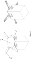
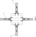
- Each energy dissipater unit comprises an energy dissipater (1) that is in a cylindrical form with enlarged ends which are retained in the diaphragm plate (6) by the lubricated cylindrical second sliding bearing (7), the arm (2) connected to the energy dissipater (1), the sliding block (3) that is connected to the ends of the arms (2) by using an installation shaft (5), a cylindrical first sliding bearing (4) (PTFE) installed between the installation shaft (5) and the sliding block (3), the base plate (8) that is mounted on the bottom part of the energy dissipater (1) and the rail (11) that is clamped to the superstructures such as buildings and tanks through clamping bolts.
- PTFE cylindrical first sliding bearing (4)
- the second sliding bearing (7) special sliding materials with low friction and high strength such as MSM ® or PTFE ® are used.
- the diaphragm plate (6) and the base plate (8) are mounted to the concrete column (12) (substructure) through the first connection plate (9) and the second connection plate 2 (10) on which they are welded.
- the first connection plate (9) is connected to the column at the diaphragm plate (6) level and the second connection plate (10) is connected to the column at the base plate (8) level.
- the rail (11) is formed by a channel shaped rail and three plates that are welded to form the stainless-steel plates bolted to the inner parts of the rails on which the sliding blocks (3) slide on the rails.
- the multidirectional adaptive re-centering torsion isolator is designed to dissipate the energy of the earthquake by flexing of the energy dissipaters (1) during torsion and here the torsion occurs in the single type component of the energy dissipater (1).
- Each energy dissipater (1) is connected to a torsion arm (2) and twists with the rotation of the arm (2).
- the arm (2) is connected to a rail (11) and said rail (11) guides the motion of the arm (2) through the low friction sliding block (3) installed to the end of the arm (2). In this way, the arms (2) are controlled to move along the path pre-defined by the rails (11) regardless of the direction of the displacement exerted on the rail (11) and thus a guided follow-up reel connection is provided.
- the rail (11) is clamped to the superstructure (building, tank etc.) by the clamping bolts.
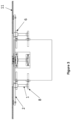
- the energy dissipaters (1) are installed to the column (12) (substructure) through the inside of the diaphragm plate (6) as shown in Figure 5 .
- the diaphragm plate (6) transmits the torsional and fracture forces exerted by the energy dissipaters (1) through the arms (2) on the upper part to the inside of the column (12).
- the single type components of the energy dissipaters (1) are protected against significant torsional and fractural effects and thus almost a single type of torsional flexure is provided.
- a plug type connection (seamless) is used to connect the energy dissipaters (1) to the arms (2) and the base plate (8).
- the energy dissipaters (1) can be easily replaced if they get damaged after a potential earthquake.
- the displacements of the structure (displacement between the sub- and the super-structures) due to earthquake cause displacement of the rails (11) of the multidirectional adaptive re-centering torsion isolator and the rotation of the arms (2) and the torsion of the energy dissipaters (1) are resisted by the energy dissipaters (1) of the multidirectional adaptive re-centering torsion isolator.
- the weight of the structure is supported and transmitted to the columns (12) by the flat articulated slider.
- the distinctive property of the multidirectional adaptive re-centering torsion isolator in force change against the energy dissipater (1) units is the geometrical stiffening behavior.
- the displacements originating from the earthquake are reduced as the result of the geometric stiffening.
- Said property is the result of conversion of the twisting motion to rotation.
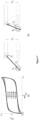
- Figure 6 the bottom operational mechanism of the energy dissipater units of the multidirectional adaptive re-centering torsion isolator which causes the geometric stiffening is shown.
- the mechanism shown in Figure 6 increases the reaction of the force that is required to balance the torsion in the energy dissipaters.
- F max and F Y are the maximum force capacity (the force at D max ) and the effective efficiency force of the multidirectional adaptive re-centering torsion isolator.
Landscapes
- Engineering & Computer Science (AREA)
- Architecture (AREA)
- Environmental & Geological Engineering (AREA)
- Emergency Management (AREA)
- Business, Economics & Management (AREA)
- General Engineering & Computer Science (AREA)
- Civil Engineering (AREA)
- Physics & Mathematics (AREA)
- Structural Engineering (AREA)
- Mechanical Engineering (AREA)
- Aviation & Aerospace Engineering (AREA)
- Acoustics & Sound (AREA)
- Electromagnetism (AREA)
- Buildings Adapted To Withstand Abnormal External Influences (AREA)
- Vibration Prevention Devices (AREA)
Claims (5)
- Isolateur à torsion à recentrage adaptatif multidirectionnel pour placer entre une sous-structure et une superstructure, dans lequel il comprend les suivants ;un coulisseau plat et/ou articulé (13) qui permet la transmission des charges verticales, un faible frottement et une capacité de déplacement horizontal et qui est situé sur le dessus de la colonne (12) de la sous-structure,au moins deux dissipateurs d'énergie cylindriques (1) qui assurent le déplacement, le recentrage et l'amortissement dans toutes les directions horizontales, qui se présentent sous une forme cylindrique avec des extrémités élargies qui sont retenues dans une plaque de diaphragme (6) par des paliers coulissants cylindriques lubrifiés (7) et qui sont installés sur la colonne (12) à l'intérieur de la plaque de diaphragme (6),un bras (2) relié au dissipateur d'énergie (1),un bloc coulissant (3) qui est relié aux extrémités du bras (2) en utilisant un arbre d'installation (5),un premier palier coulissant cylindrique (4) installé entre l'arbre d'installation (5) et le bloc coulissant (3),une plaque de base (8) qui est montée sur la partie inférieure du dissipateur d'énergie (1), une première plaque de connexion (9) qui est reliée à la surface latérale de la colonne au niveau de la plaque de diaphragme (6) et une deuxième plaque de connexion (10) qui est reliée à la surface latérale de la colonne au niveau de la plaque de base (8), etun rail (11) qui est serré aux superstructures telles que les bâtiments et les tanks par des boulons de serrage et qui est relié au bras (2) pour guider le mouvement du bras (2) à travers le bloc coulissant à faible friction (3) installé à l'extrémité du bras (2), dans lequel les bras (2) sont commandés pour se déplacer le long de la trajectoire prédéfinie par les rails (11) quelle que soit la direction du déplacement exercé sur le rail (11).
- Isolateur à torsion à recentrage adaptatif multidirectionnel selon la revendication 1, dans lequel comprenant le rail (11), un rail en forme de canal (11) et trois plaques qui sont soudées pour former les plaques en acier inoxydable boulonnées aux parties intérieures des rails (11) sur lesquelles les blocs coulissants (3) glissent sur les rails.
- Isolateur à torsion à recentrage adaptatif multidirectionnel selon la revendication 1, dans lequel les dissipateurs d'énergie (1) sont reliés aux bras (2) et à la plaque de base (8) par une connexion sans soudure de type bouchon.
- Isolateur à torsion à recentrage adaptatif multidirectionnel selon la revendication 1, dans lequel comprenant quatre ou plus dissipateurs d'énergie (1).
- Procédé de fonctionnement de l'isolateur à torsion à recentrage adaptatif multidirectionnel selon l'une des revendications 1 à 4, caractérisé en ce qu'il comprend les étapes du processus suivantes ;• Relier chaque dissipateur d'énergie (1) à un bras (2) de torsion et tordre par rotation le bras (2),• Relier le bras (2) à un rail (11) afin de convertir le mouvement de rotation du tremblement de terre de la structure en torsion des dissipateurs d'énergie (1) et ledit rail (11) guidant le mouvement du bras (2) à travers le bloc coulissant à faible friction (3) installé à l'extrémité du bras (2),• Commander les bras (2) pour se déplacer le long de la trajectoire prédéfinie par les rails (11) quelle que soit la direction du déplacement exercé sur le rail (11).
Applications Claiming Priority (2)
| Application Number | Priority Date | Filing Date | Title |
|---|---|---|---|
| TR201801822 | 2018-02-09 | ||
| PCT/TR2019/050077 WO2019203766A2 (fr) | 2018-02-09 | 2019-02-07 | Isolateur à torsion à recentrage adaptatif multidirectionnel |
Publications (3)
| Publication Number | Publication Date |
|---|---|
| EP3707322A2 EP3707322A2 (fr) | 2020-09-16 |
| EP3707322A4 EP3707322A4 (fr) | 2021-03-17 |
| EP3707322B1 true EP3707322B1 (fr) | 2025-07-02 |
Family
ID=68240629
Family Applications (1)
| Application Number | Title | Priority Date | Filing Date |
|---|---|---|---|
| EP19788251.7A Active EP3707322B1 (fr) | 2018-02-09 | 2019-02-07 | Isolateur à torsion à recentrage adaptatif multidirectionnel |
Country Status (3)
| Country | Link |
|---|---|
| US (1) | US11384558B2 (fr) |
| EP (1) | EP3707322B1 (fr) |
| WO (1) | WO2019203766A2 (fr) |
Families Citing this family (5)
| Publication number | Priority date | Publication date | Assignee | Title |
|---|---|---|---|---|
| CN113272548B (zh) * | 2018-12-21 | 2024-04-26 | Esm能源及振动控制技术米奇有限公司 | 用于高的细长结构的脉冲振动减振器 |
| CN112854512B (zh) * | 2021-01-12 | 2022-05-17 | 广州大学 | 一种转动型阻尼器 |
| CN114263289A (zh) * | 2022-01-18 | 2022-04-01 | 湖南大学 | 一种具备耗能承载双功能的抗震构件及缓冲器 |
| CN115653380B (zh) * | 2022-12-19 | 2023-03-10 | 中国电建集团山东电力建设第一工程有限公司 | 一种用于输电塔的模块化耗能装配式结构 |
| CN116290405B (zh) * | 2023-05-24 | 2023-09-19 | 四川省第一建筑工程有限公司 | 一种装配式建筑连接装置 |
Family Cites Families (14)
| Publication number | Priority date | Publication date | Assignee | Title |
|---|---|---|---|---|
| CH515430A (de) * | 1970-05-06 | 1971-11-15 | Bbc Brown Boveri & Cie | Vorrichtung zum Einbau zwischen einem mit der Erde verbundenen Fundament und dem Fussteil eines Gerätes zum Fernhalten von mechanischen Stossbewegungen vom Gerät |
| IT1262385B (it) * | 1993-08-03 | 1996-06-19 | Tis Tech Idraulico Stradali | Dispersore di energia meccanico multidirezionale particolarmente adatto per il vincolo di strutture in zona sismica. |
| US5490356A (en) * | 1993-11-24 | 1996-02-13 | Mm Systems Of Arizona | Seismic isolation bearing |
| KR100397141B1 (ko) * | 2000-04-12 | 2003-09-13 | 재단법인서울대학교산학협력재단 | 이중곡률 곡면을 가진 다경간 연속교량의 지진력 분산전달장치 |
| WO2010093337A1 (fr) * | 2009-02-16 | 2010-08-19 | Murat Dicleli | Amortisseur hystérétique de torsion multidirectionnel |
| CN101812879B (zh) | 2010-03-26 | 2012-07-25 | 北京工业大学 | 控制建筑结构三维平动及水平扭转的调谐质量阻尼器及其制作方法 |
| CN205152781U (zh) * | 2015-11-18 | 2016-04-13 | 广州大学 | 一种抗扭支座 |
| CN108412050B (zh) * | 2018-03-29 | 2019-11-29 | 中建联投建设发展有限公司 | 一种落地桁架销轴连接节点结构 |
| CN111851816B (zh) * | 2020-08-21 | 2024-12-20 | 苏州市华丽美登装饰装璜有限公司 | 一种双层幕墙连接结构 |
| CN112065137B (zh) * | 2020-09-15 | 2021-11-30 | 广西贵港建设集团有限公司 | 一种建筑物防震支撑机构 |
| CN112282096B (zh) * | 2020-10-31 | 2024-12-27 | 北京羿射旭科技有限公司 | 一种超低频质量调谐阻尼器 |
| CN112983103A (zh) * | 2021-02-24 | 2021-06-18 | 安徽爱她有果电子商务有限公司 | 一种基于单管通信塔的支撑底座 |
| CN113062487A (zh) * | 2021-03-30 | 2021-07-02 | 温州融宸科技有限公司 | 一种土木工程减震装置及其减震方法 |
| CN112982715B (zh) * | 2021-05-19 | 2021-07-23 | 湖南大学 | 一种基于四杆结构的三维隔震装置 |
-
2019
- 2019-02-07 EP EP19788251.7A patent/EP3707322B1/fr active Active
- 2019-02-07 WO PCT/TR2019/050077 patent/WO2019203766A2/fr not_active Ceased
- 2019-02-07 US US16/771,707 patent/US11384558B2/en active Active
Also Published As
| Publication number | Publication date |
|---|---|
| EP3707322A4 (fr) | 2021-03-17 |
| WO2019203766A2 (fr) | 2019-10-24 |
| EP3707322A2 (fr) | 2020-09-16 |
| US20200392752A1 (en) | 2020-12-17 |
| WO2019203766A3 (fr) | 2020-03-26 |
| US11384558B2 (en) | 2022-07-12 |
Similar Documents
| Publication | Publication Date | Title |
|---|---|---|
| EP3707322B1 (fr) | Isolateur à torsion à recentrage adaptatif multidirectionnel | |
| EP2396479B1 (fr) | Amortisseur hystérétique de torsion multidirectionnel | |
| US20150218839A1 (en) | Seismic isolation mechanism | |
| EP3055464B1 (fr) | Amortisseur d'accouplement de paroi visqueux destiné à être utilisé dans une configuration d'immeuble de stabilisation | |
| JP2016118008A (ja) | 構造物の制振装置、それを用いた上部構造の残留変位を取り除く方法、ならびに橋梁の補強方法 | |
| US4179104A (en) | Mechanical attenuator | |
| KR20120088684A (ko) | 빌딩의 움직임을 감쇠시키는 방법 및 구조체 | |
| US20160222608A1 (en) | Bridge pier structure | |
| KR101868877B1 (ko) | 복원형 댐퍼 및 층간변위억제용 케이블을 이용한 기존건축물의 내진보강 시스템 | |
| US11313145B2 (en) | Earthquake protection systems, methods and apparatus using shape memory alloy (SMA)-based superelasticity-assisted slider (SSS) | |
| WO2009124589A1 (fr) | Paliers agissant comme des dispositifs de dissipation d’énergie | |
| WO2007001103A1 (fr) | Dispositif de protection de pont à poutres utilisant des moyens de sacrifice | |
| JP7228401B2 (ja) | 免震装置 | |
| JP7360519B2 (ja) | 免震構造用ダンパー機構、免震構造用ダンパー機構の配置構造、免震構造用トリガー機構、免震構造用トリガー機構の配置構造、免震構造用すべり支承機構、及び建物 | |
| EP3473847B1 (fr) | Générateur de turbine éolienne | |
| KR20060084173A (ko) | 형상기억합금을 이용한 교량용 면진교좌장치 | |
| CN117107619A (zh) | 一种适用于低净高墩梁的耗能装置及桥梁 | |
| CN220908136U (zh) | 一种多向阻尼索限位减隔震支座 | |
| WO2017204371A1 (fr) | Appareil de maîtrise des vibrations pour structure à faible atténuation | |
| TWI435019B (zh) | Piping support structure | |
| JP7169224B2 (ja) | ダンパー装置 | |
| JP7520689B2 (ja) | ダンパー構造 | |
| CN216664495U (zh) | 一种水平刚度可调分离式组合隔震装置 | |
| Şcheaua | Mechanical Systems based on Dry Friction Force used for Building Isolation against Seismic Actions | |
| Park et al. | Energy Dissipation Capacity of Friction-Type Reinforcing Members Installed at a Transmission Tower |
Legal Events
| Date | Code | Title | Description |
|---|---|---|---|
| STAA | Information on the status of an ep patent application or granted ep patent |
Free format text: STATUS: THE INTERNATIONAL PUBLICATION HAS BEEN MADE |
|
| PUAI | Public reference made under article 153(3) epc to a published international application that has entered the european phase |
Free format text: ORIGINAL CODE: 0009012 |
|
| STAA | Information on the status of an ep patent application or granted ep patent |
Free format text: STATUS: REQUEST FOR EXAMINATION WAS MADE |
|
| 17P | Request for examination filed |
Effective date: 20200609 |
|
| AK | Designated contracting states |
Kind code of ref document: A2 Designated state(s): AL AT BE BG CH CY CZ DE DK EE ES FI FR GB GR HR HU IE IS IT LI LT LU LV MC MK MT NL NO PL PT RO RS SE SI SK SM TR |
|
| AX | Request for extension of the european patent |
Extension state: BA ME |
|
| A4 | Supplementary search report drawn up and despatched |
Effective date: 20210211 |
|
| RIC1 | Information provided on ipc code assigned before grant |
Ipc: E04B 1/98 20060101ALI20210205BHEP Ipc: E04H 9/02 20060101ALI20210205BHEP Ipc: E04H 9/00 20060101AFI20210205BHEP |
|
| DAV | Request for validation of the european patent (deleted) | ||
| DAX | Request for extension of the european patent (deleted) | ||
| STAA | Information on the status of an ep patent application or granted ep patent |
Free format text: STATUS: EXAMINATION IS IN PROGRESS |
|
| 17Q | First examination report despatched |
Effective date: 20230717 |
|
| GRAP | Despatch of communication of intention to grant a patent |
Free format text: ORIGINAL CODE: EPIDOSNIGR1 |
|
| STAA | Information on the status of an ep patent application or granted ep patent |
Free format text: STATUS: GRANT OF PATENT IS INTENDED |
|
| INTG | Intention to grant announced |
Effective date: 20250103 |
|
| GRAS | Grant fee paid |
Free format text: ORIGINAL CODE: EPIDOSNIGR3 |
|
| GRAA | (expected) grant |
Free format text: ORIGINAL CODE: 0009210 |
|
| STAA | Information on the status of an ep patent application or granted ep patent |
Free format text: STATUS: THE PATENT HAS BEEN GRANTED |
|
| AK | Designated contracting states |
Kind code of ref document: B1 Designated state(s): AL AT BE BG CH CY CZ DE DK EE ES FI FR GB GR HR HU IE IS IT LI LT LU LV MC MK MT NL NO PL PT RO RS SE SI SK SM TR |
|
| REG | Reference to a national code |
Ref country code: GB Ref legal event code: FG4D |
|
| REG | Reference to a national code |
Ref country code: CH Ref legal event code: EP |
|
| REG | Reference to a national code |
Ref country code: DE Ref legal event code: R096 Ref document number: 602019071977 Country of ref document: DE |
|
| REG | Reference to a national code |
Ref country code: IE Ref legal event code: FG4D |
|
| REG | Reference to a national code |
Ref country code: NL Ref legal event code: MP Effective date: 20250702 |
|
| PG25 | Lapsed in a contracting state [announced via postgrant information from national office to epo] |
Ref country code: PT Free format text: LAPSE BECAUSE OF FAILURE TO SUBMIT A TRANSLATION OF THE DESCRIPTION OR TO PAY THE FEE WITHIN THE PRESCRIBED TIME-LIMIT Effective date: 20251103 |
|
| PG25 | Lapsed in a contracting state [announced via postgrant information from national office to epo] |
Ref country code: NL Free format text: LAPSE BECAUSE OF FAILURE TO SUBMIT A TRANSLATION OF THE DESCRIPTION OR TO PAY THE FEE WITHIN THE PRESCRIBED TIME-LIMIT Effective date: 20250702 |
|
| REG | Reference to a national code |
Ref country code: AT Ref legal event code: MK05 Ref document number: 1809415 Country of ref document: AT Kind code of ref document: T Effective date: 20250702 |
|
| PG25 | Lapsed in a contracting state [announced via postgrant information from national office to epo] |
Ref country code: IS Free format text: LAPSE BECAUSE OF FAILURE TO SUBMIT A TRANSLATION OF THE DESCRIPTION OR TO PAY THE FEE WITHIN THE PRESCRIBED TIME-LIMIT Effective date: 20251102 |
|
| PG25 | Lapsed in a contracting state [announced via postgrant information from national office to epo] |
Ref country code: NO Free format text: LAPSE BECAUSE OF FAILURE TO SUBMIT A TRANSLATION OF THE DESCRIPTION OR TO PAY THE FEE WITHIN THE PRESCRIBED TIME-LIMIT Effective date: 20251002 |
|
| REG | Reference to a national code |
Ref country code: LT Ref legal event code: MG9D |
|
| PG25 | Lapsed in a contracting state [announced via postgrant information from national office to epo] |
Ref country code: AT Free format text: LAPSE BECAUSE OF FAILURE TO SUBMIT A TRANSLATION OF THE DESCRIPTION OR TO PAY THE FEE WITHIN THE PRESCRIBED TIME-LIMIT Effective date: 20250702 |
|
| PG25 | Lapsed in a contracting state [announced via postgrant information from national office to epo] |
Ref country code: FI Free format text: LAPSE BECAUSE OF FAILURE TO SUBMIT A TRANSLATION OF THE DESCRIPTION OR TO PAY THE FEE WITHIN THE PRESCRIBED TIME-LIMIT Effective date: 20250702 |
|
| PG25 | Lapsed in a contracting state [announced via postgrant information from national office to epo] |
Ref country code: HR Free format text: LAPSE BECAUSE OF FAILURE TO SUBMIT A TRANSLATION OF THE DESCRIPTION OR TO PAY THE FEE WITHIN THE PRESCRIBED TIME-LIMIT Effective date: 20250702 |
|
| PG25 | Lapsed in a contracting state [announced via postgrant information from national office to epo] |
Ref country code: GR Free format text: LAPSE BECAUSE OF FAILURE TO SUBMIT A TRANSLATION OF THE DESCRIPTION OR TO PAY THE FEE WITHIN THE PRESCRIBED TIME-LIMIT Effective date: 20251003 |
|
| PG25 | Lapsed in a contracting state [announced via postgrant information from national office to epo] |
Ref country code: SE Free format text: LAPSE BECAUSE OF FAILURE TO SUBMIT A TRANSLATION OF THE DESCRIPTION OR TO PAY THE FEE WITHIN THE PRESCRIBED TIME-LIMIT Effective date: 20250702 Ref country code: CZ Free format text: LAPSE BECAUSE OF FAILURE TO SUBMIT A TRANSLATION OF THE DESCRIPTION OR TO PAY THE FEE WITHIN THE PRESCRIBED TIME-LIMIT Effective date: 20250702 |
|
| PG25 | Lapsed in a contracting state [announced via postgrant information from national office to epo] |
Ref country code: LV Free format text: LAPSE BECAUSE OF FAILURE TO SUBMIT A TRANSLATION OF THE DESCRIPTION OR TO PAY THE FEE WITHIN THE PRESCRIBED TIME-LIMIT Effective date: 20250702 |
|
| PG25 | Lapsed in a contracting state [announced via postgrant information from national office to epo] |
Ref country code: PL Free format text: LAPSE BECAUSE OF FAILURE TO SUBMIT A TRANSLATION OF THE DESCRIPTION OR TO PAY THE FEE WITHIN THE PRESCRIBED TIME-LIMIT Effective date: 20250702 Ref country code: BG Free format text: LAPSE BECAUSE OF FAILURE TO SUBMIT A TRANSLATION OF THE DESCRIPTION OR TO PAY THE FEE WITHIN THE PRESCRIBED TIME-LIMIT Effective date: 20250702 |
|
| PG25 | Lapsed in a contracting state [announced via postgrant information from national office to epo] |
Ref country code: RS Free format text: LAPSE BECAUSE OF FAILURE TO SUBMIT A TRANSLATION OF THE DESCRIPTION OR TO PAY THE FEE WITHIN THE PRESCRIBED TIME-LIMIT Effective date: 20251002 |
|
| PG25 | Lapsed in a contracting state [announced via postgrant information from national office to epo] |
Ref country code: ES Free format text: LAPSE BECAUSE OF FAILURE TO SUBMIT A TRANSLATION OF THE DESCRIPTION OR TO PAY THE FEE WITHIN THE PRESCRIBED TIME-LIMIT Effective date: 20250702 |
|
| PG25 | Lapsed in a contracting state [announced via postgrant information from national office to epo] |
Ref country code: SM Free format text: LAPSE BECAUSE OF FAILURE TO SUBMIT A TRANSLATION OF THE DESCRIPTION OR TO PAY THE FEE WITHIN THE PRESCRIBED TIME-LIMIT Effective date: 20250702 |
|
| PG25 | Lapsed in a contracting state [announced via postgrant information from national office to epo] |
Ref country code: DK Free format text: LAPSE BECAUSE OF FAILURE TO SUBMIT A TRANSLATION OF THE DESCRIPTION OR TO PAY THE FEE WITHIN THE PRESCRIBED TIME-LIMIT Effective date: 20250702 |
|
| PGFP | Annual fee paid to national office [announced via postgrant information from national office to epo] |
Ref country code: DE Payment date: 20260227 Year of fee payment: 8 |
|
| PG25 | Lapsed in a contracting state [announced via postgrant information from national office to epo] |
Ref country code: IT Free format text: LAPSE BECAUSE OF FAILURE TO SUBMIT A TRANSLATION OF THE DESCRIPTION OR TO PAY THE FEE WITHIN THE PRESCRIBED TIME-LIMIT Effective date: 20250702 |
|
| PGFP | Annual fee paid to national office [announced via postgrant information from national office to epo] |
Ref country code: FR Payment date: 20260227 Year of fee payment: 8 |
|
| PG25 | Lapsed in a contracting state [announced via postgrant information from national office to epo] |
Ref country code: SK Free format text: LAPSE BECAUSE OF FAILURE TO SUBMIT A TRANSLATION OF THE DESCRIPTION OR TO PAY THE FEE WITHIN THE PRESCRIBED TIME-LIMIT Effective date: 20250702 Ref country code: EE Free format text: LAPSE BECAUSE OF FAILURE TO SUBMIT A TRANSLATION OF THE DESCRIPTION OR TO PAY THE FEE WITHIN THE PRESCRIBED TIME-LIMIT Effective date: 20250702 |