EP3708787A1 - Plug in fluid cooled electrical connections for tail cone mounted generator - Google Patents
Plug in fluid cooled electrical connections for tail cone mounted generator Download PDFInfo
- Publication number
- EP3708787A1 EP3708787A1 EP19211842.0A EP19211842A EP3708787A1 EP 3708787 A1 EP3708787 A1 EP 3708787A1 EP 19211842 A EP19211842 A EP 19211842A EP 3708787 A1 EP3708787 A1 EP 3708787A1
- Authority
- EP
- European Patent Office
- Prior art keywords
- coolant
- conveying tube
- opening
- electric generator
- gas turbine
- Prior art date
- Legal status (The legal status is an assumption and is not a legal conclusion. Google has not performed a legal analysis and makes no representation as to the accuracy of the status listed.)
- Granted
Links
Images



Classifications
-
- F—MECHANICAL ENGINEERING; LIGHTING; HEATING; WEAPONS; BLASTING
- F01—MACHINES OR ENGINES IN GENERAL; ENGINE PLANTS IN GENERAL; STEAM ENGINES
- F01D—NON-POSITIVE DISPLACEMENT MACHINES OR ENGINES, e.g. STEAM TURBINES
- F01D15/00—Adaptations of machines or engines for special use; Combinations of engines with devices driven thereby
- F01D15/10—Adaptations for driving, or combinations with, electric generators
-
- B—PERFORMING OPERATIONS; TRANSPORTING
- B64—AIRCRAFT; AVIATION; COSMONAUTICS
- B64D—EQUIPMENT FOR FITTING IN OR TO AIRCRAFT; FLIGHT SUITS; PARACHUTES; ARRANGEMENT OR MOUNTING OF POWER PLANTS OR PROPULSION TRANSMISSIONS IN AIRCRAFT
- B64D27/00—Arrangement or mounting of power plants in aircraft; Aircraft characterised by the type or position of power plants
- B64D27/02—Aircraft characterised by the type or position of power plants
- B64D27/10—Aircraft characterised by the type or position of power plants of gas-turbine type
-
- B—PERFORMING OPERATIONS; TRANSPORTING
- B64—AIRCRAFT; AVIATION; COSMONAUTICS
- B64D—EQUIPMENT FOR FITTING IN OR TO AIRCRAFT; FLIGHT SUITS; PARACHUTES; ARRANGEMENT OR MOUNTING OF POWER PLANTS OR PROPULSION TRANSMISSIONS IN AIRCRAFT
- B64D33/00—Arrangement in aircraft of power plant parts or auxiliaries not otherwise provided for
- B64D33/08—Arrangement in aircraft of power plant parts or auxiliaries not otherwise provided for of power plant cooling systems
-
- F—MECHANICAL ENGINEERING; LIGHTING; HEATING; WEAPONS; BLASTING
- F01—MACHINES OR ENGINES IN GENERAL; ENGINE PLANTS IN GENERAL; STEAM ENGINES
- F01D—NON-POSITIVE DISPLACEMENT MACHINES OR ENGINES, e.g. STEAM TURBINES
- F01D25/00—Component parts, details, or accessories, not provided for in, or of interest apart from, other groups
- F01D25/08—Cooling; Heating; Heat-insulation
- F01D25/12—Cooling
-
- F—MECHANICAL ENGINEERING; LIGHTING; HEATING; WEAPONS; BLASTING
- F01—MACHINES OR ENGINES IN GENERAL; ENGINE PLANTS IN GENERAL; STEAM ENGINES
- F01D—NON-POSITIVE DISPLACEMENT MACHINES OR ENGINES, e.g. STEAM TURBINES
- F01D25/00—Component parts, details, or accessories, not provided for in, or of interest apart from, other groups
- F01D25/30—Exhaust heads, chambers, or the like
-
- F—MECHANICAL ENGINEERING; LIGHTING; HEATING; WEAPONS; BLASTING
- F02—COMBUSTION ENGINES; HOT-GAS OR COMBUSTION-PRODUCT ENGINE PLANTS
- F02C—GAS-TURBINE PLANTS; AIR INTAKES FOR JET-PROPULSION PLANTS; CONTROLLING FUEL SUPPLY IN AIR-BREATHING JET-PROPULSION PLANTS
- F02C7/00—Features, components parts, details or accessories, not provided for in, or of interest apart form groups F02C1/00 - F02C6/00; Air intakes for jet-propulsion plants
- F02C7/12—Cooling of plants
- F02C7/16—Cooling of plants characterised by cooling medium
- F02C7/18—Cooling of plants characterised by cooling medium the medium being gaseous, e.g. air
-
- F—MECHANICAL ENGINEERING; LIGHTING; HEATING; WEAPONS; BLASTING
- F02—COMBUSTION ENGINES; HOT-GAS OR COMBUSTION-PRODUCT ENGINE PLANTS
- F02C—GAS-TURBINE PLANTS; AIR INTAKES FOR JET-PROPULSION PLANTS; CONTROLLING FUEL SUPPLY IN AIR-BREATHING JET-PROPULSION PLANTS
- F02C7/00—Features, components parts, details or accessories, not provided for in, or of interest apart form groups F02C1/00 - F02C6/00; Air intakes for jet-propulsion plants
- F02C7/32—Arrangement, mounting, or driving, of auxiliaries
-
- F—MECHANICAL ENGINEERING; LIGHTING; HEATING; WEAPONS; BLASTING
- F02—COMBUSTION ENGINES; HOT-GAS OR COMBUSTION-PRODUCT ENGINE PLANTS
- F02K—JET-PROPULSION PLANTS
- F02K3/00—Plants including a gas turbine driving a compressor or a ducted fan
- F02K3/02—Plants including a gas turbine driving a compressor or a ducted fan in which part of the working fluid by-passes the turbine and combustion chamber
- F02K3/04—Plants including a gas turbine driving a compressor or a ducted fan in which part of the working fluid by-passes the turbine and combustion chamber the plant including ducted fans, i.e. fans with high volume, low pressure outputs, for augmenting the jet thrust, e.g. of double-flow type
- F02K3/065—Plants including a gas turbine driving a compressor or a ducted fan in which part of the working fluid by-passes the turbine and combustion chamber the plant including ducted fans, i.e. fans with high volume, low pressure outputs, for augmenting the jet thrust, e.g. of double-flow type with front and aft fans
-
- H—ELECTRICITY
- H02—GENERATION; CONVERSION OR DISTRIBUTION OF ELECTRIC POWER
- H02K—DYNAMO-ELECTRIC MACHINES
- H02K7/00—Arrangements for handling mechanical energy structurally associated with dynamo-electric machines, e.g. structural association with mechanical driving motors or auxiliary dynamo-electric machines
- H02K7/18—Structural association of electric generators with mechanical driving motors, e.g. with turbines
- H02K7/1807—Rotary generators
- H02K7/1823—Rotary generators structurally associated with turbines or similar engines
-
- H—ELECTRICITY
- H02—GENERATION; CONVERSION OR DISTRIBUTION OF ELECTRIC POWER
- H02K—DYNAMO-ELECTRIC MACHINES
- H02K9/00—Arrangements for cooling or ventilating
- H02K9/19—Arrangements for cooling or ventilating for machines with closed casing and closed-circuit cooling using a liquid cooling medium, e.g. oil
-
- F—MECHANICAL ENGINEERING; LIGHTING; HEATING; WEAPONS; BLASTING
- F05—INDEXING SCHEMES RELATING TO ENGINES OR PUMPS IN VARIOUS SUBCLASSES OF CLASSES F01-F04
- F05D—INDEXING SCHEME FOR ASPECTS RELATING TO NON-POSITIVE-DISPLACEMENT MACHINES OR ENGINES, GAS-TURBINES OR JET-PROPULSION PLANTS
- F05D2220/00—Application
- F05D2220/30—Application in turbines
- F05D2220/32—Application in turbines in gas turbines
- F05D2220/323—Application in turbines in gas turbines for aircraft propulsion, e.g. jet engines
-
- F—MECHANICAL ENGINEERING; LIGHTING; HEATING; WEAPONS; BLASTING
- F05—INDEXING SCHEMES RELATING TO ENGINES OR PUMPS IN VARIOUS SUBCLASSES OF CLASSES F01-F04
- F05D—INDEXING SCHEME FOR ASPECTS RELATING TO NON-POSITIVE-DISPLACEMENT MACHINES OR ENGINES, GAS-TURBINES OR JET-PROPULSION PLANTS
- F05D2220/00—Application
- F05D2220/50—Application for auxiliary power units (APU's)
-
- F—MECHANICAL ENGINEERING; LIGHTING; HEATING; WEAPONS; BLASTING
- F05—INDEXING SCHEMES RELATING TO ENGINES OR PUMPS IN VARIOUS SUBCLASSES OF CLASSES F01-F04
- F05D—INDEXING SCHEME FOR ASPECTS RELATING TO NON-POSITIVE-DISPLACEMENT MACHINES OR ENGINES, GAS-TURBINES OR JET-PROPULSION PLANTS
- F05D2220/00—Application
- F05D2220/70—Application in combination with
- F05D2220/76—Application in combination with an electrical generator
-
- F—MECHANICAL ENGINEERING; LIGHTING; HEATING; WEAPONS; BLASTING
- F05—INDEXING SCHEMES RELATING TO ENGINES OR PUMPS IN VARIOUS SUBCLASSES OF CLASSES F01-F04
- F05D—INDEXING SCHEME FOR ASPECTS RELATING TO NON-POSITIVE-DISPLACEMENT MACHINES OR ENGINES, GAS-TURBINES OR JET-PROPULSION PLANTS
- F05D2260/00—Function
- F05D2260/20—Heat transfer, e.g. cooling
- F05D2260/213—Heat transfer, e.g. cooling by the provision of a heat exchanger within the cooling circuit
-
- Y—GENERAL TAGGING OF NEW TECHNOLOGICAL DEVELOPMENTS; GENERAL TAGGING OF CROSS-SECTIONAL TECHNOLOGIES SPANNING OVER SEVERAL SECTIONS OF THE IPC; TECHNICAL SUBJECTS COVERED BY FORMER USPC CROSS-REFERENCE ART COLLECTIONS [XRACs] AND DIGESTS
- Y02—TECHNOLOGIES OR APPLICATIONS FOR MITIGATION OR ADAPTATION AGAINST CLIMATE CHANGE
- Y02T—CLIMATE CHANGE MITIGATION TECHNOLOGIES RELATED TO TRANSPORTATION
- Y02T50/00—Aeronautics or air transport
- Y02T50/60—Efficient propulsion technologies, e.g. for aircraft
Definitions
- the subject matter disclosed herein generally relates to gas turbine engines, and more specifically to electrical generators for gas turbine engines.
- a gas turbine engine including: a tail cone; a low pressure compressor; a low pressure turbine; a low speed spool interconnecting the low pressure compressor and the low pressure turbine; and an electric generator located within the tail cone, the electric generator being operably connected to the low speed spool, wherein the electric generator includes a coolant cavity in thermal communication with one or more components of the electric generator; a structural support housing at least partially enclosing the electric generator, the structural support housing including a forward wall located on a forward end of the structural support housing, wherein the forward wall includes a first opening; a first coolant conveying tube extending through the first opening to fluidly connect to the coolant cavity; and a first electrical connector tube extending through the first opening within the first coolant conveying tube to electrically connect to the electric generator.
- further embodiments may include that the forward wall further includes at a second opening and the gas turbine engine further includes: a second coolant conveying tube extending through the second opening to fluidly connect to the coolant cavity; and a second electrical connector tube extending through the second opening within the second coolant conveying tube to electrically connect to the electric generator.
- further embodiments may include that the first coolant conveying tube is operable to supply coolant to the coolant cavity.
- further embodiments may include that the first coolant conveying tube is operable to supply coolant to the coolant cavity.
- further embodiments may include that the second coolant conveying tube is operable to remove coolant from the coolant cavity.
- further embodiments may include that the second coolant conveying tube is operable to remove coolant from the coolant cavity.
- further embodiments may include that the first opening is located gravitationally above the second opening.
- further embodiments may include: a heat rejection heat exchanger fluidly connected to the first coolant conveying tube and the second coolant conveying tube.
- further embodiments may include: a bypass duct, wherein the heat rejection heat exchanger is in thermal communication with the bypass duct.
- further embodiments may include a bypass duct, wherein the heat rejection heat exchanger is located within the bypass duct.
- an electric generation system for a gas turbine engine including: a tail cone; an electric generator located within the tail cone, the electric generator including a coolant cavity in thermal communication with one or more components of the electric generator; a structural support housing at least partially enclosing the electric generator, the structural support housing including a forward wall located on a forward end of the structural support housing, wherein the forward wall includes a first opening; a first coolant conveying tube extending through the first opening to fluidly connect to the coolant cavity; and a first electrical connector tube extending through the first opening within the first coolant conveying tube to electrically connect to the electric generator.
- further embodiments may include that the forward wall further includes at a second opening and the electric generation system further includes: a second coolant conveying tube extending through the second opening to fluidly connect to the coolant cavity; and a second electrical connector tube extending through the second opening within the second coolant conveying tube to electrically connect to the electric generator.
- further embodiments may include that the first coolant conveying tube is operable to supply coolant to the coolant cavity.
- further embodiments may include that the first coolant conveying tube is operable to supply coolant to the coolant cavity.
- further embodiments may include that the second coolant conveying tube is operable to remove coolant from the coolant cavity.
- further embodiments may include that the second coolant conveying tube is operable to remove coolant from the coolant cavity.
- further embodiments may include that the first opening is located gravitationally above the second opening.
- further embodiments may include a heat rejection heat exchanger fluidly connected to the first coolant conveying tube and the second coolant conveying tube.
- further embodiments may include that the electric generator is configured to connect to a low speed spool of the gas turbine engine.
- High pressure spools of gas turbine engines may be used to drive accessories of the gas turbine engine.
- Engine bypass ratios increase, the capability of a high pressure spool to drive accessories, such as electric generators, has been diminished. Therefore it is desirable to drive accessories off of a low pressure spool of the gas turbine engine.
- Gas turbine engines typically drive accessories through a radial tower shaft and accessory gearbox operably connected to the high pressure spool, however connecting to the low pressure spool is more challenging.
- Gas turbines may also include a tail cone at the rear of the engine to help accelerate the exhaust flow and create additional thrust.
- the enclosed area within this tail cone is typically empty space, and is also adjacent to the rotating low pressure spool.
- Embodiments disclosed herein seek to take advantage of this empty space by locating an electric generator within the tail cone and operably connecting the electric generator to the low speed spool such that the electric generator is driven by the low speed spool.
- High temperatures within the area of the tail cone complicate locating a generator within the tail cone and therefore embodiments disclosed herein also seek to address the challenges of locating the generator within the potentially high temperature environment of the tail cone.
- FIG. 1 schematically illustrates an example gas turbine engine 20 that may incorporate embodiments of the present disclosure.
- the gas turbine engine 20 is disclosed herein as a two-spool turbofan that generally incorporates a fan section 22, a compressor section 24, a combustor section 26 and a turbine section 28.
- Alternative engines might include an augmentor section (not shown) among other systems or features.
- the fan section 22 drives air along a bypass flow path B in a bypass duct, while the compressor section 24 drives air along a core flow path C for compression and communication into the combustor section 26 then expansion through the turbine section 28.
- the exemplary engine 20 generally includes a low speed spool 30 and a high speed spool 32 mounted for rotation about an engine central longitudinal axis A relative to an engine static structure 36 via several bearing systems 38. It should be understood that various bearing systems 38 at various locations may alternatively or additionally be provided, and the location of bearing systems 38 may be varied as appropriate to the application.
- the low speed spool 30 generally includes an inner shaft 40 that interconnects a fan 42, a low pressure compressor 44 and a low pressure turbine 46.
- the fan 42 may be driven at a lower speed than the low speed spool 30.
- the high speed spool 32 includes an outer shaft 50 that interconnects a high pressure compressor 52 and high pressure turbine 54.
- a combustor 56 is arranged in exemplary gas turbine 20 between the high pressure compressor 52 and the high pressure turbine 54.
- An engine static structure 36 is arranged generally between the high pressure turbine 54 and the low pressure turbine 46.
- the engine static structure 36 further supports bearing systems 38 in the turbine section 28.
- the inner shaft 40 and the outer shaft 50 are concentric and rotate via bearing systems 38 about the engine central longitudinal axis A, which is collinear with their longitudinal axes.
- the core airflow is compressed by the low pressure compressor 44 then the high pressure compressor 52, mixed and burned with fuel in the combustor 56, then expanded over the high pressure turbine 54 and low pressure turbine 46.
- the turbine section 28 rotationally drives the respective low speed spool 30 and high speed spool 32 in response to the expansion. It will be appreciated that each of the positions of the fan section 22, compressor section 24, combustor section 26, and turbine section 28, may be varied.
- the engine 20 in one example is a high-bypass geared aircraft engine.
- the engine 20 bypass ratio is greater than about six (6), with an example embodiment being greater than about ten (10).
- the engine 20 bypass ratio is greater than about ten (10:1)
- the fan diameter is significantly larger than that of the low pressure compressor 44
- the low pressure turbine 46 has a pressure ratio that is greater than about five 5:1.
- Low pressure turbine 46 pressure ratio is pressure measured prior to inlet of low pressure turbine 46 as related to the pressure at the outlet of the low pressure turbine 46 prior to an exhaust nozzle. A significant amount of thrust is provided by the bypass flow B due to the high bypass ratio.
- the engine 20 includes a tail cone 100 located on a rear portion of the engine 20.
- the tail cone 100 is operably shaped to help accelerate the exhaust air flow exiting the core flow path C and create additional thrust for the engine 20.
- the tail cone 100 may be securely fastened to the engine 20 via a plurality of fasteners 110 to a structural portion of the engine 20.
- the structural portion of the gas turbine engine 20 may be the engine static structure 36.
- the plurality of fasteners 110 may be arranged circumferentially around the engine central longitudinal axis A.
- the tail cone 100 may be securely fastened to the engine 20 in a cantilevered arrangement, as shown in FIG. 1 .
- the tail cone 100 includes a hollow interior space 120 within the tail cone 100. Conventional gas turbine engines typically leave this interior space empty and unused, however embodiments disclosed herein seek to utilize this interior space 120 by locating an electric generator within the interior space 120, as discussed further herein.
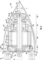
- FIG. 2 a cross-section view of an electric generator 200 located within the interior space 120 of the tail cone 100 is illustrated, in accordance with an embodiment of the present disclosure.
- the combination of the electric generator 200 and the tail cone 100 may be considered an electric generation system 80 for the gas turbine engine 20 of FIG. 1 .
- the electric generator 200 may be operably connected to the low speed spool 30 of the engine 20.
- a drive shaft coupling 202 may operably connect a shaft 210 of the electric generator 200 to the low speed spool 30.
- the low speed spool 30 is configured to rotate the shaft 210 of the electric generator 200 and the electric generator 200 is configured to generate electricity in response to the rotation of the shaft 210.
- the electricity generated by the electric generator 200 may be provided to the engine 20 and/or the aircraft to power various electrical devices.
- the electric generator 200 may be a three-stage electrical generator that includes a main generator 220, an exciter generator 240, and a permanent magnet generator 260. It is understood that while a three-stage wound field synchronous electrical generator 200 is illustrated, the embodiments disclosed herein may be applied to other electrical generators including but not limited to a permanent magnet electrical generator, an induction electrical generator, a switched reluctance electrical generator, or any other electrical generator known to one of skill in the art.
- the main generator 220, the exciter generator 240, and the permanent magnet generator 260 may each be brushless.
- the main generator 220 includes a main field winding 224 on a rotating portion 222 and a generator armature winding 228 of a stationary portion 226.
- the exciter generator 240 includes a rotating exciter armature winding 244 on a rotating portion 242 and an exciter winding 248 on a stationary portion 246.
- the permanent magnet generator 260 includes permanent magnets 264 employed on a rotating portion 262 and a winding 268 on a stator portion 266.
- the rotating portion 222 of the main generator 220, the rotating portion 242 of the exciter generator 240, and the rotating portion 262 of the permanent magnet generator 260 may each be operably connected to the shaft 210 of the electric generator 200 and configured to rotate with the shaft 210 around the engine central longitudinal axis A.
- the rotation of permanent magnets 264 generates an alternating current voltage on windings 268 of the stator portion 266.
- the AC voltage provided by the permanent magnet generator 260 is rectified and selectively applied to an exciter winding 248 on a stationary portion 246 of the exciter generator 240.
- the exciter winding 248 generates a field that interacts with rotating exciter armature windings 244 on a rotating portion 242 of the exciter generator 240 to provide an AC voltage.
- a rotating rectifier assembly 250 rectifies the AC voltage and supplies the DC voltage to a main field winding 224 on the rotating portion 222 of the main generator 220.
- the rotating portion 224 may be operably connected to the low speed spool 30 through the shaft 210 and configured to rotate when the low speed spool 30 rotates. Rotation of the shaft 210 and the main field winding 224 induces three-phase AC output voltage on the generator armature winding 228 of the stationary portion 226 of the main generator 220.
- the electric generator 200 is incased in a structural support housing 280 that provides structure support for the electric generator 200.
- the structural support housing 280 may be securely attached to a support structure (e.g., the engine static structure 36) of the gas turbine engine 20.
- the structural support housing 280 may be securely fastened to the engine 20 in a cantilevered arrangement, as shown in FIG. 1 .
- the structural support housing 280 may at least partially enclose the electric generator 200.
- the structural support housing 280 may fully enclose the electric generator 200 with the exception of the drive shaft coupling 202 extending through the structural support housing 280 to connect to the low speed spool 30.
- the electric generator 200 may include electrical connectors. Electric generators may utilize electrical connectors that extend radially outward from the engine central longitudinal axis A in about the R1 direction. However this electrical connector arrangement may not work for the electrical generator 200 illustrated in FIG. 2 because extending electrical connectors radially outward from the engine central longitudinal axis A in about the R1 direction would place the electrical connectors in an area either proximate the tail cone 100 or through the tail cone 100, which may see elevated temperatures during operation of the engine 20. Embodiments disclosed herein seek to protect the electrical connectors of the electric generator 200 from these elevated temperatures. Electrical connectors 302, 304 (see FIG. 3 ) may protrude through a forward wall 282 of the structural support housing 280. The forward wall 282 is located on a forward end 285 of the structural support housing 280. The forward end 285 is opposite an aft end 289.
- the forward wall 282 may include a coupling opening 288, a first opening 284, and a second opening 286.
- the first opening 284 may be located gravitationally above the second opening 286.
- the drive shaft coupling 202 may extend through the coupling opening 288.
- a first coolant conveying tube 322 may extend through the first opening 284 and fluidly connect to the coolant cavity 300.
- the first coolant conveying tube 322 may be operable to supply coolant (e.g., cooled coolant) to a coolant cavity 300 of the electric generator 200 from a 434 of a heat exchanger system 400.
- the coolant cavity 300 may be in thermal communication with one or more components of the electric generator 200 that require heat removal, such as, for example, the main generator 220, the exciter generator 240, and the permanent magnet generator 260.
- the electric generator 200 may include one or more coolant cavities 300 that are enclosed within the electric generator 200.
- the coolant may be oil.
- a second coolant conveying tube 324 may extend through the second opening 286. The second coolant conveying tube 324 may be operable to remove coolant (e.g., heated coolant) from the coolant cavity 300 the electric generator 200 and convey the heated coolant to the heat rejection heat exchanger 434 of the heat exchanger system 400.
- a first electrical connector 302 extends through the first opening 284 within the first coolant conveying tube 322 to electrically connect to the electric generator 200.
- the first electrical connector 302 electrically connects the electrical generator 200 to components of the engine 20 or aircraft outside of the tail cone 100 that may require electricity from the electrical generator 200.
- the first electrical connector 302 is electrically connected to the main generator 220, the exciter generator 240, and the permanent magnet generator 260.
- the first electrical connector 302 is immersed in coolant by passing through the first coolant conveying tube 322.
- the coolant within the first coolant conveying tube 322 helps protect the first electrical connector 302 from elevated temperatures proximate the tail cone 100.
- the first electrical connector 302 may include a shield (not shown) to protect against the coolant.
- a second electrical connector 304 extends through the second opening 286 within the second coolant conveying tube 324 to electrically connect to the electric generator 200.
- the second electrical connector 304 electrically connects the electrical generator 200 to components of the engine 20 or aircraft outside of the tail cone 100 that may require electricity from the electrical generator 200.
- the second electrical connector 304 is electrically connected to the main generator 220, the exciter generator 240, and the permanent magnet generator 260.
- the second electrical connector 304 is immersed in coolant by passing through the second coolant conveying tube 324.
- the coolant within the second coolant conveying tube 324 helps protect the second electrical connector 304 from elevated temperatures proximate the tail cone 100.
- the second electrical connector 304 may include a shield (not shown) to protect against the coolant.
- the heat exchanger system 400 removes heat from the electrical generator 200.
- the heat exchanger system 400 may include at least one of a coolant pump 432, a heat rejection heat exchanger 434, and the coolant cavity 300 (i.e., heat absorption heat exchanger or evaporator) connected in fluid communication in a closed loop coolant circuit 430.
- the coolant cavity 300 may operate as a heat absorption heat exchanger of the heat exchanger system 400.
- the coolant used in the coolant circuit 430 may be an oil. It is to be understood that other components (not shown) may be incorporated into the coolant circuit 430 as desired.
- Coolant may enter the coolant cavity 300 through the first coolant conveying tube 322 and exit the coolant cavity 300 through the out coolant conveying tube 324.
- the first electrical connector 302 may enter the electrical generator 200 through the first coolant conveying tube 322 and the second electrical connector 304 may exit the electrical generator 200 through the second coolant conveying tube 324.
- the heat rejection heat exchanger 434 may operate to reject heat from the coolant circuit 432 that was absorbed by the coolant cavity 300.
- the heat rejection heat exchanger 434 may be in thermal communication with the bypass duct 42 of the engine 20.
- the heat rejection heat exchanger 434 may be located within the bypass duct 42 of the engine 20. Bypass air flowing through the bypass duct 42 may be used to absorb heat from the heat rejection heat exchanger 434.
- the heat absorption heat exchanger 434 may, for example, also comprise one or more coolant conveying coiled tubes or one or more tube banks formed of a plurality of coolant conveying tubes extending between respective inlet and outlet manifolds.
- the coolant pump 432 may comprise a single-stage or multiple-stage compressor such as, for example, a reciprocating compressor or a scroll compressor.
- the coolant pump 432 has a compression mechanism (not shown) driven by a motor.
- the coolant pump 432 may be used to circulate coolant through the coolant circuit 430.
Landscapes
- Engineering & Computer Science (AREA)
- Mechanical Engineering (AREA)
- General Engineering & Computer Science (AREA)
- Chemical & Material Sciences (AREA)
- Combustion & Propulsion (AREA)
- Power Engineering (AREA)
- Aviation & Aerospace Engineering (AREA)
- Connection Of Motors, Electrical Generators, Mechanical Devices, And The Like (AREA)
Abstract
Description
- The subject matter disclosed herein generally relates to gas turbine engines, and more specifically to electrical generators for gas turbine engines.
- Conventional gas turbine engines are often tight on free space due to envelope constraints. Therefore innovative space-saving designs and architectures are often sought out when integrating new components into the gas turbine engine.
- According to one embodiment, a gas turbine engine is provided. The gas turbine engine including: a tail cone; a low pressure compressor; a low pressure turbine; a low speed spool interconnecting the low pressure compressor and the low pressure turbine; and an electric generator located within the tail cone, the electric generator being operably connected to the low speed spool, wherein the electric generator includes a coolant cavity in thermal communication with one or more components of the electric generator; a structural support housing at least partially enclosing the electric generator, the structural support housing including a forward wall located on a forward end of the structural support housing, wherein the forward wall includes a first opening; a first coolant conveying tube extending through the first opening to fluidly connect to the coolant cavity; and a first electrical connector tube extending through the first opening within the first coolant conveying tube to electrically connect to the electric generator.
- In addition to one or more of the features described above, or as an alternative, further embodiments may include that the forward wall further includes at a second opening and the gas turbine engine further includes: a second coolant conveying tube extending through the second opening to fluidly connect to the coolant cavity; and a second electrical connector tube extending through the second opening within the second coolant conveying tube to electrically connect to the electric generator.
- In addition to one or more of the features described above, or as an alternative, further embodiments may include that the first coolant conveying tube is operable to supply coolant to the coolant cavity.
- In addition to one or more of the features described above, or as an alternative, further embodiments may include that the first coolant conveying tube is operable to supply coolant to the coolant cavity.
- In addition to one or more of the features described above, or as an alternative, further embodiments may include that the second coolant conveying tube is operable to remove coolant from the coolant cavity.
- In addition to one or more of the features described above, or as an alternative, further embodiments may include that the second coolant conveying tube is operable to remove coolant from the coolant cavity.
- In addition to one or more of the features described above, or as an alternative, further embodiments may include that the first opening is located gravitationally above the second opening.
- In addition to one or more of the features described above, or as an alternative, further embodiments may include: a heat rejection heat exchanger fluidly connected to the first coolant conveying tube and the second coolant conveying tube.
- In addition to one or more of the features described above, or as an alternative, further embodiments may include: a bypass duct, wherein the heat rejection heat exchanger is in thermal communication with the bypass duct.
- In addition to one or more of the features described above, or as an alternative, further embodiments may include a bypass duct, wherein the heat rejection heat exchanger is located within the bypass duct.
- According to another embodiment, an electric generation system for a gas turbine engine is provided. The electric generation system including: a tail cone; an electric generator located within the tail cone, the electric generator including a coolant cavity in thermal communication with one or more components of the electric generator; a structural support housing at least partially enclosing the electric generator, the structural support housing including a forward wall located on a forward end of the structural support housing, wherein the forward wall includes a first opening; a first coolant conveying tube extending through the first opening to fluidly connect to the coolant cavity; and a first electrical connector tube extending through the first opening within the first coolant conveying tube to electrically connect to the electric generator.
- In addition to one or more of the features described above, or as an alternative, further embodiments may include that the forward wall further includes at a second opening and the electric generation system further includes: a second coolant conveying tube extending through the second opening to fluidly connect to the coolant cavity; and a second electrical connector tube extending through the second opening within the second coolant conveying tube to electrically connect to the electric generator.
- In addition to one or more of the features described above, or as an alternative, further embodiments may include that the first coolant conveying tube is operable to supply coolant to the coolant cavity.
- In addition to one or more of the features described above, or as an alternative, further embodiments may include that the first coolant conveying tube is operable to supply coolant to the coolant cavity.
- In addition to one or more of the features described above, or as an alternative, further embodiments may include that the second coolant conveying tube is operable to remove coolant from the coolant cavity.
- In addition to one or more of the features described above, or as an alternative, further embodiments may include that the second coolant conveying tube is operable to remove coolant from the coolant cavity.
- In addition to one or more of the features described above, or as an alternative, further embodiments may include that the first opening is located gravitationally above the second opening.
- In addition to one or more of the features described above, or as an alternative, further embodiments may include a heat rejection heat exchanger fluidly connected to the first coolant conveying tube and the second coolant conveying tube.
- In addition to one or more of the features described above, or as an alternative, further embodiments may include that the electric generator is configured to connect to a low speed spool of the gas turbine engine.
- The foregoing features and elements may be combined in various combinations without exclusivity, unless expressly indicated otherwise. These features and elements as well as the operation thereof will become more apparent in light of the following description and the accompanying drawings. It should be understood, however, that the following description and drawings are intended to be illustrative and explanatory in nature and non-limiting.
- The following descriptions should not be considered limiting in any way. With reference to the accompanying drawings, like elements are numbered alike:
-
FIG. 1 is a partial cross-sectional illustration of an example gas turbine engine; -
FIG. 2 is a cross-sectional illustration of an electric generation system for the gas turbine engine ofFIG. 1 according to an embodiment of the present disclosure; -
FIG. 3 is a forward view of the electric generation system ofFIG. 2 , according to an embodiment of the present disclosure; and -
FIG. 4 is a schematic illustration of a heat exchanger system for use with the electric generation system ofFIGS. 2 and3 , according to an embodiment of the present disclosure. - A detailed description of one or more embodiments of the disclosed apparatus and method are presented herein by way of exemplification and not limitation with reference to the Figures.
- High pressure spools of gas turbine engines may be used to drive accessories of the gas turbine engine. However, as engine bypass ratios increase, the capability of a high pressure spool to drive accessories, such as electric generators, has been diminished. Therefore it is desirable to drive accessories off of a low pressure spool of the gas turbine engine. Gas turbine engines typically drive accessories through a radial tower shaft and accessory gearbox operably connected to the high pressure spool, however connecting to the low pressure spool is more challenging.
- Gas turbines may also include a tail cone at the rear of the engine to help accelerate the exhaust flow and create additional thrust. The enclosed area within this tail cone is typically empty space, and is also adjacent to the rotating low pressure spool. Embodiments disclosed herein seek to take advantage of this empty space by locating an electric generator within the tail cone and operably connecting the electric generator to the low speed spool such that the electric generator is driven by the low speed spool. High temperatures within the area of the tail cone complicate locating a generator within the tail cone and therefore embodiments disclosed herein also seek to address the challenges of locating the generator within the potentially high temperature environment of the tail cone.
-
FIG. 1 schematically illustrates an examplegas turbine engine 20 that may incorporate embodiments of the present disclosure. Thegas turbine engine 20 is disclosed herein as a two-spool turbofan that generally incorporates afan section 22, acompressor section 24, acombustor section 26 and aturbine section 28. Alternative engines might include an augmentor section (not shown) among other systems or features. Thefan section 22 drives air along a bypass flow path B in a bypass duct, while thecompressor section 24 drives air along a core flow path C for compression and communication into thecombustor section 26 then expansion through theturbine section 28. Although depicted as a two-spool turbofan gas turbine engine in the disclosed non-limiting embodiment, it should be understood that the concepts described herein are not limited to use with two-spool turbofans as the teachings may be applied to other types of turbine engines including three-spool architectures. - The
exemplary engine 20 generally includes alow speed spool 30 and ahigh speed spool 32 mounted for rotation about an engine central longitudinal axis A relative to an enginestatic structure 36 viaseveral bearing systems 38. It should be understood thatvarious bearing systems 38 at various locations may alternatively or additionally be provided, and the location ofbearing systems 38 may be varied as appropriate to the application. - The
low speed spool 30 generally includes aninner shaft 40 that interconnects afan 42, a low pressure compressor 44 and alow pressure turbine 46. Thefan 42 may be driven at a lower speed than thelow speed spool 30. Thehigh speed spool 32 includes anouter shaft 50 that interconnects ahigh pressure compressor 52 andhigh pressure turbine 54. Acombustor 56 is arranged inexemplary gas turbine 20 between thehigh pressure compressor 52 and thehigh pressure turbine 54. An enginestatic structure 36 is arranged generally between thehigh pressure turbine 54 and thelow pressure turbine 46. The enginestatic structure 36 further supports bearingsystems 38 in theturbine section 28. Theinner shaft 40 and theouter shaft 50 are concentric and rotate viabearing systems 38 about the engine central longitudinal axis A, which is collinear with their longitudinal axes. - The core airflow is compressed by the low pressure compressor 44 then the
high pressure compressor 52, mixed and burned with fuel in thecombustor 56, then expanded over thehigh pressure turbine 54 andlow pressure turbine 46. Theturbine section 28 rotationally drives the respectivelow speed spool 30 andhigh speed spool 32 in response to the expansion. It will be appreciated that each of the positions of thefan section 22,compressor section 24,combustor section 26, andturbine section 28, may be varied. - The
engine 20 in one example is a high-bypass geared aircraft engine. In a further example, theengine 20 bypass ratio is greater than about six (6), with an example embodiment being greater than about ten (10). In one disclosed embodiment, theengine 20 bypass ratio is greater than about ten (10:1), the fan diameter is significantly larger than that of the low pressure compressor 44, and thelow pressure turbine 46 has a pressure ratio that is greater than about five 5:1.Low pressure turbine 46 pressure ratio is pressure measured prior to inlet oflow pressure turbine 46 as related to the pressure at the outlet of thelow pressure turbine 46 prior to an exhaust nozzle. A significant amount of thrust is provided by the bypass flow B due to the high bypass ratio. - The
engine 20 includes atail cone 100 located on a rear portion of theengine 20. Thetail cone 100 is operably shaped to help accelerate the exhaust air flow exiting the core flow path C and create additional thrust for theengine 20. Thetail cone 100 may be securely fastened to theengine 20 via a plurality offasteners 110 to a structural portion of theengine 20. The structural portion of thegas turbine engine 20 may be the enginestatic structure 36. The plurality offasteners 110 may be arranged circumferentially around the engine central longitudinal axis A. Thetail cone 100 may be securely fastened to theengine 20 in a cantilevered arrangement, as shown inFIG. 1 . Thetail cone 100 includes a hollowinterior space 120 within thetail cone 100. Conventional gas turbine engines typically leave this interior space empty and unused, however embodiments disclosed herein seek to utilize thisinterior space 120 by locating an electric generator within theinterior space 120, as discussed further herein. - Referring now to
FIG. 2 , with continued reference toFIG. 1 , a cross-section view of anelectric generator 200 located within theinterior space 120 of thetail cone 100 is illustrated, in accordance with an embodiment of the present disclosure. The combination of theelectric generator 200 and thetail cone 100 may be considered anelectric generation system 80 for thegas turbine engine 20 ofFIG. 1 . Theelectric generator 200 may be operably connected to thelow speed spool 30 of theengine 20. Adrive shaft coupling 202 may operably connect ashaft 210 of theelectric generator 200 to thelow speed spool 30. Thelow speed spool 30 is configured to rotate theshaft 210 of theelectric generator 200 and theelectric generator 200 is configured to generate electricity in response to the rotation of theshaft 210. The electricity generated by theelectric generator 200 may be provided to theengine 20 and/or the aircraft to power various electrical devices. - The
electric generator 200 may be a three-stage electrical generator that includes amain generator 220, anexciter generator 240, and apermanent magnet generator 260. It is understood that while a three-stage wound field synchronouselectrical generator 200 is illustrated, the embodiments disclosed herein may be applied to other electrical generators including but not limited to a permanent magnet electrical generator, an induction electrical generator, a switched reluctance electrical generator, or any other electrical generator known to one of skill in the art. - The
main generator 220, theexciter generator 240, and thepermanent magnet generator 260 may each be brushless. Themain generator 220 includes a main field winding 224 on arotating portion 222 and a generator armature winding 228 of astationary portion 226. Theexciter generator 240 includes a rotating exciter armature winding 244 on arotating portion 242 and an exciter winding 248 on astationary portion 246. Thepermanent magnet generator 260 includespermanent magnets 264 employed on arotating portion 262 and a winding 268 on astator portion 266. The rotatingportion 222 of themain generator 220, the rotatingportion 242 of theexciter generator 240, and therotating portion 262 of thepermanent magnet generator 260 may each be operably connected to theshaft 210 of theelectric generator 200 and configured to rotate with theshaft 210 around the engine central longitudinal axis A. - The rotation of
permanent magnets 264 generates an alternating current voltage onwindings 268 of thestator portion 266. The AC voltage provided by thepermanent magnet generator 260 is rectified and selectively applied to an exciter winding 248 on astationary portion 246 of theexciter generator 240. The exciter winding 248 generates a field that interacts with rotatingexciter armature windings 244 on arotating portion 242 of theexciter generator 240 to provide an AC voltage. A rotatingrectifier assembly 250 rectifies the AC voltage and supplies the DC voltage to a main field winding 224 on therotating portion 222 of themain generator 220. The rotatingportion 224 may be operably connected to thelow speed spool 30 through theshaft 210 and configured to rotate when thelow speed spool 30 rotates. Rotation of theshaft 210 and the main field winding 224 induces three-phase AC output voltage on the generator armature winding 228 of thestationary portion 226 of themain generator 220. - The
electric generator 200 is incased in astructural support housing 280 that provides structure support for theelectric generator 200. Thestructural support housing 280 may be securely attached to a support structure (e.g., the engine static structure 36) of thegas turbine engine 20. Thestructural support housing 280 may be securely fastened to theengine 20 in a cantilevered arrangement, as shown inFIG. 1 . Thestructural support housing 280 may at least partially enclose theelectric generator 200. Thestructural support housing 280 may fully enclose theelectric generator 200 with the exception of thedrive shaft coupling 202 extending through thestructural support housing 280 to connect to thelow speed spool 30. - In order to transport electricity generated by the electric generator out of the
electric generator 200, theelectric generator 200 may include electrical connectors. Electric generators may utilize electrical connectors that extend radially outward from the engine central longitudinal axis A in about the R1 direction. However this electrical connector arrangement may not work for theelectrical generator 200 illustrated inFIG. 2 because extending electrical connectors radially outward from the engine central longitudinal axis A in about the R1 direction would place the electrical connectors in an area either proximate thetail cone 100 or through thetail cone 100, which may see elevated temperatures during operation of theengine 20. Embodiments disclosed herein seek to protect the electrical connectors of theelectric generator 200 from these elevated temperatures.Electrical connectors 302, 304 (seeFIG. 3 ) may protrude through aforward wall 282 of thestructural support housing 280. Theforward wall 282 is located on aforward end 285 of thestructural support housing 280. Theforward end 285 is opposite anaft end 289. - Referring now to
FIGS. 3 and4 , with continued reference toFIGS. 1-2 , a forward view of theforward wall 282 of thestructural support housing 280 is illustrated inFIG. 3 , in accordance with an embodiment of the present disclosure. Theforward wall 282 may include acoupling opening 288, afirst opening 284, and asecond opening 286. Thefirst opening 284 may be located gravitationally above thesecond opening 286. Thedrive shaft coupling 202 may extend through thecoupling opening 288. A firstcoolant conveying tube 322 may extend through thefirst opening 284 and fluidly connect to thecoolant cavity 300. The firstcoolant conveying tube 322 may be operable to supply coolant (e.g., cooled coolant) to acoolant cavity 300 of theelectric generator 200 from a 434 of aheat exchanger system 400. Thecoolant cavity 300 may be in thermal communication with one or more components of theelectric generator 200 that require heat removal, such as, for example, themain generator 220, theexciter generator 240, and the permanent magnet generator 260.Theelectric generator 200 may include one ormore coolant cavities 300 that are enclosed within theelectric generator 200. In an embodiment, the coolant may be oil. A secondcoolant conveying tube 324 may extend through thesecond opening 286. The secondcoolant conveying tube 324 may be operable to remove coolant (e.g., heated coolant) from thecoolant cavity 300 theelectric generator 200 and convey the heated coolant to the heatrejection heat exchanger 434 of theheat exchanger system 400. - A first
electrical connector 302 extends through thefirst opening 284 within the firstcoolant conveying tube 322 to electrically connect to theelectric generator 200. The firstelectrical connector 302 electrically connects theelectrical generator 200 to components of theengine 20 or aircraft outside of thetail cone 100 that may require electricity from theelectrical generator 200. The firstelectrical connector 302 is electrically connected to themain generator 220, theexciter generator 240, and thepermanent magnet generator 260. The firstelectrical connector 302 is immersed in coolant by passing through the firstcoolant conveying tube 322. The coolant within the firstcoolant conveying tube 322 helps protect the firstelectrical connector 302 from elevated temperatures proximate thetail cone 100. The firstelectrical connector 302 may include a shield (not shown) to protect against the coolant. - A second
electrical connector 304 extends through thesecond opening 286 within the secondcoolant conveying tube 324 to electrically connect to theelectric generator 200. The secondelectrical connector 304 electrically connects theelectrical generator 200 to components of theengine 20 or aircraft outside of thetail cone 100 that may require electricity from theelectrical generator 200. The secondelectrical connector 304 is electrically connected to themain generator 220, theexciter generator 240, and the permanent magnet generator 260.The secondelectrical connector 304 is immersed in coolant by passing through the secondcoolant conveying tube 324. The coolant within the secondcoolant conveying tube 324 helps protect the secondelectrical connector 304 from elevated temperatures proximate thetail cone 100. The secondelectrical connector 304 may include a shield (not shown) to protect against the coolant. - Referring now to
FIG. 4 , with continued reference toFIGS. 1-3 , a schematic illustration of theheat exchanger system 400 is illustrated, in accordance with an embodiment of the present disclosure. Theheat exchanger system 400 removes heat from theelectrical generator 200. As shown inFIG. 4 , theheat exchanger system 400 may include at least one of acoolant pump 432, a heatrejection heat exchanger 434, and the coolant cavity 300 (i.e., heat absorption heat exchanger or evaporator) connected in fluid communication in a closedloop coolant circuit 430. Thecoolant cavity 300 may operate as a heat absorption heat exchanger of theheat exchanger system 400. The coolant used in thecoolant circuit 430 may be an oil. It is to be understood that other components (not shown) may be incorporated into thecoolant circuit 430 as desired. - Coolant may enter the
coolant cavity 300 through the firstcoolant conveying tube 322 and exit thecoolant cavity 300 through the outcoolant conveying tube 324. The firstelectrical connector 302 may enter theelectrical generator 200 through the firstcoolant conveying tube 322 and the secondelectrical connector 304 may exit theelectrical generator 200 through the secondcoolant conveying tube 324. - The heat
rejection heat exchanger 434 may operate to reject heat from thecoolant circuit 432 that was absorbed by thecoolant cavity 300. The heatrejection heat exchanger 434 may be in thermal communication with thebypass duct 42 of theengine 20. The heatrejection heat exchanger 434 may be located within thebypass duct 42 of theengine 20. Bypass air flowing through thebypass duct 42 may be used to absorb heat from the heatrejection heat exchanger 434. The heatabsorption heat exchanger 434 may, for example, also comprise one or more coolant conveying coiled tubes or one or more tube banks formed of a plurality of coolant conveying tubes extending between respective inlet and outlet manifolds. - The
coolant pump 432 may comprise a single-stage or multiple-stage compressor such as, for example, a reciprocating compressor or a scroll compressor. Thecoolant pump 432 has a compression mechanism (not shown) driven by a motor. Thecoolant pump 432 may be used to circulate coolant through thecoolant circuit 430. - The term "about" is intended to include the degree of error associated with measurement of the particular quantity based upon the equipment available at the time of filing the application.
- The terminology used herein is for the purpose of describing particular embodiments only and is not intended to be limiting of the present disclosure. As used herein, the singular forms "a", "an" and "the" are intended to include the plural forms as well, unless the context clearly indicates otherwise. It will be further understood that the terms "comprises" and/or "comprising," when used in this specification, specify the presence of stated features, integers, steps, operations, elements, and/or components, but do not preclude the presence or addition of one or more other features, integers, steps, operations, element components, and/or groups thereof.
- While the present disclosure has been described with reference to an exemplary embodiment or embodiments, it will be understood by those skilled in the art that various changes may be made and equivalents may be substituted for elements thereof without departing from the scope of the present disclosure. In addition, many modifications may be made to adapt a particular situation or material to the teachings of the present disclosure without departing from the essential scope thereof. Therefore, it is intended that the present disclosure not be limited to the particular embodiment disclosed as the best mode contemplated for carrying out this present disclosure, but that the present disclosure will include all embodiments falling within the scope of the claims.
Claims (15)
- A gas turbine engine comprising:a tail cone (100);a low pressure compressor (44);a low pressure turbine (46);a low speed spool (30) interconnecting the low pressure compressor (44) and the low pressure turbine (46); andan electric generator (200) located within the tail cone (100), the electric generator (200) being operably connected to the low speed spool (30), wherein the electric generator (200) comprises a coolant cavity in thermal communication with one or more components of the electric generator (200);a structural support housing (280) at least partially enclosing the electric generator (200), the structural support housing (280) comprising a forward wall located on a forward end of the structural support housing (280), wherein the forward wall comprises a first opening;a first coolant conveying tube (322) extending through the first opening (284) to fluidly connect to the coolant cavity; anda first electrical connector tube (302) extending through the first opening (284) within the first coolant conveying tube (322) to electrically connect to the electric generator (200).
- The gas turbine engine of claim 1, wherein the forward wall further comprises at a second opening and the gas turbine engine further comprises:a second coolant conveying tube extending through the second opening to fluidly connect to the coolant cavity; anda second electrical connector tube extending through the second opening within the second coolant conveying tube to electrically connect to the electric generator.
- The gas turbine engine of claim 1 or 2, wherein the first coolant conveying tube is operable to supply coolant to the coolant cavity, and optionally
wherein the second coolant conveying tube is operable to remove coolant from the coolant cavity. - The gas turbine engine of claim 2, wherein the first coolant conveying tube is operable to supply coolant to the coolant cavity.
- The gas turbine engine of claim 4, wherein the second coolant conveying tube is operable to remove coolant from the coolant cavity.
- The gas turbine engine of claim 5, wherein the first opening is located gravitationally above the second opening.
- The gas turbine engine of claim 5, further comprising:
a heat rejection heat exchanger fluidly connected to the first coolant conveying tube and the second coolant conveying tube. - The gas turbine engine of claim 7, further comprising:a bypass duct, wherein the heat rejection heat exchanger is in thermal communication with the bypass duct, or further comprising:a bypass duct, wherein the heat rejection heat exchanger is located within the bypass duct.
- An electric generation system for a gas turbine engine, the electric generation system comprising:a tail cone (100);an electric generator (200) located within the tail cone (100), the electric generator (200) comprising a coolant cavity in thermal communication with one or more components of the electric generator;a structural support housing (280) at least partially enclosing the electric generator (200), the structural support housing (280) comprising a forward wall located on a forward end of the structural support housing (280), wherein the forward wall comprises a first opening (284);a first coolant conveying tube (332) extending through the first opening to fluidly connect to the coolant cavity; anda first electrical connector tube (302) extending through the first opening (284) within the first coolant conveying tube to electrically connect to the electric generator (200).
- The electric generation system of claim 9, wherein the forward wall further comprises at a second opening and the electric generation system further comprises:a second coolant conveying tube extending through the second opening to fluidly connect to the coolant cavity; anda second electrical connector tube extending through the second opening within the second coolant conveying tube to electrically connect to the electric generator.
- The electric generation system of claim 9 or 10, wherein the first coolant conveying tube is operable to supply coolant to the coolant cavity, and optionally wherein the second coolant conveying tube is operable to remove coolant from the coolant cavity.
- The electric generation system of claim 10, wherein the first coolant conveying tube is operable to supply coolant to the coolant cavity.
- The electric generation system of claim 12, wherein the second coolant conveying tube is operable to remove coolant from the coolant cavity.
- The electric generation system of claim 13, wherein the first opening is located gravitationally above the second opening, and/or further comprising:
a heat rejection heat exchanger fluidly connected to the first coolant conveying tube and the second coolant conveying tube. - The electric generation system of any of claims 9 to 14, wherein the electric generator is configured to connect to a low speed spool of the gas turbine engine.
Applications Claiming Priority (1)
| Application Number | Priority Date | Filing Date | Title |
|---|---|---|---|
| US16/354,335 US11242156B2 (en) | 2019-03-15 | 2019-03-15 | Plug in fluid cooled electrical connections for tail cone mounted generator |
Publications (2)
| Publication Number | Publication Date |
|---|---|
| EP3708787A1 true EP3708787A1 (en) | 2020-09-16 |
| EP3708787B1 EP3708787B1 (en) | 2023-12-27 |
Family
ID=68699356
Family Applications (1)
| Application Number | Title | Priority Date | Filing Date |
|---|---|---|---|
| EP19211842.0A Active EP3708787B1 (en) | 2019-03-15 | 2019-11-27 | Fluid cooled electrical connections for tail cone mounted generator of a gas turbine engine |
Country Status (2)
| Country | Link |
|---|---|
| US (1) | US11242156B2 (en) |
| EP (1) | EP3708787B1 (en) |
Cited By (4)
| Publication number | Priority date | Publication date | Assignee | Title |
|---|---|---|---|---|
| CN115250037A (en) * | 2021-04-26 | 2022-10-28 | 通用电气公司 | Embedded Motor Cooling |
| WO2022248798A1 (en) | 2021-05-27 | 2022-12-01 | Safran Aircraft Engines | Turbomachine comprising a rear integrated electrical machine |
| GB2615314A (en) * | 2022-02-02 | 2023-08-09 | Rolls Royce Plc | Combination of a gas turbine engine, a heat exchanger, and a power electronics |
| EP4411117A1 (en) * | 2023-02-03 | 2024-08-07 | Hamilton Sundstrand Corporation | Seal cooling systems |
Families Citing this family (18)
| Publication number | Priority date | Publication date | Assignee | Title |
|---|---|---|---|---|
| US11637475B2 (en) | 2020-03-09 | 2023-04-25 | Hamilton Sundstrand Corporation | Terminal block for integrated tail cone and mounted generator |
| US11641144B2 (en) | 2021-02-08 | 2023-05-02 | General Electric Company | Gas turbine engines including embedded electrical machines and associated cooling systems |
| US11492924B1 (en) | 2021-04-26 | 2022-11-08 | General Electric Company Polska sp. z o.o | Embedded electric machine cooling |
| FR3130323B1 (en) * | 2021-12-13 | 2024-08-23 | Safran Aircraft Engines | TURBOMACHINE FOR AIRCRAFT COMPRISING AN ELECTRIC MACHINE |
| US12366217B2 (en) | 2022-12-21 | 2025-07-22 | General Electric Company | Electric machine assembly |
| US12188414B2 (en) | 2023-02-17 | 2025-01-07 | General Electric Company | Reverse flow gas turbine engine having electric machine |
| US12460576B2 (en) | 2023-02-17 | 2025-11-04 | General Electric Company | Reverse flow gas turbine engine having electric machine |
| US12510025B2 (en) | 2023-02-17 | 2025-12-30 | General Electric Company | Reverse flow gas turbine engine having electric machine |
| US12486797B2 (en) | 2023-02-17 | 2025-12-02 | General Electric Company | Reverse flow gas turbine engine having electric machine |
| US12366201B2 (en) | 2023-02-17 | 2025-07-22 | General Electric Company | Reverse flow gas turbine engine having electric machine |
| US12416262B2 (en) | 2023-02-17 | 2025-09-16 | General Electric Company | Reverse flow gas turbine engine having electric machine |
| EP4417796B1 (en) | 2023-02-17 | 2026-03-04 | General Electric Company | Reverse flow gas turbine engine having electric machine |
| US12319417B2 (en) | 2023-02-17 | 2025-06-03 | General Electric Company | Reverse flow gas turbine engine having electric machine |
| US12500543B2 (en) | 2023-06-13 | 2025-12-16 | Ge Infrastructure Technology, Llc | Active temperature control for generator in power train |
| FR3154264B1 (en) * | 2023-10-16 | 2026-03-13 | Safran Aircraft Engines | Turbojet engine equipped with an electrical machine comprising several electrical modules of different diameters |
| US12264623B1 (en) * | 2024-01-18 | 2025-04-01 | Honeywell International Inc. | System for electric machine associated with gas turbine engine |
| US12372010B1 (en) * | 2024-01-26 | 2025-07-29 | Rtx Corporation | Passive ventilation system for tail cone zone |
| FR3164451A1 (en) * | 2024-07-12 | 2026-01-16 | Safran Electrical & Power | AIRCRAFT WITH CABLE HARNESS |
Citations (3)
| Publication number | Priority date | Publication date | Assignee | Title |
|---|---|---|---|---|
| EP2708701A2 (en) * | 2012-09-14 | 2014-03-19 | Pratt & Whitney Canada Corp. | Air cooling design for tail-cone generator installation |
| EP3023601A1 (en) * | 2014-11-21 | 2016-05-25 | Hamilton Sundstrand Corporation | Tail cone generator with integral speed increasing gearbox |
| US20180050807A1 (en) * | 2016-08-22 | 2018-02-22 | General Electric Company | Electric propulsion system |
Family Cites Families (19)
| Publication number | Priority date | Publication date | Assignee | Title |
|---|---|---|---|---|
| US2696712A (en) * | 1949-08-16 | 1954-12-14 | Bristol Aeroplane Co Ltd | Mounting and cooling means for engine accessories |
| US2853854A (en) * | 1957-02-04 | 1958-09-30 | Orenda Engines Ltd | Shroud assembly for gas turbine engines |
| US2958192A (en) * | 1958-09-19 | 1960-11-01 | Donald E Dresselhaus | Turbine jet engine |
| DE2946027C2 (en) * | 1979-11-14 | 1982-05-06 | Siemens AG, 1000 Berlin und 8000 München | Longitudinally watertight fiber optic cable and process for its manufacture |
| US6182435B1 (en) * | 1997-06-05 | 2001-02-06 | Hamilton Sundstrand Corporation | Thermal and energy management method and apparatus for an aircraft |
| US6247668B1 (en) * | 1999-07-15 | 2001-06-19 | The Boeing Company | Auxiliary power and thrust unit |
| US6427574B1 (en) * | 2001-04-11 | 2002-08-06 | The United States Of America As Represented By The Secretary Of The Navy | Submarine horizontal launch tactom capsule |
| DE102006015639A1 (en) * | 2006-04-04 | 2007-10-11 | Mtu Aero Engines Gmbh | Jet engine with generator unit |
| US7841163B2 (en) * | 2006-11-13 | 2010-11-30 | Hamilton Sundstrand Corporation | Turbofan emergency generator |
| US8280467B2 (en) * | 2008-10-03 | 2012-10-02 | American Superconductor Corporation | Electricity transmission cooling system |
| US20100180568A1 (en) * | 2009-01-22 | 2010-07-22 | Sachs Humberto W | Heat regeneration for a turbofan, a Velarus Propulsion |
| US9003811B2 (en) * | 2011-11-28 | 2015-04-14 | Pratt & Whitney Canada Corp. | Support for electric machine in a turbine engine |
| CA2917884A1 (en) * | 2013-07-09 | 2015-01-15 | United Technologies Corporation | Plated polymer fan |
| GB201417320D0 (en) * | 2014-10-01 | 2014-11-12 | Rolls Royce Plc | A mounting arrangement for an electrical harness |
| DE102016219680A1 (en) * | 2016-10-11 | 2018-04-12 | Siemens Aktiengesellschaft | Drive system for a vehicle with internal combustion engine and fuel tank |
| US20200007007A1 (en) * | 2017-03-31 | 2020-01-02 | The Board Of Trustees Of The University Of Illinois | High frequency electric motor, control system, and method of manufacture |
| US10538337B2 (en) * | 2017-04-21 | 2020-01-21 | General Electric Company | Propulsion system for an aircraft |
| US10842044B2 (en) * | 2017-07-10 | 2020-11-17 | Rolls-Royce North American Technologies, Inc. | Cooling system in hybrid electric propulsion gas turbine engine |
| US10801410B2 (en) * | 2018-04-12 | 2020-10-13 | Raytheon Technologies Corporation | Thermal management of tail cone mounted generator |
-
2019
- 2019-03-15 US US16/354,335 patent/US11242156B2/en active Active
- 2019-11-27 EP EP19211842.0A patent/EP3708787B1/en active Active
Patent Citations (3)
| Publication number | Priority date | Publication date | Assignee | Title |
|---|---|---|---|---|
| EP2708701A2 (en) * | 2012-09-14 | 2014-03-19 | Pratt & Whitney Canada Corp. | Air cooling design for tail-cone generator installation |
| EP3023601A1 (en) * | 2014-11-21 | 2016-05-25 | Hamilton Sundstrand Corporation | Tail cone generator with integral speed increasing gearbox |
| US20180050807A1 (en) * | 2016-08-22 | 2018-02-22 | General Electric Company | Electric propulsion system |
Cited By (9)
| Publication number | Priority date | Publication date | Assignee | Title |
|---|---|---|---|---|
| CN115250037A (en) * | 2021-04-26 | 2022-10-28 | 通用电气公司 | Embedded Motor Cooling |
| EP4083391A1 (en) * | 2021-04-26 | 2022-11-02 | General Electric Company | Gas turbine comprising an embedded and cooled electric machine |
| CN115250037B (en) * | 2021-04-26 | 2025-10-17 | 通用电气公司 | Embedded motor cooling |
| WO2022248798A1 (en) | 2021-05-27 | 2022-12-01 | Safran Aircraft Engines | Turbomachine comprising a rear integrated electrical machine |
| FR3123375A1 (en) * | 2021-05-27 | 2022-12-02 | Safran Aircraft Engines | Turbomachine comprising an electric machine integrated at the rear |
| US12152538B2 (en) | 2021-05-27 | 2024-11-26 | Safran Aircraft Engines | Turbomachine comprising a rear integrated electrical machine |
| GB2615314A (en) * | 2022-02-02 | 2023-08-09 | Rolls Royce Plc | Combination of a gas turbine engine, a heat exchanger, and a power electronics |
| EP4411117A1 (en) * | 2023-02-03 | 2024-08-07 | Hamilton Sundstrand Corporation | Seal cooling systems |
| US12323027B2 (en) | 2023-02-03 | 2025-06-03 | Hamilton Sundstrand Corporation | Seal cooling systems |
Also Published As
| Publication number | Publication date |
|---|---|
| EP3708787B1 (en) | 2023-12-27 |
| US20200290744A1 (en) | 2020-09-17 |
| US11242156B2 (en) | 2022-02-08 |
Similar Documents
| Publication | Publication Date | Title |
|---|---|---|
| EP3708787B1 (en) | Fluid cooled electrical connections for tail cone mounted generator of a gas turbine engine | |
| EP3708788B1 (en) | Temperature control device for tail cone mounted generator | |
| CN109667626B (en) | Turbine with alternately spaced turbine rotor blades | |
| CN110957859B (en) | Method and apparatus for cooling rotor assembly | |
| US8198744B2 (en) | Integrated boost cavity ring generator for turbofan and turboshaft engines | |
| EP3708789B1 (en) | Integrated tail cone and mounted generator | |
| US8278774B2 (en) | Gas turbine with wired shaft forming part of a generator/motor assembly | |
| US10100736B2 (en) | Gas turbine engine sump heat exchanger | |
| CN111509878A (en) | Rotor of electric machine | |
| CN115123550A (en) | Electric propulsion system | |
| EP3628598B1 (en) | Power converter cooling | |
| CN109209642B (en) | Electrical machine | |
| CN109599972A (en) | Method for the rotor assembly of motor and for cooling down rotor assembly | |
| EP4390063A1 (en) | Exhaust duct for hybrid aircraft powerplant | |
| US11791693B2 (en) | Electric machine having an electrically insulative manifold | |
| EP4286657A1 (en) | Gas turbine engine with electric machine in engine core | |
| EP4394168A1 (en) | Nose cone generator | |
| US20240333078A1 (en) | Rotary electric machine housing and manufacturing method thereof | |
| EP3708810B1 (en) | Acoustic suppression for a tail cone with a mounted generator | |
| US20190190336A1 (en) | Method and apparatus for cooling a rotor assembly | |
| US20250314206A1 (en) | Direct drive with electric machine integrated low spool shaft for hybrid engine | |
| US20240333079A1 (en) | Rotary electric machine housing and manufacturing method thereof | |
| US20250038619A1 (en) | Air-cooled electric machine | |
| US20240333077A1 (en) | Rotary electric machine housing and manufacturing method thereof |
Legal Events
| Date | Code | Title | Description |
|---|---|---|---|
| PUAI | Public reference made under article 153(3) epc to a published international application that has entered the european phase |
Free format text: ORIGINAL CODE: 0009012 |
|
| STAA | Information on the status of an ep patent application or granted ep patent |
Free format text: STATUS: THE APPLICATION HAS BEEN PUBLISHED |
|
| AK | Designated contracting states |
Kind code of ref document: A1 Designated state(s): AL AT BE BG CH CY CZ DE DK EE ES FI FR GB GR HR HU IE IS IT LI LT LU LV MC MK MT NL NO PL PT RO RS SE SI SK SM TR |
|
| AX | Request for extension of the european patent |
Extension state: BA ME |
|
| STAA | Information on the status of an ep patent application or granted ep patent |
Free format text: STATUS: REQUEST FOR EXAMINATION WAS MADE |
|
| 17P | Request for examination filed |
Effective date: 20210315 |
|
| RBV | Designated contracting states (corrected) |
Designated state(s): AL AT BE BG CH CY CZ DE DK EE ES FI FR GB GR HR HU IE IS IT LI LT LU LV MC MK MT NL NO PL PT RO RS SE SI SK SM TR |
|
| STAA | Information on the status of an ep patent application or granted ep patent |
Free format text: STATUS: EXAMINATION IS IN PROGRESS |
|
| 17Q | First examination report despatched |
Effective date: 20211008 |
|
| REG | Reference to a national code |
Ref country code: DE Free format text: PREVIOUS MAIN CLASS: F01D0015100000 Ipc: F01D0025120000 Ref country code: DE Ref legal event code: R079 Ref document number: 602019043952 Country of ref document: DE Free format text: PREVIOUS MAIN CLASS: F01D0015100000 Ipc: F01D0025120000 |
|
| RIC1 | Information provided on ipc code assigned before grant |
Ipc: H02K 7/18 20060101ALI20230526BHEP Ipc: F02C 7/32 20060101ALI20230526BHEP Ipc: F01D 15/10 20060101ALI20230526BHEP Ipc: H02K 9/19 20060101ALI20230526BHEP Ipc: F01D 25/30 20060101ALI20230526BHEP Ipc: F01D 25/12 20060101AFI20230526BHEP |
|
| GRAP | Despatch of communication of intention to grant a patent |
Free format text: ORIGINAL CODE: EPIDOSNIGR1 |
|
| STAA | Information on the status of an ep patent application or granted ep patent |
Free format text: STATUS: GRANT OF PATENT IS INTENDED |
|
| INTG | Intention to grant announced |
Effective date: 20230725 |
|
| GRAS | Grant fee paid |
Free format text: ORIGINAL CODE: EPIDOSNIGR3 |
|
| GRAA | (expected) grant |
Free format text: ORIGINAL CODE: 0009210 |
|
| STAA | Information on the status of an ep patent application or granted ep patent |
Free format text: STATUS: THE PATENT HAS BEEN GRANTED |
|
| AK | Designated contracting states |
Kind code of ref document: B1 Designated state(s): AL AT BE BG CH CY CZ DE DK EE ES FI FR GB GR HR HU IE IS IT LI LT LU LV MC MK MT NL NO PL PT RO RS SE SI SK SM TR |
|
| REG | Reference to a national code |
Ref country code: GB Ref legal event code: FG4D |
|
| REG | Reference to a national code |
Ref country code: CH Ref legal event code: EP |
|
| REG | Reference to a national code |
Ref country code: DE Ref legal event code: R096 Ref document number: 602019043952 Country of ref document: DE |
|
| REG | Reference to a national code |
Ref country code: IE Ref legal event code: FG4D |
|
| PG25 | Lapsed in a contracting state [announced via postgrant information from national office to epo] |
Ref country code: GR Free format text: LAPSE BECAUSE OF FAILURE TO SUBMIT A TRANSLATION OF THE DESCRIPTION OR TO PAY THE FEE WITHIN THE PRESCRIBED TIME-LIMIT Effective date: 20240328 |
|
| REG | Reference to a national code |
Ref country code: LT Ref legal event code: MG9D |
|
| PG25 | Lapsed in a contracting state [announced via postgrant information from national office to epo] |
Ref country code: LT Free format text: LAPSE BECAUSE OF FAILURE TO SUBMIT A TRANSLATION OF THE DESCRIPTION OR TO PAY THE FEE WITHIN THE PRESCRIBED TIME-LIMIT Effective date: 20231227 |
|
| PG25 | Lapsed in a contracting state [announced via postgrant information from national office to epo] |
Ref country code: ES Free format text: LAPSE BECAUSE OF FAILURE TO SUBMIT A TRANSLATION OF THE DESCRIPTION OR TO PAY THE FEE WITHIN THE PRESCRIBED TIME-LIMIT Effective date: 20231227 |
|
| PG25 | Lapsed in a contracting state [announced via postgrant information from national office to epo] |
Ref country code: LT Free format text: LAPSE BECAUSE OF FAILURE TO SUBMIT A TRANSLATION OF THE DESCRIPTION OR TO PAY THE FEE WITHIN THE PRESCRIBED TIME-LIMIT Effective date: 20231227 Ref country code: GR Free format text: LAPSE BECAUSE OF FAILURE TO SUBMIT A TRANSLATION OF THE DESCRIPTION OR TO PAY THE FEE WITHIN THE PRESCRIBED TIME-LIMIT Effective date: 20240328 Ref country code: FI Free format text: LAPSE BECAUSE OF FAILURE TO SUBMIT A TRANSLATION OF THE DESCRIPTION OR TO PAY THE FEE WITHIN THE PRESCRIBED TIME-LIMIT Effective date: 20231227 Ref country code: ES Free format text: LAPSE BECAUSE OF FAILURE TO SUBMIT A TRANSLATION OF THE DESCRIPTION OR TO PAY THE FEE WITHIN THE PRESCRIBED TIME-LIMIT Effective date: 20231227 Ref country code: BG Free format text: LAPSE BECAUSE OF FAILURE TO SUBMIT A TRANSLATION OF THE DESCRIPTION OR TO PAY THE FEE WITHIN THE PRESCRIBED TIME-LIMIT Effective date: 20240327 |
|
| REG | Reference to a national code |
Ref country code: NL Ref legal event code: MP Effective date: 20231227 |
|
| REG | Reference to a national code |
Ref country code: AT Ref legal event code: MK05 Ref document number: 1644724 Country of ref document: AT Kind code of ref document: T Effective date: 20231227 |
|
| PG25 | Lapsed in a contracting state [announced via postgrant information from national office to epo] |
Ref country code: NL Free format text: LAPSE BECAUSE OF FAILURE TO SUBMIT A TRANSLATION OF THE DESCRIPTION OR TO PAY THE FEE WITHIN THE PRESCRIBED TIME-LIMIT Effective date: 20231227 |
|
| PG25 | Lapsed in a contracting state [announced via postgrant information from national office to epo] |
Ref country code: SE Free format text: LAPSE BECAUSE OF FAILURE TO SUBMIT A TRANSLATION OF THE DESCRIPTION OR TO PAY THE FEE WITHIN THE PRESCRIBED TIME-LIMIT Effective date: 20231227 Ref country code: RS Free format text: LAPSE BECAUSE OF FAILURE TO SUBMIT A TRANSLATION OF THE DESCRIPTION OR TO PAY THE FEE WITHIN THE PRESCRIBED TIME-LIMIT Effective date: 20231227 Ref country code: NO Free format text: LAPSE BECAUSE OF FAILURE TO SUBMIT A TRANSLATION OF THE DESCRIPTION OR TO PAY THE FEE WITHIN THE PRESCRIBED TIME-LIMIT Effective date: 20240327 Ref country code: NL Free format text: LAPSE BECAUSE OF FAILURE TO SUBMIT A TRANSLATION OF THE DESCRIPTION OR TO PAY THE FEE WITHIN THE PRESCRIBED TIME-LIMIT Effective date: 20231227 Ref country code: LV Free format text: LAPSE BECAUSE OF FAILURE TO SUBMIT A TRANSLATION OF THE DESCRIPTION OR TO PAY THE FEE WITHIN THE PRESCRIBED TIME-LIMIT Effective date: 20231227 Ref country code: HR Free format text: LAPSE BECAUSE OF FAILURE TO SUBMIT A TRANSLATION OF THE DESCRIPTION OR TO PAY THE FEE WITHIN THE PRESCRIBED TIME-LIMIT Effective date: 20231227 |
|
| PG25 | Lapsed in a contracting state [announced via postgrant information from national office to epo] |
Ref country code: IS Free format text: LAPSE BECAUSE OF FAILURE TO SUBMIT A TRANSLATION OF THE DESCRIPTION OR TO PAY THE FEE WITHIN THE PRESCRIBED TIME-LIMIT Effective date: 20240427 |
|
| PG25 | Lapsed in a contracting state [announced via postgrant information from national office to epo] |
Ref country code: CZ Free format text: LAPSE BECAUSE OF FAILURE TO SUBMIT A TRANSLATION OF THE DESCRIPTION OR TO PAY THE FEE WITHIN THE PRESCRIBED TIME-LIMIT Effective date: 20231227 Ref country code: AT Free format text: LAPSE BECAUSE OF FAILURE TO SUBMIT A TRANSLATION OF THE DESCRIPTION OR TO PAY THE FEE WITHIN THE PRESCRIBED TIME-LIMIT Effective date: 20231227 |
|
| PG25 | Lapsed in a contracting state [announced via postgrant information from national office to epo] |
Ref country code: SK Free format text: LAPSE BECAUSE OF FAILURE TO SUBMIT A TRANSLATION OF THE DESCRIPTION OR TO PAY THE FEE WITHIN THE PRESCRIBED TIME-LIMIT Effective date: 20231227 |
|
| PG25 | Lapsed in a contracting state [announced via postgrant information from national office to epo] |
Ref country code: SM Free format text: LAPSE BECAUSE OF FAILURE TO SUBMIT A TRANSLATION OF THE DESCRIPTION OR TO PAY THE FEE WITHIN THE PRESCRIBED TIME-LIMIT Effective date: 20231227 Ref country code: SK Free format text: LAPSE BECAUSE OF FAILURE TO SUBMIT A TRANSLATION OF THE DESCRIPTION OR TO PAY THE FEE WITHIN THE PRESCRIBED TIME-LIMIT Effective date: 20231227 Ref country code: RO Free format text: LAPSE BECAUSE OF FAILURE TO SUBMIT A TRANSLATION OF THE DESCRIPTION OR TO PAY THE FEE WITHIN THE PRESCRIBED TIME-LIMIT Effective date: 20231227 Ref country code: IT Free format text: LAPSE BECAUSE OF FAILURE TO SUBMIT A TRANSLATION OF THE DESCRIPTION OR TO PAY THE FEE WITHIN THE PRESCRIBED TIME-LIMIT Effective date: 20231227 Ref country code: IS Free format text: LAPSE BECAUSE OF FAILURE TO SUBMIT A TRANSLATION OF THE DESCRIPTION OR TO PAY THE FEE WITHIN THE PRESCRIBED TIME-LIMIT Effective date: 20240427 Ref country code: EE Free format text: LAPSE BECAUSE OF FAILURE TO SUBMIT A TRANSLATION OF THE DESCRIPTION OR TO PAY THE FEE WITHIN THE PRESCRIBED TIME-LIMIT Effective date: 20231227 Ref country code: CZ Free format text: LAPSE BECAUSE OF FAILURE TO SUBMIT A TRANSLATION OF THE DESCRIPTION OR TO PAY THE FEE WITHIN THE PRESCRIBED TIME-LIMIT Effective date: 20231227 Ref country code: AT Free format text: LAPSE BECAUSE OF FAILURE TO SUBMIT A TRANSLATION OF THE DESCRIPTION OR TO PAY THE FEE WITHIN THE PRESCRIBED TIME-LIMIT Effective date: 20231227 |
|
| PG25 | Lapsed in a contracting state [announced via postgrant information from national office to epo] |
Ref country code: PT Free format text: LAPSE BECAUSE OF FAILURE TO SUBMIT A TRANSLATION OF THE DESCRIPTION OR TO PAY THE FEE WITHIN THE PRESCRIBED TIME-LIMIT Effective date: 20240429 Ref country code: PL Free format text: LAPSE BECAUSE OF FAILURE TO SUBMIT A TRANSLATION OF THE DESCRIPTION OR TO PAY THE FEE WITHIN THE PRESCRIBED TIME-LIMIT Effective date: 20231227 |
|
| PG25 | Lapsed in a contracting state [announced via postgrant information from national office to epo] |
Ref country code: PT Free format text: LAPSE BECAUSE OF FAILURE TO SUBMIT A TRANSLATION OF THE DESCRIPTION OR TO PAY THE FEE WITHIN THE PRESCRIBED TIME-LIMIT Effective date: 20240429 Ref country code: PL Free format text: LAPSE BECAUSE OF FAILURE TO SUBMIT A TRANSLATION OF THE DESCRIPTION OR TO PAY THE FEE WITHIN THE PRESCRIBED TIME-LIMIT Effective date: 20231227 |
|
| REG | Reference to a national code |
Ref country code: DE Ref legal event code: R097 Ref document number: 602019043952 Country of ref document: DE |
|
| PG25 | Lapsed in a contracting state [announced via postgrant information from national office to epo] |
Ref country code: DK Free format text: LAPSE BECAUSE OF FAILURE TO SUBMIT A TRANSLATION OF THE DESCRIPTION OR TO PAY THE FEE WITHIN THE PRESCRIBED TIME-LIMIT Effective date: 20231227 |
|
| PG25 | Lapsed in a contracting state [announced via postgrant information from national office to epo] |
Ref country code: DK Free format text: LAPSE BECAUSE OF FAILURE TO SUBMIT A TRANSLATION OF THE DESCRIPTION OR TO PAY THE FEE WITHIN THE PRESCRIBED TIME-LIMIT Effective date: 20231227 |
|
| PLBE | No opposition filed within time limit |
Free format text: ORIGINAL CODE: 0009261 |
|
| STAA | Information on the status of an ep patent application or granted ep patent |
Free format text: STATUS: NO OPPOSITION FILED WITHIN TIME LIMIT |
|
| 26N | No opposition filed |
Effective date: 20240930 |
|
| PG25 | Lapsed in a contracting state [announced via postgrant information from national office to epo] |
Ref country code: SI Free format text: LAPSE BECAUSE OF FAILURE TO SUBMIT A TRANSLATION OF THE DESCRIPTION OR TO PAY THE FEE WITHIN THE PRESCRIBED TIME-LIMIT Effective date: 20231227 |
|
| REG | Reference to a national code |
Ref country code: CH Ref legal event code: PL |
|
| PG25 | Lapsed in a contracting state [announced via postgrant information from national office to epo] |
Ref country code: MC Free format text: LAPSE BECAUSE OF FAILURE TO SUBMIT A TRANSLATION OF THE DESCRIPTION OR TO PAY THE FEE WITHIN THE PRESCRIBED TIME-LIMIT Effective date: 20231227 |
|
| PG25 | Lapsed in a contracting state [announced via postgrant information from national office to epo] |
Ref country code: LU Free format text: LAPSE BECAUSE OF NON-PAYMENT OF DUE FEES Effective date: 20241127 |
|
| REG | Reference to a national code |
Ref country code: CH Ref legal event code: PL |
|
| PG25 | Lapsed in a contracting state [announced via postgrant information from national office to epo] |
Ref country code: CH Free format text: LAPSE BECAUSE OF NON-PAYMENT OF DUE FEES Effective date: 20241130 |
|
| REG | Reference to a national code |
Ref country code: BE Ref legal event code: MM Effective date: 20241130 |
|
| PG25 | Lapsed in a contracting state [announced via postgrant information from national office to epo] |
Ref country code: BE Free format text: LAPSE BECAUSE OF NON-PAYMENT OF DUE FEES Effective date: 20241130 |
|
| PG25 | Lapsed in a contracting state [announced via postgrant information from national office to epo] |
Ref country code: IE Free format text: LAPSE BECAUSE OF NON-PAYMENT OF DUE FEES Effective date: 20241127 |
|
| PGFP | Annual fee paid to national office [announced via postgrant information from national office to epo] |
Ref country code: DE Payment date: 20251022 Year of fee payment: 7 |
|
| PGFP | Annual fee paid to national office [announced via postgrant information from national office to epo] |
Ref country code: GB Payment date: 20251023 Year of fee payment: 7 |
|
| PGFP | Annual fee paid to national office [announced via postgrant information from national office to epo] |
Ref country code: FR Payment date: 20251022 Year of fee payment: 7 |
|
| P01 | Opt-out of the competence of the unified patent court (upc) registered |
Free format text: CASE NUMBER: UPC_APP_0019034_3708787/2025 Effective date: 20251222 |
|
| PG25 | Lapsed in a contracting state [announced via postgrant information from national office to epo] |
Ref country code: HU Free format text: LAPSE BECAUSE OF FAILURE TO SUBMIT A TRANSLATION OF THE DESCRIPTION OR TO PAY THE FEE WITHIN THE PRESCRIBED TIME-LIMIT; INVALID AB INITIO Effective date: 20191127 |
|
| PG25 | Lapsed in a contracting state [announced via postgrant information from national office to epo] |
Ref country code: CY Free format text: LAPSE BECAUSE OF FAILURE TO SUBMIT A TRANSLATION OF THE DESCRIPTION OR TO PAY THE FEE WITHIN THE PRESCRIBED TIME-LIMIT; INVALID AB INITIO Effective date: 20191127 |