EP3708900B1 - Unter druck stehender fluid-anschluss, hahn und behälter, der einen solchen anschluss umfasst, und anschlussverfahren - Google Patents
Unter druck stehender fluid-anschluss, hahn und behälter, der einen solchen anschluss umfasst, und anschlussverfahren Download PDFInfo
- Publication number
- EP3708900B1 EP3708900B1 EP20160881.7A EP20160881A EP3708900B1 EP 3708900 B1 EP3708900 B1 EP 3708900B1 EP 20160881 A EP20160881 A EP 20160881A EP 3708900 B1 EP3708900 B1 EP 3708900B1
- Authority
- EP
- European Patent Office
- Prior art keywords
- circuit
- valve
- dust
- valve shutter
- seal
- Prior art date
- Legal status (The legal status is an assumption and is not a legal conclusion. Google has not performed a legal analysis and makes no representation as to the accuracy of the status listed.)
- Active
Links
Images


Classifications
-
- F—MECHANICAL ENGINEERING; LIGHTING; HEATING; WEAPONS; BLASTING
- F17—STORING OR DISTRIBUTING GASES OR LIQUIDS
- F17C—VESSELS FOR CONTAINING OR STORING COMPRESSED, LIQUEFIED OR SOLIDIFIED GASES; FIXED-CAPACITY GAS-HOLDERS; FILLING VESSELS WITH, OR DISCHARGING FROM VESSELS, COMPRESSED, LIQUEFIED, OR SOLIDIFIED GASES
- F17C13/00—Details of vessels or of the filling or discharging of vessels
- F17C13/04—Arrangement or mounting of valves
Definitions
- the invention relates to a pressurized fluid connection, a valve and a container comprising such a connection as well as a connection method.
- a connection is known from EP 1 530 002 A1 .
- the invention relates more particularly to a pressurized fluid connection, in particular for storing pressurized gas, the connection being intended to cooperate with an apparatus for filling and / or withdrawing pressurized fluid, the connection comprising a body delimiting a internal circuit for withdrawing and possibly filling fluid, said circuit extending between an upstream end intended to be connected with a pressurized fluid storage volume and a downstream end intended to be connected with a withdrawal device and / or filling with pressurized fluid, the connection comprising, at the level of the downstream end of the circuit, a dust-proof valve movable relative to the body between a closed position of the downstream end of the circuit and at least one position of opening.
- a dust protection valve When in its closed position, this type of valve closes the access port to the internal circuit.
- the dust cover is usually flush with the end of the fitting to prevent dust intrusion. See for example FR2311989 A2 .
- the dust protection valve cannot prevent contamination of the internal circuit and of the receptacle connected to the fitting.
- a polluting gas can come and contaminate the circuit and the receptacle connected to the connection.
- a known solution consists of providing a residual pressure valve upstream in the connection (cf. FR3033386 A1 ). This efficient solution can increase the complexity of the connection.
- An aim of the present invention is to overcome all or part of the drawbacks of the prior art noted above.
- the valve according to the invention is essentially characterized in that the dust-proof valve is a configured residual pressure valve, when is in the closed position, to maintain a determined minimum pressure in the circuit and allowing gas to be evacuated to the outside in the event of an overpressure in the circuit above a pressure threshold determined with respect to the outside.
- the invention also relates to a valve or a pressurized fluid container, in particular a pressurized gas cylinder or assembly of cylinders, comprising a connection conforming to any one of the characteristics above or below.
- a pressurized fluid valve comprising a fitting according to any one of the characteristics above or below.
- the invention also relates to a pressurized fluid container, in particular a pressurized gas cylinder or assembly of cylinders, comprising a connector or a valve conforming to any one of the characteristics above or below.
- the invention also relates to a method of connecting a withdrawal and / or filling apparatus with the circuit of a connector according to any one of the characteristics above or below, the method using a connected conditioning outlet.
- the method comprising a step of moving the dust-proof valve upstream to downstream from its closed position to a position opened by the valve pusher, in wherein the valve pusher comprises a seal cooperating with the downstream end of the circuit, and in which, during a first part of the travel stroke of the dust barrier valve towards its open position, the valve actuator and the barrier valve -dust are in sealed contact with the downstream end of the circuit, then, during a second part of the travel stroke of the dust barrier valve to its open position, the valve pusher remains in sealed contact with the downstream end of the circuit while the dust-proof valve reaches an open position in which the dust-proof valve is no longer in sealed contact with the downstream end of the circuit.
- the invention may also relate to any alternative device or method comprising any combination of the characteristics above or below within the scope of the claims.
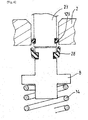
- the pressurized fluid connection 1 shown in [ Fig. 1 ] is comprising a body 2 delimiting an internal circuit 3 for withdrawing (and possibly filling fluid).
- This circuit 3 extends between an upstream end 5 intended to be connected with a pressurized fluid storage volume (storage volume of one or more bottles for example) and a downstream end 6 intended to be connected with a device for withdrawing and / or filling pressurized fluid.
- the connector 1 comprises, at the level of the downstream end 6 of the circuit 3, a dust cover 8 movable relative to the body 2 between a closed position of the downstream end 6 of the circuit 3 and at least one open position (in open position at [ Fig. 1 ]).
- connection 1 comprises an isolation valve 7 arranged in series with the dust protection valve 8 in the internal circuit 3, the isolation valve 7 being arranged upstream of the dust protection valve 8 (the upstream-val direction is reference to the direction of fluid flow in circuit 3 from the upstream end to the downstream end 6.
- each valve 8, 7 is biased by a return member such as a respective spring 14, 10 towards a closed position (towards a respective seat for example).
- the dust cover 8 is in the open position ("O") under the action of a capet pusher pin 23 of a conditioning device or outlet 33.
- the dust cover 8 is a residual pressure valve configured, when it is in the closed position, to maintain a determined minimum pressure. in circuit 3 (tight closing) and allowing gas to be evacuated to the outside in the event of an overpressure in circuit 3 above a pressure threshold determined with respect to the outside (controlled non-tight closing).
- the dust-proof valve 8 comprises a deformable gasket 28 which, in the closed position of the dust-proof valve 8, is in sealed contact against the body 2 when the pressure differential between the circuit 3 and the outside is lower than the determined pressure threshold (cf. [ Fig. 3 ]). In this closed position, the seal 28 may deform / move and allow fluid to be evacuated to the outside in the event of excess pressure in circuit 3 above the threshold (cf. [ Fig. 4 ]).
- This pressure threshold determined with respect to the outside can be between 200mbar and 10bar (or more in particular 15, bar, 20bar or more), in particular between 200mbar and six to eight bar, for example at a value between 1 to 6bar .
- This provides the advantage of maintaining a residual pressure in the connection 1 or valve regardless of the steps of connection to the valve.
- this makes it possible to perform a residual pressure maintenance function that does not present a hissing problem or risk of non-reclosing by the absence of dynamic sealing with a valve opening member.
- this allows a self-regulated residual pressure to be maintained, the maximum value of which does not degrade the ergonomics of the connection (residual pressure multiplied by the bearing surface being less than the necessary connection force).
- One advantage of keeping the residual pressure is that it prevents any risk of ingress of pollution coming from the outside in addition to the protection generated by the seal 28 and the dust-proof valve 8 itself.
- the dust-proof valve 8 may include an annular peripheral seal 28 forming a lip which comes to bear in a sealed manner on the edge of the inlet orifice of the circuit 3. This lip is liable to deform and / or to buckle. move to break the seal with the body 2 of the valve at the inlet.
- the seal 28 comprises a first annular end integral with the dust cover 8 (in a circular groove of the valve) and a second end forming the lip, this second end of the seal 28 being located downstream of the first end of the seal. 28 (cf. for example [ Fig. 3 ]).
- the seal 28 may be separate from the piston but could of course be overmolded and / or vulcanized on the piston.
- the downstream end 6 of the circuit 3 opens out at a downstream end of the connector 1 at the level of a cylindrical bore.
- the dust-proof valve 8 comprising a piston movable in the bore and equipped with a groove accommodating the seal 28. This seal 28 being in sealed contact with the bore when the dust-proof valve 8 is in the closed position (cf. [ Fig. 3 ]).
- the dust-barrier valve 8 is no longer in sealed contact with the bore of the downstream end of the circuit (cf. [ Fig. 6 ]).
- the dust-proof valve 8 is in the closed position (storage position for example) in which it is preferably flush with the end surface of the connector 1.
- the dust-proof valve 8 comprises a peripheral O-ring 28 forming a lip which comes to rest sealingly on the circular edge of the orifice formed in the body 2 of the valve. For example, the lip faces upwards (towards the outlet of tap 2).
- the contact between the gasket 28 of the dust barrier 8 and the bore delimiting its passage opening provides a gas seal which ensures that the upstream chamber of the dust barrier 8 is not vented.
- the seal 28 may deform under the effect of the pressure inside (upstream of the dust barrier 8) so as to expel the excess pressure to the outside.
- the dust-proof valve 8 is in the closed position but ensuring an evacuation of excess gas to the outside of the valve 2 (storage position with pressure evacuation).
- the end of the seal 28 is pushed back by the excess pressure upstream, the seal is broken to allow only the evacuation of the gas.
- the seal 28 returns to its sealed closed position previously described.
- this measured opening is only possible in the direction of discharge and under certain pressure differential conditions between the interior (between the upstream side of the dust barrier 8) and the exterior.
- the seal 28 is sufficiently elastic to return to its initial position after having released the excess pressure, which makes it possible to recover the gas tightness.
- the pressure gradient between the gas contained in the chamber and the outside ensures that the volume of the chamber is not contaminated in the ambient air.
- the dust-proof valve 8 is pushed upstream (towards the inside of the valve 2) by a valve pusher pin 23 which may include a peripheral seal 123 ensuring a seal with the circuit 3 at the level of the 'inlet port.
- the dust-proof valve 8 may still have a seal with the body 2 of the valve.
- the gasket 28 of the dust cover 8 can be positioned on the piston such that the contact between the gasket 28 of the dust cover 8 and the bore n 'is broken only after the sealed contact is established between the seal 123 of the axis 23 and the bore of the body 2.
- the connection of a member 33 carrying the valve pusher 23 on the connector 1 does not reset air the volume of gas in the chamber located upstream of the dust barrier valve 8.
- a module 33 (valve or other) is connected in a sealed manner at the level of the downstream end 6 and this module 33 is equipped with a residual pressure valve (RPV) function, then there is a positive pressure in the connections. even after purging circuit 3 downstream.
- RSV residual pressure valve
- the position of the piston of the dust barrier valve 8, the stroke of the valve pusher 23 present in the valve 2 and the position of the various seals (28 and 123) are preferably such that the seal 28 of the valve 8 protects dust is never in contact with the bore delimiting the orifice or with the valve body. This makes it possible to avoid trapping gas under pressure.
- the gas When gas is withdrawn (from upstream to downstream) the gas can flow downstream from the dust barrier valve 8, for example by means of one or more orifices present in or around the valve pusher 23 or any other suitable part.
- orifices can be provided radially, in particular in the case where the activation of the opening / closing function is done independently.
- a drilling coaxial with the valve pusher axis 23 may be provided for the transit of gas.
- the reverse movement occurs in the direction of closure.
- the seal 28 of the dust shield 8 and the seal 123 of the shaft 23 can be positioned such that the contact between the seal 28 of the dust shield 8 and the bore 2 is established before the sealed contact between the seal 123 of the valve pusher shaft 23 and the bore of the dust cover is not lost. This also makes it possible to avoid contaminating the circuit upstream of the dust-barrier valve 8.
- the residual pressure valve function is therefore present on the first valve 2 thanks to the dust barrier valve 8 as described below. -above.
- the residual pressure valve function can be performed by another residual pressure valve which is housed in the second valve in fluid connection with the circuit of the first valve. This allows to avoid the resonance of an oscillator in the system.
- This dust barrier valve 8 forming a residual pressure valve can be provided on other fittings or taps and in particular on a fitting or tap 1 comprising three valves in series as illustrated by way of example in [ Fig. 2 ].
- the connector 1 may comprise, arranged in series from upstream to downstream in the internal circuit 3 between the upstream end 5 and the downstream end 6: an upstream valve 11, the isolation valve 7 and the valve 8 dust cover.
- the two valves of the embodiment of the [ Fig. 1 ] or the three valves of the embodiment of [ Fig. 2 ] can be chain operated by moving the valve 8 by dust as detailed in the document FR3033386 A1 .
- the dust-barrier valve 8 can be moved from its downstream closed position to a first determined upstream position called “contactless" opening the downstream end of the circuit 3, in which the upstream end 108 of the dust-barrier valve 8 does not push. isolation valve 7 (no contact with isolation valve 7).
- This position can be obtained for example by connecting to the downstream end of the body 2 of the valve 1 a tool 33 for filling and / or drawing off.
- the tool 33 comprises a member 23 pushing the movable valve which slightly moves the valve 8 by dust from downstream to upstream.
- the valve pusher 23 can be moved, for example, via a pivoting lever which can be actuated manually, hydraulically, pneumatically, electrically or by any other suitable actuator.
- this contactless position has many advantages.
- this configuration in which only the dust-proof valve 8 is open makes it possible to connect a filling and / or withdrawal tool in a sealed manner to the downstream end of the valve 2 with a constant force whatever the pressure level in upstream of the isolation valve 7.
- the pressure upstream of the dust-barrier valve 8 may be the same as outside the valve (ambient atmospheric pressure), in particular when the dust-barrier valve 8 closes the downstream end 6 in a non-watertight manner. of circuit 3.
- this contactless configuration also allows a filling / withdrawing tool to perform leak testing of the isolation valve 7.
- the filling / withdrawing tool is connected in a sealed manner to the end 6 of the valve and can be configured to create a vacuum (depression) in the downstream part of the circuit 3 (downstream of the isolation valve 7). This makes it possible to carry out one or more tests to check / qualify the level of tightness of the valve 7 and of the tool, for example before subjecting the mechanism to high pressures.
- the dust-barrier valve 8 can be moved further upstream in a second determined upstream position called "contact" opening the downstream end 6 of the circuit 3 and in which the upstream end 108 of the dust-barrier valve 8 pushes. a downstream end of the isolation valve 7. The isolation valve 7 is then moved by contact out of its seat 9 to a first upstream opening position of the circuit 3 in which the isolation valve 7 does not push the third upstream valve 11.
- the valve 1 can include a calibrated orifice 4 defining a determined opening allowing gas to flow between the upstream and downstream side of the upstream valve 11 when the latter is in its position for closing the circuit 3.
- This determined opening of the calibrated orifice 4 is however less than the opening produced when the upstream valve 11 is in its open position of the circuit 3. In this case, in this position, the pressurized fluid can escape. towards the downstream end according to the flow rate imposed by the calibrated orifice 4.
- the first two valves 8, 7 are opened mechanically while the third upstream valve 11 is in the closed position, but a calibrated flow rate can still escape.
- This configuration corresponds to a start of withdrawal via a progressive opening of the circuit making it possible to control a progressive rise in pressure downstream.
- the dust-barrier valve 8 can be moved even further upstream in a third determined upstream position opening the circuit 3.
- the upstream end 108 of the dust-barrier valve 8 pushes a downstream end of the valve 7 of movable isolation to move by contact the isolation valve 7 out of its seat 9 to a second upstream opening position of the circuit 3.
- the isolation valve 7 pushes the upstream valve 11 into an open position complete from the upstream end of the circuit 3. That is to say that, in this case, the three valves 8, 7, 11 are completely open allowing maximum circulation of fluid.
- This configuration corresponds to a state of filling or drawing off of a reservoir 40 through the tap 1.
- the possible calibrated orifice 4 delimits an opening having a first determined section SI while the opening produced when the upstream valve 11 is in its open position of the circuit 3 has a second determined section S2 so that the ratio between the first section S1 and the second section S2 is between 1/100 and 1/20 and preferably 1/80 and 1/30.
- the passage (first opening section S1) of the calibrated orifice can be obtained by altering the sealing line between the upstream valve 11 and its seat 15 by broaching, a saw cut or other tool on the valve or on his seat.
- the valve 11 may not be perfectly cylindrical (faceted ball, porous ball, or of any other shape to allow the gas to pass with a limited flow rate).
- Another alternative or cumulative solution is to place a calibrated orifice in parallel with this upstream valve 11, to ensure the limited passage of gas.
- this calibrated orifice can pass through the body of the upstream valve 11.
Landscapes
- Engineering & Computer Science (AREA)
- Mechanical Engineering (AREA)
- General Engineering & Computer Science (AREA)
- Filling Or Discharging Of Gas Storage Vessels (AREA)
Claims (13)
- Anschluss für unter Druck stehendes Fluid, insbesondere für einen Druckgasspeicher, wobei der Anschluss (1) dazu bestimmt ist, mit einem Gerät zum Füllen und/oder Entnehmen von unter Druck stehendem Fluid zusammenzuwirken, wobei der Anschluss (1) einen Körper (2) umfasst, der einen inneren Kreis (3) zum Entnehmen und gegebenenfalls Füllen von Fluid begrenzt, wobei sich der Kreis (3) zwischen einem stromaufwärtigen Ende (5), das dazu bestimmt ist, mit einem Speichervolumen für unter Druck stehendes Fluid in Verbindung gebracht zu werden, und einem stromabwärtigen Ende (6), das dazu bestimmt ist, mit einem Gerät zum Entnehmen und/oder Füllen von unter Druck stehendem Fluid verbunden zu werden, erstreckt, wobei der Anschluss (1) auf Höhe des stromabwärtigen Endes (6) des Kreises (3) ein Staubschutzventil (8) umfasst, das relativ zum Körper (2) zwischen einer Verschließstellung des stromabwärtigen Endes (6) des Kreises (3) und mindestens einer Öffnungsstellung beweglich ist, dadurch gekennzeichnet, dass das Staubschutzventil (8) ein Restdruckventil ist, das dazu ausgebildet ist, wenn es in der geschlossenen Stellung ist, einen bestimmten Mindestdruck in dem Kreis (3) zu halten und das ein Abführen von Gas nach außen im Fall eines Überdrucks in dem Kreis (3) oberhalb eines bestimmten Druckschwellenwerts in Bezug auf den Außenraum ermöglicht.
- Anschluss nach Anspruch 1, dadurch gekennzeichnet, dass er eine verformbare Dichtung (28) umfasst, die in geschlossener Stellung des Staubschutzventils (8) auf dem Staubschutzventil (8) gelegen ist, wobei die Dichtung (28) in dichtem Kontakt gegen den Körper (2) ist, wenn in dieser Stellung die Druckdifferenz zwischen dem Kreis (3) und dem Außenraum geringer als der Druckschwellenwert ist, wobei sich die Dichtung (28) im Fall eines Drucküberschusses in dem Kreis (3) oberhalb des Schwellenwerts verformt und ein Abführen von Fluid nach außen zulässt.
- Anschluss nach Anspruch 1 oder 2, dadurch gekennzeichnet, dass das Staubschutzventil (8) dazu ausgestaltet ist, in geschlossener Stellung ein Abführen von Gas zu gewährleisten, indem es das stromabwärtige Ende (6) des Kreises (3) im Fall eines Überdrucks in dem Kreis (3) oberhalb eines bestimmten Druckschwellenwerts in Bezug auf den Außenraum zwischen 200 mbar und 20 bar, insbesondere zwischen 200 mbar und zehn bar, beispielsweise bei einem Wert zwischen 1 bis 6 bar, öffnet.
- Anschluss nach einem der Ansprüche 1 bis 3, dadurch gekennzeichnet, dass das Staubschutzventil (8) eine Umfangsdichtung (28) umfasst, die eine Lippe bildet, die dicht auf dem Rand der Einlassöffnung aufliegt, wobei die Lippe geeignet ist, sich zu verformen und/oder sich zu verlagern, um die Abdichtung mit dem Körper (2) des Hahns auf Höhe des Einlasses zu unterbrechen.
- Anschluss nach Anspruch 4, dadurch gekennzeichnet, dass die Dichtung (28) ein erstes Ende umfasst, das fest mit dem Staubschutzventil (8) verbunden ist, und ein die Lippe bildendes zweites Ende, wobei das zweite Ende der Dichtung (28) stromab des ersten Endes der Dichtung (28) gelegen ist.
- Anschluss nach einem der Ansprüche 1 bis 5, dadurch gekennzeichnet, dass das stromabwärtige Ende (6) des Kreises (3) auf Höhe eines stromabwärtigen Endes des Anschlusses (1) auf Höhe einer zylindrischen Bohrung mündet, wobei das Staubschutzventil (8) einen Kolben beinhaltet, der in der Bohrung beweglich ist und mit einer Nut ausgestattet ist, welche die Dichtung (28) aufnimmt, wobei die Dichtung (28) in dichtem Kontakt mit der Bohrung ist, wenn das Staubschutzventil (8) in der geschlossenen Stellung ist.
- Anschluss nach Anspruch 6, dadurch gekennzeichnet, dass, in einer bestimmten geöffneten Stellung des Staubschutzventils (8), das Staubschutzventil (8) nicht mehr in dichtem Kontakt mit der Bohrung des stromabwärtigen Endes des Kreises (3) ist.
- Anschluss nach einem der Ansprüche 1 bis 7, dadurch gekennzeichnet, dass das Staubschutzventil (8) von einem Rückstellelement (14) zu seiner geschlossenen Stellung hin beansprucht wird.
- Anschluss nach einem der Ansprüche 1 bis 8, dadurch gekennzeichnet, dass er ein Absperrventil (7) umfasst, das in Reihe mit dem Staubschutzventil (8) in dem inneren Kreis (3) angeordnet ist, wobei das Absperrventil (7) stromauf des Staubschutzventils (8) angeordnet ist.
- Anschluss nach Anspruch 9, dadurch gekennzeichnet, dass er, in Reihe von stromauf nach stromab im inneren Kreis (3) zwischen dem stromaufwärtigen Ende (5) und dem stromabwärtigen Ende (6) angeordnet, umfasst: ein stromaufwärtiges Ventil (11), das Absperrventil (7) und das Staubschutzventil (8).
- Hahn für unter Druck stehendes Fluid, der einen Anschluss nach einem der Ansprüche 1 bis 10 umfasst.
- Behälter für unter Druck stehendes Fluid, insbesondere Gasdruckflasche oder Gasdruckflaschenanordnung, umfassend einen Anschluss (1) nach einem der Ansprüche 1 bis 9 oder einen Hahn nach Anspruch 11.
- Verfahren zum Anschließen eines Geräts zum Entnehmen und/oder Füllen an den Kreis (3) eines Anschlusses (1) nach einem der Ansprüche 1 bis 12, wobei das Verfahren einen Füllstutzen verwendet, der auf lösbare Weise mechanisch mit dem Körper (2) des Anschlusses (1) verbunden wird und einen Ventilschieber (23) besitzt, wobei das Verfahren einen Schritt des Verlagerns des Staubschutzventils (8) von stromauf nach stromab aus seiner geschlossenen Stellung hin zu einer geöffneten Stellung durch den Ventilschieber (23) beinhaltet, wobei der Ventilschieber (23) eine Dichtung (123) umfasst, die mit dem stromabwärtigen Ende des Kreises (3) zusammenwirkt, und wobei während eines ersten Teils des Verlagerungshubs des Staubschutzventils (8) hin zu seiner geöffneten Stellung der Ventilschieber (23) und das Staubschutzventil (8) in dichtem Kontakt mit dem stromabwärtigen Ende des Kreises (3) sind, dann, während eines zweiten Teils des Verlagerungsweges des Staubschutzventils (8) hin zu seiner geöffneten Stellung, der Ventilschieber (23) in dichtem Kontakt mit dem stromabwärtigen Ende des Kreises (3) bleibt, während das Staubschutzventil (8) eine geöffnete Stellung erreicht, in der das Staubschutzventil (8) nicht mehr in dichtem Kontakt mit dem stromabwärtigen Ende des Kreises (3) ist.
Applications Claiming Priority (1)
| Application Number | Priority Date | Filing Date | Title |
|---|---|---|---|
| FR1902485A FR3093782B1 (fr) | 2019-03-12 | 2019-03-12 | Raccord de fluide sous pression, robinet et récipient comprenant un tel raccord et procédé de raccordement |
Publications (2)
| Publication Number | Publication Date |
|---|---|
| EP3708900A1 EP3708900A1 (de) | 2020-09-16 |
| EP3708900B1 true EP3708900B1 (de) | 2021-12-15 |
Family
ID=67185400
Family Applications (1)
| Application Number | Title | Priority Date | Filing Date |
|---|---|---|---|
| EP20160881.7A Active EP3708900B1 (de) | 2019-03-12 | 2020-03-04 | Unter druck stehender fluid-anschluss, hahn und behälter, der einen solchen anschluss umfasst, und anschlussverfahren |
Country Status (2)
| Country | Link |
|---|---|
| EP (1) | EP3708900B1 (de) |
| FR (1) | FR3093782B1 (de) |
Families Citing this family (1)
| Publication number | Priority date | Publication date | Assignee | Title |
|---|---|---|---|---|
| FR3155884B1 (fr) * | 2023-11-29 | 2025-11-21 | Lair Liquide Sa Pour L’Etude Et Lexploitation Des Procedes Georges Claude | Dispositif de conditionnement pour un fluide sous pression |
Family Cites Families (6)
| Publication number | Priority date | Publication date | Assignee | Title |
|---|---|---|---|---|
| FR2311989A2 (fr) | 1975-05-23 | 1976-12-17 | Utilisation Ration Gaz | Ensemble d'obturation de securite notamment pour bouteilles de gaz sous pression |
| PT1530002E (pt) * | 2003-11-04 | 2006-09-29 | Cavagna Group Spa | Valvula para recipientes de fluidos pressurizados com dispositivo de bloqueio de sujidade |
| FR2962519B1 (fr) * | 2010-07-09 | 2012-07-20 | Air Liquide | Raccord de remplissage, recipient et procede de remplissage correspondants |
| FR2962521B1 (fr) * | 2010-07-09 | 2012-07-20 | Air Liquide | Raccord de remplissage, recipient et procede de remplissage |
| FR2978432B1 (fr) * | 2011-07-26 | 2014-12-05 | Air Liquide | Raccord de remplissage, recipient, procede de remplissage et prise de conditionnement |
| FR3033386B1 (fr) | 2015-03-04 | 2017-10-27 | Air Liquide | Robinet, recipient et procedes de remplissage, de soutirage et de mise sous vide |
-
2019
- 2019-03-12 FR FR1902485A patent/FR3093782B1/fr not_active Expired - Fee Related
-
2020
- 2020-03-04 EP EP20160881.7A patent/EP3708900B1/de active Active
Also Published As
| Publication number | Publication date |
|---|---|
| EP3708900A1 (de) | 2020-09-16 |
| FR3093782B1 (fr) | 2021-02-12 |
| FR3093782A1 (fr) | 2020-09-18 |
Similar Documents
| Publication | Publication Date | Title |
|---|---|---|
| EP2591273B1 (de) | Befüllungsanschluss, entsprechender behälter und entsprechendes befüllungsverfahren | |
| EP2737234B1 (de) | Füllanschluss, behälter, füllverfahren und fülldüse | |
| EP3265716B1 (de) | Ventil, behälter und verfahren zum füllen, extrahieren und abführen | |
| EP2394080B1 (de) | Vorrichtung zur selektiven blockierung eines durchflusses | |
| EP3708899B1 (de) | Hahn, unter druck stehender fluid-behälter und verfahren zum füllen und entnehmen | |
| FR2861655A1 (fr) | Dispositif d'obturation d'une tubulure de remplissage d'un reservoir a liquide, reservoir equipe d'un tel dispositif et vehicule automobile comprenant un tel reservoir | |
| EP2591274B1 (de) | Füllanschluss, behälter und füllverfahren | |
| EP2010886B1 (de) | Vorrichtung zur entnahme unter druck stehender proben | |
| EP3708900B1 (de) | Unter druck stehender fluid-anschluss, hahn und behälter, der einen solchen anschluss umfasst, und anschlussverfahren | |
| EP4034803B1 (de) | Verpackungsvorrichtung, anordnung mit einer solchen vorrichtung und einem behälter, deren verwendung und verfahren zum füllen oder entnehmen | |
| FR2957626A1 (fr) | Actionneur d'ouverture d'urgence a gaz d'un ouvrant d'aeronef, comportant des moyens d'echappement du gaz | |
| EP0493155B1 (de) | Ventil und Verfahren zur Hydraulikkreislaufentlüftung | |
| EP4463618B1 (de) | Vorrichtung zur montage auf einem ölreservoir einer flugzeugturbomaschine, zugehörige ölversorgungsanordnung und zugehöriges verfahren zur verwendung | |
| FR2955170A1 (fr) | Robinet de gaz et bouteille de gaz sous pression comportant un tel robinet | |
| EP0340111B1 (de) | Differential-Auslöseventil für Leitungen von Flüssigkeiten unter Druck | |
| EP4563875A1 (de) | Verpackungsvorrichtung für ein unter druck stehendes fluid | |
| FR2670859A1 (fr) | Soupape de purge pour circuit hydraulique et procede de purge d'un circuit hydraulique muni d'une telle soupape. |
Legal Events
| Date | Code | Title | Description |
|---|---|---|---|
| PUAI | Public reference made under article 153(3) epc to a published international application that has entered the european phase |
Free format text: ORIGINAL CODE: 0009012 |
|
| STAA | Information on the status of an ep patent application or granted ep patent |
Free format text: STATUS: THE APPLICATION HAS BEEN PUBLISHED |
|
| AK | Designated contracting states |
Kind code of ref document: A1 Designated state(s): AL AT BE BG CH CY CZ DE DK EE ES FI FR GB GR HR HU IE IS IT LI LT LU LV MC MK MT NL NO PL PT RO RS SE SI SK SM TR |
|
| AX | Request for extension of the european patent |
Extension state: BA ME |
|
| STAA | Information on the status of an ep patent application or granted ep patent |
Free format text: STATUS: REQUEST FOR EXAMINATION WAS MADE |
|
| 17P | Request for examination filed |
Effective date: 20210316 |
|
| RBV | Designated contracting states (corrected) |
Designated state(s): AL AT BE BG CH CY CZ DE DK EE ES FI FR GB GR HR HU IE IS IT LI LT LU LV MC MK MT NL NO PL PT RO RS SE SI SK SM TR |
|
| RIC1 | Information provided on ipc code assigned before grant |
Ipc: F17C 13/04 20060101AFI20210701BHEP |
|
| GRAP | Despatch of communication of intention to grant a patent |
Free format text: ORIGINAL CODE: EPIDOSNIGR1 |
|
| STAA | Information on the status of an ep patent application or granted ep patent |
Free format text: STATUS: GRANT OF PATENT IS INTENDED |
|
| INTG | Intention to grant announced |
Effective date: 20210806 |
|
| GRAS | Grant fee paid |
Free format text: ORIGINAL CODE: EPIDOSNIGR3 |
|
| GRAA | (expected) grant |
Free format text: ORIGINAL CODE: 0009210 |
|
| STAA | Information on the status of an ep patent application or granted ep patent |
Free format text: STATUS: THE PATENT HAS BEEN GRANTED |
|
| AK | Designated contracting states |
Kind code of ref document: B1 Designated state(s): AL AT BE BG CH CY CZ DE DK EE ES FI FR GB GR HR HU IE IS IT LI LT LU LV MC MK MT NL NO PL PT RO RS SE SI SK SM TR |
|
| REG | Reference to a national code |
Ref country code: GB Ref legal event code: FG4D Free format text: NOT ENGLISH Ref country code: CH Ref legal event code: EP |
|
| REG | Reference to a national code |
Ref country code: IE Ref legal event code: FG4D Free format text: LANGUAGE OF EP DOCUMENT: FRENCH Ref country code: DE Ref legal event code: R096 Ref document number: 602020001251 Country of ref document: DE |
|
| REG | Reference to a national code |
Ref country code: AT Ref legal event code: REF Ref document number: 1455736 Country of ref document: AT Kind code of ref document: T Effective date: 20220115 |
|
| REG | Reference to a national code |
Ref country code: LT Ref legal event code: MG9D |
|
| REG | Reference to a national code |
Ref country code: NL Ref legal event code: MP Effective date: 20211215 |
|
| PG25 | Lapsed in a contracting state [announced via postgrant information from national office to epo] |
Ref country code: RS Free format text: LAPSE BECAUSE OF FAILURE TO SUBMIT A TRANSLATION OF THE DESCRIPTION OR TO PAY THE FEE WITHIN THE PRESCRIBED TIME-LIMIT Effective date: 20211215 Ref country code: LT Free format text: LAPSE BECAUSE OF FAILURE TO SUBMIT A TRANSLATION OF THE DESCRIPTION OR TO PAY THE FEE WITHIN THE PRESCRIBED TIME-LIMIT Effective date: 20211215 Ref country code: FI Free format text: LAPSE BECAUSE OF FAILURE TO SUBMIT A TRANSLATION OF THE DESCRIPTION OR TO PAY THE FEE WITHIN THE PRESCRIBED TIME-LIMIT Effective date: 20211215 Ref country code: BG Free format text: LAPSE BECAUSE OF FAILURE TO SUBMIT A TRANSLATION OF THE DESCRIPTION OR TO PAY THE FEE WITHIN THE PRESCRIBED TIME-LIMIT Effective date: 20220315 |
|
| REG | Reference to a national code |
Ref country code: AT Ref legal event code: MK05 Ref document number: 1455736 Country of ref document: AT Kind code of ref document: T Effective date: 20211215 |
|
| PG25 | Lapsed in a contracting state [announced via postgrant information from national office to epo] |
Ref country code: SE Free format text: LAPSE BECAUSE OF FAILURE TO SUBMIT A TRANSLATION OF THE DESCRIPTION OR TO PAY THE FEE WITHIN THE PRESCRIBED TIME-LIMIT Effective date: 20211215 Ref country code: NO Free format text: LAPSE BECAUSE OF FAILURE TO SUBMIT A TRANSLATION OF THE DESCRIPTION OR TO PAY THE FEE WITHIN THE PRESCRIBED TIME-LIMIT Effective date: 20220315 Ref country code: LV Free format text: LAPSE BECAUSE OF FAILURE TO SUBMIT A TRANSLATION OF THE DESCRIPTION OR TO PAY THE FEE WITHIN THE PRESCRIBED TIME-LIMIT Effective date: 20211215 Ref country code: HR Free format text: LAPSE BECAUSE OF FAILURE TO SUBMIT A TRANSLATION OF THE DESCRIPTION OR TO PAY THE FEE WITHIN THE PRESCRIBED TIME-LIMIT Effective date: 20211215 Ref country code: GR Free format text: LAPSE BECAUSE OF FAILURE TO SUBMIT A TRANSLATION OF THE DESCRIPTION OR TO PAY THE FEE WITHIN THE PRESCRIBED TIME-LIMIT Effective date: 20220316 |
|
| PG25 | Lapsed in a contracting state [announced via postgrant information from national office to epo] |
Ref country code: NL Free format text: LAPSE BECAUSE OF FAILURE TO SUBMIT A TRANSLATION OF THE DESCRIPTION OR TO PAY THE FEE WITHIN THE PRESCRIBED TIME-LIMIT Effective date: 20211215 |
|
| PG25 | Lapsed in a contracting state [announced via postgrant information from national office to epo] |
Ref country code: SM Free format text: LAPSE BECAUSE OF FAILURE TO SUBMIT A TRANSLATION OF THE DESCRIPTION OR TO PAY THE FEE WITHIN THE PRESCRIBED TIME-LIMIT Effective date: 20211215 Ref country code: SK Free format text: LAPSE BECAUSE OF FAILURE TO SUBMIT A TRANSLATION OF THE DESCRIPTION OR TO PAY THE FEE WITHIN THE PRESCRIBED TIME-LIMIT Effective date: 20211215 Ref country code: RO Free format text: LAPSE BECAUSE OF FAILURE TO SUBMIT A TRANSLATION OF THE DESCRIPTION OR TO PAY THE FEE WITHIN THE PRESCRIBED TIME-LIMIT Effective date: 20211215 Ref country code: PT Free format text: LAPSE BECAUSE OF FAILURE TO SUBMIT A TRANSLATION OF THE DESCRIPTION OR TO PAY THE FEE WITHIN THE PRESCRIBED TIME-LIMIT Effective date: 20220418 Ref country code: ES Free format text: LAPSE BECAUSE OF FAILURE TO SUBMIT A TRANSLATION OF THE DESCRIPTION OR TO PAY THE FEE WITHIN THE PRESCRIBED TIME-LIMIT Effective date: 20211215 Ref country code: EE Free format text: LAPSE BECAUSE OF FAILURE TO SUBMIT A TRANSLATION OF THE DESCRIPTION OR TO PAY THE FEE WITHIN THE PRESCRIBED TIME-LIMIT Effective date: 20211215 Ref country code: CZ Free format text: LAPSE BECAUSE OF FAILURE TO SUBMIT A TRANSLATION OF THE DESCRIPTION OR TO PAY THE FEE WITHIN THE PRESCRIBED TIME-LIMIT Effective date: 20211215 |
|
| PG25 | Lapsed in a contracting state [announced via postgrant information from national office to epo] |
Ref country code: PL Free format text: LAPSE BECAUSE OF FAILURE TO SUBMIT A TRANSLATION OF THE DESCRIPTION OR TO PAY THE FEE WITHIN THE PRESCRIBED TIME-LIMIT Effective date: 20211215 Ref country code: AT Free format text: LAPSE BECAUSE OF FAILURE TO SUBMIT A TRANSLATION OF THE DESCRIPTION OR TO PAY THE FEE WITHIN THE PRESCRIBED TIME-LIMIT Effective date: 20211215 |
|
| REG | Reference to a national code |
Ref country code: DE Ref legal event code: R097 Ref document number: 602020001251 Country of ref document: DE |
|
| PG25 | Lapsed in a contracting state [announced via postgrant information from national office to epo] |
Ref country code: IS Free format text: LAPSE BECAUSE OF FAILURE TO SUBMIT A TRANSLATION OF THE DESCRIPTION OR TO PAY THE FEE WITHIN THE PRESCRIBED TIME-LIMIT Effective date: 20220415 |
|
| PLBE | No opposition filed within time limit |
Free format text: ORIGINAL CODE: 0009261 |
|
| STAA | Information on the status of an ep patent application or granted ep patent |
Free format text: STATUS: NO OPPOSITION FILED WITHIN TIME LIMIT |
|
| PG25 | Lapsed in a contracting state [announced via postgrant information from national office to epo] |
Ref country code: MC Free format text: LAPSE BECAUSE OF FAILURE TO SUBMIT A TRANSLATION OF THE DESCRIPTION OR TO PAY THE FEE WITHIN THE PRESCRIBED TIME-LIMIT Effective date: 20211215 Ref country code: DK Free format text: LAPSE BECAUSE OF FAILURE TO SUBMIT A TRANSLATION OF THE DESCRIPTION OR TO PAY THE FEE WITHIN THE PRESCRIBED TIME-LIMIT Effective date: 20211215 Ref country code: AL Free format text: LAPSE BECAUSE OF FAILURE TO SUBMIT A TRANSLATION OF THE DESCRIPTION OR TO PAY THE FEE WITHIN THE PRESCRIBED TIME-LIMIT Effective date: 20211215 |
|
| 26N | No opposition filed |
Effective date: 20220916 |
|
| PG25 | Lapsed in a contracting state [announced via postgrant information from national office to epo] |
Ref country code: SI Free format text: LAPSE BECAUSE OF FAILURE TO SUBMIT A TRANSLATION OF THE DESCRIPTION OR TO PAY THE FEE WITHIN THE PRESCRIBED TIME-LIMIT Effective date: 20211215 |
|
| REG | Reference to a national code |
Ref country code: BE Ref legal event code: MM Effective date: 20220331 |
|
| PG25 | Lapsed in a contracting state [announced via postgrant information from national office to epo] |
Ref country code: LU Free format text: LAPSE BECAUSE OF NON-PAYMENT OF DUE FEES Effective date: 20220304 Ref country code: IE Free format text: LAPSE BECAUSE OF NON-PAYMENT OF DUE FEES Effective date: 20220304 |
|
| PG25 | Lapsed in a contracting state [announced via postgrant information from national office to epo] |
Ref country code: BE Free format text: LAPSE BECAUSE OF NON-PAYMENT OF DUE FEES Effective date: 20220331 |
|
| PG25 | Lapsed in a contracting state [announced via postgrant information from national office to epo] |
Ref country code: IT Free format text: LAPSE BECAUSE OF FAILURE TO SUBMIT A TRANSLATION OF THE DESCRIPTION OR TO PAY THE FEE WITHIN THE PRESCRIBED TIME-LIMIT Effective date: 20211215 |
|
| REG | Reference to a national code |
Ref country code: CH Ref legal event code: PL |
|
| PG25 | Lapsed in a contracting state [announced via postgrant information from national office to epo] |
Ref country code: LI Free format text: LAPSE BECAUSE OF NON-PAYMENT OF DUE FEES Effective date: 20230331 Ref country code: CH Free format text: LAPSE BECAUSE OF NON-PAYMENT OF DUE FEES Effective date: 20230331 |
|
| PG25 | Lapsed in a contracting state [announced via postgrant information from national office to epo] |
Ref country code: MK Free format text: LAPSE BECAUSE OF FAILURE TO SUBMIT A TRANSLATION OF THE DESCRIPTION OR TO PAY THE FEE WITHIN THE PRESCRIBED TIME-LIMIT Effective date: 20211215 Ref country code: CY Free format text: LAPSE BECAUSE OF FAILURE TO SUBMIT A TRANSLATION OF THE DESCRIPTION OR TO PAY THE FEE WITHIN THE PRESCRIBED TIME-LIMIT Effective date: 20211215 |
|
| PG25 | Lapsed in a contracting state [announced via postgrant information from national office to epo] |
Ref country code: HU Free format text: LAPSE BECAUSE OF FAILURE TO SUBMIT A TRANSLATION OF THE DESCRIPTION OR TO PAY THE FEE WITHIN THE PRESCRIBED TIME-LIMIT; INVALID AB INITIO Effective date: 20200304 |
|
| PG25 | Lapsed in a contracting state [announced via postgrant information from national office to epo] |
Ref country code: TR Free format text: LAPSE BECAUSE OF FAILURE TO SUBMIT A TRANSLATION OF THE DESCRIPTION OR TO PAY THE FEE WITHIN THE PRESCRIBED TIME-LIMIT Effective date: 20211215 |
|
| PG25 | Lapsed in a contracting state [announced via postgrant information from national office to epo] |
Ref country code: MT Free format text: LAPSE BECAUSE OF FAILURE TO SUBMIT A TRANSLATION OF THE DESCRIPTION OR TO PAY THE FEE WITHIN THE PRESCRIBED TIME-LIMIT Effective date: 20211215 |
|
| PGFP | Annual fee paid to national office [announced via postgrant information from national office to epo] |
Ref country code: GB Payment date: 20260324 Year of fee payment: 7 |
|
| PGFP | Annual fee paid to national office [announced via postgrant information from national office to epo] |
Ref country code: DE Payment date: 20260319 Year of fee payment: 7 |
|
| PGFP | Annual fee paid to national office [announced via postgrant information from national office to epo] |
Ref country code: FR Payment date: 20260320 Year of fee payment: 7 |