EP3712604B1 - Système et procédé de mesure de contenu d'électrolyte dans un capteur de gaz électrochimique - Google Patents
Système et procédé de mesure de contenu d'électrolyte dans un capteur de gaz électrochimique Download PDFInfo
- Publication number
- EP3712604B1 EP3712604B1 EP19163539.0A EP19163539A EP3712604B1 EP 3712604 B1 EP3712604 B1 EP 3712604B1 EP 19163539 A EP19163539 A EP 19163539A EP 3712604 B1 EP3712604 B1 EP 3712604B1
- Authority
- EP
- European Patent Office
- Prior art keywords
- electrode
- electrochemical gas
- gas sensor
- wick
- separator material
- Prior art date
- Legal status (The legal status is an assumption and is not a legal conclusion. Google has not performed a legal analysis and makes no representation as to the accuracy of the status listed.)
- Active
Links
Images


Classifications
-
- G—PHYSICS
- G01—MEASURING; TESTING
- G01N—INVESTIGATING OR ANALYSING MATERIALS BY DETERMINING THEIR CHEMICAL OR PHYSICAL PROPERTIES
- G01N27/00—Investigating or analysing materials by the use of electric, electrochemical, or magnetic means
- G01N27/26—Investigating or analysing materials by the use of electric, electrochemical, or magnetic means by investigating electrochemical variables; by using electrolysis or electrophoresis
- G01N27/416—Systems
- G01N27/4163—Systems checking the operation of, or calibrating, the measuring apparatus
-
- G—PHYSICS
- G01—MEASURING; TESTING
- G01N—INVESTIGATING OR ANALYSING MATERIALS BY DETERMINING THEIR CHEMICAL OR PHYSICAL PROPERTIES
- G01N27/00—Investigating or analysing materials by the use of electric, electrochemical, or magnetic means
- G01N27/02—Investigating or analysing materials by the use of electric, electrochemical, or magnetic means by investigating impedance
- G01N27/04—Investigating or analysing materials by the use of electric, electrochemical, or magnetic means by investigating impedance by investigating resistance
-
- G—PHYSICS
- G01—MEASURING; TESTING
- G01N—INVESTIGATING OR ANALYSING MATERIALS BY DETERMINING THEIR CHEMICAL OR PHYSICAL PROPERTIES
- G01N27/00—Investigating or analysing materials by the use of electric, electrochemical, or magnetic means
- G01N27/26—Investigating or analysing materials by the use of electric, electrochemical, or magnetic means by investigating electrochemical variables; by using electrolysis or electrophoresis
- G01N27/403—Cells and electrode assemblies
- G01N27/404—Cells with anode, cathode and cell electrolyte on the same side of a permeable membrane which separates them from the sample fluid, e.g. Clark-type oxygen sensors
-
- G—PHYSICS
- G01—MEASURING; TESTING
- G01N—INVESTIGATING OR ANALYSING MATERIALS BY DETERMINING THEIR CHEMICAL OR PHYSICAL PROPERTIES
- G01N27/00—Investigating or analysing materials by the use of electric, electrochemical, or magnetic means
- G01N27/26—Investigating or analysing materials by the use of electric, electrochemical, or magnetic means by investigating electrochemical variables; by using electrolysis or electrophoresis
- G01N27/403—Cells and electrode assemblies
- G01N27/413—Concentration cells using liquid electrolytes measuring currents or voltages in voltaic cells
Definitions
- Example embodiments of the present disclosure relate generally to a system for measuring electrolyte content in an electrochemical gas sensor and a method for manufacturing an apparatus for measuring electrolyte content in an electrochemical gas sensor.
- electrolyte-based electrochemical gas sensors may use electrolyte-based electrochemical gas sensors to detect the presence of various gasses.
- conventional electrolyte-based electrochemical gas sensor designs are prone to decreased measurement sensitivity and even failure due to evaporation of the electrolyte contained therein.
- EP 2581734 A2 discloses a gas sensor that includes known types of electrodes such as sensing electrodes, counter electrodes or reference electrodes to sense the presence of a predetermined gas.
- at least one diagnostic electrode is carried in the sensor.
- the diagnostic electrode implements at least one diagnostic function without substantially impairing the gas sensing function.
- the diagnostic electrode is immersed in sensor electrolyte.
- WO 2018/059719 A1 discloses a method comprising scanning a diagnostic micro - electrode of an electrochemical sensor using scanning voltammetry at a plurality of electrolyte concentrations; generating a variable set of readings from the first scanning voltammetry scan using a potential difference between a strong hydrogen adsorption peak and an oxide reduction peak and/or oxide formation peak at each of the plurality of electrolyte concentrations; and determining a correlation by plotting the variable set of readings and the plurality of electrolyte concentrations.
- GB 2436144 A discloses an electrochemical gas sensor for sensing two different toxic gases and having a housing with at least one gas inlet to allow gas to diffuse onto a electrode assembly comprising two sensing electrodes formed on a common support with a gap between the two electrodes, the gas passing through a filter housing divided into separate compartments for gas diffusion through each compartment to a respective selected electrode, one compartment allowing the passage of unfiltered gas and the other compartment containing a gas filter to permit passage of a selected gas onto the respective electrode, the filter housing also sealing against the support in the gap between the two electrodes.
- WO 01/31326 A1 discloses an electrochemical gas sensor assembly comprising an electrochemical gas sensor including sensing and counter electrodes , an intervening body of electrolyte contacting the electrodes, a diffusion control for controlling the diffusion of gas to the sensing electrode wherein a gas to be sensed is reacted at the sensing electrode, the electrode being connected in an electrical circuit, the circuit including a monitor for monitoring current flow in the circuit related to the concentration of the gas being sensed.
- the assembly further comprises an electrical biasing system operable in a test mode to bias the sensing electrode relative to the counter electrode to a potential at which oxygen is reduced at the sensing electrode and evolved at the counter electrode, the monitor providing an output indicating the operating condition of the sensor.
- an impedance in an electrochemical gas sensor can be measured by connecting at least one pin in an integrated circuit to at least one electrode in an electrochemical gas sensor, using a damping capacitor to connect the at least one pin in the integrated circuit to an electrical ground, applying a voltage to the electrochemical gas sensor to provide a bias voltage to at least one electrode in the electrochemical gas sensor, receiving a current from at least one electrode in the electrochemical gas sensor, determining a measured gas amount from the received current, activating a switch located within the integrated circuit to isolate the damping capacitor from the at least one pin in the integrated circuit, and measuring an impedance of the electrochemical gas sensor using an excitation signal while the at least one damping capacitor is isolated from the at least one electrode in the electrochemical gas sensor.
- Applicant has identified a number of deficiencies and problems associated with conventional electrolyte-based gas sensors. Through applied effort, ingenuity, and innovation, many of these identified problems have been solved by developing solutions that are included in embodiments of the present disclosure, many examples of which are described in detail herein.
- the disclosure solves these problems by describing a unique design for an electrochemical gas sensor that makes use of a differential wicking approach to sensor design.
- the electrochemical gas sensor disclosed herein comprises two types of fibrous material: one or more separators (e.g., made of separator material such as grade GF/A glass fiber having a mean particle filtration size of about 1.6 ⁇ m), which may be used separate the electrodes; and a wick (e.g., made of a wick material such as BS2000 glass fiber having a mean particle filtration size of about 4.8 ⁇ m), used to fill or partially fill a reservoir and to feed electrolyte to the separators.
- separators e.g., made of separator material such as grade GF/A glass fiber having a mean particle filtration size of about 1.6 ⁇ m
- a wick e.g., made of a wick material such as BS2000 glass fiber having a mean particle filtration size of about 4.8 ⁇ m
- the wick material is designed to be less hydrophilic than the one or more separators so that when the wick material is in contact with the separator material and the electrolyte volume decreases (e.g., due to evaporation), the wick material dries out before the separator material.
- the electrochemical gas sensor disclosed herein is configured to perform a conductivity measurement (e.g., Reflex or Capa type pulse test; single or multiple frequency impedance spectroscopy) across the wick material rather than the typical conductivity measurement across the one or more separators.
- This conductivity measurement will allow the electrochemical gas sensor to monitor the drying of the wick material and provide advance warning of impending failure, since the wick material will dry out before the one or more separators.
- the conductivity measurement is more than a simple "wet vs. dry" measurement since there may be some variation in conductivity as the wick becomes relatively dry and percolation effects result in an increasing impedance.
- the electrochemical gas sensor disclosed herein comprises one or more auxiliary electrodes to measure the conductivity through the wick material.
- the disclosure describes the features of the auxiliary electrode with reference to an electrochemical gas sensor, the auxiliary electrode disclosed herein may be applied in any suitable detector, sensor, gauge, instrument, or application where measurement of electrolyte content is desired.
- Methods of measuring and compensating for electrolyte changes are critical to the development of environmental compensation algorithms, fault diagnostics, and advance failure warnings for electrolyte-based electrochemical gas sensors.
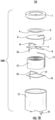
- FIGS. 1A , 1B , 1C , and 1D illustrate exploded views of example electrochemical gas sensors configured to measure electrolyte content.
- FIG. 1A illustrates an exploded view 110 of an example electrochemical gas sensor 100A
- FIG. 1B illustrates an exploded view 120 of an example electrochemical gas sensor 100B
- FIG. 1C illustrates an exploded view 130 of an example electrochemical gas sensor 100C
- FIG. 1A illustrates an exploded view 110 of an example electrochemical gas sensor 100A
- FIG. 1B illustrates an exploded view 120 of an example electrochemical gas sensor 100B
- FIG. 1C illustrates an exploded view 130 of an example electrochemical gas sensor 100C
- electrochemical gas sensor 100 may comprise any combination of components, structures, and features discussed with reference to example electrochemical gas sensor 100A, example electrochemical gas sensor 100B, example electrochemical gas sensor 100C, or example electrochemical gas sensor 100D, including the addition or omission of components, structures, and features.
- the electrochemical gas sensor 100 may be a hardware device with embedded software configured to measure, detect, and transmit data (e.g., temperature, pressure, motion, and other suitable data).
- the embedded software may be configured to run in an apparatus, device, or unit (e.g., firmware).
- the electrochemical gas sensor 100 may be a carbon monoxide sensor.
- the electrochemical gas sensor 100 may be applicable to other sensor and gas types.
- the electrochemical gas sensor 100 may comprise a top cap part 1 having an aperture defining a capillary hole in the center of the top cap part 1 to allow gas access to the sensing electrode 4.
- the electrochemical gas sensor 100 may comprise a filter material 2.
- the filter material 2 may be optionally provided depending on sensor type of the example electrochemical gas sensor 100.
- FIGS. 1A , 1C , and 1D show an example electrochemical gas sensor 100A, an example electrochemical gas sensor 100C, and an example electrochemical gas sensor 100D that includes the filter material 2.
- FIG. 1B shows an example electrochemical gas sensor 100B that does not include the filter material 2.
- the electrochemical gas sensor 100 may comprise a porous polytetrafluoroethylene (PTFE) film tape 3 to support the sensing electrode 4.
- PTFE polytetrafluoroethylene
- the porous PTFE film tape 3 may be sealed against the top cap part 1 to retain electrolyte within the electrochemical gas sensor 100 while allowing gas to diffuse from the capillary hole in the center of the top cap part 1 to the sensing electrode 4 or, in some instances, through the filter material 2 to the sensing electrode 4.
- the electrochemical gas sensor 100 comprises a sensing electrode 4 which may be deposited on porous PTFE film tape 3.
- the sensing electrode 4 may be deposited on the bottom surface of the porous PTFE film tape 3 (e.g., facing downwards) and thus is not visible in in FIGS. 1A , 1B , 1C , and 1D .
- the electrochemical gas sensor 100 may comprise a connecting wire 5 to electrically connect the sensing electrode 4 to a first pin of the pins 16.
- the electrochemical gas sensor 100 comprises a separator material 6.
- the separator material is made of a hydrophilic material, such as a glass fiber material (e.g., grade GF/A glass fiber having a mean particle filtration size of about 1.6 ⁇ m).
- the electrochemical gas sensor 100 comprises a reference electrode 7 deposited onto the top surface of a porous PTFE film tape 9 (e.g., facing upwards).
- the electrochemical gas sensor 100 may comprise a connecting wire 8 to electrically connect the reference electrode 7 to a second pin of the pins 16.
- the electrochemical gas sensor 100 comprises a porous PTFE film tape 9 to support and electrically separate the reference electrode 7 and the counter electrode 10.
- the electrochemical gas sensor 100 comprises a counter electrode 10 deposited onto a bottom surface of the porous PTFE film tape 9 (e.g., facing downwards).
- the electrochemical gas sensor 100 may comprise a connecting wire 11 to electrically connect the counter electrode 10 to a third pin of the pins 16.
- the electrochemical gas sensor 100 may comprise a separator material 12.
- the separator material 12 may be made of a hydrophilic material, such as a glass fiber material (e.g., grade GF/A glass fiber having a mean particle filtration size of about 1.6 ⁇ m).
- the separator material 12 may be optionally provided to maintain wetting of the counter electrode 10 as the wick material 13 dries out (e.g., as the volume of the electrolyte content in the wick material 13 decreases).
- FIGS. 1A , 1C , and 1D show an example electrochemical gas sensor 100A, an example electrochemical gas sensor 100C, and an example electrochemical gas sensor 100D that includes the separator material 12.
- FIG. 1B shows an example electrochemical gas sensor 100B that does not include the separator material 12.
- the electrochemical gas sensor 100 comprises a wick material 13.
- the wick material 13 is made of a hydrophilic material (e.g., BS2000 glass fiber having a mean particle filtration size of about 4.8 ⁇ m).
- the wick material 13 is less hydrophilic than the separator material 6, the separator material 12, or both in order to absorb excess electrolyte material but selectively give up electrolyte material to the separator material 6, the separator material 12, or both as the electrolyte material in the wick material 13 dries out.
- the electrochemical gas sensor 100 may comprise an epoxy material 14.
- the epoxy material 14 may be made of an epoxy material, such as a two-part epoxy amino resin.
- the epoxy material 14 may be optionally provided to protect the inner surface of the pins 16 (e.g., the portion of the pins 16 disposed within the cavity structure of the housing part 15) from contact with electrolyte material.
- FIGS. 1A , 1C , and 1D show an example electrochemical gas sensor 100A, an example electrochemical gas sensor 100C, and an example electrochemical gas sensor 100D that includes the epoxy material 14.
- FIG. 1B shows an example electrochemical gas sensor 100B that does not include the epoxy material 14.
- the electrochemical gas sensor 100 comprises a housing part 15 which may be sealed against the top cap part 1.
- the filter material 2, the porous PTFE film tape 3, the sensing electrode 4, the connecting wire 5, the separator material 6, the reference electrode 7, the connecting wire 8, the porous PTFE film tape 9, the counter electrode 10, the connecting wire 11, the separator material 12, the wick material 13, the epoxy material 14, the inner surface of the pins 16, the auxiliary electrode 17, the connecting wire 18, the film tape 19, the auxiliary electrode 20, the connecting wire 21, the porous PTFE film tape 22, the additional separator disposed between the connecting wire 18 and the wick material 13, or a combination thereof are configured to be disposed in the cavity structure of the housing part 15 and, in some instances, sealed in the cavity structure of the housing part 15 by the top cap part 1.
- the electrochemical gas sensor 100 may comprise a plurality of pins 16 protruding through housing part 15 to provide electrical connection from sensing electrode 4, reference electrode 7, counter electrode 10, auxiliary electrode 17 (or connecting wire 18), auxiliary electrode 20 (or connecting wire 21), or a combination thereof to external circuitry, such as the electrolyte content monitoring circuitry 214 shown in FIG. 2 .
- the electrochemical gas sensor 100 comprises an electrolyte material, such as a liquid electrolyte.
- the electrolyte material is disposed in the wick material 13, the separator material 6, the separator material 12, the additional separator disposed between the connecting wire 18 and the wick material 13, the cavity structure of the housing part 15, or a combination.
- the electrolyte material is a liquid electrolyte disposed at least in the wick material 13 and the separator material 6.
- the electrochemical gas sensor 100 comprises an auxiliary electrode 17 to provide for an impedance measurement across the wick material 13.
- the electrochemical gas sensor 100 may comprise a connecting wire 18 to electrically connect the auxiliary electrode 17 to a fourth pin of the pins 16.
- the electrochemical gas sensor 100 may comprise a film tape 19.
- the auxiliary electrode 17 may be deposited on a top surface of the film tape 19 (e.g., facing upwards).
- the film tape 19 may be a porous PTFE film tape.
- the film tape 19 may be a non-porous tape.
- the film tape 19 may be optionally provided to support the auxiliary electrode 17. For example, FIGS.
- FIG. 1A , 1B , and 1D show an example electrochemical gas sensor 100A, an example electrochemical gas sensor 100B, and an example electrochemical gas sensor 100D that includes the auxiliary electrode 17 deposited on the top surface of the film tape 19.
- FIG. 1C shows an example electrochemical gas sensor 100C that does not include the auxiliary electrode 17 or the film tape 19. Rather, in FIG. 1C , the example electrochemical gas sensor 100C uses the connecting wire 18 itself as the auxiliary electrode.
- the electrochemical gas sensor 100 may comprise an additional separator disposed between the connecting wire 18 and the wick material 13.
- the example electrochemical gas sensor 100 may comprise an additional auxiliary electrode 20 to provide for an impedance measurement across the wick material 13.
- the electrochemical gas sensor 100 may comprise a connecting wire 21 to electrically connect the additional auxiliary electrode 20 to a fifth pin of the pins 16.
- the electrochemical gas sensor 100 may comprise a porous PTFE film tape 22.
- the additional auxiliary electrode 20 may be deposited on a bottom surface of the porous PTFE film tape 22 (e.g., facing downwards).
- the porous PTFE film tape 22 may be optionally provided to support the additional auxiliary electrode 20.
- FIG. 1D shows an example electrochemical gas sensor 100D that includes the additional auxiliary electrode 20 deposited on the bottom surface of the porous PTFE film tape 22.
- the electrochemical gas sensor 100 may not include the additional auxiliary electrode 20 or the porous PTFE film tape 22. Rather, such an example electrochemical gas sensor 100 may use the connecting wire 21 itself as an auxiliary electrode.
- the electrochemical gas sensor (e.g., electrochemical gas sensor 100) comprises a separator material (e.g., separator material 6) comprising a first separator material surface (e.g., the top surface of the separator material 6) and a second separator material surface (e.g., the bottom surface of the separator material 6) opposite the first separator material surface.
- a separator material e.g., separator material 6
- first separator material surface e.g., the top surface of the separator material 6
- second separator material surface e.g., the bottom surface of the separator material
- the electrochemical gas sensor comprises a first electrode (e.g., sensing electrode 4) disposed on the first separator material surface of the separator material (e.g., the top surface of the separator material 6).
- the first electrode may be a sensing electrode (e.g., sensing electrode 4).
- the electrochemical gas sensor (e.g., electrochemical gas sensor 100) may comprise a first connecting wire (e.g., connecting wire 5) configured to connect the first electrode to a first electrical contact (e.g., a first pin of pins 16).
- the electrochemical gas sensor comprises a second electrode (e.g., reference electrode 7) disposed on the second separator material surface of the separator material (e.g., the top surface of the separator material 6).
- the second electrode may be a reference electrode (e.g., reference electrode 7).
- the electrochemical gas sensor (e.g., electrochemical gas sensor 100) may comprise a second connecting wire (e.g., connecting wire 8) configured to connect the second electrode to a second electrical contact (e.g., a second pin of pins 16).
- the electrochemical gas sensor comprises a wick material (e.g., wick material 13) comprising a first wick material surface (e.g., the top surface of the wick material 13) and a second wick material surface (e.g., the bottom surface of the wick material 13) opposite the first wick material surface.
- the wick material is designed to be less hydrophilic than the one or more separators so that when the wick material and the one or more separators are in contact and the electrolyte volume decreases (e.g., due to evaporation), the wick material dries out before the one or more separators.
- the separator material (e.g., separator material 6) comprises a first hydrophilic material (e.g., a material such as grade GF/A glass fiber having a mean particle filtration size of about 1.6 ⁇ m), the wick material comprises a second hydrophilic material (e.g., made of material such as BS2000 glass fiber having a mean particle filtration size of about 4.8 ⁇ m), and the first hydrophilic material is more hydrophilic than the second hydrophilic material.
- a first hydrophilic material e.g., a material such as grade GF/A glass fiber having a mean particle filtration size of about 1.6 ⁇ m
- the wick material comprises a second hydrophilic material (e.g., made of material such as BS2000 glass fiber having a mean particle filtration size of about 4.8 ⁇ m)
- the first hydrophilic material is more hydrophilic than the second hydrophilic material.
- the electrochemical gas sensor comprises a third electrode (e.g., counter electrode 10) disposed facing the first wick material surface of the wick material (e.g., the top surface of the wick material 13).
- the third electrode may be a counter electrode (e.g., counter electrode 10).
- the electrochemical gas sensor (e.g., electrochemical gas sensor 100) may comprise a third connecting wire (e.g., connecting wire 11) configured to connect the third electrode to a third electrical contact (e.g., a third pin of pins 16).
- the third electrode (e.g., counter electrode 10) is disposed on the first wick material surface of the wick material (e.g., the top surface of the wick material 13).
- the separator material (e.g., the separator material 6) may be a first separator material
- the electrochemical gas sensor 100 may comprise a second separator material (e.g., the separator material 12) comprising a third separator material surface (e.g., the top surface of the separator material 12) and a fourth separator material surface (e.g., the bottom surface of the separator material 12) opposite the third separator material surface.
- the third electrode e.g., counter electrode 10) may be configured to be disposed on the third separator material surface of the second separator material (e.g., the top surface of the separator material 12).
- the third separator material surface of the second separator material (e.g., the top surface of the separator material 12) may be configured to be disposed on the third electrode(e.g., counter electrode 10), and the fourth separator material surface of the second separator material (e.g., the bottom surface of the separator material 12) may be configured to be disposed on the first wick material surface of the wick material (e.g., the top surface of the wick material 13).
- the electrochemical gas sensor comprises a fourth electrode (e.g., auxiliary electrode 17, connecting wire 18) disposed on the second wick material surface of the wick material (e.g., the bottom surface of the wick material 13).
- the fourth electrode is configured to measure an electrical conductivity through the wick material.
- the fourth electrode may be an auxiliary electrode (e.g., auxiliary electrode 17).
- the fourth electrode may be a wire electrode (e.g., connecting wire 18).
- the fourth electrode may be an area electrode (e.g., auxiliary electrode 17).
- the fourth electrode may comprise platinum.
- the fourth electrode may comprise carbon.
- the fourth electrode may be porous.
- the fourth electrode may be non-porous.
- the fourth electrode may be disposed on a surface of a PTFE film tape (e.g., the top surface of the film tape 19 wherein the film tape 19 is a PTFE film tape).
- the electrochemical gas sensor e.g., electrochemical gas sensor 100
- the electrochemical gas sensor may comprise a fourth connecting wire (e.g., connecting wire 18) configured to connect the fourth electrode to a fourth electrical contact (e.g., a fourth pin of pins 16).
- the electrochemical gas sensor comprises a housing part (e.g., housing part 15) comprising a cavity structure.
- the separator material e.g., separator material 6
- the first electrode e.g., sensing electrode 4
- the second electrode e.g., reference electrode 7
- the wick material e.g., wick material 13
- the third electrode e.g., counter electrode 10
- the fourth electrode e.g., auxiliary electrode 17, connecting wire 18
- the electrochemical gas sensor may comprise, or be electrically connected to (e.g., via pins 16), electrolyte content monitoring circuitry (e.g., electrolyte content monitoring circuitry 214 shown in FIG. 2 ) in communication with the third electrode (e.g., counter electrode 10) and the fourth electrode (e.g., auxiliary electrode 17, connecting wire 18), wherein the electrolyte content monitoring circuitry is configured to: measure an impedance between the fourth electrode (e.g., auxiliary electrode 17, connecting wire 18) and the third electrode (e.g., counter electrode 10); and measure an electrical conductivity through the wick material (e.g., wick material 13) based on the measured impedance.
- electrolyte content monitoring circuitry e.g., electrolyte content monitoring circuitry 214 shown in FIG. 2
- the third electrode e.g., counter electrode 10
- the fourth electrode e.g., auxiliary electrode 17, connecting wire 18
- the third electrode e.g., counter electrode 10
- the electrochemical gas sensor may comprise a top cap part (e.g., top cap part 1) configured to be disposed on a surface of the housing part (e.g., housing part 15).
- the top cap part may define an aperture configured to provide a capillary hole structure to allow gas access to the first electrode (e.g., sensing electrode 4).
- the electrochemical gas sensor may comprise a fifth electrode (e.g., auxiliary electrode 20, connecting wire 21) disposed on the first wick material surface (e.g., the top surface of the wick material 13).
- the fifth electrode may be configured to measure an electrical conductivity through the wick material.
- the fifth electrode may be an auxiliary electrode (e.g., auxiliary electrode 20).
- the fourth electrode may be a first auxiliary electrode, and the fifth electrode may be a second auxiliary electrode.
- the fifth electrode may be a wire electrode (e.g., connecting wire 21).
- the fifth electrode may be an area electrode (e.g., auxiliary electrode 20).
- the fifth electrode may comprise platinum.
- the fifth electrode may comprise carbon.
- the fifth electrode may be porous.
- the fifth electrode may be non-porous.
- the fifth electrode may be disposed on a surface of a PTFE film tape (e.g., the bottom surface of the porous PTFE film tape 22).
- the electrochemical gas sensor e.g., electrochemical gas sensor 100
- the electrochemical gas sensor may comprise a fifth connecting wire (e.g., connecting wire 21) configured to connect the fifth electrode to a fifth electrical contact (e.g., a fifth pin of pins 16).
- the electrochemical gas sensor may comprise, or be electrically connected to (e.g., via pins 16), electrolyte content monitoring circuitry (e.g., electrolyte content monitoring circuitry 214 shown in FIG. 2 ) in communication with the fourth electrode (e.g., auxiliary electrode 17, connecting wire 18) and the fifth electrode (e.g., auxiliary electrode 20, connecting wire 21).
- the electrolyte content monitoring circuitry may be configured to: measure an impedance between the fourth electrode (e.g., auxiliary electrode 17, connecting wire 18) and the fifth electrode (e.g., auxiliary electrode 20, connecting wire 21); and measure an electrical conductivity through the wick material based on the measured impedance.
- the electrochemical gas sensor (e.g., electrochemical gas sensor 100) comprises a wick material (e.g., wick material 13) comprising a first wick material surface (e.g., the top surface of the wick material 13) and a second wick material surface (e.g., the bottom surface of the wick material 13) opposite the first wick material surface.
- the electrochemical gas sensor comprises a first electrode (e.g., counter electrode 10, auxiliary electrode 20, or connecting wire 21) disposed on the first wick material surface (e.g., the top surface of the wick material 13).
- the electrochemical gas sensor comprises a second electrode (e.g., auxiliary electrode 17 or connecting wire 18) disposed on the second wick material surface (e.g., the bottom surface of the wick material 13).
- the electrochemical gas sensor may comprise, or be electrically connected to (e.g., via pins 16), electrolyte content monitoring circuitry (e.g., electrolyte content monitoring circuitry 214) in communication with the first electrode (e.g., counter electrode 10, auxiliary electrode 20, or connecting wire 21) and the second electrode (e.g., auxiliary electrode 17 or connecting wire 18).
- the electrolyte content monitoring circuitry may be configured to measure an impedance between the second electrode and the first electrode.
- the electrolyte content monitoring circuitry may be further configured to measure an electrical conductivity through the wick material based on the measured impedance.
- the electrochemical gas sensor may provide advance warning before the electrolyte volume becomes low enough for sensor performance to be degraded. For example, performance may be degraded when there is no longer sufficient electrolyte to maintain separator material 6 and optional separator material 12 in a fully wetted state.
- the example electrochemical gas sensor 100 described with reference to FIG. 1 may be embodied by one or more computing apparatuses, such as apparatus 200 shown in FIG. 2 .
- the apparatus 200 may include processing circuitry 202, memory 204, input-output circuitry 206, communications circuitry 208, electrochemical gas monitoring circuitry 210, electrochemical gas detection circuitry 212, electrolyte content monitoring circuitry 214, low electrolyte content detection circuitry 216, and user interface circuitry 218.
- the apparatus 200 may be configured to execute the operations described above with respect to FIG. 1 and below with respect to FIG. 3 .
- circuitry as used herein with respect to components of the apparatus 200 therefore includes particular hardware configured to perform the functions associated with respective circuitry described herein.
- circuitry may also include software for configuring the hardware.
- circuitry may include processing circuitry, storage media, network interfaces, input-output devices, and other components.
- Other elements of the apparatus 200 may provide or supplement the functionality of particular circuitry.
- the processing circuitry 202 may provide processing functionality
- memory 204 may provide storage functionality
- communications circuitry 208 may provide network interface functionality, among other features.
- the processing circuitry 202 may be in communication with the memory 204 via a bus for passing information among components of the apparatus.
- the memory 204 may be non-transitory and may include, for example, one or more volatile and/or non-volatile memories.
- the memory 204 may be an electronic storage device (e.g., a computer readable storage medium).
- the memory 204 may be a non-transitory computer-readable storage medium storing computer-executable program code instructions that, when executed by a computing system, cause the computing system to perform the various operations described herein.
- the memory 204 may be configured to store information, data, content, signals applications, instructions (e.g., computer-executable program code instructions), or the like, for enabling the apparatus 200 to carry out various functions in accordance with the present disclosure.
- the memory 204 may be configured to store electrolyte content monitoring techniques; capacitance measurement techniques; impedance measurement techniques; monitored data; ranges of monitored data; ranges of frequencies (e.g., band-gap filters); electrolyte content monitoring signals; any other suitable data or data structures; or any combination or combinations thereof.
- memory 204 may be configured to store partially or wholly any electronic information, data, data structures, embodiments, examples, figures, processes, operations, techniques, algorithms, instructions, systems, apparatuses, methods, or computer program products described herein, or any combination thereof.
- the processing circuitry 202 may be embodied in a number of different ways and may, for example, include one or more processing devices configured to perform independently. Additionally or alternatively, the processing circuitry 202 may include one or more processors configured in tandem via a bus to enable independent execution of instructions, pipelining, multithreading, or a combination thereof.
- the use of the term "processing circuitry" may be understood to include a single core processor, a multi-core processor, multiple processors internal to the apparatus, remote or "cloud” processors, or a combination thereof.
- the processing circuitry 202 may be configured to execute instructions stored in the memory 204 or otherwise accessible to the processing circuitry 202. Alternatively or additionally, the processing circuitry 202 may be configured to execute hard-coded functionality. As such, whether configured by hardware or software methods, or by a combination of hardware with software, the processing circuitry 202 may represent an entity (e.g., physically embodied in circuitry) capable of performing operations according to the present disclosure while configured accordingly. As another example, when the processing circuitry 202 is embodied as an executor of program code instructions, the instructions may specifically configure the processor to perform the operations described herein when the instructions are executed.
- the apparatus 200 may include input-output circuitry 206 that may, in turn, be in communication with processing circuitry 202 to provide output to the user and to receive input such as a command provided by the user.
- the input-output circuitry 206 may comprise a user interface, such as a graphical user interface (GUI), and may include a display that may include a web user interface, a GUI application, a mobile application, a client device, or any other suitable hardware or software.
- GUI graphical user interface
- the input-output circuitry 206 may also include a keyboard, a mouse, a joystick, a display device, a display screen, a touch screen, touch areas, soft keys, a microphone, a speaker (e.g., a buzzer), a light emitting device (e.g., a red light emitting diode (LED), a green LED, a blue LED, a white LED, an infrared (IR) LED, an ultraviolet (UV) LED, or a combination thereof), or other input-output mechanisms.
- a keyboard e.g., a mouse, a joystick, a display device, a display screen, a touch screen, touch areas, soft keys, a microphone, a speaker (e.g., a buzzer), a light emitting device (e.g., a red light emitting diode (LED), a green LED, a blue LED, a white LED, an infrared (IR) LED, an ultraviolet (UV) LED, or a combination thereof
- the processing circuitry 202, input-output circuitry 206 (which may utilize the processing circuitry 202), or both may be configured to control one or more functions of one or more user interface elements through computer-executable program code instructions (e.g., software, firmware) stored in a non-transitory computer-readable storage medium (e.g., memory 204).
- Input-output circuitry 206 is optional and the apparatus 200 may not include input-output circuitry.
- the apparatus 200 may generate user interface data for display by one or more other devices with which one or more users directly interact and transmit the generated user interface data to one or more of those devices.
- the apparatus 200, using user interface circuitry 218, may generate user interface data for display by one or more display devices and transmit the generated user interface data to those display devices.
- the communications circuitry 208 may be any device or circuitry embodied in either hardware or a combination of hardware and software that is configured to receive or transmit data from or to a network or any other device, circuitry, or module in communication with the apparatus 200.
- the communications circuitry 208 may include, for example, a network interface for enabling communications with a wired or wireless communication network.
- the communications circuitry 208 may include one or more network interface cards, antennae, buses, switches, routers, modems, and supporting hardware and/or software, or any other device suitable for enabling communications via a network.
- the communication interface may include the circuitry for interacting with the antenna(s) to cause transmission of signals via the antenna(s) or to handle receipt of signals received via the antenna(s).
- These signals may be transmitted or received by the apparatus 200 using any of a number of Internet, Ethernet, cellular, satellite, or wireless technologies, such as IEEE 802.11, Code Division Multiple Access (CDMA), Global System for Mobiles (GSM), Universal Mobile Telecommunications System (UMTS), Long-Term Evolution (LTE), Bluetooth ® v1.0 through v5.0, Bluetooth Low Energy (BLE), infrared wireless (e.g., IrDA), ultra-wideband (UWB), induction wireless transmission, Wi-Fi, near field communications (NFC), Worldwide Interoperability for Microwave Access (WiMAX), radio frequency (RF), RFID, or any other suitable technologies.
- CDMA Code Division Multiple Access
- GSM Global System for Mobiles
- UMTS Universal Mobile Telecommunications System
- LTE Long-Term Evolution
- Bluetooth Low Energy BLE
- IrDA infrared wireless
- UWB ultra-wideband
- induction wireless transmission Wi-Fi, near field communications (NFC), Worldwide Interoperability for Microwave Access (WiMAX), radio frequency
- the electrochemical gas monitoring circuitry 210 includes hardware components designed or configured to receive, process, generate, and transmit data, such as the presence of a particular gas (e.g., carbon monoxide).
- the electrochemical gas monitoring circuitry 210 may be in communication with an electrode (e.g., sensing electrode 4) for monitoring the presence of a particular gas.
- the electrochemical gas monitoring circuitry 210 may be configured to generate an electrochemical gas monitoring signal and transmit the generated electrochemical gas monitoring signal to the electrochemical gas detection circuitry 212.
- the electrochemical gas detection circuitry 212 includes hardware components designed or configured to receive, process, generate, and transmit data, such as electrochemical gas monitoring signals.
- the electrochemical gas detection circuitry 212 may analyze the electrochemical gas monitoring signal to determine that the presence of a particular gas has been detected. For example, the electrochemical gas detection circuitry 212 may generate a root mean square (RMS) electrochemical gas monitoring signal based on the electrochemical gas monitoring signal.
- the electrochemical gas detection circuitry 212 may detect the presence of a particular gas when the RMS electrochemical gas monitoring signal exceeds a predetermined electrochemical gas monitoring threshold value.
- RMS root mean square
- the electrochemical gas detection circuitry 212 may generate an electrochemical gas alert signal and transmit the electrochemical gas alert signal to the input-output circuitry 206, the communications circuitry 208, or both for alerting a user or a system (e.g., an alarm system, a safety shut down system) that the presence of a particular gas has been detected.
- a system e.g., an alarm system, a safety shut down system
- the electrolyte content monitoring circuitry 214 includes hardware components designed or configured to receive, process, generate, and transmit data, such as electrolyte content monitoring signals.
- the electrolyte content monitoring circuitry 214 may be configured to measure an impedance between a pair of electrodes disposed facing or on the wick material (e.g., wick material 13).
- the electrolyte content monitoring circuitry 214 may be configured to measure an electrical conductivity through the wick material (e.g., wick material 13) based on the measured impedance.
- the impedance measurement may take the form of an electrical pulse (e.g., voltage pulse and measurement of current), or an alternating current (AC) signal at either a single frequency or multiple frequencies (e.g., using impedance spectroscopy).
- the electrolyte content monitoring circuitry 214 may measure impedance between an auxiliary electrode (e.g., auxiliary electrode 17 or connecting wire 18) and a counter electrode (e.g., counter electrode 10).
- the electrolyte content monitoring circuitry 214 may measure impedance between two auxiliary electrodes (e.g., auxiliary electrodes 17 and 20, or connecting wires 18 and 21).
- the electrolyte content monitoring circuitry 214 may measure impedance between other pairs of electrodes.
- the electrolyte content monitoring circuitry 214 may measure impedance across the separator material (e.g., the separator material 6) by, in some instances, measuring the impedance between the first electrode (e.g., the sensing electrode 4) and the second electrode (e.g., the reference electrode 7). Subsequently, the electrolyte content monitoring circuitry 214 may use the ratio of the impedance across the wick material (e.g. the wick material 13) to the impedance across the separator material (e.g., the separator material 6) to compensate for changes in electrolyte impedance due to temperature.
- the separator material e.g., the separator material 6
- the electrolyte content monitoring circuitry 214 may be in communication with the third electrode (e.g., counter electrode 10) and the fourth electrode (e.g., auxiliary electrode 17, connecting wire 18).
- the electrolyte content monitoring circuitry may configured to: measure an impedance between the fourth electrode (e.g., auxiliary electrode 17, connecting wire 18) and the third electrode (e.g., counter electrode 10); and measure an electrical conductivity through the wick material (e.g., wick material 13) based on the measured impedance.
- the electrolyte content monitoring circuitry 214 may be in communication with the fourth electrode (e.g., auxiliary electrode 17, connecting wire 18) and the fifth electrode (e.g., auxiliary electrode 20, connecting wire 21).
- the electrolyte content monitoring circuitry may be configured to: measure an impedance between the fourth electrode (e.g., auxiliary electrode 17, connecting wire 18) and the fifth electrode (e.g., auxiliary electrode 20, connecting wire 21); and measure an electrical conductivity through the wick material based on the measured impedance.
- the electrolyte content monitoring circuitry 214 may be in communication with a first electrode (e.g., counter electrode 10, auxiliary electrode 20, or connecting wire 21) and a second electrode (e.g., auxiliary electrode 17 or connecting wire 18).
- the electrolyte content monitoring circuitry 214 may be configured to measure an impedance between the second electrode and the first electrode.
- the electrolyte content monitoring circuitry may be further configured to measure an electrical conductivity through the wick material based on the measured impedance.
- the electrolyte content monitoring circuitry 214 may be configured to perform a conductivity measurement across the wick material using a Reflex or Capa type pulse test.
- the electrolyte content monitoring circuitry 214 may be configured to perform a conductivity measurement across the wick material using single or multiple frequency impedance spectroscopy. This conductivity measurement will allow the electrolyte content monitoring circuitry 214 to monitor the drying of the wick material and the low electrolyte content detection circuitry 216 provide advance warning of impending failure, since the wick material will dry out before the one or more separators.
- the conductivity measurement may comprise some variation in conductivity as the wick becomes relatively dry and percolation effects result in an increasing impedance.
- the low electrolyte content detection circuitry 216 includes hardware components designed or configured to receive, process, generate, and transmit data, such as electrolyte content monitoring signals.
- the low electrolyte content detection circuitry 216 may analyze the electrochemical gas monitoring signal to determine that the electrolyte content in the wicking material has fallen below a predetermined electrolyte content level.
- the low electrolyte content detection circuitry 216 may generate a root mean square (RMS) electrolyte content monitoring signal based on the electrolyte content monitoring signal received from the electrolyte content monitoring circuitry 214.
- RMS root mean square
- the low electrolyte content detection circuitry 216 may detect low electrolyte content when the RMS electrolyte content monitoring signal falls below a predetermined electrolyte content monitoring threshold value. In response to detecting the presence of the low electrolyte content, the low electrolyte content detection circuitry 216 may generate a low electrolyte content alert signal and transmit the electrochemical gas alert signal to the input-output circuitry 206, the communications circuitry 208, or both for alerting a user or a system that the electrolyte content in the electrochemical gas sensor is low and thus the electrolyte should be replenished or the electrochemical gas sensor should be replaced.
- the user interface circuitry 218 includes hardware components designed or configured to receive, process, generate, and transmit data, such as user interface data.
- the user interface circuitry 218 may be configured to generate user interface data indicative of a set of monitoring modes for a particular gas type or environment, electrochemical gas monitoring signals, RMS electrochemical gas monitoring signals, predetermined electrochemical gas monitoring threshold value (e.g., settable by a user using input-output circuitry 206 or a user device in communication with input-output circuitry 206; settable by accessing a table of predetermined electrochemical gas monitoring threshold values for various gas types), electrochemical gas alert signals, electrolyte content monitoring signals, RMS electrolyte content monitoring signals, electrolyte content values (including, but not limited to, electrolyte content percentage values), low electrolyte alert signals, and combinations thereof.
- electrochemical gas monitoring signals e.g., settable by a user using input-output circuitry 206 or a user device in communication with input-output circuitry 206; settable by accessing
- the user interface data may comprise a list (e.g., a selectable drop-down list, a ordered grouping of selectable icons (e.g., clickable icons configured to be clicked by a mouse; virtual icons configured to be displayed on a touchscreen and pressed by a user's finger), a text-based prompt, a voice-based prompt) of monitoring modes.
- the user interface circuitry 218 may include hardware components designed or configured to generate the user interface data based on any embodiment or combination of embodiments described with reference to FIGS. 1-3 .
- the user interface circuitry 218 may be in communication with a display device (e.g., input-output circuitry 206, a user device, or a display device communicatively coupled thereto) and thus configured to transmit the user interface data to the display device.
- a display device e.g., input-output circuitry 206, a user device, or a display device communicatively coupled thereto
- the user interface circuitry 218 may be configured to generate user interface data and transmit the generated user interface data to the input-output circuitry 206
- the input-output circuitry 206 may be configured to receive the user interface data and display the received user interface data on one or more display screens.
- each of the electrochemical gas monitoring circuitry 210, electrochemical gas detection circuitry 212, electrolyte content monitoring circuitry 214, low electrolyte content detection circuitry 216, and user interface circuitry 218 may include a separate processor, specially configured field programmable gate array (FPGA), application specific interface circuit (ASIC), or cloud utility to perform the above functions.
- FPGA field programmable gate array
- ASIC application specific interface circuit
- the hardware components described above with reference to electrochemical gas monitoring circuitry 210, electrochemical gas detection circuitry 212, electrolyte content monitoring circuitry 214, low electrolyte content detection circuitry 216, and user interface circuitry 218, may, for instance, utilize communications circuitry 208 or any suitable wired or wireless communications path to communicate with a user device, each other, or any other suitable circuitry or device.
- one or more of the electrochemical gas monitoring circuitry 210, electrochemical gas detection circuitry 212, electrolyte content monitoring circuitry 214, low electrolyte content detection circuitry 216, and user interface circuitry 218 may be hosted locally by the apparatus 200. In some embodiments, one or more of the electrochemical gas monitoring circuitry 210, electrochemical gas detection circuitry 212, electrolyte content monitoring circuitry 214, low electrolyte content detection circuitry 216, and user interface circuitry 218 may be hosted remotely (e.g., by one or more cloud servers) and thus need not physically reside on the apparatus 200. Thus, some or all of the functionality described herein may be provided by a remote circuitry.
- the apparatus 200 may access one or more remote circuitries via any sort of networked connection that facilitates transmission of data and electronic information between the apparatus 200 and the remote circuitries.
- the apparatus 200 may be in remote communication with one or more of the electrochemical gas monitoring circuitry 210, electrochemical gas detection circuitry 212, electrolyte content monitoring circuitry 214, low electrolyte content detection circuitry 216, and user interface circuitry 218.
- embodiments of the present disclosure may be configured as systems, apparatuses, methods, mobile devices, backend network devices, computer program products, other suitable devices, and combinations thereof. Accordingly, embodiments may comprise various means including entirely of hardware or any combination of software with hardware. Furthermore, embodiments may take the form of a computer program product on at least one non-transitory computer-readable storage medium having computer-readable program instructions (e.g., computer software) embodied in the storage medium. Any suitable computer-readable storage medium may be utilized including non-transitory hard disks, CD-ROMs, flash memory, optical storage devices, or magnetic storage devices.
- any computer program instructions and/or other type of code described herein may be loaded onto a computer, processor or other programmable apparatus's circuitry to produce a machine, such that the computer, processor, or other programmable circuitry that executes the code on the machine creates the means for implementing various functions, including those described herein.
- the user device may be embodied by one or more computing devices or systems that also may include processing circuitry, memory, input-output circuitry, and communications circuitry.
- a user device may be a laptop computer on which an app (e.g., a GUI application) is running or otherwise being executed by processing circuitry.
- a user device may be a smartphone on which an app (e.g., a webpage browsing app) is running or otherwise being executed by processing circuitry.
- the functioning of these devices may utilize components similar to the similarly named components described above with respect to FIG. 2 . Additional description of the mechanics of these components is omitted for the sake of brevity.
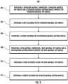
- FIG. 3 illustrates a flowchart 300 that contains example operations for providing an electrochemical gas sensor configured to measure electrolyte content.
- the flowchart 300 begins by providing a separator material (e.g., separator material 6) comprising a separator material top surface and a separator material bottom surface opposite the separator material top surface.
- a separator material e.g., separator material 6
- the flowchart 300 proceeds to disposing a first electrode (e.g., sensing electrode 4) on the separator material top surface.
- a first electrode e.g., sensing electrode
- the example flowchart 300 proceeds to disposing a second electrode (e.g., reference electrode 7) on the separator material bottom surface.
- a second electrode e.g., reference electrode
- the example flowchart 300 proceeds to providing a wick material (e.g., wick material 13) comprising a wick material top surface and a wick material bottom surface opposite the wick material top surface.
- a wick material e.g., wick material 13
- the example flowchart 300 proceeds to providing a third electrode (e.g., counter electrode 10) facing the wick material top surface.
- a third electrode e.g., counter electrode
- the example flowchart 300 proceeds to disposing a fourth electrode (e.g., auxiliary electrode 17, connecting wire 18) on the wick material bottom surface.
- a fourth electrode e.g., auxiliary electrode 17, connecting wire 18
- the separator material may be a first separator material
- the separator material top surface may be a first separator material top surface
- the separator material bottom surface may be a first separator material bottom surface.
- the example flowchart 300 may proceed to providing a second separator material (e.g., separator material 12) comprising a second separator material top surface and a second separator material bottom surface opposite the second separator material top surface.
- the example flowchart 300 may proceed to disposing the third electrode on the second separator material top surface.
- the example flowchart 300 may proceed to disposing the second separator material bottom surface on the wick material top surface.
- operations 302, 304, 306, and 308, 310, and 312 may not necessarily occur in the order depicted in FIG. 3 .
- one or more of the operations depicted in FIG. 3 may occur substantially simultaneously.
- one or more additional operations may be involved before, after, or between any of the operations shown in FIG. 3 .
- the method for manufacturing an apparatus for measuring electrolyte content in an electrochemical gas sensor is defined in the appended claim 11.
- FIG. 3 illustrates an example flowchart describing operations performed in accordance with example embodiments of the present disclosure.
- each block of the flowchart, and combinations of blocks in the flowchart may be implemented by various means, such as devices comprising hardware, firmware, one or more processors, and/or circuitry associated with execution of software comprising one or more computer program instructions.
- material handling equipment e.g., a robotic arm, servo motor, motion controllers, and the like
- computer program instructions residing on a non-transitory computer-readable storage memory.
- the computer program instructions which embody the procedures described above may be stored by a memory of an apparatus employing an embodiment of the present disclosure and executed by a processor of the apparatus.
- any such computer program instructions may be loaded onto a computer or other programmable apparatus (e.g., hardware) to produce a machine, such that the resulting computer or other programmable apparatus provides for implementation of the functions specified in the flowchart blocks.
- the instructions stored in the computer-readable storage memory produce an article of manufacture configured to implement the various functions specified in flowchart blocks.
- execution of a computer or other processing circuitry to perform various functions converts the computer or other processing circuitry into a particular machine configured to perform an example embodiment of the present disclosure.
- flowchart blocks support combinations of means for performing the specified functions and combinations of operations for performing the specified functions. It will also be understood that one or more flowchart blocks, and combinations of flowchart blocks, can be implemented by special purpose hardware-based computer systems which perform the specified functions, or combinations of special purpose hardware that execute computer instructions.
- certain ones of the operations herein may be modified or further amplified as described below. Moreover, in some embodiments additional optional operations may also be included. It should be appreciated that each of the modifications, optional additions or amplifications described herein may be included with the operations herein either alone or in combination with any others among the features described herein.
- example embodiments of the present disclosure thus provide for an electrochemical gas sensor configured to measure electrolyte content, monitor the drying of the wick material, and provide advance warning of impending failure, since the wick material may dry out before the one or more separators.
- the electrochemical gas sensor disclosed herein may easily and cost-effectively meet all of the performance requirements and also be sufficiently sensitive to detect failure and provide advance warning of impending failure, prediction of remaining life, or both.
Landscapes
- Chemical & Material Sciences (AREA)
- Health & Medical Sciences (AREA)
- Life Sciences & Earth Sciences (AREA)
- Analytical Chemistry (AREA)
- Physics & Mathematics (AREA)
- Electrochemistry (AREA)
- Chemical Kinetics & Catalysis (AREA)
- Biochemistry (AREA)
- General Health & Medical Sciences (AREA)
- General Physics & Mathematics (AREA)
- Immunology (AREA)
- Pathology (AREA)
- Molecular Biology (AREA)
- Investigating Or Analyzing Materials By The Use Of Electric Means (AREA)
Claims (11)
- Système de mesure de contenu d'électrolyte dans un capteur de gaz électrochimique (100), le système comprenant :
un boîtier (15), dans lequel est disposé :un matériau séparateur (6) comprenant une première surface de matériau séparateur et une deuxième surface de matériau séparateur opposée à la première surface de matériau séparateur ;une première électrode (4) disposée sur la première surface de matériau séparateur ;une deuxième électrode (7) disposée sur la deuxième surface de matériau séparateur ;un matériau de mèche (13) comprenant une première surface de matériau de mèche et une deuxième surface de matériau de mèche opposée à la première surface de matériau de mèche ;un électrolyte liquide disposé au moins dans le matériau de mèche (13) et le matériau séparateur (6) ;une troisième électrode (10) disposée sur la première surface de matériau de mèche ;une bande de film poreux en polytétrafluoroéthylène, PTFE (9) pour supporter et séparer électriquement la deuxième électrode (7) et la troisième électrode (10) ; etune quatrième électrode (17, 18) disposée sur la deuxième surface de matériau de mèche, dans lequel la quatrième électrode (17, 18) est configurée pour mesurer une conductivité électrique à travers le matériau de mèche (13),dans lequel le matériau séparateur (6) comprend un premier matériau hydrophile, dans lequel le matériau de mèche (13) comprend un deuxième matériau hydrophile, et dans lequel le premier matériau hydrophile est plus hydrophile que le deuxième matériau hydrophile. - Système selon la revendication 1, dans lequel la première électrode (4) est une électrode de détection, dans lequel la deuxième électrode (7) est une électrode de référence, dans lequel la troisième électrode (10) est une contre-électrode, et dans lequel la quatrième électrode (17, 18) est une électrode auxiliaire.
- Système selon l'une de la revendication 1 ou la revendication 2, dans lequel la quatrième électrode (18) est un fil-électrode.
- Système selon l'une quelconque des revendications 1 à 3, dans lequel la quatrième électrode (17) est une électrode de surface.
- Système selon l'une quelconque des revendications 1 à 4, dans lequel la quatrième électrode (17, 18) comprend du platine.
- Système selon l'une des revendications 1 à 5, dans lequel la quatrième électrode (17, 18) comprend du carbone.
- Système selon l'une des revendications 1 à 6, dans lequel la quatrième électrode (17, 18) est poreuse.
- Système selon l'une quelconque des revendications 1 à 7, dans lequel la quatrième électrode (18) est disposée sur une surface d'une bande de film (19) en polytétrafluoroéthylène, PTFE.
- Système selon l'une quelconque des revendications 1 à 8, dans lequel le matériau séparateur (6) est un premier matériau séparateur, et dans lequel le système comprend en outre un deuxième matériau séparateur (12) comprenant une troisième surface de matériau séparateur et une quatrième surface de matériau séparateur, dans lequel la troisième surface de matériau séparateur est configurée pour être disposée sur la troisième électrode (10), et la quatrième surface de matériau séparateur est configurée pour être disposée sur la première surface de matériau de mèche.
- Système selon l'une quelconque des revendications 1 à 9, dans lequel le système comprend en outre :un premier fil de connexion (5) configuré pour connecter la première électrode (6) à un premier contact électrique (16) ;un deuxième fil de connexion (8) configuré pour connecter la deuxième électrode (7) à un deuxième contact électrique (16) ;un troisième fil de connexion (11) configuré pour connecter la troisième électrode (10) à un troisième contact électrique (16) ;un quatrième fil de connexion (18) configuré pour connecter la quatrième électrode (17, 18) à un quatrième contact électrique (16).
- Procédé de fabrication d'un appareil de mesure de contenu d'électrolyte dans un capteur de gaz électrochimique (100), le procédé comprenant :la fourniture d'un boîtier (15) ;la fourniture, dans le boîtier (15), d'un matériau séparateur (6) comprenant une surface supérieure de matériau séparateur et une surface inférieure de matériau séparateur opposée à la surface supérieure de matériau séparateur ;la mise en place, dans le boîtier (15), d'une première électrode (4) sur la surface supérieure de matériau séparateur ;la mise en place, dans le boîtier (15), d'une deuxième électrode (7) sur la surface inférieure de matériau séparateur ;la fourniture, dans le boîtier (15), d'un matériau de mèche (13) comprenant une surface supérieure de matériau de mèche et une surface inférieure de matériau de mèche opposée à la surface supérieure de matériau de mèche ;la fourniture, au moins dans le matériau de mèche (13) et le matériau séparateur (6), d'un électrolyte liquide ;la fourniture, dans le boîtier (15), d'une troisième électrode (10) sur la surface supérieure de matériau mèche ;la fourniture, dans le boîtier (15), d'une bande de film poreux en polytétrafluoroéthylène, PTFE (9) pour supporter et séparer électriquement la deuxième électrode (7) et la troisième électrode (10) ; etla mise en place, dans le boîtier (15), d'une quatrième électrode (17, 18) sur la surface inférieure de matériau de mèche ;dans lequel le matériau séparateur (6) comprend un premier matériau hydrophile, dans lequel le matériau de mèche (13) comprend un deuxième matériau hydrophile, et dans lequel le premier matériau hydrophile est plus hydrophile que le deuxième matériau hydrophile.
Priority Applications (3)
| Application Number | Priority Date | Filing Date | Title |
|---|---|---|---|
| EP19163539.0A EP3712604B1 (fr) | 2019-03-18 | 2019-03-18 | Système et procédé de mesure de contenu d'électrolyte dans un capteur de gaz électrochimique |
| US16/817,999 US11307167B2 (en) | 2019-03-18 | 2020-03-13 | Systems and methods for measuring electrolyte content in an electrochemical gas sensor |
| CN202010190648.5A CN111707726A (zh) | 2019-03-18 | 2020-03-18 | 用于测量电化学气体传感器中电解质含量的系统和方法 |
Applications Claiming Priority (1)
| Application Number | Priority Date | Filing Date | Title |
|---|---|---|---|
| EP19163539.0A EP3712604B1 (fr) | 2019-03-18 | 2019-03-18 | Système et procédé de mesure de contenu d'électrolyte dans un capteur de gaz électrochimique |
Publications (2)
| Publication Number | Publication Date |
|---|---|
| EP3712604A1 EP3712604A1 (fr) | 2020-09-23 |
| EP3712604B1 true EP3712604B1 (fr) | 2024-12-18 |
Family
ID=65818378
Family Applications (1)
| Application Number | Title | Priority Date | Filing Date |
|---|---|---|---|
| EP19163539.0A Active EP3712604B1 (fr) | 2019-03-18 | 2019-03-18 | Système et procédé de mesure de contenu d'électrolyte dans un capteur de gaz électrochimique |
Country Status (3)
| Country | Link |
|---|---|
| US (1) | US11307167B2 (fr) |
| EP (1) | EP3712604B1 (fr) |
| CN (1) | CN111707726A (fr) |
Families Citing this family (3)
| Publication number | Priority date | Publication date | Assignee | Title |
|---|---|---|---|---|
| WO2017095612A1 (fr) * | 2015-12-01 | 2017-06-08 | Maxim Integrated Products, Inc. | Indicateur d'efficacité de stérilisation utilisant un enregistreur de données avec application logicielle/en nuage |
| CN111999367A (zh) * | 2020-09-27 | 2020-11-27 | 上海兆莹自控设备有限公司 | 气体检测仪电化学传感器剩余使用寿命的测算方法 |
| EP4488671B1 (fr) * | 2023-07-06 | 2026-02-25 | Hach Lange GmbH | Dispositif d'analyse d'ammonium |
Family Cites Families (13)
| Publication number | Priority date | Publication date | Assignee | Title |
|---|---|---|---|---|
| GB2075197B (en) * | 1980-04-30 | 1984-03-07 | City Tech | Electrochemical gas sensor |
| GB2292805B (en) * | 1994-08-26 | 1998-09-09 | Mil Ram Techn Inc | Method and apparatus for the detection of toxic gases |
| US6454923B1 (en) | 1997-11-10 | 2002-09-24 | Central Research Laboratories Limited | Gas sensor |
| DE19755506C2 (de) | 1997-12-13 | 2000-05-04 | Draeger Sicherheitstech Gmbh | Elektrochemischer Sensor mit offenem Gehäuse |
| GB9925591D0 (en) * | 1999-10-28 | 1999-12-29 | Secr Defence Brit | Electrochemical gas sensor assembly |
| GB2374419B (en) * | 2001-03-09 | 2004-12-29 | Zellweger Analytics Ltd | Electrochemical gas sensor |
| GB2436144A (en) * | 2006-03-15 | 2007-09-19 | Malcolm Robert Bullpitt | An electrochemical gas sensor having two electrodes formed on a common support |
| GB2468360A (en) * | 2009-03-06 | 2010-09-08 | Life Safety Distribution Ag | Ionic liquid electrolyte |
| US20110060202A1 (en) | 2009-09-08 | 2011-03-10 | Seth Adrian Miller | Dehydration detector using micro-needles |
| GB201014805D0 (en) * | 2010-09-07 | 2010-10-20 | Multi Sense Technologies Ltd | Microfluidics based assay device |
| US9689833B2 (en) * | 2011-10-11 | 2017-06-27 | Life Safety Distribution Ag | Auxiliary micro-electrodes for diagnostics of electrochemical gas sensors |
| CN109997034B (zh) * | 2016-09-30 | 2021-10-15 | 霍尼韦尔国际公司 | 用于电化学传感器中的电解质浓度测量的方法和设备 |
| US10782263B2 (en) * | 2017-05-04 | 2020-09-22 | Analog Devices Global | Systems and methods for determining the condition of a gas sensor |
-
2019
- 2019-03-18 EP EP19163539.0A patent/EP3712604B1/fr active Active
-
2020
- 2020-03-13 US US16/817,999 patent/US11307167B2/en active Active
- 2020-03-18 CN CN202010190648.5A patent/CN111707726A/zh active Pending
Also Published As
| Publication number | Publication date |
|---|---|
| US20200300807A1 (en) | 2020-09-24 |
| EP3712604A1 (fr) | 2020-09-23 |
| CN111707726A (zh) | 2020-09-25 |
| US11307167B2 (en) | 2022-04-19 |
Similar Documents
| Publication | Publication Date | Title |
|---|---|---|
| EP3901625B1 (fr) | Procédé et appareil de mesure de l'humidité à l'aide d'un capteur de gaz électrochimiques | |
| US11307167B2 (en) | Systems and methods for measuring electrolyte content in an electrochemical gas sensor | |
| US7217354B2 (en) | Method and apparatus for detection of chemical vapors | |
| US11085896B2 (en) | Auxiliary micro-electrodes for diagnostics of electrochemical gas sensors | |
| EP3695216B1 (fr) | Électrode d'étalonnage | |
| CN110114665B (zh) | 电解质浓度测量的方法和设备 | |
| US20240102958A1 (en) | Electrochemical gas sensor assembly | |
| AU2020290902A1 (en) | Interrogation of capillary-limited sensors | |
| Li et al. | Room temperature ionic-liquid electrochemical gas sensor array system for real-time mine safety monitoring | |
| JP5276604B2 (ja) | 電気化学式センサの診断方法及び電気化学式センサ | |
| AU2023397898A1 (en) | Interrogation and output correction of capillary-limited oxygen sensors | |
| WO2015070125A1 (fr) | Interface pour capteurs jetables | |
| EP4170335A1 (fr) | Appareils de détection électrochimique de gaz à faible sensibilité transversale | |
| CN223138854U (zh) | 一种气体压力检测装置 |
Legal Events
| Date | Code | Title | Description |
|---|---|---|---|
| PUAI | Public reference made under article 153(3) epc to a published international application that has entered the european phase |
Free format text: ORIGINAL CODE: 0009012 |
|
| STAA | Information on the status of an ep patent application or granted ep patent |
Free format text: STATUS: REQUEST FOR EXAMINATION WAS MADE |
|
| 17P | Request for examination filed |
Effective date: 20190318 |
|
| AK | Designated contracting states |
Kind code of ref document: A1 Designated state(s): AL AT BE BG CH CY CZ DE DK EE ES FI FR GB GR HR HU IE IS IT LI LT LU LV MC MK MT NL NO PL PT RO RS SE SI SK SM TR |
|
| AX | Request for extension of the european patent |
Extension state: BA ME |
|
| STAA | Information on the status of an ep patent application or granted ep patent |
Free format text: STATUS: EXAMINATION IS IN PROGRESS |
|
| 17Q | First examination report despatched |
Effective date: 20221031 |
|
| GRAP | Despatch of communication of intention to grant a patent |
Free format text: ORIGINAL CODE: EPIDOSNIGR1 |
|
| STAA | Information on the status of an ep patent application or granted ep patent |
Free format text: STATUS: GRANT OF PATENT IS INTENDED |
|
| INTG | Intention to grant announced |
Effective date: 20240716 |
|
| GRAS | Grant fee paid |
Free format text: ORIGINAL CODE: EPIDOSNIGR3 |
|
| GRAA | (expected) grant |
Free format text: ORIGINAL CODE: 0009210 |
|
| STAA | Information on the status of an ep patent application or granted ep patent |
Free format text: STATUS: THE PATENT HAS BEEN GRANTED |
|
| AK | Designated contracting states |
Kind code of ref document: B1 Designated state(s): AL AT BE BG CH CY CZ DE DK EE ES FI FR GB GR HR HU IE IS IT LI LT LU LV MC MK MT NL NO PL PT RO RS SE SI SK SM TR |
|
| REG | Reference to a national code |
Ref country code: CH Ref legal event code: EP |
|
| REG | Reference to a national code |
Ref country code: DE Ref legal event code: R096 Ref document number: 602019063565 Country of ref document: DE |
|
| REG | Reference to a national code |
Ref country code: IE Ref legal event code: FG4D |
|
| REG | Reference to a national code |
Ref country code: LT Ref legal event code: MG9D |
|
| PG25 | Lapsed in a contracting state [announced via postgrant information from national office to epo] |
Ref country code: HR Free format text: LAPSE BECAUSE OF FAILURE TO SUBMIT A TRANSLATION OF THE DESCRIPTION OR TO PAY THE FEE WITHIN THE PRESCRIBED TIME-LIMIT Effective date: 20241218 |
|
| PG25 | Lapsed in a contracting state [announced via postgrant information from national office to epo] |
Ref country code: FI Free format text: LAPSE BECAUSE OF FAILURE TO SUBMIT A TRANSLATION OF THE DESCRIPTION OR TO PAY THE FEE WITHIN THE PRESCRIBED TIME-LIMIT Effective date: 20241218 |
|
| PG25 | Lapsed in a contracting state [announced via postgrant information from national office to epo] |
Ref country code: BG Free format text: LAPSE BECAUSE OF FAILURE TO SUBMIT A TRANSLATION OF THE DESCRIPTION OR TO PAY THE FEE WITHIN THE PRESCRIBED TIME-LIMIT Effective date: 20241218 |
|
| PG25 | Lapsed in a contracting state [announced via postgrant information from national office to epo] |
Ref country code: NO Free format text: LAPSE BECAUSE OF FAILURE TO SUBMIT A TRANSLATION OF THE DESCRIPTION OR TO PAY THE FEE WITHIN THE PRESCRIBED TIME-LIMIT Effective date: 20250318 |
|
| REG | Reference to a national code |
Ref country code: NL Ref legal event code: MP Effective date: 20241218 |
|
| PG25 | Lapsed in a contracting state [announced via postgrant information from national office to epo] |
Ref country code: LV Free format text: LAPSE BECAUSE OF FAILURE TO SUBMIT A TRANSLATION OF THE DESCRIPTION OR TO PAY THE FEE WITHIN THE PRESCRIBED TIME-LIMIT Effective date: 20241218 Ref country code: GR Free format text: LAPSE BECAUSE OF FAILURE TO SUBMIT A TRANSLATION OF THE DESCRIPTION OR TO PAY THE FEE WITHIN THE PRESCRIBED TIME-LIMIT Effective date: 20250319 |
|
| PG25 | Lapsed in a contracting state [announced via postgrant information from national office to epo] |
Ref country code: RS Free format text: LAPSE BECAUSE OF FAILURE TO SUBMIT A TRANSLATION OF THE DESCRIPTION OR TO PAY THE FEE WITHIN THE PRESCRIBED TIME-LIMIT Effective date: 20250318 |
|
| PG25 | Lapsed in a contracting state [announced via postgrant information from national office to epo] |
Ref country code: NL Free format text: LAPSE BECAUSE OF FAILURE TO SUBMIT A TRANSLATION OF THE DESCRIPTION OR TO PAY THE FEE WITHIN THE PRESCRIBED TIME-LIMIT Effective date: 20241218 |
|
| REG | Reference to a national code |
Ref country code: AT Ref legal event code: MK05 Ref document number: 1752595 Country of ref document: AT Kind code of ref document: T Effective date: 20241218 |
|
| PG25 | Lapsed in a contracting state [announced via postgrant information from national office to epo] |
Ref country code: SM Free format text: LAPSE BECAUSE OF FAILURE TO SUBMIT A TRANSLATION OF THE DESCRIPTION OR TO PAY THE FEE WITHIN THE PRESCRIBED TIME-LIMIT Effective date: 20241218 |
|
| PG25 | Lapsed in a contracting state [announced via postgrant information from national office to epo] |
Ref country code: PL Free format text: LAPSE BECAUSE OF FAILURE TO SUBMIT A TRANSLATION OF THE DESCRIPTION OR TO PAY THE FEE WITHIN THE PRESCRIBED TIME-LIMIT Effective date: 20241218 |
|
| PG25 | Lapsed in a contracting state [announced via postgrant information from national office to epo] |
Ref country code: ES Free format text: LAPSE BECAUSE OF FAILURE TO SUBMIT A TRANSLATION OF THE DESCRIPTION OR TO PAY THE FEE WITHIN THE PRESCRIBED TIME-LIMIT Effective date: 20241218 |
|
| PG25 | Lapsed in a contracting state [announced via postgrant information from national office to epo] |
Ref country code: IS Free format text: LAPSE BECAUSE OF FAILURE TO SUBMIT A TRANSLATION OF THE DESCRIPTION OR TO PAY THE FEE WITHIN THE PRESCRIBED TIME-LIMIT Effective date: 20250418 |
|
| PG25 | Lapsed in a contracting state [announced via postgrant information from national office to epo] |
Ref country code: PT Free format text: LAPSE BECAUSE OF FAILURE TO SUBMIT A TRANSLATION OF THE DESCRIPTION OR TO PAY THE FEE WITHIN THE PRESCRIBED TIME-LIMIT Effective date: 20250421 |
|
| PG25 | Lapsed in a contracting state [announced via postgrant information from national office to epo] |
Ref country code: EE Free format text: LAPSE BECAUSE OF FAILURE TO SUBMIT A TRANSLATION OF THE DESCRIPTION OR TO PAY THE FEE WITHIN THE PRESCRIBED TIME-LIMIT Effective date: 20241218 |
|
| PG25 | Lapsed in a contracting state [announced via postgrant information from national office to epo] |
Ref country code: AT Free format text: LAPSE BECAUSE OF FAILURE TO SUBMIT A TRANSLATION OF THE DESCRIPTION OR TO PAY THE FEE WITHIN THE PRESCRIBED TIME-LIMIT Effective date: 20241218 Ref country code: RO Free format text: LAPSE BECAUSE OF FAILURE TO SUBMIT A TRANSLATION OF THE DESCRIPTION OR TO PAY THE FEE WITHIN THE PRESCRIBED TIME-LIMIT Effective date: 20241218 |
|
| PG25 | Lapsed in a contracting state [announced via postgrant information from national office to epo] |
Ref country code: SK Free format text: LAPSE BECAUSE OF FAILURE TO SUBMIT A TRANSLATION OF THE DESCRIPTION OR TO PAY THE FEE WITHIN THE PRESCRIBED TIME-LIMIT Effective date: 20241218 |
|
| PG25 | Lapsed in a contracting state [announced via postgrant information from national office to epo] |
Ref country code: CZ Free format text: LAPSE BECAUSE OF FAILURE TO SUBMIT A TRANSLATION OF THE DESCRIPTION OR TO PAY THE FEE WITHIN THE PRESCRIBED TIME-LIMIT Effective date: 20241218 |
|
| PG25 | Lapsed in a contracting state [announced via postgrant information from national office to epo] |
Ref country code: IT Free format text: LAPSE BECAUSE OF FAILURE TO SUBMIT A TRANSLATION OF THE DESCRIPTION OR TO PAY THE FEE WITHIN THE PRESCRIBED TIME-LIMIT Effective date: 20241218 |
|
| PG25 | Lapsed in a contracting state [announced via postgrant information from national office to epo] |
Ref country code: SE Free format text: LAPSE BECAUSE OF FAILURE TO SUBMIT A TRANSLATION OF THE DESCRIPTION OR TO PAY THE FEE WITHIN THE PRESCRIBED TIME-LIMIT Effective date: 20241218 |
|
| REG | Reference to a national code |
Ref country code: DE Ref legal event code: R097 Ref document number: 602019063565 Country of ref document: DE |
|
| PG25 | Lapsed in a contracting state [announced via postgrant information from national office to epo] |
Ref country code: DK Free format text: LAPSE BECAUSE OF FAILURE TO SUBMIT A TRANSLATION OF THE DESCRIPTION OR TO PAY THE FEE WITHIN THE PRESCRIBED TIME-LIMIT Effective date: 20241218 |
|
| PG25 | Lapsed in a contracting state [announced via postgrant information from national office to epo] |
Ref country code: MC Free format text: LAPSE BECAUSE OF FAILURE TO SUBMIT A TRANSLATION OF THE DESCRIPTION OR TO PAY THE FEE WITHIN THE PRESCRIBED TIME-LIMIT Effective date: 20241218 |
|
| REG | Reference to a national code |
Ref country code: CH Ref legal event code: H13 Free format text: ST27 STATUS EVENT CODE: U-0-0-H10-H13 (AS PROVIDED BY THE NATIONAL OFFICE) Effective date: 20251023 |
|
| PLBE | No opposition filed within time limit |
Free format text: ORIGINAL CODE: 0009261 |
|
| STAA | Information on the status of an ep patent application or granted ep patent |
Free format text: STATUS: NO OPPOSITION FILED WITHIN TIME LIMIT |
|
| PG25 | Lapsed in a contracting state [announced via postgrant information from national office to epo] |
Ref country code: LU Free format text: LAPSE BECAUSE OF NON-PAYMENT OF DUE FEES Effective date: 20250318 |
|
| 26N | No opposition filed |
Effective date: 20250919 |
|
| REG | Reference to a national code |
Ref country code: BE Ref legal event code: MM Effective date: 20250331 |
|
| PG25 | Lapsed in a contracting state [announced via postgrant information from national office to epo] |
Ref country code: BE Free format text: LAPSE BECAUSE OF NON-PAYMENT OF DUE FEES Effective date: 20250331 |
|
| PG25 | Lapsed in a contracting state [announced via postgrant information from national office to epo] |
Ref country code: CH Free format text: LAPSE BECAUSE OF NON-PAYMENT OF DUE FEES Effective date: 20250331 |
|
| PG25 | Lapsed in a contracting state [announced via postgrant information from national office to epo] |
Ref country code: IE Free format text: LAPSE BECAUSE OF NON-PAYMENT OF DUE FEES Effective date: 20250318 |
|
| PGFP | Annual fee paid to national office [announced via postgrant information from national office to epo] |
Ref country code: GB Payment date: 20260319 Year of fee payment: 8 |
|
| PGFP | Annual fee paid to national office [announced via postgrant information from national office to epo] |
Ref country code: DE Payment date: 20260320 Year of fee payment: 8 |
|
| PGFP | Annual fee paid to national office [announced via postgrant information from national office to epo] |
Ref country code: FR Payment date: 20260323 Year of fee payment: 8 |