EP3712743A1 - Dissipatives verbindungsmodul für erweiterungskarte mit m.2 formfaktor - Google Patents
Dissipatives verbindungsmodul für erweiterungskarte mit m.2 formfaktor Download PDFInfo
- Publication number
- EP3712743A1 EP3712743A1 EP20163438.3A EP20163438A EP3712743A1 EP 3712743 A1 EP3712743 A1 EP 3712743A1 EP 20163438 A EP20163438 A EP 20163438A EP 3712743 A1 EP3712743 A1 EP 3712743A1
- Authority
- EP
- European Patent Office
- Prior art keywords
- card
- dissipating
- electronic
- interconnection
- heat sink
- Prior art date
- Legal status (The legal status is an assumption and is not a legal conclusion. Google has not performed a legal analysis and makes no representation as to the accuracy of the status listed.)
- Granted
Links
Images


Classifications
-
- G—PHYSICS
- G06—COMPUTING OR CALCULATING; COUNTING
- G06F—ELECTRIC DIGITAL DATA PROCESSING
- G06F1/00—Details not covered by groups G06F3/00 - G06F13/00 and G06F21/00
- G06F1/16—Constructional details or arrangements
- G06F1/20—Cooling means
-
- G—PHYSICS
- G06—COMPUTING OR CALCULATING; COUNTING
- G06F—ELECTRIC DIGITAL DATA PROCESSING
- G06F1/00—Details not covered by groups G06F3/00 - G06F13/00 and G06F21/00
- G06F1/16—Constructional details or arrangements
- G06F1/20—Cooling means
- G06F1/206—Cooling means comprising thermal management
-
- G—PHYSICS
- G06—COMPUTING OR CALCULATING; COUNTING
- G06F—ELECTRIC DIGITAL DATA PROCESSING
- G06F1/00—Details not covered by groups G06F3/00 - G06F13/00 and G06F21/00
- G06F1/16—Constructional details or arrangements
- G06F1/18—Packaging or power distribution
- G06F1/183—Internal mounting support structures, e.g. for supporting printed circuit boards
- G06F1/185—Mounting of expansion boards
-
- G—PHYSICS
- G06—COMPUTING OR CALCULATING; COUNTING
- G06F—ELECTRIC DIGITAL DATA PROCESSING
- G06F1/00—Details not covered by groups G06F3/00 - G06F13/00 and G06F21/00
- G06F1/16—Constructional details or arrangements
- G06F1/18—Packaging or power distribution
- G06F1/183—Internal mounting support structures, e.g. for supporting printed circuit boards
- G06F1/187—Mounting of fixed or removable disk drives
-
- G—PHYSICS
- G06—COMPUTING OR CALCULATING; COUNTING
- G06F—ELECTRIC DIGITAL DATA PROCESSING
- G06F2200/00—Indexing scheme relating to G06F1/04 - G06F1/32
- G06F2200/20—Indexing scheme relating to G06F1/20
- G06F2200/201—Cooling arrangements using cooling fluid
Definitions
- the technical field of the invention is that of cooling modules for expansion cards.
- the present invention relates to a dissipating interconnection module allowing connection to an electronic board of an M.2 form factor expansion card and cooling of this expansion card and in particular of factor expansion cards.
- M.2 shape for calculation blades that can be mounted in the frame of a computer cabinet.
- Computing blades for computer cabinets can include, for example, processors, graphics cards, random access memory such as memory modules, mass storage such as hard disks. These computing blades are for example used to perform high performance computing, its elements therefore give off heat in operation and must be cooled to ensure their proper functioning and durability.
- fluidic cooling systems include, for example, pipes, most often made of copper, in which a fluid circulates. These pipes can be connected directly to the components to be cooled, for example by forming a loop around the components.
- the fluid can also circulate between two plates, for example of metal, at least one of the two plates being directly connected to a component to be cooled. It is also possible to solder channels inside a metal plate, for example copper, to pass the fluid there. The fluid can thus circulate in a metal plate connected to a component, for example along a memory module.
- FIG. 1 represents a cooling system according to the state of the art.
- the calories produced by the electronic component 11 are recovered by the heat sink 12 via a thermal pad and then transmitted to the fluidic cooling system 13 via the dry contact points 14.
- the heat sink 12 and the fluidic cooling system 13 are held together by screw 15 by dry contact. This makes the heat sink 12 removable, allowing access to the component 11.
- the only point of contact of the heat sink 12 with the fluidic cooling system 13 is therefore the point of dry contact 14.
- the fluidic cooling system 13 is also called a “cold plate” and may for example be made of metal, for example aluminum. This cold plate can for example run through the whole of the compute blade and at least some of the components of the compute blade can be connected to it.
- the electronic component 11 can for example be a memory module.
- the heat sink 12 of the Figure 1 is in thermal contact with component 11 when component 11 is connected to electronic card 1.
- the component is a hard drive, a Wi-Fi or Bluetooth network card or even a satellite navigation card accommodating a GPS antenna (according to the English name “Global Positioning System” literally translated as “Global Positioning System”).
- the M.2 form factor was created to support several options for small expansion cards, including SSDs (referred to as “Solid-State Drive”, solid-state drives), network maps or even satellite navigation maps.
- SSDs Solid-State Drive
- mSATA cannot scale to capacities greater than 1 Terabyte and maintain sufficient profitability.
- mSata connectors are bulky.
- the M.2 form factor also called NGFF (according to the Anglo-Saxon name “Next Generation Form Factor” literally translated as “New Generation Form Factor”) was created to maximize the use of space. an electronic card while reducing the connector footprint.
- expansion card is understood to mean an electronic card that can be connected to a computer module, for example to a computer cabinet, comprising a set of components making it possible to extend the capacities of the computer module.
- an expansion card can be an SSD disk, a memory module, a network card, a graphics card, a sound card, or any other electronic card that can be connected to a computer module.
- An M.2 form-factor expansion card must be in the upright position to be cooled using the state-of-the-art cooling system 10 shown.
- Figure 1 This is because the M.2 connector is located on one of the two 22-millimeter wide edges. On the opposite edge, a semicircular hole is drilled to allow fixing of the component on an electronic board 1. It is therefore complex and expensive to fix an M.2 form factor expansion board in a vertical position on a board. electronics 1.
- an M.2 form factor expansion card the most common dimensions are 22mm wide and 30mm long, 22mm x 42mm, 22mm x 60mm, 22mm x 80mm, and 22mm x 110mm. These dimensions imply a large footprint in height when it is connected to a card electronics 1 in vertical position. It is not possible to use such an expansion card in a vertical position in a computer rack mountable compute blade having a height of one rack unit (commonly called "1U"), that is, that is, 44.45 millimeters.
- 1U one rack unit
- the cooling system 10 of the prior art is not suitable for a horizontally mounted M.2 form factor expansion card, in particular because it is not possible to cool the two heating surfaces of the card. extension and removably securing the prior art system 10 while keeping the expansion board connected horizontally to electronic board 1.
- M.2 form factor expansion boards are not available. not hot-pluggable or hot-disconnectable.
- the invention provides a solution to the above-mentioned problems, by allowing efficient cooling of both surfaces of an M.2 form-factor expansion card and horizontal arrangement of the module, while allowing mounting and removal of the heatsink. thermal system of the invention without having to disconnect the M.2 form-factor expansion card and therefore without having to cut off the power supply to the electronic card to which it is connected.
- the invention it is possible to cool an M.2 form-factor expansion card while facilitating maintenance of both the inventive heat sink and the M.2 form-factor expansion card.
- the dissipating interconnection module according to the invention makes it possible to cool an M.2 expansion card thanks to the heat sink, and to connect the M.2 expansion card horizontally to an electronic card which realizes interconnection with the first electronic card to which the expansion card must be connected.
- This interconnection allows the M.2 expansion card to always be connected in the same arrangement, regardless of the arrangement of the motherboard connector, and therefore to be cooled always in the same arrangement.
- the envelope of the heat sink in thermal contact with the fluidic cooling system of the first electronic card and with the first heat exchange surface of the expansion card advantageously makes it possible to have the shortest thermal path between each surface d. thermal exchange of the M.2 expansion card and thermal cooling system.
- two elements are "in thermal contact”
- at least one surface of an element captures the heat emitted by the other surface, either by being in direct contact, or through a thermal interface.
- a thermal interface for example formed from a thermal paste or any other thermal material.
- a thermal interface is made of a thermal material, such as soft thermal paste.
- this soft thermal paste can include silicone.
- An advantage of using a soft thermal paste is that it is deformable. Thus, it is possible to have an optimal thermal contact while reducing the risk of damaging the components of the expansion card 30. In addition, by its deformable nature, compression of the thermal interface is thus possible, for achieve better thermal contact.
- the envelope has two tabs in thermal contact with the upper wall of the envelope and with the cooling system. These two tabs form with the upper wall of the casing a space arranged to receive the M.2 expansion card, and therefore advantageously allow the casing of the heat sink to envelop the M.2 expansion card to recover more of the heat emitted and to redirect it to the cooling system, while protecting the M.2 expansion card from possible shocks.
- the casing is inexpensive to manufacture since it only comprises a top wall and two legs. This enclosure alone can cool the M.2 expansion card, while having a small footprint in height.
- the electronic interconnection card is mechanically removably attached to the heat sink.
- This mechanical fixing is removable facilitates maintenance, advantageously allowing the dissipator to be detached. of the interconnection card without disconnecting the interconnection card from the first electronic card.
- the heat sink includes a mounting system for mechanically and removably securing the M.2 expansion card to the heat sink.
- this mechanical fastener is removable makes it possible to separate the heat sink from the M.2 expansion card, thus not having to disconnect the M.2 expansion card from the interconnection card.
- This makes it possible, for example, to carry out maintenance on the heat sink without disconnecting the M.2 expansion card from the interconnection electronic card and without disconnecting the electronic interconnection card from the first electronic card, thus making it possible to keep the electrical connection between the M.2 expansion card and the first electronic card.
- the heat sink of the heat sink interconnect module may further include a bottom wall in thermal contact with the legs of the heat sink casing, with the second heat exchange surface of the M.2 expansion card, and with the fluidic cooling system of the first electronic card.
- FIG. 2 shows a schematic representation of an exploded view of the dissipating interconnection module according to a first embodiment of the invention.
- the dissipating interconnection module 20 is shown schematically on Figure 2 in an exploded view in three dimensions along three axes x, y and z.
- Four marks are shown: A, B, E and F.
- the marks A and B each represent a view from one side, side A for mark A and side B for mark B.
- Mark E represents a view of below and the reference F represents a top view.
- the dissipating interconnection module 20 comprises an electronic interconnection card 22 and a heat sink comprising a casing 21.
- This interconnection module dissipant 20 ensures the cooling of an expansion card 30 with M.2 form factor thanks to the heat sink that it includes and, thanks to the electronic interconnection card that it includes, the interconnection of this card.
- 'extension 30 with a first electronic card 1 for example a motherboard, for example the motherboard of a computing blade mountable in the frame of a computer cabinet.
- this expansion card 30 with M.2 form factor can for example be an SSD disk (according to the English name “Solid-State Drive” for “semiconductor hard disk”) with M form factor. .2, or any other card to extend the capabilities of a computer module.
- the expansion card 30 comprises at least one first M.2 connector, for example a male M.2 connector configured to be connected to at least one second M.2 connector, for example a female M.2 connector.
- the expansion card 30 further comprises two heat exchange surfaces, a first heat exchange surface 303 and a second heat exchange surface 303.
- the expansion card 30 is a two-sided dissipating M.2 form-factor SSD, that is, each of its sides emits heat because it has components operating on each of its sides. its two sides, one side of the SSD is the first heat exchange surface and the other side is the second heat exchange surface.
- the M.2 form factor solid-state drive dissipates heat from one side only, that is, when it includes components only on one side, the heat dissipating side may be the first heat exchange surface or the second heat exchange surface. The other side of the SSD that does not dissipate heat is then the other heat exchange surface.
- the casing 21 of the dissipating interconnection module 20 comprises an upper wall 211 and two tabs 212.
- the wall 211 is called “upper” because in a preferred embodiment, when the dissipating interconnection module 20 is mechanically fixed in such a manner. removable on the upper surface, that is to say the surface facing the mark F, of a first electronic card in a horizontal position, the wall 211 is located above the expansion card 30 and the other components of the dissipating interconnection module 20, for example of the electronic interconnection card 22.
- upper to designate the wall 211 therefore refers to its position in the preferred embodiment relative to the other components of the dissipating interconnection module 20 as described previously.
- the upper wall 211 can for example be made of aluminum, copper, or any other thermally conductive material.
- Each of the two tabs 212 included in the casing 21 is in thermal contact with the upper wall 211.
- the two tabs 212 can for example be made of the same thermally conductive material as the upper wall 211.
- the two tabs 212 can for example be integral. of the upper wall 211, for example by having been formed by extrusion of material in a block of thermally conductive material.
- the two tabs 212 and the upper wall 211 are arranged so as to form a space suitable for receiving the expansion card.
- this arrangement is in the shape of a “U”, that is to say that the two tabs 212 each run along a longitudinal edge of the lower surface of the upper wall 211.
- “Lower surface” is understood to mean the surface of the wall.
- upper 211 turned towards the ground when the upper wall 211 is in a horizontal position along a horizontal plane along the longitudinal x and transverse y axes of the figure 2 .
- longitudinal edge is understood to mean an edge of the lower surface of the upper wall 211 along the longitudinal axis x of the figure 2 , that is to say one of the two longer edges of the lower surface of the upper wall 211, as shown in figure 2 .
- a tab 212 “runs along” a longitudinal edge when the tab 211 is parallel to this longitudinal edge.
- the tabs 212 may be perpendicular to the top wall 211 while being parallel to a longitudinal edge of the bottom surface of the top wall 211, as shown in Figure Figure 2 .
- the spacing between the two legs 211 is thus calculated to receive the expansion card 30 between the two legs 212.
- the spacing between the two legs 212 is therefore at least the width of the expansion card 30 when it is in a horizontal arrangement as shown in figure 2 , for example the width is at least 22 millimeters in the case of an M.2 form factor SSD.
- the height of the tabs 212 along the z axis is calculated to receive the expansion card 30, that is to say at least the thickness of the expansion card 30.
- the length of the upper wall 211 can also be calculated to receive the expansion card 30, for example in order to be in thermal contact with the entire first heat exchange surface of the expansion card 30.
- the top wall 211 will have a length greater than 80 millimeters, in order for example to be in thermal contact with the entire first heat exchange surface of the expansion card 30 and to have a sufficiently large surface to mechanically fix the electronic interconnection board 22.
- the first heat exchange surface 303 of the expansion card 30 is in thermal contact with the lower surface of the top wall 211.
- the casing 21 of the dissipating interconnection module 20 further comprises a mechanical fixing system 214 configured to mechanically removably secure the expansion card 30 to the heat sink of the dissipating interconnection module 20.
- the expansion card 30 is mechanically removably fixed by the fastening system 214 to the casing 21 of the heat sink.
- the term "removably fix” means being able to anchor the expansion card 30 to the casing 21 so that this anchoring is reversible, that is to say that the expansion card 30 can no longer be anchored to the casing 21.
- the fixing system 214 may for example comprise a screw comprising a thread and a hole in the casing 21 to accommodate the screw, the hole comprising an internal thread, thus making it possible to screw the screw into the hole and therefore to removably fix the expansion card 30 to the casing 21.
- the M.2 form factor of the expansion card requires the presence of a semicircular hole on the edge opposite the casing. edge where is the first M.2 connector. This hole allows the attachment of the expansion card by the screw of the fastening system 214.
- the mechanical fastening system 214 can include several tapped holes in the casing 21 to accommodate a screw, in order to be compatible with several lengths. of M.2 expansion cards 30.
- the mechanical fastening system 214 may have several holes, for example a hole for fixing a hard drive. M.2 SSD with a length of 80 millimeters, and another hole for attaching an M.2 SSD with a length of 100 millimeters. This allows compatibility with M.2 30 expansion cards of several lengths, and therefore to be able to keep the same enclosure 21 and the same dissipating interconnection module 20 while changing the M.2 30 expansion card for one. other M.2 30 expansion card of different length.
- the electronic interconnection card 22 of the dissipating interconnection module 20 comprises a second M.2 connector 221 for connection with the first M.2 connector 301 of the expansion card 30.
- the electronic interconnection card 22 can include an M.2 female connector 222, for connection with the M.2 male connector 301 of the expansion card 30.
- the electronic interconnection card 22 of the interconnection module dissipates 20 further comprises at least a third electrical connector 223 for connection with at least a fourth electrical connector 304 of the first electronic card, for example a motherboard.
- This third connector 223 can for example be a storage expansion connector when the expansion card 30 is an SSD disk.
- the connector 223 can then be an OCuLink® connector (according to the English name “Optical Copper Link” literally translated as “Optical Copper Link”, Cu being the chemical symbol for copper), a Thunderbolt connector ®, a PCI Express® connector, a SATA connector (according to the Anglo-Saxon name "Serial Advanced Technology Attachment”) or any other storage expansion connector.
- the fourth connector 304 of the first electronic card for example a motherboard, is a connector of the same type, configured to be connected to the third connector. For example, there is a storage expansion slot.
- the electronic interconnection card 22 is configured to be mechanically removably attached to the heat sink comprising the casing 21.
- the electronic interconnection card 22 can be fixed mechanically in a removable manner to the casing 21.
- the electronic card interconnection 22 comprises for example a fastening system 221 comprising for example two threaded screws.
- the fastening system 221 can also include a block comprising threaded holes, which can for example have the function of a nut.
- the block can accommodate the threaded screws, which can be screwed into the threaded holes of the block, thus mechanically fixing in a removable manner the electronic interconnection card 22 to the casing 21.
- This block can for example have a length equal to the width of the electronic interconnection card 22 and a width greater than the diameter of the largest tapped hole that it comprises. The size of this unit and its arrangement are such that it does not disturb the operation of the electronic interconnection card 22 and that it is not in contact with an electronic component of the electronic interconnection card 22.
- the dissipating interconnection module 20 is configured to be mechanically removably fixed to the first electronic card 1, for example to a motherboard.
- the dissipating interconnection module 20 comprises a mechanical fastening system, for example the mechanical fastening system 201.
- the mechanical fastening system 201 can for example comprise three threaded screws, each screw having a length of more than the height of the tabs 212 to be able to be screwed into the first electronic board 1 while passing through holes, for example three holes, included in the casing 21.
- the casing 21 may for example include two holes to accommodate two of the three screws of the fastening system 201 close to an edge of the upper wall 211 for example at the level of one end of the expansion card 30 as shown figure 2 .
- the casing may include a third hole to accommodate the third screw of the fastening system 201 close to an opposite edge of the upper wall 211, for example at the level of the electronic interconnection card 22 as shown in figure 2 .
- the electronic interconnection card 22 can also include a hole, aligned with the third hole of the upper wall 211, in order to mechanically removably fix the assembly of the dissipating interconnection module 20 to the first electronic card 1.
- FIG. 3 shows a schematic representation of the dissipating interconnection module 20 according to a first embodiment of the invention seen from below.
- bottom view is understood to mean a view along the reference E.
- the reference E represents a view of the surfaces facing the first electronic card 1 of the dissipating interconnection module 20 in a plane along the longitudinal x and transverse y axes, when the dissipating interconnection module 20 is removably mechanically fixed in a horizontal position to the upper surface of the first electronic card 1.
- the first electronic card 1 is not shown.
- the Figure 3 represents two references C and D, each reference representing a view of a face of the dissipating interconnection module 20.
- Reference C represents a view of face C and reference D represents a view of face D.
- the expansion card 30 is mechanically removably fixed to the casing 21 of the heat sink of the dissipating interconnection module 20 via the fixing system 214.
- the expansion card 30 is in thermal contact with the upper wall 211.
- the expansion card 30 is not in thermal contact with the lower surface of the legs 212 because this lower surface of the legs 212 is intended to be in thermal contact with the fluidic cooling system 13 as will be explained and shown in figures 5 and 6 .
- the term “lower surface” of the tabs 212 is understood to mean the surface visible in view from below of the tabs 212 when the dissipating interconnection module 20 is in the preferred embodiment, as shown in FIG. Figure 3 .
- the electronic interconnection card 22 is mechanically removably fixed to the casing 21 of the heat sink of the dissipating interconnection module 20 via the fixing system 221.
- the electronic interconnection card 22 may for example have the same width as the upper wall 211 of the casing 21 of the heat sink of the dissipating interconnection module 20. It may also include a fifth connector dedicated to the power supply. for connection with a sixth connector of the first electronic card 1 dedicated to the power supply.
- FIG. 4 shows a schematic representation of the dissipating interconnection module 20 according to a first embodiment of the invention in exploded front view.
- front view is understood to mean a view of the dissipating interconnection module 20 in a plane along the z and longitudinal x axes, according to the reference C.
- the electronic interconnection card 22 can for example be fixed mechanically in a removable manner to the casing 21 of the heat sink of the interconnection module dissipating 20 at its center along the longitudinal axis x. Indeed, the fact that the holes of the fixing system 221 are located at the level of the central axis of the electronic card makes it possible to leave room on the two ends of the card to place the third connector 223 and the M connector therein. .2 222.
- the figure 4 shows that the legs 212 of the casing 21 advantageously start at the level of the lower surface of the upper wall 211, in order to gain rigidity and solidity. Indeed, if the upper wall 211 and the legs 212 are not integral, the upper wall 211 thus rests on the upper surface of the legs 212 in the preferred embodiment.
- FIG. 5 shows a schematic representation of the dissipating interconnection module 20 according to a first embodiment of the invention seen from the side.
- side view is understood to mean a view according to one of the side marks A or B.
- Figure 5 shows a schematic representation of side A according to the mark A.
- the view of side A is opposite to the side view B of the dissipating interconnection module 20.
- the side view B being the view in the plane along the transverse axis y and along the z axis, on the side of the connector 223 and the electronic interconnection card 22.
- the figure 5 shows the dissipating interconnection module 20 when it is mechanically removably attached to the first electronic board 1.
- the dissipating interconnection module 20 is removably mechanically attached to a fluid cooling system 13 of the electronic board 1 by the fastening system 201 already presented above. This fluidic cooling system 13 is fixed to the first electronic card 1.
- the dissipating interconnection module 20 can be mechanically removably fixed directly to the electronic card 1, for example via holes made in the fluid cooling system 13 to allow the fixing system 201 to reach the first one. electronic card 1.
- the tabs 212 are in thermal contact with the fluid cooling system 13 and with the upper wall 211. As shown in figure 5 and in a preferred embodiment, the tabs 212 are integral with the upper wall 211.
- the legs 212 are in thermal contact with the fluidic cooling system 13
- the expansion card 30 is mechanically removably fixed to the casing 21 of the heat sink of the dissipating interconnection module 20 using the fixing system 214 presented above.
- the heat exchange surface 303 of the expansion card 30 is in thermal contact with the lower surface of the upper wall 211. In a preferred embodiment, and as shown in FIG. figure 5 , this thermal contact is made by a thermal interface.
- the heat exchange surface 302 of the expansion card 30 is advantageously in thermal contact with the fluidic cooling system 13.
- the dissipating interconnection module 20 thus makes it possible to cool the two heat exchange surfaces of the M.2 form factor expansion card 30 while allowing simple maintenance. Indeed, it suffices for an operator to use the fastening systems 201 and 214 to separate the casing 21 of the heat sink from the dissipating interconnection module 20 from the first electronic card 1, from the expansion card 30 and from the electronic interconnection card 22. This allows maintenance of the dissipating part of the dissipating interconnection module 20, that is to say of the heat sink, while keeping the extension card 30 connected to the first electronic card 1.
- This connection is made via the electronic card of interconnection 22 in order to be compatible with several types of connectors, for example when the first electronic card 1 does not include an M.2 connector, or when none of its M.2 connectors are available.
- this makes it possible, independently of the arrangement of the connector of the first electronic card 1, to have the same arrangement of the expansion card 30 when it is connected and therefore to be able to use the same form of heat sink in the module. dissipating interconnection 20.
- the shape of the casing 21 of the "U" heat sink also makes it possible to protect the expansion card 30. This also makes it possible to have the shortest thermal path between the heat exchange surface 303 of the card d. 'extension 30 and the fluidic cooling system 13 while having the expansion card 30 in horizontal arrangement along a plane along the longitudinal x and transverse y axes, in order to have a vertical footprint, therefore along the z axis, the less important possible.
- a thermal interface is interposed at the level of each thermal contact, as shown in FIG. figure 5 . That is, a thermal interface is present at each thermal contact, for example, a thermal interface 401 is present between a heat exchange surface of the expansion board 30 and the lower surface of the upper wall 211. For example, a thermal interface 403 is present between a tab 212 and the fluidic cooling system 13. For example, a thermal interface 402 is present between the expansion card 30 and the fluidic cooling system 13.
- FIG. 6 shows a schematic representation of the dissipating interconnection module 20 according to a second embodiment of the invention in partially exploded view.
- the dissipating interconnection module 20 is shown figure 6 in three dimensions along three axes x, y and z.
- partially exploded view is understood to mean a view in which all the elements are not in exploded view.
- the lower wall 23 is split from the rest of the dissipating interconnection module 20.
- the dissipating interconnection module 20 comprises a heat sink 50 comprising the casing 21 and a lower wall 23.
- the lower wall 23 comprises a central wall 231, two vertical walls 233 and two horizontal tabs 232.
- the two vertical walls 233 are in thermal contact with the central wall 231 and each horizontal wall 233 is in thermal contact with a horizontal tab 232.
- the bottom wall 23 is configured to be in thermal contact with the second heat exchange surface 302 of the expansion card 30, with each of the two tabs 212 of the casing 21 of the heat sink 50 and with the fluid cooling system. 13 of the first electronic card 1.
- the lower wall 23 comprises the same number of holes as the fixing system 201 comprises screws.
- the fastening system 201 comprises three screws and the lower wall 23 comprises three holes.
- the fixing system 201 can thus advantageously be used to mechanically removably fix the casing 21 to the bottom wall 23 instead of mechanically removably fixing the casing 21 to the first electronic card 1 as in the first embodiment.
- the dissipating interconnection module 20 can then be fixed mechanically in a removable manner to the first electronic card 1 by a fixing system, for example a fixing system comprising at least two screws.
- the at least two screws then mechanically removably fix the horizontal tabs 232 of the lower wall to the first electronic card 1 through the holes in the horizontal tabs 232.
- the casing 21 and the electronic interconnection card 22 being mechanically fixed in such a manner. removable to the lower wall 23, the dissipating interconnection module 20 is then mechanically removably attached to the first electronic card 1.
- the horizontal tabs 232, the vertical walls 233 and the central wall 231 of the lower wall 23 are integral, as shown in FIG. Figure 6 .
- the lower wall 23 is then one and the same part.
- the lower wall 23 may for example allow the thermal contact between the dissipating interconnection module 20 and the fluidic cooling system 13 to be offset, for example when the dissipating interconnection module 20 cannot be placed directly on the fluidic cooling system 13 for reasons of arrangement of the components on the first electronic card 1, for example on the motherboard of a computing blade.
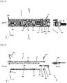
- FIG. 7 shows a schematic representation of the dissipating interconnection module 20 according to a second embodiment of the invention.
- the dissipating interconnection module 20 is shown figure 7 in three dimensions along three axes x, y and z.
- the dissipating interconnection module 20 at the figure 7 is shown when the lower wall 23 is mechanically removably fixed by the fastening system 201 to the casing 21 of the heat sink 50 and to the electronic interconnection card 22.
- FIG. 8 shows a schematic representation of the dissipating interconnection module 20 according to a second embodiment of the invention seen from the side.
- side view is understood to mean a view according to one of the side marks A or B.
- Figure 8 shows a schematic representation of side A according to the mark A.
- the view of side A is opposite to the side view B of the dissipating interconnection module 20.
- the side view B being the view in the plane along the transverse axis y and along the z axis, on the side of the connector 223 and the electronic interconnection card 22.
- the figure 8 shows the dissipating interconnection module 20 according to a second embodiment of the invention when it is mechanically removably attached to the first electronic card 1.
- the dissipating interconnection module 20 is removably mechanically attached to a system of fluidic cooling 13 of the electronic card 1 by the fastening system 201 already presented above. This fluidic cooling system 13 is fixed to the first electronic card 1.
- the dissipating interconnection module 20 When the dissipating interconnection module 20 according to the second embodiment of the invention is fixed mechanically in a removable manner to the first electronic card 1, for example by being mechanically fixed in a removable manner to the fluidic cooling system 13 as shown in figure 8 , the horizontal tabs 232 of the bottom wall 23 are in thermal contact with the fluid cooling system 13 and each horizontal tab is in thermal contact with a vertical wall 233. As shown in FIG. figure 8 and in a preferred embodiment, the tabs 233 are integral with the vertical walls 233.
- the lower wall 23 is then interposed between the casing 21 of the heat sink 50 and the fluidic cooling system 13 of the first electronic card 1.
- the horizontal legs 233 are in thermal contact with the fluidic cooling system 13
- This thermal contact makes it possible to redirect the heat emitted by the expansion card 30 captured by the central wall 231 of the lower wall 23 and by the upper wall 211 of the casing 21 towards the fluid cooling system 13.
- a thermal interface is interposed at the level of each thermal contact, as shown in FIG. figure 8 . That is, a thermal interface is present at each thermal contact, for example, a thermal interface 404 is present between each horizontal tab 232 and the fluidic cooling system 13.
- the lower wall 23 also makes it possible to have a “turnkey” solution for the installation of an expansion card 30 on a first electronic card 1 having little available space or for which the fluidic cooling system 13 is difficult to access. .
- This also makes it possible to have an expansion card 30 ready for use, the thermal contacts of the heat exchange surfaces of the expansion card 30 being already made by thermal interfaces inside the module. dissipating interconnection 20. It is then sufficient for an operator to make thermal contact of the horizontal tabs 232 with the fluidic cooling system 13, to mechanically removably fix the dissipating interconnection module 20 to the first electronic card 1 and to connect the connector 223 of the electronic card for interconnection to an ad hoc connector 304 of the first electronic card 1.
Landscapes
- Engineering & Computer Science (AREA)
- Theoretical Computer Science (AREA)
- Human Computer Interaction (AREA)
- Physics & Mathematics (AREA)
- General Engineering & Computer Science (AREA)
- General Physics & Mathematics (AREA)
- Computer Hardware Design (AREA)
- Power Engineering (AREA)
- Cooling Or The Like Of Electrical Apparatus (AREA)
Applications Claiming Priority (1)
| Application Number | Priority Date | Filing Date | Title |
|---|---|---|---|
| FR1902831A FR3094173B1 (fr) | 2019-03-19 | 2019-03-19 | Module d’interconnexion dissipant pour carte d'extension a facteur de forme m.2 |
Publications (2)
| Publication Number | Publication Date |
|---|---|
| EP3712743A1 true EP3712743A1 (de) | 2020-09-23 |
| EP3712743B1 EP3712743B1 (de) | 2023-08-16 |
Family
ID=68072518
Family Applications (1)
| Application Number | Title | Priority Date | Filing Date |
|---|---|---|---|
| EP20163438.3A Active EP3712743B1 (de) | 2019-03-19 | 2020-03-16 | Dissipatives verbindungsmodul für erweiterungskarte mit m.2 formfaktor |
Country Status (3)
| Country | Link |
|---|---|
| US (1) | US11275415B2 (de) |
| EP (1) | EP3712743B1 (de) |
| FR (1) | FR3094173B1 (de) |
Families Citing this family (6)
| Publication number | Priority date | Publication date | Assignee | Title |
|---|---|---|---|---|
| EP3923687B1 (de) | 2020-06-09 | 2024-04-03 | Samsung Electronics Co., Ltd. | Speichervorrichtung und elektronische vorrichtung damit |
| US11792957B2 (en) * | 2021-08-10 | 2023-10-17 | Dell Products L.P. | System for cooling of computing components of an information handling system |
| TWI773503B (zh) * | 2021-08-31 | 2022-08-01 | 英業達股份有限公司 | 智慧網卡的外殼 |
| US20230054055A1 (en) * | 2022-09-22 | 2023-02-23 | Intel Corporation | Mounting adaptor assemblies to support memory devices in server systems |
| CN117055717B (zh) * | 2023-10-12 | 2023-12-08 | 沐曦科技(北京)有限公司 | 一种扩展卡的散热系统 |
| US12560984B2 (en) * | 2023-10-26 | 2026-02-24 | Hewlett Packard Enterprise Development Lp | M.2 card adapter and heatsink |
Citations (3)
| Publication number | Priority date | Publication date | Assignee | Title |
|---|---|---|---|---|
| FR2966318A1 (fr) | 2010-10-13 | 2012-04-20 | Bull Sas | Dissipateur thermique pour module d'extension interchangeable pouvant etre connecte a une carte informatique |
| US20160335220A1 (en) * | 2014-04-25 | 2016-11-17 | Liqid Inc. | Stacked-device peripheral storage card |
| US10003153B1 (en) * | 2017-04-11 | 2018-06-19 | Giga-Byte Technology Co., Ltd. | Connector module |
Family Cites Families (19)
| Publication number | Priority date | Publication date | Assignee | Title |
|---|---|---|---|---|
| US7019974B2 (en) * | 2004-07-16 | 2006-03-28 | Hon Hai Precision Industry Co., Ltd. | Heat dissipation device |
| US8004841B2 (en) * | 2008-05-06 | 2011-08-23 | International Business Machines Corporation | Method and apparatus of water cooling several parallel circuit cards each containing several chip packages |
| US9342121B2 (en) * | 2008-05-06 | 2016-05-17 | International Business Machines Corporatoin | Cooling system for electronic components |
| CN201278345Y (zh) * | 2008-07-23 | 2009-07-22 | 鸿富锦精密工业(深圳)有限公司 | 导风装置 |
| CN201319174Y (zh) * | 2008-11-26 | 2009-09-30 | 鸿富锦精密工业(深圳)有限公司 | 导风装置 |
| US8027162B2 (en) * | 2009-09-24 | 2011-09-27 | International Business Machines Corporation | Liquid-cooled electronics apparatus and methods of fabrication |
| US8638559B2 (en) * | 2011-11-10 | 2014-01-28 | International Business Machines Corporation | User-serviceable liquid DIMM cooling system |
| US8587943B2 (en) * | 2011-11-28 | 2013-11-19 | International Business Machines Corporation | Liquid-cooling memory modules with liquid flow pipes between memory module sockets |
| US8659897B2 (en) * | 2012-01-27 | 2014-02-25 | International Business Machines Corporation | Liquid-cooled memory system having one cooling pipe per pair of DIMMs |
| US8913384B2 (en) * | 2012-06-20 | 2014-12-16 | International Business Machines Corporation | Thermal transfer structures coupling electronics card(s) to coolant-cooled structure(s) |
| US9089076B2 (en) * | 2012-07-06 | 2015-07-21 | International Business Machines Corporation | Cooling system for electronics |
| US9161475B2 (en) * | 2012-10-31 | 2015-10-13 | Hewlett-Packard Development Company, L.P. | Multi-function module for insertion into a networking chassis slot |
| US9068784B2 (en) * | 2012-11-15 | 2015-06-30 | International Business Machines Corporation | Cooling system for electronics |
| US9497888B2 (en) * | 2013-02-27 | 2016-11-15 | International Business Machines Corporation | Thermal transfer structure(s) and attachment mechanism(s) facilitating cooling of electronics card(s) |
| US9342116B2 (en) * | 2013-12-17 | 2016-05-17 | Giga-Byte Technology Co., Ltd. | Stacked expansion card assembly |
| US9443786B1 (en) * | 2015-08-19 | 2016-09-13 | Ac Propulsion, Inc. | Packaging and cooling method and apparatus for power semiconductor devices |
| TWM539644U (zh) * | 2016-11-15 | 2017-04-11 | 映奧股份有限公司 | 安裝多個m.2固態硬碟的儲存模組 |
| TWI626797B (zh) * | 2017-04-11 | 2018-06-11 | 技嘉科技股份有限公司 | 散熱器彈起結構及連接器模組 |
| TWI652568B (zh) * | 2018-01-30 | 2019-03-01 | 技嘉科技股份有限公司 | 電子裝置 |
-
2019
- 2019-03-19 FR FR1902831A patent/FR3094173B1/fr not_active Expired - Fee Related
-
2020
- 2020-03-16 EP EP20163438.3A patent/EP3712743B1/de active Active
- 2020-03-18 US US16/822,358 patent/US11275415B2/en active Active
Patent Citations (3)
| Publication number | Priority date | Publication date | Assignee | Title |
|---|---|---|---|---|
| FR2966318A1 (fr) | 2010-10-13 | 2012-04-20 | Bull Sas | Dissipateur thermique pour module d'extension interchangeable pouvant etre connecte a une carte informatique |
| US20160335220A1 (en) * | 2014-04-25 | 2016-11-17 | Liqid Inc. | Stacked-device peripheral storage card |
| US10003153B1 (en) * | 2017-04-11 | 2018-06-19 | Giga-Byte Technology Co., Ltd. | Connector module |
Also Published As
| Publication number | Publication date |
|---|---|
| FR3094173A1 (fr) | 2020-09-25 |
| US11275415B2 (en) | 2022-03-15 |
| US20200301488A1 (en) | 2020-09-24 |
| EP3712743B1 (de) | 2023-08-16 |
| FR3094173B1 (fr) | 2021-04-23 |
Similar Documents
| Publication | Publication Date | Title |
|---|---|---|
| EP3712743B1 (de) | Dissipatives verbindungsmodul für erweiterungskarte mit m.2 formfaktor | |
| EP2770810B1 (de) | Elektronische Karte, die mit einem Flüssigkeitskühlsystem versehen ist | |
| EP2628371B1 (de) | Kühlkörper für ein an eine computerplatine angeschlossenes auswechselbares expansionsmodul | |
| EP2773172B1 (de) | Mehrzahl von Kühlungsvorrichtungen und hydraulischer Verteiler | |
| FR3060202B1 (fr) | Dispositif de dissipation de chaleur d'une unite de controle multimedia | |
| FR3042886A1 (fr) | Equipement informatique avec bloc d'alimentation electrique refroidi | |
| FR3002411A1 (fr) | Dissipateur thermique pour processeur | |
| FR2670322A1 (fr) | Modules de memoire a etat solide et dispositifs de memoire comportant de tels modules. | |
| EP3220729A1 (de) | Elektronische vorrichtung und methode zum zusammenbau dieser vorrichtung | |
| EP3584620B1 (de) | Optische vorrichtung für fahrzeug, die mit einem heizelement ausgestattet ist | |
| FR2969379A1 (fr) | Refroidissement d'un equipement electronique | |
| WO2008049770A1 (fr) | Boitier electronique a cartes electroniques comportant des caloducs | |
| EP1884149A1 (de) | In schwierigen umgebungen arbeitende modulare elektronische vorrichtung | |
| FR2845821A1 (fr) | Substrat electronique d'un module electronique a trois dimensions a fort pouvoir de dissipation thermique et module electronique | |
| EP3712744B1 (de) | Kühlkörper für mehrere speicher-arrays | |
| EP4345577A1 (de) | Kühlkörper für eine berechnungsblatt-array-karte | |
| FR2737183A1 (fr) | Engin spatial avec dissipateur de chaleur | |
| EP4332728B1 (de) | Computerblade mit versetzten netzwerkkarten | |
| FR3126068A1 (fr) | Dispositif de rigidification d’un connecteur de type m.2 | |
| FR2920946A1 (fr) | Dispositif permettant d'evacuer la chaleur produite par des composants fixes sur des cartes enfichables disposees dans un boitier | |
| EP1950641B1 (de) | Elektrisches Versorgungsmodul für einem Chassis von Elektronikkarten | |
| EP2825929A1 (de) | Prozessor und heizkörper für diesen prozessor | |
| WO2017009226A1 (fr) | Dispositif électronique à échangeur thermique double | |
| FR2965141A1 (fr) | Carte electronique a refroidissement diphasique, equipement electronique incorporant une telle carte et aeronef incorporant un tel equipement | |
| WO2023227410A1 (fr) | Pièce de drainage thermique d'un module électronique 3d |
Legal Events
| Date | Code | Title | Description |
|---|---|---|---|
| PUAI | Public reference made under article 153(3) epc to a published international application that has entered the european phase |
Free format text: ORIGINAL CODE: 0009012 |
|
| STAA | Information on the status of an ep patent application or granted ep patent |
Free format text: STATUS: THE APPLICATION HAS BEEN PUBLISHED |
|
| AK | Designated contracting states |
Kind code of ref document: A1 Designated state(s): AL AT BE BG CH CY CZ DE DK EE ES FI FR GB GR HR HU IE IS IT LI LT LU LV MC MK MT NL NO PL PT RO RS SE SI SK SM TR |
|
| AX | Request for extension of the european patent |
Extension state: BA ME |
|
| STAA | Information on the status of an ep patent application or granted ep patent |
Free format text: STATUS: REQUEST FOR EXAMINATION WAS MADE |
|
| 17P | Request for examination filed |
Effective date: 20210315 |
|
| RBV | Designated contracting states (corrected) |
Designated state(s): AL AT BE BG CH CY CZ DE DK EE ES FI FR GB GR HR HU IE IS IT LI LT LU LV MC MK MT NL NO PL PT RO RS SE SI SK SM TR |
|
| STAA | Information on the status of an ep patent application or granted ep patent |
Free format text: STATUS: EXAMINATION IS IN PROGRESS |
|
| 17Q | First examination report despatched |
Effective date: 20210709 |
|
| GRAP | Despatch of communication of intention to grant a patent |
Free format text: ORIGINAL CODE: EPIDOSNIGR1 |
|
| STAA | Information on the status of an ep patent application or granted ep patent |
Free format text: STATUS: GRANT OF PATENT IS INTENDED |
|
| INTG | Intention to grant announced |
Effective date: 20230329 |
|
| P01 | Opt-out of the competence of the unified patent court (upc) registered |
Effective date: 20230330 |
|
| GRAS | Grant fee paid |
Free format text: ORIGINAL CODE: EPIDOSNIGR3 |
|
| GRAA | (expected) grant |
Free format text: ORIGINAL CODE: 0009210 |
|
| STAA | Information on the status of an ep patent application or granted ep patent |
Free format text: STATUS: THE PATENT HAS BEEN GRANTED |
|
| AK | Designated contracting states |
Kind code of ref document: B1 Designated state(s): AL AT BE BG CH CY CZ DE DK EE ES FI FR GB GR HR HU IE IS IT LI LT LU LV MC MK MT NL NO PL PT RO RS SE SI SK SM TR |
|
| REG | Reference to a national code |
Ref country code: CH Ref legal event code: EP Ref country code: DE Ref legal event code: R096 Ref document number: 602020015673 Country of ref document: DE |
|
| REG | Reference to a national code |
Ref country code: IE Ref legal event code: FG4D Free format text: LANGUAGE OF EP DOCUMENT: FRENCH |
|
| REG | Reference to a national code |
Ref country code: DE Ref legal event code: R081 Ref document number: 602020015673 Country of ref document: DE Owner name: COMMISSARIAT A L'ENERGIE ATOMIQUE ET AUX ENERG, FR Free format text: FORMER OWNER: BULL SAS, LES CLAYES-SOUS-BOIS, FR Ref country code: DE Ref legal event code: R081 Ref document number: 602020015673 Country of ref document: DE Owner name: COMMISSARIAT AE L'ENERGIE ATOMIQUE ET AUX ENER, FR Free format text: FORMER OWNER: BULL SAS, LES CLAYES-SOUS-BOIS, FR Ref country code: DE Ref legal event code: R081 Ref document number: 602020015673 Country of ref document: DE Owner name: BULL SAS, FR Free format text: FORMER OWNER: BULL SAS, LES CLAYES-SOUS-BOIS, FR |
|
| RAP2 | Party data changed (patent owner data changed or rights of a patent transferred) |
Owner name: COMMISSARIAT A L'ENERGIE ATOMIQUE ET AUX ENERGIES ALTERNATIVES Owner name: BULL SAS |
|
| REG | Reference to a national code |
Ref country code: LT Ref legal event code: MG9D |
|
| REG | Reference to a national code |
Ref country code: NL Ref legal event code: MP Effective date: 20230816 |
|
| REG | Reference to a national code |
Ref country code: AT Ref legal event code: MK05 Ref document number: 1600686 Country of ref document: AT Kind code of ref document: T Effective date: 20230816 |
|
| PG25 | Lapsed in a contracting state [announced via postgrant information from national office to epo] |
Ref country code: GR Free format text: LAPSE BECAUSE OF FAILURE TO SUBMIT A TRANSLATION OF THE DESCRIPTION OR TO PAY THE FEE WITHIN THE PRESCRIBED TIME-LIMIT Effective date: 20231117 |
|
| PG25 | Lapsed in a contracting state [announced via postgrant information from national office to epo] |
Ref country code: IS Free format text: LAPSE BECAUSE OF FAILURE TO SUBMIT A TRANSLATION OF THE DESCRIPTION OR TO PAY THE FEE WITHIN THE PRESCRIBED TIME-LIMIT Effective date: 20231216 |
|
| PG25 | Lapsed in a contracting state [announced via postgrant information from national office to epo] |
Ref country code: SE Free format text: LAPSE BECAUSE OF FAILURE TO SUBMIT A TRANSLATION OF THE DESCRIPTION OR TO PAY THE FEE WITHIN THE PRESCRIBED TIME-LIMIT Effective date: 20230816 Ref country code: RS Free format text: LAPSE BECAUSE OF FAILURE TO SUBMIT A TRANSLATION OF THE DESCRIPTION OR TO PAY THE FEE WITHIN THE PRESCRIBED TIME-LIMIT Effective date: 20230816 Ref country code: PT Free format text: LAPSE BECAUSE OF FAILURE TO SUBMIT A TRANSLATION OF THE DESCRIPTION OR TO PAY THE FEE WITHIN THE PRESCRIBED TIME-LIMIT Effective date: 20231218 Ref country code: NO Free format text: LAPSE BECAUSE OF FAILURE TO SUBMIT A TRANSLATION OF THE DESCRIPTION OR TO PAY THE FEE WITHIN THE PRESCRIBED TIME-LIMIT Effective date: 20231116 Ref country code: NL Free format text: LAPSE BECAUSE OF FAILURE TO SUBMIT A TRANSLATION OF THE DESCRIPTION OR TO PAY THE FEE WITHIN THE PRESCRIBED TIME-LIMIT Effective date: 20230816 Ref country code: LV Free format text: LAPSE BECAUSE OF FAILURE TO SUBMIT A TRANSLATION OF THE DESCRIPTION OR TO PAY THE FEE WITHIN THE PRESCRIBED TIME-LIMIT Effective date: 20230816 Ref country code: LT Free format text: LAPSE BECAUSE OF FAILURE TO SUBMIT A TRANSLATION OF THE DESCRIPTION OR TO PAY THE FEE WITHIN THE PRESCRIBED TIME-LIMIT Effective date: 20230816 Ref country code: IS Free format text: LAPSE BECAUSE OF FAILURE TO SUBMIT A TRANSLATION OF THE DESCRIPTION OR TO PAY THE FEE WITHIN THE PRESCRIBED TIME-LIMIT Effective date: 20231216 Ref country code: HR Free format text: LAPSE BECAUSE OF FAILURE TO SUBMIT A TRANSLATION OF THE DESCRIPTION OR TO PAY THE FEE WITHIN THE PRESCRIBED TIME-LIMIT Effective date: 20230816 Ref country code: GR Free format text: LAPSE BECAUSE OF FAILURE TO SUBMIT A TRANSLATION OF THE DESCRIPTION OR TO PAY THE FEE WITHIN THE PRESCRIBED TIME-LIMIT Effective date: 20231117 Ref country code: FI Free format text: LAPSE BECAUSE OF FAILURE TO SUBMIT A TRANSLATION OF THE DESCRIPTION OR TO PAY THE FEE WITHIN THE PRESCRIBED TIME-LIMIT Effective date: 20230816 Ref country code: AT Free format text: LAPSE BECAUSE OF FAILURE TO SUBMIT A TRANSLATION OF THE DESCRIPTION OR TO PAY THE FEE WITHIN THE PRESCRIBED TIME-LIMIT Effective date: 20230816 |
|
| PG25 | Lapsed in a contracting state [announced via postgrant information from national office to epo] |
Ref country code: PL Free format text: LAPSE BECAUSE OF FAILURE TO SUBMIT A TRANSLATION OF THE DESCRIPTION OR TO PAY THE FEE WITHIN THE PRESCRIBED TIME-LIMIT Effective date: 20230816 |
|
| PG25 | Lapsed in a contracting state [announced via postgrant information from national office to epo] |
Ref country code: ES Free format text: LAPSE BECAUSE OF FAILURE TO SUBMIT A TRANSLATION OF THE DESCRIPTION OR TO PAY THE FEE WITHIN THE PRESCRIBED TIME-LIMIT Effective date: 20230816 |
|
| PG25 | Lapsed in a contracting state [announced via postgrant information from national office to epo] |
Ref country code: SM Free format text: LAPSE BECAUSE OF FAILURE TO SUBMIT A TRANSLATION OF THE DESCRIPTION OR TO PAY THE FEE WITHIN THE PRESCRIBED TIME-LIMIT Effective date: 20230816 Ref country code: RO Free format text: LAPSE BECAUSE OF FAILURE TO SUBMIT A TRANSLATION OF THE DESCRIPTION OR TO PAY THE FEE WITHIN THE PRESCRIBED TIME-LIMIT Effective date: 20230816 Ref country code: ES Free format text: LAPSE BECAUSE OF FAILURE TO SUBMIT A TRANSLATION OF THE DESCRIPTION OR TO PAY THE FEE WITHIN THE PRESCRIBED TIME-LIMIT Effective date: 20230816 Ref country code: EE Free format text: LAPSE BECAUSE OF FAILURE TO SUBMIT A TRANSLATION OF THE DESCRIPTION OR TO PAY THE FEE WITHIN THE PRESCRIBED TIME-LIMIT Effective date: 20230816 Ref country code: DK Free format text: LAPSE BECAUSE OF FAILURE TO SUBMIT A TRANSLATION OF THE DESCRIPTION OR TO PAY THE FEE WITHIN THE PRESCRIBED TIME-LIMIT Effective date: 20230816 Ref country code: CZ Free format text: LAPSE BECAUSE OF FAILURE TO SUBMIT A TRANSLATION OF THE DESCRIPTION OR TO PAY THE FEE WITHIN THE PRESCRIBED TIME-LIMIT Effective date: 20230816 Ref country code: SK Free format text: LAPSE BECAUSE OF FAILURE TO SUBMIT A TRANSLATION OF THE DESCRIPTION OR TO PAY THE FEE WITHIN THE PRESCRIBED TIME-LIMIT Effective date: 20230816 |
|
| REG | Reference to a national code |
Ref country code: DE Ref legal event code: R081 Ref document number: 602020015673 Country of ref document: DE Owner name: COMMISSARIAT A L'ENERGIE ATOMIQUE ET AUX ENERG, FR Free format text: FORMER OWNER: BULL SAS, LES CLAYES-SOUS-BOIS, FR Ref country code: DE Ref legal event code: R081 Ref document number: 602020015673 Country of ref document: DE Owner name: COMMISSARIAT AE L'ENERGIE ATOMIQUE ET AUX ENER, FR Free format text: FORMER OWNER: BULL SAS, LES CLAYES-SOUS-BOIS, FR Ref country code: DE Ref legal event code: R081 Ref document number: 602020015673 Country of ref document: DE Owner name: BULL SAS, FR Free format text: FORMER OWNER: BULL SAS, LES CLAYES-SOUS-BOIS, FR |
|
| REG | Reference to a national code |
Ref country code: DE Ref legal event code: R097 Ref document number: 602020015673 Country of ref document: DE |
|
| REG | Reference to a national code |
Ref country code: GB Ref legal event code: 732E Free format text: REGISTERED BETWEEN 20240425 AND 20240501 |
|
| REG | Reference to a national code |
Ref country code: DE Ref legal event code: R081 Ref document number: 602020015673 Country of ref document: DE Owner name: COMMISSARIAT A L'ENERGIE ATOMIQUE ET AUX ENERG, FR Free format text: FORMER OWNERS: BULL SAS, LES CLAYES-SOUS-BOIS, FR; COMMISSARIAT AE L'ENERGIE ATOMIQUE ET AUX ENERGIES ALTERNATIVES, PARIS, FR Ref country code: DE Ref legal event code: R081 Ref document number: 602020015673 Country of ref document: DE Owner name: BULL SAS, FR Free format text: FORMER OWNERS: BULL SAS, LES CLAYES-SOUS-BOIS, FR; COMMISSARIAT AE L'ENERGIE ATOMIQUE ET AUX ENERGIES ALTERNATIVES, PARIS, FR |
|
| PLBE | No opposition filed within time limit |
Free format text: ORIGINAL CODE: 0009261 |
|
| STAA | Information on the status of an ep patent application or granted ep patent |
Free format text: STATUS: NO OPPOSITION FILED WITHIN TIME LIMIT |
|
| 26N | No opposition filed |
Effective date: 20240517 |
|
| PG25 | Lapsed in a contracting state [announced via postgrant information from national office to epo] |
Ref country code: IT Free format text: LAPSE BECAUSE OF FAILURE TO SUBMIT A TRANSLATION OF THE DESCRIPTION OR TO PAY THE FEE WITHIN THE PRESCRIBED TIME-LIMIT Effective date: 20230816 Ref country code: SI Free format text: LAPSE BECAUSE OF FAILURE TO SUBMIT A TRANSLATION OF THE DESCRIPTION OR TO PAY THE FEE WITHIN THE PRESCRIBED TIME-LIMIT Effective date: 20230816 |
|
| REG | Reference to a national code |
Ref country code: CH Ref legal event code: PL |
|
| PG25 | Lapsed in a contracting state [announced via postgrant information from national office to epo] |
Ref country code: BG Free format text: LAPSE BECAUSE OF FAILURE TO SUBMIT A TRANSLATION OF THE DESCRIPTION OR TO PAY THE FEE WITHIN THE PRESCRIBED TIME-LIMIT Effective date: 20230816 |
|
| PG25 | Lapsed in a contracting state [announced via postgrant information from national office to epo] |
Ref country code: LU Free format text: LAPSE BECAUSE OF NON-PAYMENT OF DUE FEES Effective date: 20240316 |
|
| PG25 | Lapsed in a contracting state [announced via postgrant information from national office to epo] |
Ref country code: MC Free format text: LAPSE BECAUSE OF FAILURE TO SUBMIT A TRANSLATION OF THE DESCRIPTION OR TO PAY THE FEE WITHIN THE PRESCRIBED TIME-LIMIT Effective date: 20230816 |
|
| PG25 | Lapsed in a contracting state [announced via postgrant information from national office to epo] |
Ref country code: MC Free format text: LAPSE BECAUSE OF FAILURE TO SUBMIT A TRANSLATION OF THE DESCRIPTION OR TO PAY THE FEE WITHIN THE PRESCRIBED TIME-LIMIT Effective date: 20230816 Ref country code: LU Free format text: LAPSE BECAUSE OF NON-PAYMENT OF DUE FEES Effective date: 20240316 Ref country code: BG Free format text: LAPSE BECAUSE OF FAILURE TO SUBMIT A TRANSLATION OF THE DESCRIPTION OR TO PAY THE FEE WITHIN THE PRESCRIBED TIME-LIMIT Effective date: 20230816 |
|
| REG | Reference to a national code |
Ref country code: BE Ref legal event code: MM Effective date: 20240331 |
|
| PG25 | Lapsed in a contracting state [announced via postgrant information from national office to epo] |
Ref country code: BE Free format text: LAPSE BECAUSE OF NON-PAYMENT OF DUE FEES Effective date: 20240331 |
|
| PG25 | Lapsed in a contracting state [announced via postgrant information from national office to epo] |
Ref country code: IE Free format text: LAPSE BECAUSE OF NON-PAYMENT OF DUE FEES Effective date: 20240316 |
|
| PG25 | Lapsed in a contracting state [announced via postgrant information from national office to epo] |
Ref country code: IE Free format text: LAPSE BECAUSE OF NON-PAYMENT OF DUE FEES Effective date: 20240316 Ref country code: BE Free format text: LAPSE BECAUSE OF NON-PAYMENT OF DUE FEES Effective date: 20240331 Ref country code: CH Free format text: LAPSE BECAUSE OF NON-PAYMENT OF DUE FEES Effective date: 20240331 |
|
| PG25 | Lapsed in a contracting state [announced via postgrant information from national office to epo] |
Ref country code: CY Free format text: LAPSE BECAUSE OF FAILURE TO SUBMIT A TRANSLATION OF THE DESCRIPTION OR TO PAY THE FEE WITHIN THE PRESCRIBED TIME-LIMIT; INVALID AB INITIO Effective date: 20200316 |
|
| PG25 | Lapsed in a contracting state [announced via postgrant information from national office to epo] |
Ref country code: HU Free format text: LAPSE BECAUSE OF FAILURE TO SUBMIT A TRANSLATION OF THE DESCRIPTION OR TO PAY THE FEE WITHIN THE PRESCRIBED TIME-LIMIT; INVALID AB INITIO Effective date: 20200316 |
|
| PG25 | Lapsed in a contracting state [announced via postgrant information from national office to epo] |
Ref country code: TR Free format text: LAPSE BECAUSE OF FAILURE TO SUBMIT A TRANSLATION OF THE DESCRIPTION OR TO PAY THE FEE WITHIN THE PRESCRIBED TIME-LIMIT Effective date: 20230816 |
|
| PGFP | Annual fee paid to national office [announced via postgrant information from national office to epo] |
Ref country code: GB Payment date: 20260324 Year of fee payment: 7 |
|
| PGFP | Annual fee paid to national office [announced via postgrant information from national office to epo] |
Ref country code: DE Payment date: 20260320 Year of fee payment: 7 |
|
| PGFP | Annual fee paid to national office [announced via postgrant information from national office to epo] |
Ref country code: FR Payment date: 20260325 Year of fee payment: 7 |