EP3714512B1 - Module en nid d'abeille - Google Patents
Module en nid d'abeille Download PDFInfo
- Publication number
- EP3714512B1 EP3714512B1 EP18804299.8A EP18804299A EP3714512B1 EP 3714512 B1 EP3714512 B1 EP 3714512B1 EP 18804299 A EP18804299 A EP 18804299A EP 3714512 B1 EP3714512 B1 EP 3714512B1
- Authority
- EP
- European Patent Office
- Prior art keywords
- honeycomb
- jumper
- busbar
- another
- plugs
- Prior art date
- Legal status (The legal status is an assumption and is not a legal conclusion. Google has not performed a legal analysis and makes no representation as to the accuracy of the status listed.)
- Active
Links
Images


Classifications
-
- H—ELECTRICITY
- H01—ELECTRIC ELEMENTS
- H01R—ELECTRICALLY-CONDUCTIVE CONNECTIONS; STRUCTURAL ASSOCIATIONS OF A PLURALITY OF MUTUALLY-INSULATED ELECTRICAL CONNECTING ELEMENTS; COUPLING DEVICES; CURRENT COLLECTORS
- H01R9/00—Structural associations of a plurality of mutually-insulated electrical connecting elements, e.g. terminal strips or terminal blocks; Terminals or binding posts mounted upon a base or in a case; Bases therefor
- H01R9/22—Bases, e.g. strip, block, panel
- H01R9/24—Terminal blocks
- H01R9/2408—Modular blocks
-
- H—ELECTRICITY
- H01—ELECTRIC ELEMENTS
- H01R—ELECTRICALLY-CONDUCTIVE CONNECTIONS; STRUCTURAL ASSOCIATIONS OF A PLURALITY OF MUTUALLY-INSULATED ELECTRICAL CONNECTING ELEMENTS; COUPLING DEVICES; CURRENT COLLECTORS
- H01R9/00—Structural associations of a plurality of mutually-insulated electrical connecting elements, e.g. terminal strips or terminal blocks; Terminals or binding posts mounted upon a base or in a case; Bases therefor
- H01R9/22—Bases, e.g. strip, block, panel
- H01R9/24—Terminal blocks
- H01R9/2458—Electrical interconnections between terminal blocks
Definitions
- the invention relates to a honeycomb module for forming a marshalling honeycomb, having a box-shaped housing with two end faces and four side faces which extend between the end faces, with at least two conductor entry openings being formed in each of the two end faces, each of which is assigned a conductor connection element arranged in the housing.
- the side surfaces each have at least one connecting element for connecting to another honeycomb module, the connecting elements being designed and arranged to correspond to one another on opposite side surfaces.
- electrical terminal blocks have been used for decades, which are usually snapped onto a mounting rail in a number next to one another, with a plurality of mounting rails equipped with terminal blocks in this way often being arranged in a control cabinet.
- a large number of electrical conductors have to be connected in a confined space
- marshalling patches are often used instead of terminal blocks, since a relatively large amount of space remains unused between the individual mounting rails.
- Marshalling honeycombs are known from practice in which a plurality of honeycomb modules are arranged in corresponding chambers of the frame within a fixed, rectangular assembly frame. Electrical conductors can be connected to the marshalling honeycomb or the individual honeycomb modules both from the front, the field side, and from the rear, the system side.
- conductor connection elements are arranged in the box-shaped housings of the individual honeycomb modules, which are usually connected to one another via corresponding conductor rails, so that an electrical conductor inserted through a corresponding conductor insertion opening in the front end face can be electrically connected to an electrical conductor or a connection contact that is inserted through a corresponding conductor entry opening in the rear face of the housing.
- Such a marshalling honeycomb with a plurality of honeycomb modules is for example from DE 195 12 226 A1 known.
- the individual honeycomb building blocks that are used in the individual chambers of the marshalling honeycomb all have the same dimensions.
- a mounting flange attachment is formed on the upper and lower edge side of the marshalling patch, via which the marshalling patch can be fastened to a mounting frame by means of screws.
- An adaptation of the marshalling patch to the individual wishes of the user is not possible with this known marshalling patch. If the number of conductors to be connected has to be increased, a correspondingly larger marshalling matrix with a greater number of individual honeycomb modules must be used, with marshalling cells with 18, 32, 48, 54 or 80 honeycomb modules being available in practice.
- a marshalling matrix which is characterized by increased flexibility and the possibility of adapting the marshalling matrix to individual wishes.
- the connecting elements which are formed on mutually opposite side faces, are formed and arranged so that they correspond to one another, so that the honeycomb building blocks can be connected directly to one another.
- the use of a rigid mounting frame that defines the number of individual honeycomb modules can be dispensed with, so that the marshalling honeycomb can in principle have any number of honeycomb modules
- a similar marshalling comb is also from the WO 2016/162463 A1 and the DE 20 2015 101 776 U1 known.
- These marshalling honeycombs also consist of a plurality of honeycomb building blocks which can be individually connected to one another and on the side faces of which locking elements which correspond to one another are formed.
- the closing elements have counter-locking elements that correspond to the locking elements of the honeycomb building blocks.
- the terminating elements can be used to fasten, mark or guide the conductors to be connected.
- WO 2016/162463 A1 discloses a honeycomb module according to the preamble of independent claim 1.
- honeycombs or honeycomb components are to be electrically connected to one another or the individual connections of a honeycomb component are to be electrically connected to one another, a conductor must be connected to the conductor connection elements to be connected. This then means that when two honeycomb modules are electrically connected to one another, one connection contact of a honeycomb module is required for the connection, so that the number of freely available conductor connection elements is correspondingly reduced by one in each case.
- the object of the present invention is therefore to provide a honeycomb module in which a potential distribution is possible in a simple manner.
- an electrical connection between two honeycomb modules should be able to be implemented easily, if necessary also subsequently.
- This task is a honeycomb module with the features of the characterizing part of the patent. This makes it possible, for example, to electrically connect two honeycomb modules arranged next to one another in a simple manner, simply by using a plug-in bridge that functions as a cross-bridge and has two plugs with its two plugs is plugged into a function shaft of a honeycomb module. The busbars contacted by the plugs are then electrically connected to one another via the plugs of the plug-in bridge, so that an electrical cross-connection is realized between the two honeycomb modules.
- the honeycomb module then has a total of four conductor entry openings, so that four conductor connection elements are also arranged in the housing, with the conductor connection elements assigned to one another being connected to one another, for example via a corresponding conductor rail, so that an electrical conductor inserted through the conductor entry opening in the front end face can be connected via the first conductor connection element, the busbar and the second conductor connection element to an electrical conductor which is inserted through the associated insertion opening in the rear end face of the housing.
- the honeycomb module can also have more than two conductor entry openings on both end faces, for example three, four, five, six or more conductor entry openings, so that a correspondingly larger number of conductor connection elements is then arranged in the housing.
- a number of function shafts corresponding to the number of conductor entry openings are then preferably formed on at least one end face and a corresponding number of busbars are also arranged in the housing, which are electrically connected to the conductor connection elements and are accessible via the function shafts for a plug of a jumper.
- a transverse bridging between two adjacent honeycomb modules can be realized in a simple manner by the design of the functional shafts and the corresponding arrangement of the conductor rails.
- the honeycomb module according to the invention not only is cross-bridging to an adjacent honeycomb module possible, but also bridging of the individual potentials of a honeycomb module.
- At least one function shaft is dimensioned in such a way that two plugs of two jumpers can be inserted one behind the other into the functional shaft in the direction in which the associated busbar extends.
- the opening in the busbar is dimensioned according to one embodiment of the invention in such a way that two plugs of two plug-in bridges one behind the other in the direction of extension of the busbar into the opening can be inserted.
- the opening thus has a length that corresponds to the width of two plugs of two jumpers.
- two separate openings in the direction of extension of the busbar can be arranged one behind the other in the busbar, so that a plug of one jumper can then be plugged into one opening and a plug of the other jumper can be plugged into the other opening.
- the housing has a frame-like, hollow outer housing and at least two inner housings arranged next to one another therein.
- the connecting elements for connecting the honeycomb module to other honeycomb modules are formed on the outer housing.
- the conductor insertion openings and the at least one functional shaft are formed in the individual inner housings, and the conductor connection elements are arranged.
- Each inner housing preferably has a conductor insertion opening on the front and a conductor insertion opening on the back, with two conductor connection elements electrically connected to one another then also being arranged in the inner housing.
- Such a configuration of the honeycomb module has the advantage that an outer housing can be optionally combined with different inner housings.
- inner housings can thus be arranged next to one another, for example in an outer housing.
- the as slide-in elements trained inner housing each have their own potential and can be firmly connected to each other and to the outer housing via corresponding locking elements.
- an inner housing has at least one conductor entry opening both on its front and on its rear, each of which is assigned a conductor connection element
- a function shaft is formed only on the front or on the rear.
- a function shaft it is also possible for a function shaft to be formed both in the front and in the rear of the honeycomb module or the inner housing, so that a jumper can be connected both from the front and from the rear, i.e. from the field side or from the system side , can be plugged into the honeycomb module.
- a recess is formed on at least one edge region of at least one end face, which recess is arranged adjacent to a functional shaft.
- the honeycomb module has an outer housing and a plurality of inner housings
- the at least one recess is formed in the outer housing.
- a recess is preferably formed in each of two opposite edge regions, so that in the case of a transverse bridging with adjacent honeycomb modules on both sides, the rail strip of a plug-in bridge can be inserted into the recess.
- a holding element is also preferably formed on at least one edge region of an end face, which together with a corresponding holding element of a second, adjacently arranged honeycomb module forms a retaining groove for a marker plate.
- each honeycomb module does not have its own retaining groove for a marker plate, but rather a retaining groove is formed by two honeycomb modules arranged next to one another. Since connecting elements for connecting to an adjacent honeycomb module are formed on the side faces of the honeycomb modules, there is a certain distance between the connection areas of two honeycomb modules arranged next to one another, which is thus used as a fastening location for a marking plate.
- a holding element is formed as a part of the holding groove at the transition area of the end face to the side face, which faces the adjacent honeycomb module.
- At least one groove and at least one web corresponding to the groove are formed as connecting elements on each side surface of the honeycomb modules, with the individual grooves and the individual webs each extending parallel to the longitudinal extent of the respective side surface.
- the webs and the grooves preferably each have a dovetail-shaped cross section, so that two honeycomb building blocks connected to one another in this way can be displaced relative to one another perpendicularly to the longitudinal extent of the grooves and webs.
- the at least one groove on a side face of a honeycomb module is arranged mirror-symmetrically to the web on the opposite side face of the honeycomb module, so that when two honeycomb modules are connected to one another, a web on a side face of one honeycomb module fits into the corresponding groove on the opposite side face of the other honeycomb module intervenes. At the same time forms a groove on a side face of one honeycomb module together with a web on the opposite side face of the other honeycomb module also creates a corresponding mechanical connection. There are then at least two connections, in particular at least two tongue and groove connections, between two honeycomb modules connected to one another.
- a honeycomb module By forming at least one connecting element on all four side faces of the honeycomb modules, with the connecting elements that are formed on opposite side faces being designed to correspond to one another, a honeycomb module can be connected to another honeycomb module both in the x-direction and in the y-direction and adjacent honeycomb modules of a marshalling honeycomb are fixed relative to each other both in the x-direction and in the y-direction.
- locking elements are preferably provided on the honeycomb building block, which are arranged on at least two adjacent side surfaces of the honeycomb building blocks. Because at least one locking element is arranged on two adjacent side faces of the honeycomb modules, two honeycomb modules can also be fixed to one another in the z-direction, regardless of whether the second honeycomb module is arranged next to the first honeycomb module in the x-direction or in the y-direction becomes.
- the latching elements are preferably designed as latching lugs, so that the fixing or latching between two adjacent honeycomb building blocks takes place in that the latching lug of one honeycomb building block is brought into engagement with the latching lug of the adjacent honeycomb building block.
- two honeycomb modules to be connected to one another must be arranged in relation to one another in such a way that they face one another with a side face on which a latching element is formed in each case.
- the side surfaces on which the latching lugs are arranged are preferably designed to be resilient.
- the latching elements can also be designed as latching arms, on the free ends of which at least one latching lug is arranged in each case.
- a displacement of two honeycomb modules against each other in the longitudinal extension (z-direction) of the respective side surfaces is preferably prevented in the marshalling honeycomb or the honeycomb modules in that two latching elements are arranged on at least two adjacent side surfaces of the honeycomb modules.
- the two latching elements are arranged next to one another viewed in the longitudinal extension of the respective side surface, with the latching elements extending in opposite directions.
- the latching elements are designed and arranged in such a way that their ends overlap somewhat in the longitudinal extension. If two honeycomb modules are connected to one another, in which two such latching elements are arranged on the opposite side surfaces, the result is that the two latching element pairs formed by the total of four latching elements cross in the middle of the side surfaces of the honeycomb modules. It is then no longer possible to move two honeycomb modules connected to one another in this way parallel to the longitudinal extension of the two opposite side surfaces, so that the two honeycomb modules are also securely latched to one another in the z-direction.
- the invention also relates to a marshalling honeycomb with a plurality of interconnected honeycomb modules according to the invention.
- the design of the individual honeycomb modules each with at least two functional shafts creates the possibility of electrically conductively connecting several honeycomb modules to one another within the marshalling honeycomb.
- a jumper with two plugs is used, with one plug of the jumper being plugged into a function shaft of two adjacent honeycomb modules, so that the two plugs of the jumper each contact a busbar in a honeycomb module and thereby the two busbars are electrically connected to each other.
- a plug-in bridge can be used as a plug-in bridge, as is basically known from the prior art.
- Such a plug-in bridge has, in particular, two plugs that are connected to one another via a rail strip, so that the plug-in bridge is designed in a U-shape overall.
- the jumper has an insulating head, which can also be used as a Handle section is used for the jumper.
- the individual plugs of the jumper can consist of parallel contact legs arranged next to one another, of which at least one is preferably designed to be resilient, so that the plugs make resilient contact with the corresponding openings in the busbars.
- Such plug-in bridges are known in principle, in particular for use in terminal blocks.
- the transverse bridging between two adjacent honeycomb modules of a marshalling honeycomb does not take place by means of a plug-in bridge but by means of a U-shaped, electrically conductive connecting element.
- a U-leg of the connecting element is inserted into a functional shaft of two adjacent honeycomb modules, so that the two U-legs of the connecting element each contact a busbar in a honeycomb module and the two busbars are thus electrically connected to one another.
- a connecting element can be stamped out very easily from an electrically conductive flat material and bent accordingly.
- a jumper with a plurality of plugs can preferably also be inserted into the function shafts of at least one honeycomb module, with the plugs of the jumper connecting several busbars of the Connect the honeycomb module to each other electrically.
- the honeycomb module preferably has a number of functional shafts corresponding to the number of conductor insertion openings on an end face and a corresponding number of busbars connected to the conductor connection elements, so that all potentials of the honeycomb module can be connected to one another via a jumper with a corresponding number of plugs.
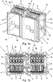
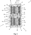
- honeycomb blocks 1 side by side ( 1 and 2 ) or one above the other ( 3 ) are arranged and thus form a marshalling matrix 2.
- a marshalling honeycomb 2 will generally have more than just two honeycomb modules 1, for example four, eight, sixteen or even more of the same type or different honeycomb modules.
- the individual honeycomb building blocks 1 can be arranged relative to one another in such a way that each honeycomb building block 1 is connected to at least one other honeycomb building block 1 both in the x direction and in the y direction.
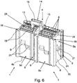
- the individual honeycomb modules 1 each have a box-shaped housing 3 with two end faces 4a, 4b and four side faces 5a, 5b, 5c and 5d.
- the individual side faces 5a, 5b, 5c, 5d extend between the two end faces 4a, 4b and each have an angle of 90° to the end faces 4a, 4b.
- a honeycomb module 1 thus has an essentially rectangular cross-section, in the present case the individual honeycomb modules 1 are even of square design and have the same dimensions, but without the invention being restricted thereto.
- the honeycomb building blocks 1 have a length or depth that runs in the longitudinal extension of the respective side surfaces 5a, 5b, 5c, 5d—and thus in the z direction, which is the same for the two honeycomb building blocks 1 shown.
- the invention is not limited to this either, i. H. individual honeycomb building blocks can also have different depths.
- a plurality of conductor insertion openings 6 are formed on the front end face 4a of the honeycomb modules 1, through which a conductor to be connected can be inserted into a conductor connection element 7 arranged inside the housing 3.
- the conductor connection elements 7 are designed as clamping springs, so that the conductor connection elements 7 are spring clamp connections.
- conductor connection elements with a different connection technology for example screw terminals or spring-cage terminals, can also be used.
- a stripped conductor inserted through a conductor insertion opening 6 is clamped by the clamping spring against a conductor rail which is connected to a second conductor connection element which is accessible through a conductor insertion opening formed on the rear side 4b of the honeycomb module 1.
- the honeycomb building blocks 1 have a plurality of connecting elements 8, 9 on all four side faces 5a, 5b, 5c, 5d.
- a honeycomb module 1 can be connected to another honeycomb module 1 on all four side surfaces 5a, 5b, 5c, 5d and thus both in the x-direction and in the y-direction in order to form a corresponding marshalling honeycomb 2.
- the honeycomb building blocks 2 have on all four side faces 5a, 5b, 5c, 5d each have a dovetail-shaped groove 8 and a dovetail-shaped web 9 as connecting elements.
- the groove 8 on a side surface 5a, 5b, 5c, 5d is arranged mirror-symmetrically to the web 9 on the opposite side surface 5c, 5d, 5a, 5b, so that when two honeycomb modules 1 are connected to one another, the groove 8 and the webs 9 of one side surface 5a of one honeycomb module 1 with the web 9 and the groove 8 of the opposite side surface 5c of the adjacent honeycomb module 1 are engaged.
- both the grooves 8 and the webs 9 each extend parallel to the longitudinal extent of the respective side surface 5a, 5b, 5c, 5d
- the connection of two honeycomb modules 1 to one another takes place in that the honeycomb modules 1 with their respective opposing grooves 8 and webs 9 in z-direction are pushed into each other, as in 4 is shown.
- the assembly direction thus runs parallel to the longitudinal extent of the side surfaces 5a, 5b, 5c, 5d.
- the mounting direction also corresponds to the direction of insertion of the conductors into the conductor insertion openings 6.
- a plurality of function shafts 10 are formed in the end face 4a of the two honeycomb modules 1 , the number of function shafts 10 corresponding to the number of conductor insertion openings 6 in the end face 4a of the honeycomb module 1 .
- five functional shafts 10 are also provided here, as shown in particular in FIG Fig. 1b is evident.
- a corresponding number of busbars 11 are arranged in the housing 3 in the area of the function shafts 10 and are each electrically conductively connected to a conductor connection element 7 .
- an opening 12 is formed in the busbars 11 in such a way that it corresponds to the respective function shaft 10 such that a plug 13 of a jumper 14 can be inserted through a function shaft 10 into the opening 12 in the corresponding busbar 11 .
- the two honeycomb modules 1 connected to one another are electrically connected to one another via a first plug-in bridge 14 having two plugs 13 .
- a second jumper 24 is inserted, each having five plugs 23 .
- the individual plugs 13 of the jumper 14 or the two plugs 23 of the jumper 24 are each connected to one another via a rail strip, the rail strips being covered by an insulating head 15, 25.
- the housing 3 has a frame-like, hollow outer housing 16 and a plurality of inner housings 17 arranged next to one another therein.
- a total of five disk-shaped inner housings 17 are arranged next to one another in the frame-like outer housing 16, with a conductor entry opening 6 being formed on the front and rear of each inner housing 17 and two conductor connection elements 7 assigned to the conductor entry openings 6 being arranged inside the inner housing 17.
- a function shaft 10 is formed in the front of the inner housing 17, through which the conductor rail 11, which is also arranged in the inner housing 17, is accessible.
- the individual inner housings 17 functioning as plug-in elements thus inherently each have their own potential, ie they are not electrically connected to one another.
- the function shafts 10 of the inner housings 17 arranged next to one another are arranged on a line which runs parallel to the edge of the end face 4a.
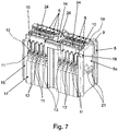
- the individual functional shafts 10 are dimensioned such that two plugs 13 , 23 of two jumpers 14 , 24 can be inserted one behind the other into the functional shaft 10 in the direction of extension E of the associated busbar 11 .
- the functional shafts 10 thus have a length that corresponds to the width of two plugs 13, 23. So that the two plugs 13, 23 of two jumpers 14, 24 can both contact a busbar 11, the opening 12 in the busbar 11 is dimensioned such that both plugs 13, 23 are inserted one behind the other in the direction E of the busbar 11 into the opening 12 can be ( 7 ).
- the first jumper 14 has only two plugs 13, while the second jumper 24 has a number of plugs 23 corresponding to the number of function shafts 10 of the honeycomb module 1, in the present case five plugs 23 ( figure 5 ).
- the functional shafts 10 are designed in the end faces 4a of the honeycomb modules 1 in such a way that the plug-in bridges 24 can each be inserted far enough into the functional shafts 10 that their rail strip or insulating head 25 does not protrude beyond the end face 4a of the honeycomb modules 1. So that this is also possible with a plug-in jumper 14 connecting two honeycomb modules 1, a recess 18 is formed on two opposite edge regions of the end face 4a, which are arranged adjacent to the functional shafts 10, so that the rail strip or the insulating head 15 of the plug-in jumper 14 can dip into the recess 18. The plugged-in jumpers 14, 24 then do not protrude beyond the end face 4a of the honeycomb modules 1.
- holding elements 19 are formed on the edge regions of the end face 4a of the honeycomb building blocks, which together with the corresponding holding elements 19 of the adjacent honeycomb building block 1 form a holding groove 20 into which a marker plate can be snapped.
- the retaining elements 19 are preferably formed on all four edge regions of both end faces 4a, 4b, so that corresponding marking labels can be attached both to the front, the field side, of the honeycomb building blocks 1 and to their rear, the contact side.
- the marking plates can then be attached to the honeycomb building blocks 1 either in the x-direction and/or in the y-direction. From a comparison of 2 and 3 It can also be seen that, depending on the arrangement of the honeycomb modules 1, the cross bridging by means of the jumpers 14, 24 can take place in the x-direction or in the y-direction.
- the individual honeycomb building blocks 1 are firmly connected to one another in the x-direction and y-direction in that the individual dovetail-shaped webs 9 are pushed into the corresponding grooves 8 .
- displacement of the honeycomb building blocks 1 relative to one another in the z-direction is prevented by the grooves 8 and webs 9 are not prevented, since the grooves 8 and webs 9 all extend parallel to the longitudinal extension of the respective side surface 5a, 5b, 5c, 5d and stops or edges that would limit displacement in the z-direction are not provided.
- the honeycomb components 1 in the embodiment shown have two locking elements 21 designed as locking lugs on their individual side surfaces 5a, 5b, 5c, 5d.
- the latching elements 21 each extend in the longitudinal extension of the respective side surface 5a, 5b, 5c, 5d, the two latching elements 21 formed on one side surface being arranged next to one another in the longitudinal extension of the respective side surface 5a, 5b, 5c, 5d and extending in opposite directions. Since the ends of the locking elements 21 overlap in the longitudinal direction, the end of one locking element 21 is arranged somewhat further back in the z-direction and the end of the other locking element 21 is arranged somewhat further forward.
- the Figures 5 to 7 illustrate how a plug-in bridge 14 for the cross connection between the two honeycomb modules 1 can be inserted into two honeycomb modules 1 arranged next to one another, which are connected to one another via the corresponding grooves 8 and webs 9 and are also fixed to one another via the locking elements 21 in the z-direction.
- a jumper 24 can also be inserted into each of the two honeycomb modules 1, via which the individual conductor connection elements 7 in the individual inner housings 17 can be bridged.
- FIG 8 shows an alternative embodiment of the two honeycomb modules 1 according to FIG 2 or. 7 , wherein the cross-bridging of the two honeycomb modules 1 does not take place via a jumper 14 but via an electrically conductive connecting element 22 .
- the connecting element 22 is essentially U-shaped, with the two U-legs 26 of the connecting element 22 each being inserted into a functional shaft 10 of the two adjacent honeycomb modules 1 .
- the ends of the U-legs 26 of the connecting element 22 are bent in such a way that they extend parallel to the busbars 11 .
- an opening 27 is formed in each of the ends of the U-legs 26, into which a plug 23 of a jumper 24 is inserted.
Landscapes
- Catalysts (AREA)
- Connector Housings Or Holding Contact Members (AREA)
- Filtering Materials (AREA)
Claims (14)
- Module en nid d'abeilles (1) pour la formation d'une matrice de répartition (2), comprenant un boîtier (3) en forme de caisson comprenant deux faces frontales (4a, 4b) et quatre faces latérales (5a, 5b, 5c, 5d) qui s'étendent entre les faces frontales (4a, 4b),au moins deux ouvertures d'introduction de conducteurs (6) étant formées respectivement dans les deux faces frontales (4a, 4b), auxquelles est respectivement associé un élément de raccordement de conducteur (7) agencé dans le boîtier (3),les faces latérales (5a, 5b, 5c, 5d) présentant respectivement au moins un élément de liaison (8, 9) pour la liaison avec un autre module en nid d'abeilles (1), et les éléments de liaison (8, 9) étant formés et agencés en correspondance les uns des autres sur des faces latérales (5a, 5c ; 5b, 5d) opposées les unes aux autres ;au moins deux barres conductrices (11) étant agencées dans le boîtier (3), une barre conductrice (11) étant respectivement reliée de manière électriquement conductrice à un élément de raccordement de conducteur (7),caractériséen ce qu'au moins deux puits fonctionnels (10) sont formés dans au moins une face frontale (4a), eten ce qu'au moins une ouverture (12) correspondant à un puits fonctionnel (10) est formée respectivement dans les au moins deux barres conductrices (11), de telle sorte qu'un connecteur (13, 23) d'un pont enfichable (14, 24) peut être enfiché par le biais d'un puits fonctionnel (10) dans la face frontale (4a) dans l'ouverture (12) dans une barre conductrice (11).
- Module en nid d'abeilles (1) selon la revendication 1, caractérisé en ce qu'au moins un puits fonctionnel (10) est dimensionné de telle sorte que deux connecteurs (13, 23) de deux ponts enfichables (14, 15) peuvent être enfichés l'un derrière l'autre dans le puits fonctionnel (10) dans la direction d'extension (E) de la barre conductrice associée (11).
- Module en nid d'abeilles (1) selon la revendication 2, caractérisé en ce qu'une ouverture (12) dans au moins une barre conductrice (11) est dimensionnée de telle sorte que deux connecteurs (13, 23) de deux ponts enfichables (14, 24) peuvent être enfichés l'un derrière l'autre dans l'ouverture (12) dans la barre conductrice (11) dans la direction d'extension (E) de la barre conductrice associée (11) ou en ce que deux ouvertures sont agencées l'une derrière l'autre dans la direction d'extension (E) de la barre conductrice (11) dans au moins une barre conductrice (11).
- Module en nid d'abeilles (1) selon l'une quelconque des revendications 1 à 3, caractérisé en ce que le boîtier (3) présente un boîtier extérieur (16) creux en forme de cadre et au moins deux boîtiers intérieurs (17) agencés côte à côte dans celui-ci, en ce que les éléments de liaison (8, 9) sont formés sur le boîtier extérieur (16), et en ce que, respectivement, les ouvertures d'introduction de conducteurs (6) et l'au moins un puits fonctionnel (10) sont formés, et les éléments de raccordement de conducteurs (7) sont agencés dans les boîtiers intérieurs individuels (17).
- Module en nid d'abeilles (1) selon l'une quelconque des revendications 1 à 4, caractérisé en ce qu'un évidement (18) est formé sur au moins une zone de bord d'au moins une face frontale (4a), lequel est agencé au voisinage d'un puits fonctionnel (10), de telle sorte que la barrette de rail (15) d'un pont enfichable (14) peut être introduite dans l'évidement (18).
- Module en nid d'abeilles (1) selon les revendications 4 et 5, caractérisé en ce que l'au moins un évidement (18) est formé dans le boîtier extérieur (16).
- Module en nid d'abeilles (1) selon l'une quelconque des revendications 1 à 6, caractérisé en ce qu'au moins un élément de retenue (19) est formé sur au moins une zone de bord de la face frontale (4a), lequel forme une rainure de retenue (20) conjointement avec un élément de retenue correspondant (19) d'un deuxième module en nid d'abeilles (1) agencé au voisinage.
- Module en nid d'abeilles (1) selon les revendications 4 et 7, caractérisé en ce que les puits fonctionnels (10) sont agencés au voisinage des éléments de retenue (19) et en ce que les puits fonctionnels (10) de plusieurs boîtiers intérieurs (17) agencés côte à côte sont agencés sur une ligne qui s'étend de préférence parallèlement au bord de la face frontale (4a).
- Module en nid d'abeilles (1) selon l'une quelconque des revendications 1 à 8, caractérisé en ce qu'au moins un élément d'encliquetage (21) est agencé respectivement sur au moins deux faces latérales (5a, 5b, 5c, 5d) adjacentes l'une à l'autre du module en nid d'abeilles (1), les éléments d'encliquetage (21) s'étendant respectivement dans la direction de l'extension longitudinale de la face latérale respective (5a, 5b, 5c, 5d).
- Matrice de répartition (2) comprenant plusieurs modules en nid d'abeilles (1) reliés entre eux selon l'une quelconque des revendications 1 à 9.
- Matrice de répartition (2) selon la revendication 10, comprenant un pont enfichable (14) comprenant deux connecteurs (13), caractérisée en ce qu'un connecteur (13) du pont enfichable (14) est enfiché respectivement dans un puits fonctionnel (10) de deux modules en nid d'abeilles (1) voisins, et en ce que les deux connecteurs (13) du pont enfichable (14) viennent respectivement en contact avec une barre conductrice (11) dans un module en nid d'abeilles (1), de telle sorte que les deux barres conductrices (11) sont reliées électriquement entre elles.
- Matrice de répartition (2) selon la revendication 10, comprenant un élément de liaison électriquement conducteur en forme de U (22), caractérisée en ce que respectivement une branche de U (26) de l'élément de liaison (22) est enfichée dans un puits fonctionnel (10) de deux modules en nid d'abeilles voisins (1), et en ce que les deux branches de U (26) de l'élément de liaison (22) viennent respectivement en contact avec une barre conductrice (11) dans un module en nid d'abeilles (1), de telle sorte que les deux barres conductrices (11) sont reliées électriquement entre elles.
- Matrice de répartition (2) selon la revendication 11 ou 12, caractérisée en ce qu'un pont enfichable (24) comprenant plusieurs connecteurs (23) est enfiché dans les puits fonctionnels (10) d'au moins un module en nid d'abeilles (1), les connecteurs (23) du pont enfichable (24) reliant électriquement entre elles plusieurs barres conductrices (11) du module en nid d'abeilles (1).
- Matrice de répartition (2) selon les revendications 12 et 13, caractérisée en ce que les extrémités des branches de U (26) de l'élément de liaison (22) sont pliées de telle sorte qu'elles s'étendent parallèlement aux barres conductrices (11) et en ce qu'une ouverture (27) est formée respectivement dans les extrémités des branches de U (26), dans laquelle est enfiché un connecteur (13, 23) d'un pont enfichable (14, 24).
Applications Claiming Priority (2)
| Application Number | Priority Date | Filing Date | Title |
|---|---|---|---|
| DE102017127243.7A DE102017127243A1 (de) | 2017-11-20 | 2017-11-20 | Wabenbaustein |
| PCT/EP2018/081525 WO2019096977A1 (fr) | 2017-11-20 | 2018-11-16 | Module en nid d'abeille |
Publications (2)
| Publication Number | Publication Date |
|---|---|
| EP3714512A1 EP3714512A1 (fr) | 2020-09-30 |
| EP3714512B1 true EP3714512B1 (fr) | 2022-06-08 |
Family
ID=64332313
Family Applications (1)
| Application Number | Title | Priority Date | Filing Date |
|---|---|---|---|
| EP18804299.8A Active EP3714512B1 (fr) | 2017-11-20 | 2018-11-16 | Module en nid d'abeille |
Country Status (5)
| Country | Link |
|---|---|
| EP (1) | EP3714512B1 (fr) |
| CN (1) | CN111344906B (fr) |
| DE (1) | DE102017127243A1 (fr) |
| ES (1) | ES2922491T3 (fr) |
| WO (1) | WO2019096977A1 (fr) |
Families Citing this family (3)
| Publication number | Priority date | Publication date | Assignee | Title |
|---|---|---|---|---|
| DE102020122398A1 (de) * | 2020-08-27 | 2022-03-03 | Voith Patent Gmbh | Elektrokontaktkupplung für spurgeführte fahrzeuge |
| DE102021123890A1 (de) * | 2021-09-15 | 2023-03-16 | WAGO Verwaltungsgesellschaft mit beschränkter Haftung | Leiteranschlussklemme |
| EP4487422A4 (fr) * | 2022-03-04 | 2026-01-14 | Honeywell Int Inc | Bloc de borne auxiliaire destiné à être utilisé avec un module électronique |
Family Cites Families (11)
| Publication number | Priority date | Publication date | Assignee | Title |
|---|---|---|---|---|
| DE19512226A1 (de) | 1995-03-27 | 1996-10-02 | Wago Verwaltungs Gmbh | Rangierwabe für elektrische Rangierverteiler |
| DE202004000523U1 (de) * | 2004-01-15 | 2005-05-25 | Weidmüller Interface GmbH & Co. KG | Anschlußsystem zum Anschluß elektrischer Leiter an ein elektrisches Gerät |
| DE102011113333B4 (de) * | 2011-09-15 | 2014-07-03 | Phoenix Contact Gmbh & Co. Kg | Elektrische Reihenklemme und Reihenklemmenblock |
| DE202012013526U1 (de) * | 2012-05-11 | 2017-06-16 | Phoenix Contact Gmbh & Co. Kg | Elektrische Reihenklemme |
| DE102013004666A1 (de) * | 2013-03-19 | 2014-09-25 | Phoenix Contact Gmbh & Co. Kg | Klemmenblockanordnung |
| DE102014101528A1 (de) | 2014-02-07 | 2015-08-13 | Phoenix Contact Gmbh & Co. Kg | Wabenbaustein und Rangierwabe |
| DE102015105545A1 (de) * | 2015-04-10 | 2016-10-13 | Phoenix Contact Gmbh & Co. Kg | Rangierwabe |
| DE202015101776U1 (de) | 2015-04-10 | 2015-07-15 | Phoenix Contact Gmbh & Co. Kg | Rangierwabe |
| DE202016100323U1 (de) * | 2016-01-25 | 2017-04-28 | Wago Verwaltungsgesellschaft Mbh | Querverbinder für Reihenklemmen |
| DE102016106479A1 (de) * | 2016-04-08 | 2017-10-12 | Phoenix Contact Gmbh & Co. Kg | Rangierwabe |
| DE102016119061B4 (de) * | 2016-10-07 | 2021-06-10 | Phoenix Contact Gmbh & Co. Kg | Rangierwabe mit gebildeter Haltenut für Markierungsschilder und Wabenbaustein |
-
2017
- 2017-11-20 DE DE102017127243.7A patent/DE102017127243A1/de not_active Withdrawn
-
2018
- 2018-11-16 EP EP18804299.8A patent/EP3714512B1/fr active Active
- 2018-11-16 WO PCT/EP2018/081525 patent/WO2019096977A1/fr not_active Ceased
- 2018-11-16 ES ES18804299T patent/ES2922491T3/es active Active
- 2018-11-16 CN CN201880075158.1A patent/CN111344906B/zh active Active
Also Published As
| Publication number | Publication date |
|---|---|
| CN111344906A (zh) | 2020-06-26 |
| ES2922491T3 (es) | 2022-09-15 |
| CN111344906B (zh) | 2022-01-14 |
| EP3714512A1 (fr) | 2020-09-30 |
| DE102017127243A1 (de) | 2019-05-23 |
| WO2019096977A1 (fr) | 2019-05-23 |
Similar Documents
| Publication | Publication Date | Title |
|---|---|---|
| DE102013113975C5 (de) | Halterahmen für einen Steckverbinder | |
| EP1507315B1 (fr) | Pont à fiche pour des borniers électriques et borniers associées | |
| EP3490075B1 (fr) | Ensemble composé de connecteur enfichable et d'élément de retenue ainsi que connecteur enfichable et élément de retenue correspondant | |
| EP3353859B1 (fr) | Dispositif de connexion pour conducteur | |
| DE102016106481B3 (de) | Rangierwabe | |
| EP3375048B1 (fr) | Contact à enficher | |
| DE202016104790U1 (de) | Steckverbinder | |
| EP3281254B1 (fr) | Système de rangement en nid d'abeille | |
| WO2012055847A1 (fr) | Unité de raccordement électrique | |
| DE102009030645B4 (de) | Brückerelement und Set aus zumindest einem Klemmelement und Brückerelement | |
| EP3714512B1 (fr) | Module en nid d'abeille | |
| DE102016119061B4 (de) | Rangierwabe mit gebildeter Haltenut für Markierungsschilder und Wabenbaustein | |
| DE102005050399B3 (de) | Anschlussklemme für Leiterplatten | |
| DE19706636C2 (de) | Elektrische Anschlußvorrichtung für in einer Reihe angeordnete Verbraucher, insbesondere Magnetventile | |
| EP3440745B1 (fr) | Alvéole de connexion pour construire un bloc d'alvéoles, bloc d'alvéoles et outil pour enlever un alvéole de connexion du bloc d'alvéoles | |
| EP3281253B1 (fr) | Système de rangement en nid d'abeille | |
| DE102012015037B4 (de) | Elektronikmodul | |
| EP3281252B1 (fr) | Module en nid d'abeille | |
| DE202015105021U1 (de) | Anschlussgehäuse mit einer Anschlussvorrichtung für Leiter | |
| DE202004006125U1 (de) | Verteilerleiste | |
| DE102013003389B4 (de) | Baugruppe bestehend aus mindestens zwei benachbart zueinander angeordneten elektrischen Anschlussklemmen und einem Querverbinder | |
| WO2022117390A1 (fr) | Agencement de bornier conducteur de protection et d'au moins un connecteur transversal, bornier conducteur de protection et agencement de barre omnibus | |
| DE102004047515B4 (de) | Gehäuse | |
| DE102023132109A1 (de) | Sensor-Aktor-Verteiler | |
| EP4556724A1 (fr) | Collecteur d'actionneur de capteur |
Legal Events
| Date | Code | Title | Description |
|---|---|---|---|
| STAA | Information on the status of an ep patent application or granted ep patent |
Free format text: STATUS: UNKNOWN |
|
| STAA | Information on the status of an ep patent application or granted ep patent |
Free format text: STATUS: THE INTERNATIONAL PUBLICATION HAS BEEN MADE |
|
| PUAI | Public reference made under article 153(3) epc to a published international application that has entered the european phase |
Free format text: ORIGINAL CODE: 0009012 |
|
| STAA | Information on the status of an ep patent application or granted ep patent |
Free format text: STATUS: REQUEST FOR EXAMINATION WAS MADE |
|
| 17P | Request for examination filed |
Effective date: 20200513 |
|
| AK | Designated contracting states |
Kind code of ref document: A1 Designated state(s): AL AT BE BG CH CY CZ DE DK EE ES FI FR GB GR HR HU IE IS IT LI LT LU LV MC MK MT NL NO PL PT RO RS SE SI SK SM TR |
|
| AX | Request for extension of the european patent |
Extension state: BA ME |
|
| DAV | Request for validation of the european patent (deleted) | ||
| DAX | Request for extension of the european patent (deleted) | ||
| GRAP | Despatch of communication of intention to grant a patent |
Free format text: ORIGINAL CODE: EPIDOSNIGR1 |
|
| STAA | Information on the status of an ep patent application or granted ep patent |
Free format text: STATUS: GRANT OF PATENT IS INTENDED |
|
| INTG | Intention to grant announced |
Effective date: 20211217 |
|
| GRAS | Grant fee paid |
Free format text: ORIGINAL CODE: EPIDOSNIGR3 |
|
| GRAA | (expected) grant |
Free format text: ORIGINAL CODE: 0009210 |
|
| STAA | Information on the status of an ep patent application or granted ep patent |
Free format text: STATUS: THE PATENT HAS BEEN GRANTED |
|
| AK | Designated contracting states |
Kind code of ref document: B1 Designated state(s): AL AT BE BG CH CY CZ DE DK EE ES FI FR GB GR HR HU IE IS IT LI LT LU LV MC MK MT NL NO PL PT RO RS SE SI SK SM TR |
|
| REG | Reference to a national code |
Ref country code: AT Ref legal event code: REF Ref document number: 1497557 Country of ref document: AT Kind code of ref document: T Effective date: 20220615 Ref country code: CH Ref legal event code: EP |
|
| REG | Reference to a national code |
Ref country code: DE Ref legal event code: R096 Ref document number: 502018009893 Country of ref document: DE |
|
| REG | Reference to a national code |
Ref country code: IE Ref legal event code: FG4D Free format text: LANGUAGE OF EP DOCUMENT: GERMAN |
|
| REG | Reference to a national code |
Ref country code: ES Ref legal event code: FG2A Ref document number: 2922491 Country of ref document: ES Kind code of ref document: T3 Effective date: 20220915 |
|
| REG | Reference to a national code |
Ref country code: LT Ref legal event code: MG9D |
|
| REG | Reference to a national code |
Ref country code: NL Ref legal event code: MP Effective date: 20220608 |
|
| PG25 | Lapsed in a contracting state [announced via postgrant information from national office to epo] |
Ref country code: SE Free format text: LAPSE BECAUSE OF FAILURE TO SUBMIT A TRANSLATION OF THE DESCRIPTION OR TO PAY THE FEE WITHIN THE PRESCRIBED TIME-LIMIT Effective date: 20220608 Ref country code: NO Free format text: LAPSE BECAUSE OF FAILURE TO SUBMIT A TRANSLATION OF THE DESCRIPTION OR TO PAY THE FEE WITHIN THE PRESCRIBED TIME-LIMIT Effective date: 20220908 Ref country code: LT Free format text: LAPSE BECAUSE OF FAILURE TO SUBMIT A TRANSLATION OF THE DESCRIPTION OR TO PAY THE FEE WITHIN THE PRESCRIBED TIME-LIMIT Effective date: 20220608 Ref country code: HR Free format text: LAPSE BECAUSE OF FAILURE TO SUBMIT A TRANSLATION OF THE DESCRIPTION OR TO PAY THE FEE WITHIN THE PRESCRIBED TIME-LIMIT Effective date: 20220608 Ref country code: GR Free format text: LAPSE BECAUSE OF FAILURE TO SUBMIT A TRANSLATION OF THE DESCRIPTION OR TO PAY THE FEE WITHIN THE PRESCRIBED TIME-LIMIT Effective date: 20220909 Ref country code: FI Free format text: LAPSE BECAUSE OF FAILURE TO SUBMIT A TRANSLATION OF THE DESCRIPTION OR TO PAY THE FEE WITHIN THE PRESCRIBED TIME-LIMIT Effective date: 20220608 Ref country code: BG Free format text: LAPSE BECAUSE OF FAILURE TO SUBMIT A TRANSLATION OF THE DESCRIPTION OR TO PAY THE FEE WITHIN THE PRESCRIBED TIME-LIMIT Effective date: 20220908 |
|
| PG25 | Lapsed in a contracting state [announced via postgrant information from national office to epo] |
Ref country code: RS Free format text: LAPSE BECAUSE OF FAILURE TO SUBMIT A TRANSLATION OF THE DESCRIPTION OR TO PAY THE FEE WITHIN THE PRESCRIBED TIME-LIMIT Effective date: 20220608 Ref country code: LV Free format text: LAPSE BECAUSE OF FAILURE TO SUBMIT A TRANSLATION OF THE DESCRIPTION OR TO PAY THE FEE WITHIN THE PRESCRIBED TIME-LIMIT Effective date: 20220608 |
|
| PG25 | Lapsed in a contracting state [announced via postgrant information from national office to epo] |
Ref country code: NL Free format text: LAPSE BECAUSE OF FAILURE TO SUBMIT A TRANSLATION OF THE DESCRIPTION OR TO PAY THE FEE WITHIN THE PRESCRIBED TIME-LIMIT Effective date: 20220608 |
|
| PG25 | Lapsed in a contracting state [announced via postgrant information from national office to epo] |
Ref country code: SM Free format text: LAPSE BECAUSE OF FAILURE TO SUBMIT A TRANSLATION OF THE DESCRIPTION OR TO PAY THE FEE WITHIN THE PRESCRIBED TIME-LIMIT Effective date: 20220608 Ref country code: SK Free format text: LAPSE BECAUSE OF FAILURE TO SUBMIT A TRANSLATION OF THE DESCRIPTION OR TO PAY THE FEE WITHIN THE PRESCRIBED TIME-LIMIT Effective date: 20220608 Ref country code: RO Free format text: LAPSE BECAUSE OF FAILURE TO SUBMIT A TRANSLATION OF THE DESCRIPTION OR TO PAY THE FEE WITHIN THE PRESCRIBED TIME-LIMIT Effective date: 20220608 Ref country code: PT Free format text: LAPSE BECAUSE OF FAILURE TO SUBMIT A TRANSLATION OF THE DESCRIPTION OR TO PAY THE FEE WITHIN THE PRESCRIBED TIME-LIMIT Effective date: 20221010 Ref country code: EE Free format text: LAPSE BECAUSE OF FAILURE TO SUBMIT A TRANSLATION OF THE DESCRIPTION OR TO PAY THE FEE WITHIN THE PRESCRIBED TIME-LIMIT Effective date: 20220608 Ref country code: CZ Free format text: LAPSE BECAUSE OF FAILURE TO SUBMIT A TRANSLATION OF THE DESCRIPTION OR TO PAY THE FEE WITHIN THE PRESCRIBED TIME-LIMIT Effective date: 20220608 |
|
| PG25 | Lapsed in a contracting state [announced via postgrant information from national office to epo] |
Ref country code: PL Free format text: LAPSE BECAUSE OF FAILURE TO SUBMIT A TRANSLATION OF THE DESCRIPTION OR TO PAY THE FEE WITHIN THE PRESCRIBED TIME-LIMIT Effective date: 20220608 Ref country code: IS Free format text: LAPSE BECAUSE OF FAILURE TO SUBMIT A TRANSLATION OF THE DESCRIPTION OR TO PAY THE FEE WITHIN THE PRESCRIBED TIME-LIMIT Effective date: 20221008 |
|
| REG | Reference to a national code |
Ref country code: DE Ref legal event code: R097 Ref document number: 502018009893 Country of ref document: DE |
|
| PG25 | Lapsed in a contracting state [announced via postgrant information from national office to epo] |
Ref country code: AL Free format text: LAPSE BECAUSE OF FAILURE TO SUBMIT A TRANSLATION OF THE DESCRIPTION OR TO PAY THE FEE WITHIN THE PRESCRIBED TIME-LIMIT Effective date: 20220608 |
|
| PLBE | No opposition filed within time limit |
Free format text: ORIGINAL CODE: 0009261 |
|
| STAA | Information on the status of an ep patent application or granted ep patent |
Free format text: STATUS: NO OPPOSITION FILED WITHIN TIME LIMIT |
|
| PG25 | Lapsed in a contracting state [announced via postgrant information from national office to epo] |
Ref country code: DK Free format text: LAPSE BECAUSE OF FAILURE TO SUBMIT A TRANSLATION OF THE DESCRIPTION OR TO PAY THE FEE WITHIN THE PRESCRIBED TIME-LIMIT Effective date: 20220608 |
|
| 26N | No opposition filed |
Effective date: 20230310 |
|
| PG25 | Lapsed in a contracting state [announced via postgrant information from national office to epo] |
Ref country code: SI Free format text: LAPSE BECAUSE OF FAILURE TO SUBMIT A TRANSLATION OF THE DESCRIPTION OR TO PAY THE FEE WITHIN THE PRESCRIBED TIME-LIMIT Effective date: 20220608 |
|
| P01 | Opt-out of the competence of the unified patent court (upc) registered |
Effective date: 20230424 |
|
| PG25 | Lapsed in a contracting state [announced via postgrant information from national office to epo] |
Ref country code: MC Free format text: LAPSE BECAUSE OF FAILURE TO SUBMIT A TRANSLATION OF THE DESCRIPTION OR TO PAY THE FEE WITHIN THE PRESCRIBED TIME-LIMIT Effective date: 20220608 |
|
| REG | Reference to a national code |
Ref country code: CH Ref legal event code: PL |
|
| GBPC | Gb: european patent ceased through non-payment of renewal fee |
Effective date: 20221116 |
|
| REG | Reference to a national code |
Ref country code: BE Ref legal event code: MM Effective date: 20221130 |
|
| PG25 | Lapsed in a contracting state [announced via postgrant information from national office to epo] |
Ref country code: LI Free format text: LAPSE BECAUSE OF NON-PAYMENT OF DUE FEES Effective date: 20221130 Ref country code: CH Free format text: LAPSE BECAUSE OF NON-PAYMENT OF DUE FEES Effective date: 20221130 |
|
| PG25 | Lapsed in a contracting state [announced via postgrant information from national office to epo] |
Ref country code: LU Free format text: LAPSE BECAUSE OF NON-PAYMENT OF DUE FEES Effective date: 20221116 |
|
| PG25 | Lapsed in a contracting state [announced via postgrant information from national office to epo] |
Ref country code: IE Free format text: LAPSE BECAUSE OF NON-PAYMENT OF DUE FEES Effective date: 20221116 Ref country code: GB Free format text: LAPSE BECAUSE OF NON-PAYMENT OF DUE FEES Effective date: 20221116 |
|
| PG25 | Lapsed in a contracting state [announced via postgrant information from national office to epo] |
Ref country code: BE Free format text: LAPSE BECAUSE OF NON-PAYMENT OF DUE FEES Effective date: 20221130 |
|
| PG25 | Lapsed in a contracting state [announced via postgrant information from national office to epo] |
Ref country code: CY Free format text: LAPSE BECAUSE OF FAILURE TO SUBMIT A TRANSLATION OF THE DESCRIPTION OR TO PAY THE FEE WITHIN THE PRESCRIBED TIME-LIMIT Effective date: 20220608 |
|
| PG25 | Lapsed in a contracting state [announced via postgrant information from national office to epo] |
Ref country code: MK Free format text: LAPSE BECAUSE OF FAILURE TO SUBMIT A TRANSLATION OF THE DESCRIPTION OR TO PAY THE FEE WITHIN THE PRESCRIBED TIME-LIMIT Effective date: 20220608 Ref country code: HU Free format text: LAPSE BECAUSE OF FAILURE TO SUBMIT A TRANSLATION OF THE DESCRIPTION OR TO PAY THE FEE WITHIN THE PRESCRIBED TIME-LIMIT; INVALID AB INITIO Effective date: 20181116 |
|
| PG25 | Lapsed in a contracting state [announced via postgrant information from national office to epo] |
Ref country code: MT Free format text: LAPSE BECAUSE OF FAILURE TO SUBMIT A TRANSLATION OF THE DESCRIPTION OR TO PAY THE FEE WITHIN THE PRESCRIBED TIME-LIMIT Effective date: 20220608 |
|
| PG25 | Lapsed in a contracting state [announced via postgrant information from national office to epo] |
Ref country code: BG Free format text: LAPSE BECAUSE OF FAILURE TO SUBMIT A TRANSLATION OF THE DESCRIPTION OR TO PAY THE FEE WITHIN THE PRESCRIBED TIME-LIMIT Effective date: 20220608 |
|
| PG25 | Lapsed in a contracting state [announced via postgrant information from national office to epo] |
Ref country code: BG Free format text: LAPSE BECAUSE OF FAILURE TO SUBMIT A TRANSLATION OF THE DESCRIPTION OR TO PAY THE FEE WITHIN THE PRESCRIBED TIME-LIMIT Effective date: 20220608 |
|
| REG | Reference to a national code |
Ref country code: AT Ref legal event code: MM01 Ref document number: 1497557 Country of ref document: AT Kind code of ref document: T Effective date: 20231116 |
|
| PGFP | Annual fee paid to national office [announced via postgrant information from national office to epo] |
Ref country code: FR Payment date: 20241126 Year of fee payment: 7 |
|
| PG25 | Lapsed in a contracting state [announced via postgrant information from national office to epo] |
Ref country code: AT Free format text: LAPSE BECAUSE OF NON-PAYMENT OF DUE FEES Effective date: 20231116 |
|
| PGFP | Annual fee paid to national office [announced via postgrant information from national office to epo] |
Ref country code: IT Payment date: 20241125 Year of fee payment: 7 Ref country code: ES Payment date: 20241226 Year of fee payment: 7 |
|
| PG25 | Lapsed in a contracting state [announced via postgrant information from national office to epo] |
Ref country code: AT Free format text: LAPSE BECAUSE OF NON-PAYMENT OF DUE FEES Effective date: 20231116 |
|
| PG25 | Lapsed in a contracting state [announced via postgrant information from national office to epo] |
Ref country code: TR Free format text: LAPSE BECAUSE OF FAILURE TO SUBMIT A TRANSLATION OF THE DESCRIPTION OR TO PAY THE FEE WITHIN THE PRESCRIBED TIME-LIMIT Effective date: 20220608 |
|
| PGFP | Annual fee paid to national office [announced via postgrant information from national office to epo] |
Ref country code: DE Payment date: 20260127 Year of fee payment: 8 |
|
| PGFP | Annual fee paid to national office [announced via postgrant information from national office to epo] |
Ref country code: AT Payment date: 20260410 Year of fee payment: 5 |