EP3719582B1 - Cercle d'emboîtage pour piece d'horlogerie - Google Patents
Cercle d'emboîtage pour piece d'horlogerie Download PDFInfo
- Publication number
- EP3719582B1 EP3719582B1 EP19166736.9A EP19166736A EP3719582B1 EP 3719582 B1 EP3719582 B1 EP 3719582B1 EP 19166736 A EP19166736 A EP 19166736A EP 3719582 B1 EP3719582 B1 EP 3719582B1
- Authority
- EP
- European Patent Office
- Prior art keywords
- elastic
- casing ring
- timepiece
- movement
- casing
- Prior art date
- Legal status (The legal status is an assumption and is not a legal conclusion. Google has not performed a legal analysis and makes no representation as to the accuracy of the status listed.)
- Active
Links
Images


Classifications
-
- G—PHYSICS
- G04—HOROLOGY
- G04B—MECHANICALLY-DRIVEN CLOCKS OR WATCHES; MECHANICAL PARTS OF CLOCKS OR WATCHES IN GENERAL; TIME PIECES USING THE POSITION OF THE SUN, MOON OR STARS
- G04B3/00—Normal winding of clockworks by hand or mechanically; Winding up several mainsprings or driving weights simultaneously
- G04B3/04—Rigidly-mounted keys, knobs or crowns
- G04B3/048—Operation exclusively by axial movement of a push-button, e.g. for chronographs
-
- G—PHYSICS
- G04—HOROLOGY
- G04B—MECHANICALLY-DRIVEN CLOCKS OR WATCHES; MECHANICAL PARTS OF CLOCKS OR WATCHES IN GENERAL; TIME PIECES USING THE POSITION OF THE SUN, MOON OR STARS
- G04B29/00—Frameworks
Definitions
- the present invention relates to a casing ring for a timepiece, said timepiece comprising a movement and a case, said casing ring comprising a body intended to at least partially surround the movement and at least one actuating member intended to be actuated from outside the case to actuate a movement control member.
- the casing ring is a ring that at least partially surrounds the movement. It serves to fill the space between the movement and the case.
- the casing ring typically carries levers.
- the Chrono Dame 7150 watch from Patek Philippe features a casing ring 100, typically in rhodium-plated brass, as shown in Figures 1 and 2 .
- This casing circle 100 comprises a rigid annular body 101 and two holes 102 in each of which is driven a tube 103 serving as an axis of rotation and thread for a screw 104, a lever 105 made of hardened steel is mounted on this tube and retained by said screw 104.
- the lever 105 is intended to be actuated by a push button 106, this actuator 106 passing through the middle 107 of the watch case, as illustrated in figure 2 .
- This 105 flip-flop is a intermediate between the push button 106 and a control member 108 of the movement to be actuated.
- each of the 106 push buttons illustrated in the figure 2 incorporates a spring which is stressed when the associated button 106 is pressed so that it can be repositioned after being pressed.
- a main technical difficulty in designing such structures is that they comprise many parts and can lead to the generation of rhodium particles which pollute the movement when driving the tubes 103 and/or screwing the levers 105 into the body 101.
- the arrangement of the movement may make it difficult to use control means such as those illustrated in Figures 1 and 2 . Indeed, for reasons of space, it may be preferable for the actuator accessible from outside the watch case to be angularly offset relative to the control means that it must actuate.
- the self-winding “5905P - complications” watch from Patek Philippe includes a casing ring 200 as illustrated in figure 3 .
- the casing ring 200 comprises a rigid annular body 201 and two holes in each of which is driven a tube serving as an axis of rotation and thread for a screw 204a, 204b.
- Rockers 205a, 205b made of hardened steel are mounted freely rotatable on these tubes and retained by said screws 204a, 204b.
- Rocker 205a is intended to be actuated by a push button 206, passing through the middle 207 of the watch case.
- Each of the two rockers 205a, 205b comprises a first arm, respectively 2051a, 2051b and a second arm, respectively 2052a, 2052b.
- the first arm 2051a of the first rocker 205a is intended to cooperate with the push button 206 and the second arm 2052a of the first rocker is intended to cooperate with the first arm 2051b of the second rocker 205b.
- the second arm 2052b of the second rocker 205b is intended to cooperate with a control member 208 of the movement that it can actuate to trigger a predefined action. It is said that the first 205a and second 205b rockers are arranged in series.
- the body 201 carries a spring 202 arranged to exert on the second arm 2052b of the second lever 205b a force moving it away from the control member 208 by tending to pivot the latter in the counterclockwise direction around its screw 204b.
- the second lever 205b keeps the first arm 2051a of the first lever 205a pressing against a pin 209.
- Such a casing ring 200 has the advantage of angularly offsetting the actuator 206 accessible from the outside of the watch case relative to the control means 208 that it must actuate in order to adapt to the possible bulk of the watch movement with which it interacts.
- it includes the same drawbacks as those described previously. for the casing circle 100, namely a large number of parts and the risk of generating particles, typically rhodium plating, polluting the movement when mounting the levers 205a, 205b on the body 201.
- the document FR 2341154 describes a casing ring comprising a ring intended to at least partially surround the movement and a flexible actuating member intended to be actuated by a push button.
- the actuating member and the ring are made in one piece and transmit the movement of the push button to a contact spring of the movement.
- the push button is arranged on the same axis as the contact spring that it actuates. No solution is proposed to allow the angular offset between the push button accessible from outside the watch case and the contact spring of the movement that it must actuate.
- An aim of the present invention is to at least partially overcome the aforementioned drawbacks.
- the invention provides for this purpose a casing circle for a timepiece according to claim 1.
- the invention also relates to a timepiece such as a wristwatch, a pocket watch, a pendulum or a small clock comprising such a casing circle.
- a casing ring 1 for a wristwatch comprises an annular body 2 with center O and rigid and two elastic members 3 forming with said body 2 a single-piece assembly.
- Each of said elastic members 3 comprises a rigid part 3a, movable relative to the body 2, and an elastic part 3b connecting the latter to the body 2.
- the elastic part here takes the form of an elastic blade 3b and defines with the body 2 a connecting interface 4 corresponding to the interface between the rigid body 2 and the elastic blade 3b.
- the two elastic members 3 are identical.
- FIG. 5 illustrates the casing ring 1 mounted in a watch. It is arranged around the movement of this watch and inside its caseband 5.
- each of the elastic members 3 cooperates, typically directly, on the one hand with a push button 6 of the watch, said push button 6 passing through the caseband 5 and being partly outside the case of this watch, and on the other hand with a movement control member such as a control lever 7 of which only a part is visible at the figure 5 .
- the side of the rigid part 3a of the elastic member 3 oriented towards the outside of the body 2 cooperates, typically directly, with the push button 6.
- the part of the control member 7 intended to cooperate with the rigid part 3a is located on the axis of movement of the push button 6, the push button 6 and the control member 7 which it must actuate are located on the same radius of the body 2.
- the casing circle 1 is designed so that the rigid part 3a of each of its elastic members 3 is able to move with an amplitude sufficient to actuate the control member 7. This amplitude depends essentially on the deformation properties of the associated elastic part 3b.
- the rigid part 3a forms a protuberance relative to the rest of the elastic member 3.
- This enlarged shape of the rigid part 3a is not essential but it has the advantage of making it close to the two elements with which it cooperates in operation, namely the push button 6 and the control member 7.
- the push button 6 will only have to make a small movement to move the rigid part 3a which will then only have to make a small movement to actuate the control member 7.
- the push button 6 is typically a start/stop push button or a reset push button for a chronograph mechanism and the control member is typically a control lever 7 of a chronograph.
- the control member is typically a control lever 7 of a chronograph.
- body 2 is a closed ring of width “L”. It carries on its inner edge tabs 8, some of which are drilled, which allow the casing circle 1 to be fixed in relation to the movement plate.
- the body 2 also comprises recesses 9 on its upper part in which the elastic members 3 extend.
- the elastic members 3 are located mainly above the body 2. They are intended to move in a plane parallel to that in which the body 2 extends, that is to say in a plane parallel to the plate of the movement. The upper part of each of said recesses 9 participates in guiding them in this plane.
- each actuating member 3 Due to the unique connection interface 4 of each actuating member 3 with the body 2, the rigid part 3a of each elastic member 3 moves substantially along an arc of a circle relative to the body 2, the center of this arc of a circle corresponding to the center of said connection interface 4.
- the nesting circle 1 illustrated in Figures 4 and 5 comprises two identical elastic members 3, each of them comprising a rigid part 3a and a curved elastic blade 3b, substantially in an arc of a circle, connecting said rigid part 3a to the body 2.
- the casing circle 1 could comprise a single elastic member 3 or more than two elastic members 3, for example three or four, said elastic member(s) forming in any case with the body 2 a single-piece assembly.
- the casing circle 1 comprises at least two elastic members 3, these may be identical, as in the example illustrated in Figures 4 to 7 , or be different or partly different from each other.
- each of the elastic members 3 of the casing circle 1 can be connected to the body 2 by a single elastic part 3b, as in the cases illustrated in Figures 4 to 6 , or by several elastic parts, for example by two elastic blades 3b, 3c as in the case illustrated in figure 7 .
- each elastic member 3 comprises two identical elastic arms 3b, 3c arranged on either side of a rigid part 3a. These are arranged so that the rigid part 3a is able to move along a linear trajectory relative to the body 2; they are diametrically opposed relative to this rigid part 3a.
- the linear trajectory that they follow extends radially relative to the circle defined by the annular body 2.
- Such a trajectory has the advantage of limiting both the friction between the push button 6 and the part of the elastic member 3 with which it cooperates during its actuation and the friction between the control member 7 and the part of the elastic member 3 with which it cooperates during its actuation.
- Each of the elastic members 3 of the casing circle 1 may not comprise a rigid part 3a.
- Such an elastic member 3 comprises only an elastic part, typically a simple arm or a simple elastic blade intended to cooperate on the one hand with the push button 6 and on the other hand with the control member 7 of the movement, by one or more parts.
- each of the elastic parts 3b of the casing circle 1 can take various shapes, for example curved, as illustrated in Figures 4 and 5 , right, as shown in the figure 6 , or even sinuous as illustrated in the figure 7 . More generally, the shape of the elastic organs 3 can vary infinitely as long as their functions are ensured.
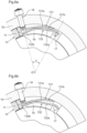
- the part of the elastic member 3 intended to cooperate with the push button 6 of the watch can be offset by an angle ⁇ with center O relative to the part of the elastic member 3 intended to cooperate with the control member 7 of the movement of this watch to trigger a predefined action, as illustrated in Figures 8a and 8b .
- the angle ⁇ is approximately 45°.
- the rigid part 3a of the casing circle 1 is bent and extends over an angle ⁇ with center O of approximately 75°. It is connected to the body 2 by means of a flexible guide member with circular necks constituting the elastic part 3b.
- the two parts of the elastic member 3 intended to cooperate respectively with the push button 6 and with the control member 7 of the movement are typically located in the rigid part 3a.
- the hollow of the bend of the rigid part 3a receives the part of the control member 7 of the movement with which it cooperates.
- the Figure 8a illustrates such a casing circle 1 at rest, that is to say when the push button 6 is not actuated, the elastic member 3 being in its rest position and the control member 7 being in a first position.
- figure 8b illustrates the same casing circle 1 when the push button 6 is actuated, the elastic part 3b of the elastic member 3 being deformed and the control member 7 being in a second position.
- a casing circle 10 for a wristwatch comprises an annular body 11 with center O and rigid as well as a first 131 and a second 132 elastic members forming with said body 11 a single-piece assembly.
- Each of said elastic members 131, 132 comprises a rigid part 131a, 132a movable relative to the body 11, and an elastic part 131b, 132b connecting the latter to the body 11.
- the rigid part 131a of the casing circle 10 is connected to the body 11 by means of an elastic part 131b consisting of a flexible guide member with circular necks.
- the rigid part 132a of the casing circle 10 is connected to the body 11 by means of an elastic part 132b consisting of a flexible guide member with circular necks.
- FIGS. 9a and 9b illustrate the casing ring 10 mounted in a watch. As for the first embodiment of the invention, it is arranged around the movement of this watch and inside its caseband 15.
- the first elastic member 131 cooperates, typically directly, on the one hand with a push button 16 of the watch, said button 16 passing through the caseband 15 and thus being partly outside the case of this watch as in the embodiment illustrated in the Figures 4 and 5 , and on the other hand with the second elastic member 132.
- the second elastic member 132 cooperates, typically directly, on the one hand with the first elastic member 131 and on the other hand with a movement control member 17 such as a control lever of which only a part is visible to the eye.
- Figures 9a and 9b .
- the first and second elastic members are arranged in series, that is to say arranged so that the actuation of said first elastic member 131 from outside the box actuates said control member 17 via said second elastic member 132.
- the rigid part 131a is moved towards the interior of the body 11 by deformation of the flexible guide member with circular necks 131b and acts in turn, by means of its side oriented towards the interior of the body 11, on the rigid part 132a of the second elastic member 132.
- the rigid part 132a is thus moved towards the interior of the body 11 by deformation of the flexible guide member with circular necks 132b and acts in turn on the control member 17 to trigger a predefined action.
- the part of the control member 17 intended to cooperate with the rigid part 132a is offset by an angle ⁇ of center O of approximately 45° relative to the axis of movement of the push button 16.
- the rigid part 131a of the casing circle 10 extends over a center angle O of approximately 35° and the rigid part 132a of the casing circle 10 extends over a center angle O of approximately 50°, these angles intersecting.
- the casing circle 10 is designed so that the rigid parts 131a, 132a of its elastic members 131, 132 are able to move with an amplitude sufficient to actuate the control member 17. This amplitude depends essentially on the deformation properties of the elastic parts 131b, 132b.
- the button 16 is typically a start/stop pushbutton or a reset pushbutton for a chronograph mechanism and the control member is typically a control lever 17 of a chronograph.
- the control member is typically a control lever 17 of a chronograph.
- the body 11 is a closed ring of width “L”. Like the body 2 of the casing circle 1 according to the embodiment illustrated in the Figures 4 and 5 , the body 11 will typically be able to carry its inner edge of the tabs to fix the casing circle 10 relative to the plate of the movement.
- the body 11 also comprises a recess 19 on its upper part in which the elastic members 131, 132 extend in part.
- the elastic members 131, 132 are located mainly above the body 11. They are intended to move in a plane parallel to that in which the body 11 extends, that is to say in a plane parallel to the plate of the movement. The upper part of the recess 19 participates in guiding them in this plane.
- each elastic member 131, 132 moves substantially along an arc of a circle relative to the body 11, the center of this arc of a circle corresponding, for each elastic member, to the pivot center of its flexible guide member with circular necks 131b, 132b.
- the nesting circle 10 illustrated in Figures 9a and 9b comprises two elastic members 131, 132 arranged in series, each of said elastic members comprising a rigid part 131a, 132a in the form of a slightly curved rigid arm and an elastic part 131b, 132 taking the form of a flexible guide member with circular necks.
- the casing circle 10 according to the second embodiment which is an embodiment of the invention, could comprise several series of at least two elastic members.
- Each series of elastic members of the casing circle 10 could comprise more than two elastic members, the said elastic member(s) of the series forming in any case with the body a single-piece assembly.
- each of the elastic members 131, 132 of the casing circle 10 can be connected to the body 11 by a single elastic part 131b, 132b, as in the case illustrated in Figures 9a and 9b , or by several elastic parts, typically two.
- the elastic members of the casing circle 10 may not include a rigid part 131a, 132a. They may then be simple elastic arms.
- Each of the elastic parts 131b, 132b can also take various shapes, other than that of a circular neck. More generally, the shape of the elastic members 131, 132 can vary infinitely as long as their functions are ensured.
- serial arrangement of several elastic members according to the second embodiment which is an embodiment of the invention, as in the case illustrated in Figures 9a and 9b , is particularly suitable for a casing ring intended to be used in a timepiece in which the push button must, typically for reasons of space, be offset by an angle ⁇ of center O relative to the movement control member.
- Such an arrangement remains possible, however, for use in all kinds of timepieces.
- each of the push buttons 6, 16 could be replaced by any other suitable actuator.
- the casing ring according to the invention is typically made of a non-magnetic copper alloy, such as brass, a copper-beryllium alloy or an alloy of copper, nickel and zinc possibly comprising lead known as nickel silver.
- the casing ring is rhodium-plated. It is typically made by mechanical machining, for example by chip removal, by electroerosion or by means of a laser.
- a casing ring for a timepiece comprising a body, at least one first elastic member as described in the first embodiment not falling within the scope of the invention and at least one series of at least two elastic members as described in the second embodiment, which is an embodiment of the invention, said first elastic member and said series of elastic members being arranged to cooperate respectively with first and second actuators intended to be actuated from outside the case of said timepiece to actuate respectively first and second control members of the movement of said timepiece, the body, the first elastic member and the series of at least two elastic members forming a single-piece assembly.
- the casing ring according to the invention can take various shapes, it is typically of the same shape as the watch case of the timepiece in which it is intended to be inserted, typically round as in the examples illustrated in the figures, or else oval, square, rectangular or polygonal for example. In these cases, it is intended to completely surround the movement of said timepiece. In variants, the casing ring according to the invention can also be intended to only partially surround the movement of said timepiece. It can thus be of a shape corresponding to only a portion of the aforementioned shapes, for example in an arc of a circle. It is typically the body of the casing ring which takes this shape.
- the casing circle according to the invention and in particular the fact that its body forms with its elastic members a single-piece assembly, has several advantages.
- each of its elastic members generates a restoring force, which can be used to return the push buttons to position after they have been actuated.
- the spring traditionally present in the push button such as button 106 illustrated in the figure 2 can be deleted.
- the restoring force of each of the elastic members is also easily adjustable, which makes it possible to simply manage the pressure required by the user to actuate a movement control member, this pressure having to be both sufficient to avoid its involuntary actuation but also limited for the comfort of the user.
- the adjustment of this force is typically done by playing on the thickness of the elastic members, on their length and/or on the material used for the production of the casing circle.
- the casing circle according to the invention also has the advantage of angularly offsetting the actuator accessible from the outside of the watch case relative to the control member that it must actuate in order to adapt to the possible size of the watch movement with which it interacts.
Landscapes
- Physics & Mathematics (AREA)
- General Physics & Mathematics (AREA)
- Electric Clocks (AREA)
Description
- La présente invention concerne un cercle d'emboîtage pour pièce d'horlogerie, ladite pièce d'horlogerie comprenant un mouvement et une boîte, ledit cercle d'emboîtage comprenant un corps destiné à entourer au moins partiellement le mouvement et au moins un organe d'actionnement destiné à être actionné depuis l'extérieur de la boîte pour actionner un organe de commande du mouvement.
- Par définition, le cercle d'emboîtage est une bague qui entoure au moins partiellement le mouvement. Il sert à combler l'espace entre le mouvement et la boîte.
- Dans les mouvements horlogers comprenant des complications, par exemple comprenant un mécanisme de chronographe, un mécanisme permettant l'affichage des phases de lune ou du quantième (annuel ou perpétuel), dans lesquels un ou plusieurs boutons actionnables depuis l'extérieur de la boîte de montre doivent actionner une fonction du mouvement, le cercle d'emboîtage porte typiquement des bascules.
- La montre Chrono Dame 7150 de chez Patek Philippe comprend un cercle d'emboîtage 100, typiquement en laiton rhodié, tel que représenté aux
figures 1 et 2 . Ce cercle d'emboîtage 100 comprend un corps annulaire rigide 101 et deux perçages 102 dans chacun desquels est chassé un tube 103 servant d'axe de rotation et de filetage pour une vis 104, une bascule 105 en acier trempé est montée sur ce tube et retenue par ladite vis 104. La bascule 105 est destinée à être actionnée par un bouton poussoir 106, cet actionneur 106 traversant la carrure 107 de la boîte de montre, comme illustré à lafigure 2 . Cette bascule 105 est un intermédiaire entre le bouton poussoir 106 et un organe de commande 108 du mouvement à actionner. - Traditionnellement, chacun des boutons poussoirs 106 illustrés à la
figure 2 intègre un ressort qui se contraint lorsque le bouton 106 associé est enfoncé de manière à pouvoir le repositionner après son actionnement. - Une difficulté technique principale dans la conception de telles structures réside dans le fait qu'elles comprennent de nombreuses pièces et peuvent conduire à la génération de particules de rhodiage qui polluent le mouvement lors du chassage des tubes 103 et/ou du vissage des bascules 105 dans le corps 101.
- Dans certaines pièces d'horlogerie, il arrive que l'agencement du mouvement rende difficile l'utilisation de moyens de commande tels que ceux illustrés aux
figures 1 et 2 . En effet, pour des raisons d'encombrement, il peut être préférable que l'actionneur accessible depuis l'extérieur de la boîte de montre soit décalé angulairement par rapport au moyen de commande qu'il doit actionner. - La montre « 5905P - complications » à remontage automatique de chez Patek Philippe comprend un cercle d'emboîtage 200 tel qu'illustré à la
figure 3 . - Le cercle d'emboîtage 200 comprend un corps annulaire rigide 201 et deux perçages dans chacun desquels est chassé un tube servant d'axe de rotation et de filetage pour une vis 204a, 204b. Des bascules 205a, 205b en acier trempé sont montées libres en rotation sur ces tubes et retenues par lesdites vis 204a, 204b. La bascule 205a est destinée à être actionnée par un bouton poussoir 206, traversant la carrure 207 de la boîte de montre.
- Chacune des deux bascules 205a, 205b comprend un premier bras, respectivement 2051a, 2051b et un second bras, respectivement 2052a, 2052b.
- Le premier bras 2051a de la première bascule 205a est destiné à coopérer avec le bouton poussoir 206 et le second bras 2052a de la première bascule est destiné à coopérer avec le premier bras 2051b de la seconde bascule 205b. Enfin, le second bras 2052b de la seconde bascule 205b est destiné à coopérer avec un organe de commande 208 du mouvement qu'il pourra actionner pour déclencher une action prédéfinie. On dit que les première 205a et seconde 205b bascules sont agencées en série.
- Le corps 201 porte un ressort 202 agencé pour exercer sur le second bras 2052b de la seconde bascule 205b une force l'éloignant de l'organe de commande 208 en tendant à faire pivoter cette dernière dans le sens antihoraire autour de sa vis 204b. Ainsi, en l'absence d'une action de l'utilisateur sur le poussoir 206, la seconde bascule 205b maintient le premier bras 2051a de la première bascule 205a en appui contre une goupille 209.
- Lorsque l'utilisateur veut déclencher l'action particulière commandée par l'organe de commande 208, il appuie sur le bouton poussoir 206 ce qui entraîne successivement la rotation dans le sens antihoraire de la première bascule 205a et la rotation dans le sens horaire de la seconde bascule 205b. La force exercée par l'utilisateur sur le poussoir 206 doit être suffisante pour vaincre celle exercée par le ressort 202 de manière à ce que le second bras 2052b de la seconde bascule 205b puisse déplacer l'organe de commande 208 en le poussant vers le centre du mouvement.
- Un tel cercle d'emboîtage 200 présente l'avantage de décaler angulairement l'actionneur 206 accessible depuis l'extérieur de la boîte de montre par rapport au moyen de commande 208 qu'il doit actionner pour s'adapter à l'encombrement éventuel du mouvement horloger avec lequel il interagit. Cependant, il comprend les mêmes inconvénients que ceux décrits précédemment pour le cercle d'emboîtage 100, à savoir un nombre de pièces important et le risque de générer des particules, typiquement de rhodiage, polluant le mouvement lors du montage des bascules 205a, 205b sur le corps 201.
- Le document
FR 2341154 - Un but de la présente invention est de pallier au moins en partie les inconvénients précités.
- L'invention propose à cette fin un cercle d'emboîtage pour pièce d'horlogerie selon la revendication 1. L'invention concerne également une pièce d'horlogerie telle qu'une montre-bracelet, une montre de poche, une pendule ou une pendulette comprenant un tel cercle d'emboîtage.
- D'autres caractéristiques et avantages de la présente invention apparaîtront à la lecture de la description détaillée suivante faite en référence aux dessins annexés dans lesquels :
- la
figure 1 représente, en perspective et en vue de dessus, un cercle d'emboîtage selon l'art antérieur ; - la
figure 2 représente, en coupe longitudinale et en vue de dessus, une partie d'une montre comprenant le cercle d'emboîtage illustré à lafigure 1 ; - la
figure 3 illustre, en coupe longitudinale et en vue de dessus, une partie d'une montre comprenant un autre cercle d'emboîtage selon l'art antérieur ; - la
figure 4 représente, en perspective, un cercle d'emboîtage selon un premier mode de réalisation ne relevant pas de l'invention mais décrit à titre illustratif ; - la
figure 5 illustre, en coupe longitudinale en vue de dessus, une partie d'une montre bracelet comprenant le cercle d'emboîtage illustré à lafigure 4 ; - la
figure 6 illustre, en coupe longitudinale en vue de dessus, une partie d'une montre comprenant une variante du cercle d'emboîtage représenté à lafigure 4 ; - la
figure 7 illustre, en coupe longitudinale en vue de dessus, une partie d'une montre comprenant une autre variante du cercle d'emboîtage représenté à lafigure 4 ; - les
figures 8a et 8b illustrent, en coupe longitudinale en vue de dessus, une partie d'une montre comprenant encore une autre variante du cercle d'emboîtage représenté à lafigure 4 ; - les
figures 9a et 9b illustrent, en coupe longitudinale en vue de dessus, une partie d'une montre comprenant un cercle d'emboîtage selon un second mode de réalisation, qui est un mode de réalisation de l'invention. - Les modes de réalisations suivants illustrés aux
figures 4 à 8b ne relèvent pas de l'invention et ne sont décrits ici qu'à titre illustratif. - En référence aux
figures 4 et 5 , un cercle d'emboîtage 1 pour une montre bracelet selon un premier mode de réalisation ne relevant pas de l'invention comprend un corps 2 annulaire de centre O et rigide et deux organes élastiques 3 formant avec ledit corps 2 un ensemble monobloc. Chacun desdits organes élastiques 3 comprend une partie rigide 3a, mobile par rapport au corps 2, et une partie élastique 3b reliant cette dernière au corps 2. La partie élastique prend ici la forme d'une lame élastique 3b et définit avec le corps 2 une interface de liaison 4 correspondant à l'interface entre le corps rigide 2 et la lame élastique 3b. - Dans l'exemple illustré aux
figures 4 et 5 , les deux organes élastiques 3 sont identiques. - La
figure 5 illustre le cercle d'emboîtage 1 monté dans une montre. Il est agencé autour du mouvement de cette montre et à l'intérieur de sa carrure 5. - La partie rigide 3a de chacun des organes élastiques 3 coopère, typiquement directement, d'une part avec un bouton poussoir 6 de la montre, ledit bouton poussoir 6 traversant la carrure 5 et étant en partie à l'extérieur de la boîte de cette montre, et d'autre part avec un organe de commande du mouvement tel qu'un levier de commande 7 dont seule une partie est visible à la
figure 5 . - Le côté de la partie rigide 3a de l'organe élastique 3 orienté vers l'extérieur du corps 2 coopère, typiquement directement, avec le bouton poussoir 6.
- Sous l'effet d'une pression exercée par le porteur de la montre illustrée à la
figure 5 sur ce bouton poussoir 6, la partie rigide 3a est déplacée vers l'intérieur du corps 2 et donc vers le mouvement et agit à son tour, par le biais de son côté orienté vers l'intérieur du corps 2, sur l'organe de commande 7 pour déclencher une action prédéfinie. Ce mouvement est rendu possible par la déformation élastique de la lame élastique 3b. - Dans l'exemple illustré à la
figure 5 , la partie de l'organe de commande 7 destinée à coopérer avec la partie rigide 3a se situe sur l'axe de déplacement du bouton poussoir 6, le bouton poussoir 6 et l'organe de commande 7 qu'il doit actionner se situent sur un même rayon du corps 2. - Le cercle d'emboîtage 1 est conçu de sorte que la partie rigide 3a de chacun de ses organes élastiques 3 soit apte à se déplacer avec une amplitude suffisante pour actionner l'organe de commande 7. Cette amplitude dépend essentiellement des propriétés de déformation de la partie élastique 3b associée.
- La partie rigide 3a forme une protubérance par rapport au reste de l'organe élastique 3. Cette forme élargie de la partie rigide 3a n'est pas indispensable mais elle présente l'avantage de la rendre proche des deux éléments avec lesquels elle coopère en fonctionnement, à savoir le bouton poussoir 6 et l'organe de commande 7. Ainsi, le bouton poussoir 6 n'aura à effectuer qu'un faible déplacement pour déplacer la partie rigide 3a qui n'aura ensuite à effectuer qu'un faible déplacement pour actionner l'organe de commande 7.
- Le bouton poussoir 6 est typiquement un poussoir de départ/arrêt ou un poussoir de remise à zéro pour un mécanisme de chronographe et l'organe de commande est typiquement un levier de commande 7 d'un chronographe. Dans ce cas, lorsque l'utilisateur appuie sur le bouton poussoir 6, il vient, par l'intermédiaire de l'organe élastique 3, actionner le levier de commande de chronographe 7 et, selon le cas, démarrer, stopper ou remettre à zéro le chronographe du mouvement.
- Dans l'exemple illustré aux
figures 4 et 5 , le corps 2 est un anneau fermé de largeur « L ». Il porte sur sa tranche intérieure des languettes 8, dont certaines sont percées, qui permettent de fixer le cercle d'emboîtage 1 par rapport à la platine du mouvement. - Le corps 2 comprend également des évidements 9 sur sa partie supérieure dans lesquels s'étendent les organes élastiques 3.
- En vue de dessus, lorsqu'ils sont au repos c'est-à-dire lorsqu'aucune force extérieure ne s'exerce sur eux, les organes élastiques 3 se situent majoritairement au-dessus du corps 2. Ils sont destinés à se déplacer dans un plan parallèle à celui dans lequel s'étend le corps 2, c'est-à-dire dans un plan parallèle à la platine du mouvement. La partie supérieure de chacun desdits évidements 9 participe à les guider dans ce plan.
- De par l'unique interface de liaison 4 de chaque organe d'actionnement 3 avec le corps 2, la partie rigide 3a de chaque organe élastique 3 se déplace sensiblement suivant un arc de cercle par rapport au corps 2, le centre de cet arc de cercle correspondant au centre de ladite interface de liaison 4.
- Le cercle d'emboîtage 1 illustré aux
figures 4 et 5 comprend deux organes élastiques 3 identiques, chacun d'eux comprenant une partie rigide 3a et une lame élastique 3b courbée, sensiblement en arc de cercle, reliant ladite partie rigide 3a au corps 2. - Dans des variantes, le cercle d'emboîtage 1 selon le premier mode de réalisation ne relevant pas de l'invention pourrait comprendre un seul organe élastique 3 ou plus de deux organes élastiques 3, par exemple trois ou quatre, le ou lesdits organes élastiques formant quoi qu'il en soit avec le corps 2 un ensemble monobloc.
- Dans le cas où le cercle d'emboîtage 1 comprend au moins deux organes élastiques 3, ceux-ci peuvent être identiques, comme dans l'exemple illustré aux
figures 4 à 7 , ou être différents ou en partie différents les uns des autres. - Quelle que soit la variante envisagée, chacun des organes élastiques 3 du cercle d'emboîtage 1 peut être relié au corps 2 par une seule partie élastique 3b, comme dans les cas illustrés aux
figures 4 à 6 , ou par plusieurs parties élastiques, par exemple par deux lames élastiques 3b, 3c comme dans le cas illustré à lafigure 7 . Dans ce cas particulier, chaque organe élastiques 3 comprend deux bras élastiques 3b, 3c identiques et agencés de part et d'autre d'une partie rigide 3a. Ceux-ci sont agencés pour que la partie rigide 3a soit apte à se déplacer selon une trajectoire linéaire par rapport au corps 2 ; ils sont diamétralement opposés par rapport à cette partie rigide 3a. La trajectoire linéaire qu'ils suivent s'étend radialement par rapport au cercle défini par le corps annulaire 2. Une telle trajectoire présente l'avantage de limiter à la fois les frottements entre le bouton poussoir 6 et la partie de l'organe élastique 3 avec laquelle il coopère lors de son actionnement et les frottements entre l'organe de commande 7 et la partie de l'organe élastique 3 avec laquelle il coopère lors de son actionnement. - Chacun des organes élastiques 3 du cercle d'emboîtage 1 peut ne pas comprendre de partie rigide 3a. Un tel organe élastique 3 comprend uniquement une partie élastique, typiquement un simple bras ou une simple lame élastique destiné(e) à coopérer d'une part avec le bouton poussoir 6 et d'autre part avec l'organe de commande 7 du mouvement, par une ou plusieurs parties.
- De plus, chacune des parties élastiques 3b du cercle d'emboîtage 1 peut prendre diverses formes, par exemple courbée, comme illustré aux
figures 4 et 5 , droite, comme illustré à lafigure 6 , ou encore sinueuse comme illustré à lafigure 7 . Plus généralement, la forme des organes élastique 3 peut varier à l'infini pour autant que leurs fonctions soient assurées. - En outre, contrairement aux exemples illustrés aux
figures 4 à 7 , la partie de l'organe élastique 3 destinée à coopérer avec le bouton poussoir 6 de la montre peut être décalée d'un angle α de centre O par rapport à la partie de l'organe élastique 3 destinée à coopérer avec l'organe de commande 7 du mouvement de cette montre pour déclencher une action prédéfinie, comme illustré auxfigures 8a et 8b . Dans la variante illustrée auxfigures 8a et 8b , l'angle α est d'environ 45°. Afin de permettre un tel décalage angulaire, la partie rigide 3a du cercle d'emboîtage 1 est coudée et s'étend sur un angle β de centre O d'environ 75°. Elle est reliée au corps 2 par l'intermédiaire d'un organe de guidage flexible à cols circulaires constituant la partie élastique 3b. Les deux parties de l'organe élastique 3 destinées à coopérer respectivement avec le bouton poussoir 6 et avec l'organe de commande 7 du mouvement se situent typiquement dans la partie rigide 3a. Le creux du coude de la partie rigide 3a reçoit la partie de l'organe de commande 7 du mouvement avec laquelle il coopère. Lafigure 8a illustre un tel cercle d'emboîtage 1 au repos, c'est-à-dire lorsque le bouton poussoir 6 n'est pas actionné, l'organe élastique 3 se trouvant dans sa position de repos et l'organe de commande 7 étant dans une première position. Lafigure 8b illustre quant à elle le même cercle d'emboîtage 1 lorsque le bouton poussoir 6 est actionné, la partie élastique 3b de l'organe élastique 3 étant déformée et l'organe de commande 7 se trouvant dans une seconde position. - En référence aux
figures 9a et 9b , un cercle d'emboîtage 10 pour montre bracelet selon un second mode de réalisation, qui est un mode de réalisation de l'invention, comprend un corps 11 annulaire de centre O et rigide ainsi qu'un premier 131 et un second 132 organes élastiques formant avec ledit corps 11 un ensemble monobloc. - Chacun desdits organes élastiques 131, 132 comprend une partie rigide 131a, 132a mobile par rapport au corps 11, et une partie élastique 131b, 132b reliant cette dernière au corps 11.
- La partie rigide 131a du cercle d'emboîtage 10 est reliée au corps 11 par l'intermédiaire d'une partie élastique 131b constituée d'un organe de guidage flexible à cols circulaires. De même, la partie rigide 132a du cercle d'emboîtage 10 est reliée au corps 11 par l'intermédiaire d'une partie élastique 132b constituée d'un organe de guidage flexible à cols circulaires.
- Les
figures 9a et 9b illustrent le cercle d'emboîtage 10 monté dans une montre. Comme pour le premier mode de réalisation de l'invention, il est agencé autour du mouvement de cette montre et à l'intérieur de sa carrure 15. - Le premier organe élastique 131 coopère, typiquement directement, d'une part avec un bouton poussoir 16 de la montre, ledit bouton 16 traversant la carrure 15 et étant ainsi en partie à l'extérieur de la boîte de cette montre comme dans le mode de réalisation illustré dans les
figures 4 et 5 , et d'autre part avec le second organe élastique 132. Le second organe élastique 132 coopère quant à lui, typiquement directement, d'une part avec le premier organe élastique 131 et d'autre part avec un organe de commande du mouvement 17 tel qu'un levier de commande dont seule une partie est visible auxfigures 9a et 9b . En d'autres termes, les premier et second organes élastiques sont agencés en série, c'est-à-dire agencés de sorte que l'actionnement dudit premier organe élastique 131 depuis l'extérieur de la boîte actionne ledit organe de commande 17 par l'intermédiaire dudit second organe élastique 132. - Sous l'effet d'une pression exercée par le porteur de la montre illustrée aux
figures 9a et 9b sur le bouton poussoir 16, la partie rigide 131a est déplacée vers l'intérieur du corps 11 par déformation de l'organe de guidage flexible à cols circulaires 131b et agit à son tour, par le biais de son côté orienté vers l'intérieur du corps 11, sur la partie rigide 132a du second organe élastique 132. La partie rigide 132a est ainsi déplacée vers l'intérieur du corps 11 par déformation de l'organe de guidage flexible à cols circulaires 132b et agit à son tour sur l'organe de commande 17 pour déclencher une action prédéfinie. - Dans l'exemple illustré, la partie de l'organe de commande 17 destinée à coopérer avec la partie rigide 132a est décalée d'un angle α de centre O d'environ 45° par rapport à l'axe de déplacement du bouton poussoir 16. Afin de permettre un tel décalage angulaire, la partie rigide 131a du cercle d'emboîtage 10 s'étend sur un angle de centre O d'environ 35° et la partie rigide 132a du cercle d'emboîtage 10 s'étend sur un angle de centre O d'environ 50°, ces angles se recoupant.
- Le cercle d'emboîtage 10 est conçu de sorte que les parties rigides 131a, 132a de ses organes élastiques 131, 132 soient aptes à se déplacer avec une amplitude suffisante pour actionner l'organe de commande 17. Cette amplitude dépend essentiellement des propriétés de déformation des parties élastiques 131b, 132b.
- Comme dans le mode de réalisation illustré dans les
figures 4 et 5 , le bouton 16 est typiquement un poussoir de départ/arrêt ou un poussoir de remise à zéro pour un mécanisme de chronographe et l'organe de commande est typiquement un levier de commande 17 d'un chronographe. Dans ce cas, lorsque l'utilisateur appuie sur le bouton 16, il vient, par l'intermédiaire des organes élastiques 131, 132, actionner le levier de commande de chronographe 17 et, selon le cas, démarrer, stopper ou remettre à zéro le chronographe du mouvement. - Dans l'exemple illustré aux
figures 9a et 9b , le corps 11 est un anneau fermé de largeur « L ». Comme le corps 2 du cercle d'emboîtage 1 selon le mode de réalisation illustré dans lesfigures 4 et 5 , le corps 11 pourra typiquement porter sa tranche intérieure des languettes pour fixer le cercle d'emboîtage 10 par rapport à la platine du mouvement. - Le corps 11 comprend également un évidement 19 sur sa partie supérieure dans lequel s'étendent en partie les organes élastiques 131, 132.
- En vue de dessus, lorsqu'ils sont au repos c'est-à-dire lorsqu'aucune force extérieure ne s'exerce sur eux, les organes élastiques 131, 132 se situent majoritairement au-dessus du corps 11. Ils sont destinés à se déplacer dans un plan parallèle à celui dans lequel s'étend le corps 11, c'est-à-dire dans un plan parallèle à la platine du mouvement. La partie supérieure de l'évidement 19 participe à les guider dans ce plan.
- La partie rigide 131a, 132a de chaque organe élastique 131, 132 se déplace sensiblement suivant un arc de cercle par rapport au corps 11, le centre de cet arc de cercle correspondant, pour chaque organe élastique au centre de pivotement de son organe de guidage flexible à cols circulaires 131b, 132b
- Le cercle d'emboîtage 10 illustré aux
figures 9a et 9b comprend deux organes élastiques 131, 132 agencés en série, chacun desdits organes élastiques comprenant une partie rigide 131a, 132a en forme de bras rigide légèrement courbé et un une partie élastique 131b, 132 prenant la forme d'un organe de guidage flexible à cols circulaires. - Dans des variantes, le cercle d'emboîtage 10 selon le second mode de réalisation, qui est un mode de réalisation de l'invention, pourrait comprendre plusieurs séries d'au moins deux organes élastiques.
- Chaque série d'organes élastiques du cercle d'emboîtage 10 pourrait comprendre plus de deux organes élastiques, le ou lesdits organes élastiques de la série formant quoi qu'il en soit avec le corps un ensemble monobloc.
- Quelle que soit la variante envisagée, chacun des organes élastiques 131, 132 du cercle d'emboîtage 10 peut être relié au corps 11 par une seule partie élastique 131b, 132b, comme dans le cas illustré aux
figures 9a et 9b , ou par plusieurs parties élastiques, typiquement deux. - Quelle que soit la variante envisagée, les organes élastiques du cercle d'emboîtage 10 peuvent ne pas comprendre de partie rigide 131a, 132a. Il peut alors s'agir de simples bras élastiques.
- Chacune des parties élastiques 131b, 132b peut également prendre diverses formes, autre que celle d'un col circulaire. Plus généralement, la forme des organes élastiques 131, 132 peut varier à l'infini pour autant que leurs fonctions soient assurées.
- L'agencement en série de plusieurs organes élastiques conformément au second mode de réalisation, qui est un mode de réalisation de l'invention, comme dans le cas illustré aux
figures 9a et 9b , est particulièrement adapté pour un cercle d'emboîtage destiné à être utilisé dans une pièce d'horlogerie dans laquelle le bouton poussoir doit, typiquement pour des raisons d'encombrement, être décalé d'un angle α de centre O par rapport à l'organe de commande du mouvement. Un tel agencement reste cependant possible pour une utilisation dans toutes sortes de pièces d'horlogerie. - Quel que soit le mode de réalisation de la présente invention, chacun des boutons poussoirs 6, 16 pourrait être remplacé par tout autre actionneur convenable.
- Le cercle d'emboîtage selon l'invention est typiquement réalisé dans un alliage cuivreux, amagnétique, tel que le laiton, un alliage cuivre-béryllium ou encore un alliage de cuivre, nickel et zinc comprenant éventuellement du plomb connu sous le nom de maillechort. Avantageusement, le cercle d'emboîtage est rhodié. Il est typiquement réalisé par un usinage mécanique, par exemple par enlèvement de copeaux, par électroérosion ou au moyen d'un laser.
- Il apparaîtra clairement à l'homme du métier que la présente invention n'est en aucun cas limitée aux modes de réalisation présentés ci-dessus et illustrés dans les figures, tout en restant définie par le jeu de revendications annexé.
- Il est par exemple très bien envisageable de réaliser un cercle d'emboîtage combinant les premier et second modes de réalisation décrits ci-dessus, par exemple un cercle d'emboîtage pour pièce d'horlogerie comprenant un corps, au moins un premier organe élastique tel que décrit dans le premier mode de réalisation ne relevant pas de l'invention et au moins une série d'au moins deux organes élastiques tel que décrite dans le second mode de réalisation, qui est un mode de réalisation de l'invention, ledit premier organe élastique et ladite série d'organes élastiques étant agencés pour coopérer respectivement avec des premier et second actionneurs destinés à être actionnés depuis l'extérieur de la boîte de ladite pièce d'horlogerie pour actionner respectivement des premier et second organes de commande du mouvement de ladite pièce d'horlogerie, le corps, le premier organe élastique et la série d'au moins deux organes élastiques formant un ensemble monobloc.
- Le cercle d'emboîtage selon l'invention peut prendre diverses formes, il est typiquement de la même forme que la boîte de montre de la pièce d'horlogerie dans laquelle il est destiné à être inséré, typiquement rond comme dans les exemples illustrés aux figures, ou bien ovale, carré, rectangulaire ou polygonal par exemple. Dans ces cas, il est destiné à entourer complètement le mouvement de ladite pièce d'horlogerie. Dans des variantes, le cercle d'emboîtage selon l'invention peut également être destiné à n'entourer que partiellement le mouvement de ladite pièce d'horlogerie. Il peut ainsi être d'une forme correspondant à seulement une portion des formes précitées, par exemple en arc de cercle. C'est typiquement le corps du cercle d'emboîtage qui prend cette forme.
- Quel que soit le mode de réalisation de l'invention, le cercle d'emboîtage selon l'invention, et en particulier le fait que son corps forme avec ses organes élastiques un ensemble monobloc, présente plusieurs avantages.
- Cela limite le nombre d'éléments et facilite donc le montage de la pièce d'horlogerie. De plus, éliminer les vis et le chassage d'un pas de vis ou de tout autre goupille de montage pour l'assemblage de bascules telles que celles 105 illustrées à la
figure 1 évite également de former des particules, typiquement de rhodiage, susceptibles de gêner le mouvement. - L'absence de vis donne plus de liberté quant à la largeur « L » du cercle d'emboîtage qui n'est plus assujettie par les dimensions de vis.
- Un autre avantage du cercle d'emboîtage vient du fait que chacun de ses organes élastiques engendre une force de rappel, qui peut être utilisée pour le rappel en position des boutons poussoirs après leur actionnement. Ainsi, le ressort traditionnellement présent dans le bouton poussoir tel que le bouton 106 illustré à la
figure 2 peut être supprimé. - La force de rappel de chacun des organes élastiques est en outre facilement ajustable ce qui permet de gérer simplement la pression nécessaire à l'utilisateur pour actionner un organe de commande du mouvement, cette pression devant à la fois être suffisante pour éviter son actionnement involontaire mais également limitée pour le confort de l'utilisateur. L'ajustement de cette force se fait typiquement en jouant sur l'épaisseur des organes élastiques, sur leur longueur et/ou sur le matériau utilisé pour la réalisation du cercle d'emboîtage.
- Enfin, selon la variante mise en oeuvre, le cercle d'emboîtage selon l'invention présente également l'avantage de décaler angulairement l'actionneur accessible depuis l'extérieur de la boîte de montre par rapport à l'organe de commande qu'il doit actionner pour s'adapter à l'encombrement éventuel du mouvement horloger avec lequel il interagit.
Claims (12)
- Cercle d'emboîtage (1 ; 10) pour pièce d'horlogerie, ladite pièce d'horlogerie comprenant un mouvement et une boîte, ledit cercle d'emboîtage (1 ; 10) comprenant un corps (2 ; 11) destiné à entourer au moins partiellement le mouvement et au moins un organe d'actionnement (3 ; 131) destiné à être actionné depuis l'extérieur de la boîte pour actionner un organe de commande (7 ; 17) du mouvement, ledit organe d'actionnement (3 ; 131) étant élastique et formant avec ledit corps (2 ; 11) un ensemble monobloc, caractérisé en ce qu'il comprend au moins un autre organe élastique (132) agencé en série avec ledit organe d'actionnement (131) de sorte que l'actionnement dudit organe d'actionnement (131) depuis l'extérieur de la boîte actionne ledit organe de commande (17) par l'intermédiaire dudit autre organe élastique (132), ledit autre organe élastique (132) faisant partie de l'ensemble monobloc.
- Cercle d'emboîtage (1 ; 10) selon la revendication 1, caractérisé en ce que ledit organe d'actionnement (3 ; 131) comprend une partie rigide (3a ; 131a) mobile par rapport au corps (2 ; 11) et au moins une partie élastique (3b ; 131b) reliant ladite partie rigide (3a ; 131a) au corps (2 ; 11).
- Cercle d'emboîtage (1) selon la revendication 2, caractérisé en ce que ledit organe d'actionnement (3) comprend deux parties élastiques (3b, 3c) agencées de part et d'autre de ladite partie rigide (3a) de manière à la guider en translation par rapport au corps (2).
- Cercle d'emboîtage (1 ; 10) selon la revendication 2 ou 3, caractérisé en ce que ladite partie rigide (3a ; 131a) forme une protubérance par rapport à ladite ou auxdites partie(s) élastique(s) (3b ; 131b).
- Cercle d'emboîtage (10) selon l'une des revendications précédentes, caractérisé en ce que ledit autre organe élastique comprend également une partie rigide (132a) mobile par rapport au corps (11) et au moins une partie élastique (132b) reliant ladite partie rigide (131a) au corps (11).
- Cercle d'emboîtage (1 ; 10) selon l'une des revendications précédentes, caractérisé en ce que ledit ensemble monobloc est réalisé en un alliage cuivreux amagnétique, de préférence choisi parmi le laiton, un alliage cuivre-béryllium ou un alliage de cuivre, nickel et zinc comprenant éventuellement du plomb.
- Cercle d'emboîtage (1 ; 10) selon l'une des revendications précédentes, caractérisé en ce qu'il est de forme ronde, carrée, ovale, rectangulaire ou correspondant à une portion desdites formes, par exemple en arc de cercle.
- Pièce d'horlogerie telle qu'une montre-bracelet, une montre de poche, une pendule ou une pendulette comprenant un cercle d'emboîtage (1 ; 10) selon l'une des revendications 1 à 7.
- Pièce d'horlogerie selon la revendication 8, caractérisée en ce qu'elle comprend un actionneur (6 ; 16), au moins en partie à l'extérieur de la boîte, dont l'actionnement déforme élastiquement ledit organe d'actionnement (2 ; 131) de sorte que celui-actionne, directement ou indirectement par le biais dudit autre organe élastique (132), ledit organe de commande (17).
- Pièce d'horlogerie selon la revendication 9, caractérisée en ce que ledit actionneur (6 ; 16) et l'organe de commande sont décalés l'un par rapport à l'autre d'un angle α de centre O correspondant au centre du corps (2 ; 11), ledit angle α étant d'au moins 5°, de préférence d'au moins 10°, de préférence d'au moins 20°, de préférence d'au moins 30°, de préférence encore d'au moins 40°.
- Pièce d'horlogerie selon la revendication 9 ou 10, caractérisée en ce que ledit actionneur (6 ; 16) est un bouton poussoir traversant la carrure de la boîte.
- Pièce d'horlogerie selon l'une des revendications 8 à 10, caractérisée en ce que l'organe de commande (7 ; 17) est un levier de commande tel qu'un levier de commande de chronographe.
Priority Applications (1)
| Application Number | Priority Date | Filing Date | Title |
|---|---|---|---|
| EP19166736.9A EP3719582B1 (fr) | 2019-04-02 | 2019-04-02 | Cercle d'emboîtage pour piece d'horlogerie |
Applications Claiming Priority (1)
| Application Number | Priority Date | Filing Date | Title |
|---|---|---|---|
| EP19166736.9A EP3719582B1 (fr) | 2019-04-02 | 2019-04-02 | Cercle d'emboîtage pour piece d'horlogerie |
Publications (2)
| Publication Number | Publication Date |
|---|---|
| EP3719582A1 EP3719582A1 (fr) | 2020-10-07 |
| EP3719582B1 true EP3719582B1 (fr) | 2024-12-11 |
Family
ID=66091911
Family Applications (1)
| Application Number | Title | Priority Date | Filing Date |
|---|---|---|---|
| EP19166736.9A Active EP3719582B1 (fr) | 2019-04-02 | 2019-04-02 | Cercle d'emboîtage pour piece d'horlogerie |
Country Status (1)
| Country | Link |
|---|---|
| EP (1) | EP3719582B1 (fr) |
Citations (1)
| Publication number | Priority date | Publication date | Assignee | Title |
|---|---|---|---|---|
| FR2341154A1 (fr) * | 1976-02-12 | 1977-09-09 | Bulova Watch Co Inc | Anneau de montage pour mouvement d'horlogerie |
Family Cites Families (3)
| Publication number | Priority date | Publication date | Assignee | Title |
|---|---|---|---|---|
| FR2548797A1 (fr) * | 1983-07-05 | 1985-01-11 | Yema | Dispositif de commande et de reglage de positionnement d'une lunette de montre |
| EP1710635A1 (fr) * | 2005-04-04 | 2006-10-11 | Bruno Affolter S.A. | Dispositif de commande pour pièce d'horlogerie et montre munie d'un tel dispositif |
| EP1890202A1 (fr) * | 2006-08-17 | 2008-02-20 | The Swatch Group Research and Development Ltd. | Dispositif de commande pour pièce d'horlogerie |
-
2019
- 2019-04-02 EP EP19166736.9A patent/EP3719582B1/fr active Active
Patent Citations (1)
| Publication number | Priority date | Publication date | Assignee | Title |
|---|---|---|---|---|
| FR2341154A1 (fr) * | 1976-02-12 | 1977-09-09 | Bulova Watch Co Inc | Anneau de montage pour mouvement d'horlogerie |
Also Published As
| Publication number | Publication date |
|---|---|
| EP3719582A1 (fr) | 2020-10-07 |
Similar Documents
| Publication | Publication Date | Title |
|---|---|---|
| EP3559755B1 (fr) | Composant monolithique flexible pour pièce d'horlogerie | |
| EP2048548B1 (fr) | Mécanisme de sonnerie | |
| EP3206089A1 (fr) | Mécanisme résonateur d'horlogerie | |
| EP3457221A2 (fr) | Oscillateur horloger a pivot flexible | |
| EP2776894B1 (fr) | Mecanisme d'entrainement d'un indicateur | |
| EP2957964B1 (fr) | Dispositif d'embrayage basculant pour pièce d'horlogerie | |
| EP2766778B1 (fr) | Piece d'horlogerie | |
| EP3629102B1 (fr) | Mécanisme d'affichage à guichet unique | |
| EP3824354A1 (fr) | Mecanisme horloger a came | |
| EP3401740A1 (fr) | Composant horloger pour chassage sans bavure | |
| EP3719582B1 (fr) | Cercle d'emboîtage pour piece d'horlogerie | |
| EP2798414B1 (fr) | Ressort pour mouvement horloger | |
| WO2009141262A1 (fr) | Mecanisme de piece d'horlogerie et module comprenant un tel mecanisme | |
| EP4273635B1 (fr) | Mouvement d'horlogerie | |
| EP1801671A1 (fr) | Montre à calendrier pourvu de moyens de blocage | |
| EP3407142A1 (fr) | Mouvement horloger a fonction "stop second" | |
| CH719059B1 (fr) | Dispositif horloger comprenant un marteau comportant deux parties reliées entre elles par un organe de guidage flexible. | |
| EP3486735A1 (fr) | Mecanisme horloger de remise a zero de la seconde a came en colimacon | |
| EP1316863A1 (fr) | Pièce d'horlogerie à mouvement de forme muni d'un chronographe | |
| EP1475682B1 (fr) | Montre-chronographe à affichage instantané de fractions de seconde | |
| EP4425275B1 (fr) | Mecanisme horloger | |
| EP3907563A1 (fr) | Mécanisme horloger comprenant un organe pivot | |
| EP4425272B1 (fr) | Mecanisme horloger | |
| EP3714336B1 (fr) | Maintien d'un mobile portant un disque d'affichage | |
| EP1960843A2 (fr) | Mouvement horloger |
Legal Events
| Date | Code | Title | Description |
|---|---|---|---|
| PUAI | Public reference made under article 153(3) epc to a published international application that has entered the european phase |
Free format text: ORIGINAL CODE: 0009012 |
|
| STAA | Information on the status of an ep patent application or granted ep patent |
Free format text: STATUS: THE APPLICATION HAS BEEN PUBLISHED |
|
| AK | Designated contracting states |
Kind code of ref document: A1 Designated state(s): AL AT BE BG CH CY CZ DE DK EE ES FI FR GB GR HR HU IE IS IT LI LT LU LV MC MK MT NL NO PL PT RO RS SE SI SK SM TR |
|
| AX | Request for extension of the european patent |
Extension state: BA ME |
|
| STAA | Information on the status of an ep patent application or granted ep patent |
Free format text: STATUS: REQUEST FOR EXAMINATION WAS MADE |
|
| 17P | Request for examination filed |
Effective date: 20210311 |
|
| RBV | Designated contracting states (corrected) |
Designated state(s): AL AT BE BG CH CY CZ DE DK EE ES FI FR GB GR HR HU IE IS IT LI LT LU LV MC MK MT NL NO PL PT RO RS SE SI SK SM TR |
|
| REG | Reference to a national code |
Ref country code: DE Ref legal event code: R079 Free format text: PREVIOUS MAIN CLASS: G04B0003040000 Ref country code: DE Ref legal event code: R079 Ref document number: 602019063289 Country of ref document: DE Free format text: PREVIOUS MAIN CLASS: G04B0003040000 Ipc: G04B0029000000 |
|
| RIC1 | Information provided on ipc code assigned before grant |
Ipc: G04B 3/04 20060101AFI20220804BHEP |
|
| RIC1 | Information provided on ipc code assigned before grant |
Ipc: G04B 3/04 20060101ALI20220824BHEP Ipc: G04B 29/00 20060101AFI20220824BHEP |
|
| STAA | Information on the status of an ep patent application or granted ep patent |
Free format text: STATUS: EXAMINATION IS IN PROGRESS |
|
| 17Q | First examination report despatched |
Effective date: 20221108 |
|
| P01 | Opt-out of the competence of the unified patent court (upc) registered |
Effective date: 20230521 |
|
| GRAP | Despatch of communication of intention to grant a patent |
Free format text: ORIGINAL CODE: EPIDOSNIGR1 |
|
| STAA | Information on the status of an ep patent application or granted ep patent |
Free format text: STATUS: GRANT OF PATENT IS INTENDED |
|
| INTG | Intention to grant announced |
Effective date: 20240712 |
|
| GRAS | Grant fee paid |
Free format text: ORIGINAL CODE: EPIDOSNIGR3 |
|
| GRAA | (expected) grant |
Free format text: ORIGINAL CODE: 0009210 |
|
| STAA | Information on the status of an ep patent application or granted ep patent |
Free format text: STATUS: THE PATENT HAS BEEN GRANTED |
|
| AK | Designated contracting states |
Kind code of ref document: B1 Designated state(s): AL AT BE BG CH CY CZ DE DK EE ES FI FR GB GR HR HU IE IS IT LI LT LU LV MC MK MT NL NO PL PT RO RS SE SI SK SM TR |
|
| REG | Reference to a national code |
Ref country code: GB Ref legal event code: FG4D Free format text: NOT ENGLISH |
|
| REG | Reference to a national code |
Ref country code: CH Ref legal event code: EP |
|
| REG | Reference to a national code |
Ref country code: IE Ref legal event code: FG4D Free format text: LANGUAGE OF EP DOCUMENT: FRENCH |
|
| REG | Reference to a national code |
Ref country code: DE Ref legal event code: R096 Ref document number: 602019063289 Country of ref document: DE |
|
| REG | Reference to a national code |
Ref country code: LT Ref legal event code: MG9D |
|
| PG25 | Lapsed in a contracting state [announced via postgrant information from national office to epo] |
Ref country code: HR Free format text: LAPSE BECAUSE OF FAILURE TO SUBMIT A TRANSLATION OF THE DESCRIPTION OR TO PAY THE FEE WITHIN THE PRESCRIBED TIME-LIMIT Effective date: 20241211 |
|
| PG25 | Lapsed in a contracting state [announced via postgrant information from national office to epo] |
Ref country code: FI Free format text: LAPSE BECAUSE OF FAILURE TO SUBMIT A TRANSLATION OF THE DESCRIPTION OR TO PAY THE FEE WITHIN THE PRESCRIBED TIME-LIMIT Effective date: 20241211 |
|
| PG25 | Lapsed in a contracting state [announced via postgrant information from national office to epo] |
Ref country code: BG Free format text: LAPSE BECAUSE OF FAILURE TO SUBMIT A TRANSLATION OF THE DESCRIPTION OR TO PAY THE FEE WITHIN THE PRESCRIBED TIME-LIMIT Effective date: 20241211 |
|
| REG | Reference to a national code |
Ref country code: NL Ref legal event code: MP Effective date: 20241211 |
|
| PG25 | Lapsed in a contracting state [announced via postgrant information from national office to epo] |
Ref country code: ES Free format text: LAPSE BECAUSE OF FAILURE TO SUBMIT A TRANSLATION OF THE DESCRIPTION OR TO PAY THE FEE WITHIN THE PRESCRIBED TIME-LIMIT Effective date: 20241211 |
|
| PG25 | Lapsed in a contracting state [announced via postgrant information from national office to epo] |
Ref country code: NO Free format text: LAPSE BECAUSE OF FAILURE TO SUBMIT A TRANSLATION OF THE DESCRIPTION OR TO PAY THE FEE WITHIN THE PRESCRIBED TIME-LIMIT Effective date: 20250311 |
|
| PG25 | Lapsed in a contracting state [announced via postgrant information from national office to epo] |
Ref country code: LV Free format text: LAPSE BECAUSE OF FAILURE TO SUBMIT A TRANSLATION OF THE DESCRIPTION OR TO PAY THE FEE WITHIN THE PRESCRIBED TIME-LIMIT Effective date: 20241211 Ref country code: GR Free format text: LAPSE BECAUSE OF FAILURE TO SUBMIT A TRANSLATION OF THE DESCRIPTION OR TO PAY THE FEE WITHIN THE PRESCRIBED TIME-LIMIT Effective date: 20250312 |
|
| PG25 | Lapsed in a contracting state [announced via postgrant information from national office to epo] |
Ref country code: RS Free format text: LAPSE BECAUSE OF FAILURE TO SUBMIT A TRANSLATION OF THE DESCRIPTION OR TO PAY THE FEE WITHIN THE PRESCRIBED TIME-LIMIT Effective date: 20250311 |
|
| PG25 | Lapsed in a contracting state [announced via postgrant information from national office to epo] |
Ref country code: NL Free format text: LAPSE BECAUSE OF FAILURE TO SUBMIT A TRANSLATION OF THE DESCRIPTION OR TO PAY THE FEE WITHIN THE PRESCRIBED TIME-LIMIT Effective date: 20241211 |
|
| REG | Reference to a national code |
Ref country code: AT Ref legal event code: MK05 Ref document number: 1750880 Country of ref document: AT Kind code of ref document: T Effective date: 20241211 |
|
| PG25 | Lapsed in a contracting state [announced via postgrant information from national office to epo] |
Ref country code: SM Free format text: LAPSE BECAUSE OF FAILURE TO SUBMIT A TRANSLATION OF THE DESCRIPTION OR TO PAY THE FEE WITHIN THE PRESCRIBED TIME-LIMIT Effective date: 20241211 |
|
| PG25 | Lapsed in a contracting state [announced via postgrant information from national office to epo] |
Ref country code: PL Free format text: LAPSE BECAUSE OF FAILURE TO SUBMIT A TRANSLATION OF THE DESCRIPTION OR TO PAY THE FEE WITHIN THE PRESCRIBED TIME-LIMIT Effective date: 20241211 |
|
| PG25 | Lapsed in a contracting state [announced via postgrant information from national office to epo] |
Ref country code: IS Free format text: LAPSE BECAUSE OF FAILURE TO SUBMIT A TRANSLATION OF THE DESCRIPTION OR TO PAY THE FEE WITHIN THE PRESCRIBED TIME-LIMIT Effective date: 20250411 |
|
| PG25 | Lapsed in a contracting state [announced via postgrant information from national office to epo] |
Ref country code: PT Free format text: LAPSE BECAUSE OF FAILURE TO SUBMIT A TRANSLATION OF THE DESCRIPTION OR TO PAY THE FEE WITHIN THE PRESCRIBED TIME-LIMIT Effective date: 20250411 |
|
| PG25 | Lapsed in a contracting state [announced via postgrant information from national office to epo] |
Ref country code: EE Free format text: LAPSE BECAUSE OF FAILURE TO SUBMIT A TRANSLATION OF THE DESCRIPTION OR TO PAY THE FEE WITHIN THE PRESCRIBED TIME-LIMIT Effective date: 20241211 |
|
| PGFP | Annual fee paid to national office [announced via postgrant information from national office to epo] |
Ref country code: CH Payment date: 20250501 Year of fee payment: 7 |
|
| PG25 | Lapsed in a contracting state [announced via postgrant information from national office to epo] |
Ref country code: AT Free format text: LAPSE BECAUSE OF FAILURE TO SUBMIT A TRANSLATION OF THE DESCRIPTION OR TO PAY THE FEE WITHIN THE PRESCRIBED TIME-LIMIT Effective date: 20241211 Ref country code: RO Free format text: LAPSE BECAUSE OF FAILURE TO SUBMIT A TRANSLATION OF THE DESCRIPTION OR TO PAY THE FEE WITHIN THE PRESCRIBED TIME-LIMIT Effective date: 20241211 |
|
| PG25 | Lapsed in a contracting state [announced via postgrant information from national office to epo] |
Ref country code: SK Free format text: LAPSE BECAUSE OF FAILURE TO SUBMIT A TRANSLATION OF THE DESCRIPTION OR TO PAY THE FEE WITHIN THE PRESCRIBED TIME-LIMIT Effective date: 20241211 |
|
| PG25 | Lapsed in a contracting state [announced via postgrant information from national office to epo] |
Ref country code: CZ Free format text: LAPSE BECAUSE OF FAILURE TO SUBMIT A TRANSLATION OF THE DESCRIPTION OR TO PAY THE FEE WITHIN THE PRESCRIBED TIME-LIMIT Effective date: 20241211 |
|
| PG25 | Lapsed in a contracting state [announced via postgrant information from national office to epo] |
Ref country code: IT Free format text: LAPSE BECAUSE OF FAILURE TO SUBMIT A TRANSLATION OF THE DESCRIPTION OR TO PAY THE FEE WITHIN THE PRESCRIBED TIME-LIMIT Effective date: 20241211 |
|
| PG25 | Lapsed in a contracting state [announced via postgrant information from national office to epo] |
Ref country code: SE Free format text: LAPSE BECAUSE OF FAILURE TO SUBMIT A TRANSLATION OF THE DESCRIPTION OR TO PAY THE FEE WITHIN THE PRESCRIBED TIME-LIMIT Effective date: 20241211 |
|
| REG | Reference to a national code |
Ref country code: DE Ref legal event code: R097 Ref document number: 602019063289 Country of ref document: DE |
|
| PG25 | Lapsed in a contracting state [announced via postgrant information from national office to epo] |
Ref country code: DK Free format text: LAPSE BECAUSE OF FAILURE TO SUBMIT A TRANSLATION OF THE DESCRIPTION OR TO PAY THE FEE WITHIN THE PRESCRIBED TIME-LIMIT Effective date: 20241211 |
|
| PLBE | No opposition filed within time limit |
Free format text: ORIGINAL CODE: 0009261 |
|
| STAA | Information on the status of an ep patent application or granted ep patent |
Free format text: STATUS: NO OPPOSITION FILED WITHIN TIME LIMIT |
|
| REG | Reference to a national code |
Ref country code: DE Ref legal event code: R119 Ref document number: 602019063289 Country of ref document: DE |
|
| 26N | No opposition filed |
Effective date: 20250912 |
|
| PG25 | Lapsed in a contracting state [announced via postgrant information from national office to epo] |
Ref country code: LU Free format text: LAPSE BECAUSE OF NON-PAYMENT OF DUE FEES Effective date: 20250402 |
|
| PG25 | Lapsed in a contracting state [announced via postgrant information from national office to epo] |
Ref country code: MC Free format text: LAPSE BECAUSE OF FAILURE TO SUBMIT A TRANSLATION OF THE DESCRIPTION OR TO PAY THE FEE WITHIN THE PRESCRIBED TIME-LIMIT Effective date: 20241211 |
|
| GBPC | Gb: european patent ceased through non-payment of renewal fee |
Effective date: 20250402 |
|
| REG | Reference to a national code |
Ref country code: BE Ref legal event code: MM Effective date: 20250430 |
|
| PG25 | Lapsed in a contracting state [announced via postgrant information from national office to epo] |
Ref country code: DE Free format text: LAPSE BECAUSE OF NON-PAYMENT OF DUE FEES Effective date: 20251104 |
|
| PG25 | Lapsed in a contracting state [announced via postgrant information from national office to epo] |
Ref country code: GB Free format text: LAPSE BECAUSE OF NON-PAYMENT OF DUE FEES Effective date: 20250402 |
|
| PG25 | Lapsed in a contracting state [announced via postgrant information from national office to epo] |
Ref country code: FR Free format text: LAPSE BECAUSE OF NON-PAYMENT OF DUE FEES Effective date: 20250430 |
|
| PG25 | Lapsed in a contracting state [announced via postgrant information from national office to epo] |
Ref country code: BE Free format text: LAPSE BECAUSE OF NON-PAYMENT OF DUE FEES Effective date: 20250430 |
|
| PG25 | Lapsed in a contracting state [announced via postgrant information from national office to epo] |
Ref country code: IE Free format text: LAPSE BECAUSE OF NON-PAYMENT OF DUE FEES Effective date: 20250402 |