EP3720146A1 - Ear-worn electronic device incorporating magnetically coupled feed for an antenna - Google Patents
Ear-worn electronic device incorporating magnetically coupled feed for an antenna Download PDFInfo
- Publication number
- EP3720146A1 EP3720146A1 EP20164420.0A EP20164420A EP3720146A1 EP 3720146 A1 EP3720146 A1 EP 3720146A1 EP 20164420 A EP20164420 A EP 20164420A EP 3720146 A1 EP3720146 A1 EP 3720146A1
- Authority
- EP
- European Patent Office
- Prior art keywords
- antenna
- coil
- enclosure
- coupled
- coils
- Prior art date
- Legal status (The legal status is an assumption and is not a legal conclusion. Google has not performed a legal analysis and makes no representation as to the accuracy of the status listed.)
- Granted
Links
Images


Classifications
-
- H—ELECTRICITY
- H04—ELECTRIC COMMUNICATION TECHNIQUE
- H04R—LOUDSPEAKERS, MICROPHONES, GRAMOPHONE PICK-UPS OR LIKE ACOUSTIC ELECTROMECHANICAL TRANSDUCERS; ELECTRIC HEARING AIDS; PUBLIC ADDRESS SYSTEMS
- H04R25/00—Electric hearing aids
- H04R25/65—Housing parts, e.g. shells, tips or moulds, or their manufacture
-
- H—ELECTRICITY
- H01—ELECTRIC ELEMENTS
- H01Q—ANTENNAS, i.e. RADIO AERIALS
- H01Q1/00—Details of, or arrangements associated with, antennas
- H01Q1/27—Adaptation for use in or on movable bodies
- H01Q1/273—Adaptation for carrying or wearing by persons or animals
-
- H—ELECTRICITY
- H04—ELECTRIC COMMUNICATION TECHNIQUE
- H04R—LOUDSPEAKERS, MICROPHONES, GRAMOPHONE PICK-UPS OR LIKE ACOUSTIC ELECTROMECHANICAL TRANSDUCERS; ELECTRIC HEARING AIDS; PUBLIC ADDRESS SYSTEMS
- H04R1/00—Details of transducers, loudspeakers or microphones
- H04R1/10—Earpieces; Attachments therefor ; Earphones; Monophonic headphones
- H04R1/1016—Earpieces of the intra-aural type
-
- H—ELECTRICITY
- H04—ELECTRIC COMMUNICATION TECHNIQUE
- H04R—LOUDSPEAKERS, MICROPHONES, GRAMOPHONE PICK-UPS OR LIKE ACOUSTIC ELECTROMECHANICAL TRANSDUCERS; ELECTRIC HEARING AIDS; PUBLIC ADDRESS SYSTEMS
- H04R25/00—Electric hearing aids
- H04R25/55—Electric hearing aids using an external connection, either wireless or wired
- H04R25/554—Electric hearing aids using an external connection, either wireless or wired using a wireless connection, e.g. between microphone and amplifier or using Tcoils
-
- H—ELECTRICITY
- H04—ELECTRIC COMMUNICATION TECHNIQUE
- H04R—LOUDSPEAKERS, MICROPHONES, GRAMOPHONE PICK-UPS OR LIKE ACOUSTIC ELECTROMECHANICAL TRANSDUCERS; ELECTRIC HEARING AIDS; PUBLIC ADDRESS SYSTEMS
- H04R25/00—Electric hearing aids
- H04R25/60—Mounting or interconnection of hearing aid parts, e.g. inside tips, housings or to ossicles
- H04R25/602—Mounting or interconnection of hearing aid parts, e.g. inside tips, housings or to ossicles of batteries
-
- H—ELECTRICITY
- H04—ELECTRIC COMMUNICATION TECHNIQUE
- H04R—LOUDSPEAKERS, MICROPHONES, GRAMOPHONE PICK-UPS OR LIKE ACOUSTIC ELECTROMECHANICAL TRANSDUCERS; ELECTRIC HEARING AIDS; PUBLIC ADDRESS SYSTEMS
- H04R25/00—Electric hearing aids
- H04R25/60—Mounting or interconnection of hearing aid parts, e.g. inside tips, housings or to ossicles
- H04R25/609—Mounting or interconnection of hearing aid parts, e.g. inside tips, housings or to ossicles of circuitry
-
- H—ELECTRICITY
- H04—ELECTRIC COMMUNICATION TECHNIQUE
- H04R—LOUDSPEAKERS, MICROPHONES, GRAMOPHONE PICK-UPS OR LIKE ACOUSTIC ELECTROMECHANICAL TRANSDUCERS; ELECTRIC HEARING AIDS; PUBLIC ADDRESS SYSTEMS
- H04R2225/00—Details of deaf aids covered by H04R25/00, not provided for in any of its subgroups
- H04R2225/021—Behind the ear [BTE] hearing aids
-
- H—ELECTRICITY
- H04—ELECTRIC COMMUNICATION TECHNIQUE
- H04R—LOUDSPEAKERS, MICROPHONES, GRAMOPHONE PICK-UPS OR LIKE ACOUSTIC ELECTROMECHANICAL TRANSDUCERS; ELECTRIC HEARING AIDS; PUBLIC ADDRESS SYSTEMS
- H04R2225/00—Details of deaf aids covered by H04R25/00, not provided for in any of its subgroups
- H04R2225/023—Completely in the canal [CIC] hearing aids
-
- H—ELECTRICITY
- H04—ELECTRIC COMMUNICATION TECHNIQUE
- H04R—LOUDSPEAKERS, MICROPHONES, GRAMOPHONE PICK-UPS OR LIKE ACOUSTIC ELECTROMECHANICAL TRANSDUCERS; ELECTRIC HEARING AIDS; PUBLIC ADDRESS SYSTEMS
- H04R2225/00—Details of deaf aids covered by H04R25/00, not provided for in any of its subgroups
- H04R2225/025—In the ear hearing aids [ITE] hearing aids
-
- H—ELECTRICITY
- H04—ELECTRIC COMMUNICATION TECHNIQUE
- H04R—LOUDSPEAKERS, MICROPHONES, GRAMOPHONE PICK-UPS OR LIKE ACOUSTIC ELECTROMECHANICAL TRANSDUCERS; ELECTRIC HEARING AIDS; PUBLIC ADDRESS SYSTEMS
- H04R2225/00—Details of deaf aids covered by H04R25/00, not provided for in any of its subgroups
- H04R2225/31—Aspects of the use of accumulators in hearing aids, e.g. rechargeable batteries or fuel cells
-
- H—ELECTRICITY
- H04—ELECTRIC COMMUNICATION TECHNIQUE
- H04R—LOUDSPEAKERS, MICROPHONES, GRAMOPHONE PICK-UPS OR LIKE ACOUSTIC ELECTROMECHANICAL TRANSDUCERS; ELECTRIC HEARING AIDS; PUBLIC ADDRESS SYSTEMS
- H04R2225/00—Details of deaf aids covered by H04R25/00, not provided for in any of its subgroups
- H04R2225/51—Aspects of antennas or their circuitry in or for hearing aids
-
- H—ELECTRICITY
- H04—ELECTRIC COMMUNICATION TECHNIQUE
- H04R—LOUDSPEAKERS, MICROPHONES, GRAMOPHONE PICK-UPS OR LIKE ACOUSTIC ELECTROMECHANICAL TRANSDUCERS; ELECTRIC HEARING AIDS; PUBLIC ADDRESS SYSTEMS
- H04R2420/00—Details of connection covered by H04R, not provided for in its groups
- H04R2420/07—Applications of wireless loudspeakers or wireless microphones
Definitions
- This application relates generally to ear-worn electronic devices, including hearing devices, hearing aids, personal amplification devices, and other hearables.
- Hearing devices provide sound for the wearer.
- Some examples of hearing devices are headsets, hearing aids, speakers, cochlear implants, bone conduction devices, and personal listening devices.
- hearing aids provide amplification to compensate for hearing loss by transmitting amplified sounds to a wearer's ear canals.
- Hearing devices may be capable of performing wireless communication with other devices, such as receiving streaming audio from a streaming device via a wireless link. Wireless communication may also be performed for programming the hearing device and transmitting information from the hearing device.
- hearing devices such as hearing aids can include a wireless transceiver and an antenna.
- Embodiments are directed to an ear-worn electronic device configured to be worn by a wearer.
- the device comprises an enclosure configured for at least partial insertion into an ear canal of the wearer.
- the enclosure comprises a preformed shape or a shapeable material that conforms to a shape of the wearer's ear canal.
- the enclosure also comprises a faceplate and a battery door supported by and movable relative to the faceplate.
- a processor is disposed in the enclosure.
- a speaker or a receiver is operably coupled to the processor.
- a radio frequency transceiver is disposed in the enclosure and operably coupled to the processor.
- An antenna is supported by or integral to the battery door.
- a magnetically coupled feed arrangement comprises a separable transformer.
- the separable transformer comprises a first coil coupled to the antenna and supported by the battery door, and a second coil coupled to the transceiver and supported by the faceplate, a structure of or within the enclosure or a component in the enclosure.
- a conductor of the second coil is physically and electrically separated from a conductor of the first coil.
- the feed arrangement is configured to feed the antenna via mutual inductance between the first and second coils.
- Embodiments are directed to an ear-worn electronic device configured to be worn by a wearer.
- the device comprises an enclosure configured for at least partial insertion into an ear canal of the wearer.
- the enclosure comprises a faceplate and a shell having a preformed shape or comprising a shapeable material that conforms to a shape of the wearer's ear canal.
- a processor is disposed in the enclosure.
- a speaker or a receiver is operably coupled to the processor.
- a radio frequency transceiver is disposed in the enclosure and operably coupled to the processor.
- An antenna is supported by or integral to the faceplate.
- the antenna comprises a radiating element, a ground plane, and a substrate comprising dielectric material disposed between the radiating element and the ground plane.
- a magnetically coupled feed arrangement comprises a separable transformer.
- the separable transformer comprises a first coil coupled to the antenna and supported by the faceplate, and a second coil coupled to the transceiver and supported by the faceplate, a structure of or within the shell or a component in the shell.
- a conductor of the second coil is physically and electrically separated from a conductor of the first coil.
- the feed arrangement is configured to feed the antenna via mutual inductance between the first and second coils.
- Embodiments are directed to an ear-worn electronic device configured to be worn by a wearer.
- the device comprises an enclosure configured to be supported at, by, in or on the wearer's ear.
- a processor is disposed in the enclosure.
- a speaker or a receiver is coupled to the processor.
- a radio frequency transceiver is disposed in the enclosure and coupled to the processor.
- An antenna is disposed in or on the enclosure.
- a magnetically coupled feed arrangement comprises a separable transformer.
- the separable transformer comprises a first coil coupled to the antenna and a second coil coupled to the transceiver, wherein a conductor of the second coil is physically and electrically separated from a conductor of the first coil.
- the feed arrangement is configured to feed the antenna via mutual inductance between the first and second coils
- Ear-worn electronic devices such as hearables (e.g., wearable earphones, ear monitors, and earbuds), hearing aids, hearing instruments, and hearing assistance devices, typically include an enclosure, such as a housing or shell, within which internal components are disposed.
- Typical components of a hearing device can include a processor (e.g., a digital signal processor or DSP), memory circuitry, power management circuitry, one or more communication devices (e.g., a radio, a near-field magnetic induction (NFMI) device), one or more antennas, one or more microphones, and a receiver/speaker, for example.
- Hearing devices can incorporate a long-range communication device, such as a Bluetooth® transceiver or other type of radio frequency (RF) transceiver.
- a communication device (e.g., a radio or NFMI device) of a hearing device can be configured to facilitate communication between a left ear device and a right ear device of the hearing device.
- Hearing devices of the present disclosure can incorporate an antenna coupled to a high-frequency transceiver, such as a 2.4 GHz radio.
- the RF transceiver can conform to an IEEE 802.11 (e.g., WiFi®) or Bluetooth® (e.g., BLE, Bluetooth® 4. 2 or 5.0) specification, for example. It is understood that hearing devices of the present disclosure can employ other transceivers or radios, such as a 900 MHz radio.
- Hearing devices of the present disclosure can be configured to receive streaming audio (e.g., digital audio data or files) from an electronic or digital source.
- Representative electronic/digital sources include an assistive listening system, a TV streamer, a radio, a smartphone, a laptop, a cell phone/entertainment device (CPED) or other electronic device that serves as a source of digital audio data or other types of data files.
- Hearing devices of the present disclosure can be configured to effect bi-directional communication (e.g., wireless communication) of data with an external source, such as a remote server via the Internet or other communication infrastructure.
- Hearing devices that include a left ear device and a right ear device can be configured to effect bi-directional communication (e.g., wireless communication) therebetween, so as to implement ear-to-ear communication between the left and right ear devices.
- hearing device of the present disclosure refers to a wide variety of ear-level electronic devices that can aid a person with impaired hearing.
- hearing device also refers to a wide variety of devices that can produce processed sound for persons with normal hearing.
- Hearing devices of the present disclosure include hearables (e.g., wearable earphones, headphones, earbuds, virtual reality headsets), hearing aids (e.g., hearing instruments), cochlear implants, and bone-conduction devices, for example.
- Hearing devices include, but are not limited to, behind-the-ear (BTE), in-the-ear (ITE), in-the-canal (ITC), invisible-in-canal (IIC), receiver-in-canal (RIC), receiver-in-the-ear (RITE) or completely-in-the-canal (CIC) type hearing devices or some combination of the above.
- BTE behind-the-ear
- ITE in-the-ear
- ITC in-the-canal
- IIC invisible-in-canal
- RIC receiver-in-canal
- RITE receiver-in-the-ear
- CIC completely-in-the-canal
- Ear-worn electronic devices configured for wireless communication can be relatively small in size.
- Custom hearing devices such as ITE, ITC, and CIC devices for example, are quite small in size.
- an ear impression or ear mold is taken for a particular wearer and processed to construct the housing of the hearing device.
- custom hearing devices are designed to be partially or fully inserted into a wearer's ear canal, the housing is necessarily quite small.
- the antenna In order to implement a functional wireless platform (e.g., @ 2.4 GHz), the antenna must be small enough to fit within such devices.
- the severe space limitations within the housing of an ear-worn electronic device impose a physical challenge on designing the antenna.
- the antenna For some hearing devices, it is desirable to mount the antenna on a movable door or drawer which is used to insert and remove a battery into/from the hearing device. Mounting the antenna to the movable battery door of relatively small hearing devices, such as custom hearing aids, provides the opportunity to significantly reduce the size of the hearing device.
- feeding the antenna in this location presents a unique challenge, since the feed cannot have a soldered physical connection. This is particularly important in order for the battery door to be field replaceable, which is highly desirable for some hearing devices.
- One approach to implementing an antenna arrangement with a connection-less feed involves the use of scratch pads, which would likely shorten the life of the hearing device by an unacceptable degree. Scratch pads can also negatively impact the antenna performance at high frequencies (e.g., @ 2.4 GHz).
- Embodiments of the disclosure are directed to an antenna arrangement of a hearing device which includes a magnetically coupled feed for the antenna.
- a magnetically coupled feed for the antenna of a hearing device eliminates the need for a physical (e.g., soldered) connection between the antenna and a transceiver (e.g., via a matching network) of the hearing device.
- a magnetically coupled feed for the antenna of a hearing device provides the flexibility of mounting different components of the antenna arrangement on different structures or components of the hearing device. For example, some components of the antenna arrangement can be mounted on a fixed structure of the hearing device, while other antenna components can be mounted on a movable structure of the hearing device. More particularly, the antenna and a first section of the feed arrangement can be mounted on a movable structure of the hearing device.
- a second section of the feed arrangement is coupled to a transceiver, and can be mounted on a fixed (or, alternatively, a movable) structure of the hearing device.
- the first and second feed sections When moved into close proximity to one another, such as by moving the movable structure into proximity to the fixed structure, the first and second feed sections serve as a magnetically coupled feed for the antenna.
- a magnetically coupled feed arrangement comprises at least a first section and a second section, such that a conductor of the first section is physically and electrically separated from a conductor of the second section. More particularly, a conductor of the first section is not electrically (as opposed to magnetically or electromagnetically) connected to a conductor of the second section, such that the conductors (e.g., metal components) of the first and section sections are not in physical (e.g., mechanical) contact with one another.
- conductors of the first and/or second sections can be covered by thin insulating material (e.g., polyimide), and this insulating material can be in physical contact, while the conductors (e.g., metal components) of the first and second sections remain physically separated from one another (e.g., no metal-to-metal contact between the first and second sections).
- thin insulating material e.g., polyimide
- Figures 1A and 1B illustrate various components of a representative hearing device arrangement in accordance with any of the embodiments disclosed herein.
- Figures 1A and 1B illustrate first and second hearing devices 100A and 100B configured to be supported at, by, in or on left and right ears of a wearer.
- a hearing device arrangement includes a single hearing device 100A or 100B which can be supported at, by, in or on the left or right ear of a wearer.
- the first and second hearing devices 100A and 100B include the same functional components. It is understood that the first and second hearing devices 100A and 100B can include different functional components.
- the first and second hearing devices 100A and 100B can be representative of any of the hearing devices disclosed herein.
- the first and second hearing devices 100A and 100B include an enclosure 101 configured for placement, for example, over or on the ear, entirely or partially within the external ear canal (e.g., between the pinna and ear drum) or behind the ear.
- a processor 102 Disposed within the enclosure 101 is a processor 102 which incorporates or is coupled to memory circuitry.
- the processor 102 can include or be implemented as a multi-core processor, a digital signal processor (DSP), an audio processor or any combination of these processors.
- DSP digital signal processor
- the processor 102 may be implemented in a variety of different ways, such as with a mixture of discrete analog and digital components that include a processor configured to execute programmed instructions contained in a processor-readable storage medium (e.g., solid-state memory, e.g., Flash).
- a processor-readable storage medium e.g., solid-state memory, e.g., Flash
- the processor 102 is coupled to a wireless transceiver 104 (also referred to herein as a radio), such as a BLE transceiver.
- the wireless transceiver 104 is operably coupled to an antenna 106 configured for transmitting and receiving radio signals.
- the antenna 106 is mounted to a movable (e.g., separable, removable) section 105 of the enclosure or shell 101.
- the movable section 105 can be a plate (e.g., a faceplate) that covers a major opening of the shell of the enclosure 101.
- the faceplate can be attached to the shell during hearing device assembly.
- the faceplate is typically a structure separate from the shell and is not designed to be separable by the wearer.
- the movable section 105 can be a battery door or drawer of a faceplate of the enclosure 101.
- the faceplate is fixed to the shell of the enclosure 101 and the antenna 106 travels with the battery door as the battery door is moved into and out of the faceplate (see, e.g., Figures 4A-4C ).
- the faceplate and/or the battery door assembly can be a field replaceable component.
- the antenna 106 is operably coupled to the wireless transceiver 104 by a magnetically coupled feed arrangement 107.
- the wireless transceiver 104 can include or be coupled to a matching network, and the matching network can be coupled to the magnetically coupled feed arrangement 107.
- the magnetically coupled feed arrangement 107 comprises multiple coupling elements. At least one of the coupling elements is mounted on or supported by the movable section 105 of the enclosure 101, and at least one other coupling element is mounted on or supported by a structure (e.g., a flexible electrical circuit, a spine structure, an enclosure wall) of the fixed portion (e.g., shell) of the enclosure 101.
- a structure e.g., a flexible electrical circuit, a spine structure, an enclosure wall
- the magnetically coupled feed arrangement 107 comprises a separable transformer, such that elements of the transformer are movable relative to one another.
- the separable transformer can include a first coupling element 107a supported on or by the movable section 105 of the enclosure 101.
- a second coupling element 107b can be mounted on or supported by a structure of the fixed portion of the enclosure 101.
- the magnetically coupled feed arrangement 107 is configured to feed the antenna 106 via mutual inductance between the first and second coupling elements 107a, 107b.
- Provision of separable first and second coupling elements 107a, 107b of the magnetically coupled feed arrangement 107 eliminates a physical connection between the antenna 106 and the transceiver 104 (or a matching network), allowing the antenna 106 to be mounted on a movable section 105 of the enclosure 101.
- the hearing devices 100A and 100B need not include a movable section 105.
- the antenna 106 can be mounted on or within the enclosure 101 and coupled to the transceiver 104 via the magnetically coupled feed arrangement 107.
- the antenna 106 can be implemented on a laser direct structuring (LDS) structure one or inside of the enclosure 101.
- LDS laser direct structuring
- the antenna 106 can be integrated into the spine or a flexible electrical circuit disposed within the enclosure 101.
- the antenna 106 is coupled to the transceiver 104 via the magnetically coupled feed arrangement 107, which need not include a separable transformer.
- the wireless transceiver 104 and antenna 106 can be configured to enable ear-to-ear communication between the two hearing devices 100A and 100B, as well as communications with an external device (e.g., a smartphone or a digital music player).
- a battery 110 or other power source (rechargeable or conventional) is provided within the enclosure 101 and configured to provide power to the various components of the hearing devices 100A and 100B. In some embodiments, the battery 110 can be inserted into and removed from the enclosure 101 via a battery door or drawer.
- a speaker or receiver 108 is coupled to an amplifier (not shown) and the processor 102. The speaker or receiver 108 is configured to generate sound which is communicated to the wearer's ear.
- the hearing devices 100A and 100B include a microphone 112 mounted on or inside the enclosure 101.
- the microphone 112 may be a single microphone or multiple microphones, such as a microphone array.
- the microphone 112 can be coupled to a preamplifier (not shown), the output of which is coupled to the processor 102.
- the microphone 112 receives sound waves from the environment and converts the sound into an input signal.
- the input signal is amplified by the preamplifier and sampled and digitized by an analog-to-digital converter of the processor 102, resulting in a digitized input signal.
- the processor 102 e.g., DSP circuitry
- the processor 102 is configured to process the digitized input signal into an output signal in a manner that compensates for the wearer's hearing loss.
- the wireless transceiver 104 may produce a second input signal for the DSP circuitry of the processor 102 that may be combined with the input signal produced by the microphone 112 or used in place thereof.
- the processor 102 can be configured to process the digitized input signal into an output signal in a manner that is tailored or optimized for the wearer (e.g., based on wearer preferences).
- the output signal is then passed to an audio output stage that drives the speaker or receiver 108, which converts the output signal into an audio output.
- Some embodiments are directed to a custom hearing aid, such as an ITC, CIC, or IIC hearing aid.
- a custom hearing aid which includes a wireless transceiver and an antenna arrangement configured to operate in the 2.4 GHz ISM frequency band or other applicable communication band (referred to as the "Bluetooth® band” herein).
- Bluetooth® band the 2.4 GHz ISM frequency band or other applicable communication band
- creating a robust antenna arrangement for a 2.4 GHz custom hearing aid represents a significant engineering challenge.
- a custom hearing aid is severely limited in space. Provision of the magnetically coupled feed arrangement 107 allows the antenna 106 to be mounted on the movable battery door 105, which provides for a significant reduction in the overall size of the hearing device enclosure 101 while delivering good antenna performance.
- Figures 2A and 2B illustrate a custom hearing aid system which incorporates an antenna and a magnetically coupled feed arrangement in accordance with any of the embodiments disclosed herein.
- the hearing aid system 200 shown in Figures 2A and 2B includes two hearing devices, e.g., left 201a and right 201b side hearing devices, configured to wirelessly communicate with each other and external devices and systems.
- Figure 2A conceptually illustrates functional blocks of the hearing devices 201a, 201b.
- the position of the functional blocks in Figure 2A does not necessarily indicate actual locations of components that implement these functional blocks within the hearing devices 201a, 201b.
- Figure 2B is a block diagram of components that may be disposed at least partially within the enclosure 205a, 205b of the hearing device 201a, 201b.
- Each hearing device 201a, 201b includes a physical enclosure 205a, 205b that encloses an internal volume.
- the enclosure 205a, 205b is configured for at least partial insertion within the wearer's ear canal.
- the enclosure 205a, 205b includes an external side 202a, 202b that faces away from the wearer and an internal side 203a, 203b that is inserted in the ear canal.
- the enclosure 205a, 205b comprises a shell 206a, 206b and a faceplate 207a, 207b.
- the shell 206a, 206b typically has a shape that is customized to the shape of a particular wearer's ear canal (e.g., based on an ear mold taken for the particular wearer).
- the shell 206a, 206b can be a semi-custom shell formed from soft conforming material that assumes the shape of a wearer's ear canal when inserted.
- the faceplate 207a, 207b may include a battery door 208a, 208b or drawer disposed near the external side 202a, 202b of the enclosure 205a, 205b and configured to allow the battery 240a, 240b to be inserted and removed from the enclosure 205a, 205b.
- the battery 240a, 240b powers electronic circuitry 230a, 230b which is also disposed within the shell 206a, 206b.
- An antenna 220a, 220b can be mounted on the faceplate 207a, 207b or, more particularly, to the battery door 208a, 208b.
- a magnetically coupled feed arrangement 209a, 209b facilitates connection-less coupling between the antenna 220a, 220b and a transceiver 232 (e.g., via a matching network) of the electronic circuitry 230a, 230b.
- the hearing device 201a, 201b may include one or more microphones 251a, 251b configured to pick up acoustic signals and to transduce the acoustic signals into microphone electrical signals.
- the electrical signals generated by the microphones 251a, 251b may be conditioned by an analog front end 231 (see Figure 2B ) by filtering, amplifying and/or converting the microphone electrical signals from analog to digital signals so that the digital signals can be further processed and/or analyzed by the processor 260.
- the processor 260 may perform signal processing and/or control various tasks of the hearing device 201a, 201b.
- the processor 260 comprises a DSP that may include additional computational processing units operating in a multi-core architecture.
- the processor 260 is configured to control wireless communication between the hearing devices 201a, 201b and/or an external accessory device (e.g., a smartphone, a digital music player) via the antenna 220a, 220b and transceiver 232.
- the wireless communication may include, for example, audio streaming data and/or control signals.
- the transceiver 232 has a receiver portion that receives communication signals from the antenna 220a, 220b, demodulates the communication signals, and transfers the signals to the processor 260 for further processing.
- the transceiver 232 also includes a transmitter portion that modulates output signals from the processor 260 for transmission via the antenna 220a, 220b.
- Electrical signals from the microphone 251a, 251b and/or wireless communication received via the antenna 220a, 220b may be processed by the processor 260 and converted to acoustic signals played to the wearer's ear 299 via a speaker 252a, 252b.
- FIG 3A illustrates a hearing device which incorporates an antenna and a magnetically coupled feed arrangement in accordance with any of the embodiments disclosed herein.
- the hearing device 300a shown in Figure 3A includes an enclosure 301 within which various components are housed.
- the hearing device 300a includes an antenna 302 operably coupled to a transceiver 308 via a magnetically coupled feed arrangement 303a.
- the transceiver 308 is coupled to a processor 310, and a speaker or receiver 312 is also coupled to the processor 310.
- the hearing device 300a includes one or more microphones.
- the magnetically coupled feed arrangement 303a comprises a transformer 304-1.
- the transformer 304-1 includes a first coil 304a, coupled to the antenna 302, and a second coil 304b, operably coupled to the transceiver 308.
- the second coil 304b is coupled to a matching network 306, and the matching network 306 is coupled to the transceiver 308.
- the transformer 304-1 defines a connection-less (no physical connection) feed for the antenna 302. In some embodiments, the transformer 304-1 need not be a separable transformer.
- the antenna 302 and the first and second coils 304a, 304b shown in Figures 3A and 3B can be disposed on rigid or flexible substrates (or a combination of rigid and flexible substrates).
- the first and second coils 304a, 304b can each be disposed on a flexible printed circuit board substrate or a rigid printed circuit board substrate.
- one of the first and second coils 304a, 304b can be disposed on a flexible printed circuit board substrate, and the other of the first and second coils 304a, 304b can be disposed on a rigid printed circuit board substrate.
- the antenna 302 can be disposed on a flexible printed circuit board substrate or a rigid printed circuit board substrate.
- the antenna 302 and the first and second coils 304a, 304b can be disposed on flexible printed circuit board substrates.
- the antenna 302 and the first coil 304a can be disposed on a rigid printed circuit board substrate, and the second coil 304b can be disposed on a flexible printed circuit board substrate.
- FIG 3B illustrates a variation of the hearing device shown in Figure 3A .
- the hearing device 300b includes an enclosure 301 comprising a movable section 301a.
- the movable section 301a represents a component or structure which is movable relative to a fixed section 301b of the enclosure 301.
- the movable section 301a can be a battery door or drawer supported by a faceplate of the enclosure 301.
- the fixed section 301b can be a flexible electrical circuit, a spine, a wall of the enclosure 301, or other structure or component of the enclosure 301 that remains relatively fixed when the movable section 301a is displaced relative to the fixed section 301b (e.g., via manipulation by the wearer's fingers).
- the hearing device 300a shown in Figure 3B includes a magnetically coupled feed arrangement 303b operably coupled to the antenna 302 and the transceiver 308 (e.g., optionally via the matching network 306).
- the magnetically coupled feed arrangement 303b comprises a separable transformer 304-2.
- the separable transformer 304-2 includes a first coil 304a and a second coil 304b which are movable relative to one another.
- the antenna 302 and the first coil 304a are mounted to or supported by the movable section 301a.
- the second coil 304b is mounted to or supported by the fixed section 301b.
- the first coil 304a can be moved away from the second coil to assume a de-coupled configuration, during which the antenna 302 and transceiver 308 are non-operable for effecting wireless communication.
- the first coil 304a and second coil 304b can be moved into close proximity with one another to assume a magnetically coupled configuration, during which the antenna 302 and transceiver 308 are operable for effecting wireless communication.
- Figures 4A through 4C illustrate an antenna and a coupling element of a magnetically coupled feed arrangement mounted on a battery door of a hearing device faceplate in accordance with any of the embodiments disclosed herein.
- Figures 4A through 4C illustrate portions of a hearing device 400 including an enclosure 405 comprising a portion of a shell 406 and a faceplate 407.
- the faceplate 407 comprises a faceplate peripheral region 409 and a battery door 408.
- a battery 440 and electronics 430 are shown disposed within the shell 406.
- the battery 440 is accessible through the battery door 408.
- a hinge 480 connects the battery door 408 to the faceplate peripheral region 409 allowing the battery door 408 to rotate open or closed for accessing the battery 408.
- Figure 4C provides a top view of the faceplate 407 including the faceplate peripheral region 409, battery door 408, and hinge 480.
- the faceplate 407 can be approximated by an ellipse or oval although other shapes are contemplated.
- the faceplate 407 extends generally along a longitudinal axis lo fp and a lateral axis la fp , where lo fp is the longest dimension of the faceplate 407 and la fp is orthogonal to lo fp .
- Axes lo fp and la fp define the plane of the faceplate 407.
- the vertical axis, v fp , of the faceplate extends through the faceplate and is orthogonal to lo fp and la fp .
- the battery 440 may also be generally in the shape of an ellipse, oval or other suitable shape and may be oriented such a major surface of the battery lies substantially parallel to a plane formed by the longitudinal and lateral axes of the faceplate 407.
- the ground (-) side of the battery 440 faces toward the user's ear drum and the positive (+) side of the battery 440 faces away from the user's ear drum (indicated in FIG. 4A ).
- the battery may be arranged differently in the enclosure, e.g., in the opposite orientation or a major surface of the battery may be arranged substantially perpendicular to the plane of the faceplate.
- the antenna 420 can be disposed in or on the battery door 408 of the hearing device 400.
- the antenna 420 may be molded within or on the battery door 408 or attached to a surface of the battery door 408, e.g., using an adhesive.
- the antenna 420 can be formed as a laser direct structuring (LDS) component on the battery door 408.
- LDS laser direct structuring
- a protective coating can be applied to the exterior surface of the antenna 420.
- the antenna 420 and the battery door 408 may be formed as a unitary piece.
- the antenna 420 may be coated with a material that hardens over time or with exposure to certain stimuli, and the coated antenna serves as the battery door 480.
- the antenna 420 can be molded into the battery door 408 in some implementations.
- the antenna 420 can be arranged such that the plane of the antenna extends along the plane of the faceplate 407. In some embodiments, the plane of the antenna 420 may be substantially parallel or at a slight angle with respect to the plane of the faceplate 407.
- the antenna 420 may comprise a patch (radiating element) and a ground plane, for example the antenna 420 may be implemented as a Planar Inverted-F Antenna (PIFA), as illustrated in connection with Figures 7-8 .
- PIFA Planar Inverted-F Antenna
- the patch (radiating element) and ground plane may be arranged to extend along the plane of the faceplate 407.
- the battery door 408 provides a relatively large area for the antenna 420 at a location where mechanical interference from other structures and/or electromagnetic interference from the device electronics is reduced or eliminated.
- the hearing device 400 is configured to be inserted within the user's ear canal with the external surface 417 of the faceplate 407 facing away from the wearer's ear drum (e.g., towards the pinna).
- the faceplate 407 may reside entirely within the ear canal, extend out of the ear canal, or be located close to the opening of the ear canal.
- Locating the antenna 420 in, on, or near the faceplate 407 serves to reduce loading of the electromagnetic signal caused by the wearer's head.
- the battery 440 may provide a shield for the antenna 420.
- the shield provided by the battery 440 may achieve further reduction in electromagnetic interference generated by the hearing device electronics 430 that may affect signals on the antenna 420.
- the antenna 420 is operatively coupled to a transceiver 432 of the electronics 430 via a magnetically coupled feed arrangement 410.
- the magnetically coupled feed arrangement 410 includes a separable transformer comprising a first coil 410a and a second coil 410b.
- the first coil 410a is mounted on an interior surface 419 of the battery door 408.
- the second coil 410b is shown mounted on the peripheral region 409 of the faceplate 407.
- the second coil 410b can be mounted on or supported by other structures or components within the shell 406 (e.g., a flexible electrical circuit, a spine structure, a shell wall).
- the first and second coils 410a, 410b are in close proximity to one another, which together serve as a magnetically coupled feed for the antenna 420.
- the first and second coils 410a, 410b are separated from one another and no longer magnetically coupled.
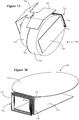
- FIG. 5 illustrates an integrated antenna/battery door module in accordance with any of the embodiments disclosed herein.
- the antenna/battery door module 500 shown in Figure 5 includes a battery door 508 having an exterior surface 517 and an opposing interior surface 519.
- a battery 540 is affixed to the interior surface 519 of the battery door 508.
- An antenna 520 is attached to the battery door 508 in a manner previously described.
- the antenna 520 is implemented as a PIFA.
- a first coil 510a of a separable transformer is connected to the antenna 520 and disposed on the inner surface 519 of the battery door 508.
- the antenna/battery door module 500 When the antenna/battery door module 500 is attached to the faceplate of a hearing device and moved to its closed configuration, the first coil 510a aligns with and magnetically couples to a corresponding second coil (not shown) disposed on the faceplate or other support structure/component on or within the shell of the hearing device.
- the antenna/battery module 500 can be implemented as a field replaceable module (e.g., attachable to and detachable from the faceplate hinge by the wearer, a technician or a hearing instrument professional).
- FIG. 6 illustrates an integrated antenna/battery door module in accordance with other embodiments.
- the antenna/battery door module 600 shown in Figure 6 includes a battery door 608 which supports an antenna 620 and a first coil 610a of a separable transformer connected to the antenna 620.
- the antenna/battery door module 600 is shown attached to a faceplate 607 by a hinge, and is depicted in its open configuration relative to an opening 609 of the faceplate 607.
- the antenna 620 is shown disposed on an inner surface 619 of the battery door 608.
- the antenna 620 is implemented as a meandered monopole.
- the first coil 610a is configured as a loop or spiral, either of which may be square, square loop connected to one end of the meandered monopole 620.
- the first coil 610a aligns with and magnetically couples to a corresponding second coil (e.g., a corresponding square loop) disposed on or supported by the faceplate 607 or other support structure or component on or within the shell of the hearing device.
- the antenna/battery module 600 can be implemented as a field replaceable module, in which case the battery can be a rechargeable battery.
- FIGS 7A and 7B illustrate an antenna and a magnetically coupled feed arrangement in accordance with any of the embodiments disclosed herein.
- the antenna 700 is shown positioned adjacent a battery 705 (e.g., a 13 or 312 battery, which can be a rechargeable battery).
- the antenna 700 and battery 705 are electrically connected to other components of the hearing device (e.g., radio transceiver, power management circuitry) via flexible electrical circuits (PCB flex) 707 and 709.
- PCB flex flexible electrical circuits
- the antenna 700 shown in Figures 7A and 7B is representative of a patch-type antenna.
- Patch antennas also referred to as rectangular microstrip antennas, are low profile and lightweight making them well-suited for use in ear-worn electronic devices, such as hearing aids and other hearables.
- Various types of patch antennas can be implemented within a hearing device, including a PIFA and an Inverted-F Antenna (IFA).
- the patch-type antenna shown in Figures 7A and 7B is implemented as a PIFA for purposes of illustration.
- the antenna 700 includes a ground plane 702 separated from a conductive patch 704 by a dielectric 706.
- a suitable PCB material for the dielectric 706 can have an isotropic dielectric constant in a range of about 12 to about 13, for example (e.g., TMM13i available from Rogers Corporation). Materials with a dielectric constant in this range or greater are useful to reduce the physical dimensions of the antenna 700 when compared, for example, to the physical dimensions of an antenna that uses air as the dielectric.
- the antenna 700 includes a shorting wall, frame or pin 703 that shorts the patch 704 to the ground plane 702. To achieve a desired antenna response, the antenna 700 may include multiple shorting pins, for example.
- the antenna 700 is fed by a magnetically coupled feed arrangement 710 which includes a first coil 712 and a second coil 714.
- the magnetically coupled feed arrangement 710 is oriented in a plane transverse (e.g., normal) to a plane of the patch 704 and ground plane 702.
- the first coil 712 is connected to a feed arm 708 of the antenna 700.
- the second coil 714 is coupled to a radio transceiver of the hearing device either directly or via a matching network.
- the first and second coils 712, 714 are shown as having a substantially planar configuration (e.g., a flat rectangular or square configuration), and are in close proximity and substantially parallel to one another. In this orientation, the first and second coils 712, 714 are configured to feed the antenna 700 via mutual induction between the first and second coil 712, 714.
- the antenna 700 and first coil 712 can be mounted to a first structure or component of the hearing device, and the second coil 714 can be mounted to a second structure or component of the hearing device.
- the first structure or component supporting the antenna 700 and first coil 712 is movable relative to the structure or component supporting the second coil 714.
- the structure or component supporting the second coil 714 is movable relative to the structure or component supporting the antenna 700 and first coil 712.
- the first and second structures or components are static structures or components of the hearing device.
- the antenna 700 and first coil 712 can be mounted on a movable battery door or drawer supported by a faceplate of the hearing device.
- the second coil 714 can be mounted to a fixed structure or component within the shell of the hearing device.
- the first and second coils 712, 714 are substantially parallel to one another, allowing the antenna 700 to be fed via mutual induction between the first and second coil 712, 714.
- the first and second coils 712, 714 are moved apart from one another (e.g., move substantially non-parallel to one another), which prohibits or inhibits mutual induction between the first and second coils 712, 714.
- FIGs 8A and 8B illustrate an antenna and a magnetically coupled feed arrangement in accordance with any of the embodiments disclosed herein.
- the antenna 800 shown in Figures 8A and 8B is implemented as a PIFA.
- the antenna 800 includes a conductive patch 802 separated from a ground plane 804 by a dielectric (not shown, but see Figure 7A ).
- the antenna 800 includes a shorting wall 803 (which may be a shorting pin) that shorts the patch 802 to the ground plane 804.
- the antenna 800 is fed by a magnetically coupled feed arrangement 810 which includes a first coil 812 and a second coil 814.
- the magnetically coupled feed arrangement 810 is positioned in a void 811 provided in the ground plane 804, and is oriented in a plane parallel to a plane of the ground plane 802.
- the first coil 812 is connected to a feed arm 808 of the antenna 800.
- the second coil 814 is coupled to a radio transceiver of the hearing device either directly or via a matching network.
- the first and second coils 812, 814 are shown as having a planar configuration (e.g., a flat rectangular or square configuration), and are in close proximity and substantially parallel to one another. In this orientation, the first and second coils 812, 814 are configured to feed the antenna 800 via mutual induction between the first and second coil 812, 814.
- the antenna 800 and first coil 812 can be mounted to a first structure or component of the hearing device, and the second coil 814 can be mounted to a second structure or component of the hearing device.
- the first structure or component supporting the antenna 800 and first coil 812 is movable relative to the structure or component supporting the second coil 814.
- the structure or component supporting the second coil 814 is movable relative to the structure or component supporting the antenna 800 and first coil 812.
- the first and second structures or components are static structures or components of the hearing device.
- the antenna 800 and first coil 812 can be mounted on a movable battery door or drawer supported by a faceplate of the hearing device.
- the second coil 814 can be mounted to a fixed structure or component within the shell of the hearing device.
- the first and second coils 812, 814 are substantially parallel to one another, allowing the antenna 800 to be fed via mutual induction between the first and second coil 812, 814.
- the first and second coils 812, 814 are moved apart from one another (e.g., move substantially non-parallel to one another), which prohibits or inhibits mutual induction between the first and second coils 812, 814.
- FIG. 9A illustrates a magnetically coupled feed arrangement in accordance with any of the embodiments disclosed herein.
- the magnetically coupled feed arrangement 900a includes a first coil 902 disposed on a first substrate 904, and a second coil 912 disposed on a second substrate 914.
- the first and second substrates 904, 914 can be rigid or flexible substrates (e.g., rigid or flexible PCB substrates).
- the magnetically coupled feed arrangement 900a includes one or more alignment features 920 configured to facilitate alignment between the first and second coils 902, 912 when the first and second substrates 904, 914 are moved into close proximity.
- the alignment features 920 can include a peg 922 and hole 924 arrangement, whereby alignment between the first and second coils 902, 912 is achieved when one or more pegs 922 are received by one or more holes 924.
- Other types of alignment features 920 are contemplated, such as a ridge and groove arrangement provided on the opposing surfaces of the first and second substrates 904, 914.
- Figure 9B illustrates a variation of the magnetically coupled feed arrangement shown in Figure 9A .
- the magnetically coupled feed arrangement 900b includes a substrate 930 disposed between the first and second coils 902, 912 supported by the first and second substrates 904, 914, respectively.
- the substrate 930 is configured to increase magnetic coupling between the first and second coils 902, 912.
- the substrate 930 can comprise high permeability material, such as Mu-Metal, ferrite, or ferrite loaded elastomer.
- the magnetically coupled feed arrangement 900b includes one or more alignment features 920 configured to facilitate alignment between the first and second coils 902, 912 when the first and second substrates 904, 914 are moved in to close proximity with the substrate 930.
- the substrate 930 can be affixed to one of the first and second substrates 904, 914 or be supported by a structure or component separate from the first and second substrates 904, 914.
- the alignment features 920 can be the same as those discussed hereinabove (e.g., one or more pegs 922 received by one or more holes 924).
- FIG 10 illustrates a magnetically coupled feed arrangement in accordance with any of the embodiments disclosed herein.
- the magnetically coupled feed arrangement 1000 includes a primary coil 1002 and a secondary coil 1004 which define components of a transformer, such as a separable transformer discussed previously.
- the primary coil 1002 is typically coupled to a radio transceiver (e.g., source) of the hearing device, and the secondary coil 1004 is typically coupled to the antenna (e.g., load) of the hearing device.
- the primary coil 1002 comprises windings having M turns, and the secondary coil 1004 comprises windings having N turns. According to some embodiments, M and N are selected to enhance impedance matching between the transceiver and the antenna of the hearing device.
- FIGS 11A through 11D illustrate variations of a magnetically coupled feed arrangement which incorporates impedance matching components in accordance with any of the embodiments disclosed herein.
- Each of the magnetically coupled feed arrangements 1100a-1100d includes a primary coil 1102 and a secondary coil 1104 which define components of a transformer, such as a separable transformer.
- the primary coil 1102 is typically coupled to a radio transceiver (e.g., source) of the hearing device
- the secondary coil 1104 is typically coupled to the antenna (e.g., load) of the hearing device.
- impedance matching can be accomplished using capacitors on the ends of the transformer coils 1102, 1104. These capacitors, referred to as tuning capacitors, can be incorporated in series or in shunt (in parallel).
- the tuning capacitors incorporated in the magnetically coupled feed arrangements 1100a-1100d provide for a tuned transformer (both input and output being tuned to resonance) that typically has much higher coupling than an untuned transformer. This is especially true if the Q of the tuned LCR circuits is high, and if the mutual inductance of the two coils 1102, 1104 is not near 1.
- a first tuning capacitor, C1 is coupled to the primary coil 1102, and a second tuning capacitor, C2, is coupled to the secondary coil 1104.
- the first tuning capacitor, C1 can have a capacitance selected to achieve resonance with the primary coil 1102.
- the second tuning capacitor, C2 can have a capacitance selected to achieve resonance with the secondary coil 1104.
- FIGs 11A-11D illustrate four representative impedance matching configurations.
- capacitor C1 is connected to the ends of the primary coil 1102 in shunt, and capacitor C2 is connected to an end of the secondary coil 1104 in series.
- capacitor C1 is connected to the ends of the primary coil 1102 in shunt, and capacitor C2 is connected to the ends of the second coil 1104 in shunt.
- capacitor C1 is connected to an end of the primary coil 1102 in series, and capacitor C2 is connected to ends of the secondary coil 1104 in shunt.
- capacitor C1 is connected to an end of the primary coil 1102 in series, and capacitor C2 is connected to an end of the secondary coil 1104 in series. It is noted that impedance matching can be enhanced by incorporating the tuning capacitors illustrated in Figures 11A-11D in combination with appropriate selection of the number of turns (M and N) of the windings of the primary and secondary coils 1102, 1104.
- a magnetically coupled feed arrangement can incorporate a balun in accordance with any of the embodiments disclosed herein.
- a balun can be considered a type of transformer that is used to convert an unbalanced signal to a balanced signal or vice a versa.
- a balun can be integrated into the magnetically coupled feed arrangement to interface a balanced RF port (e.g., primary coupling port 1204) of a radio transceiver to an unbalanced antenna (e.g., antenna 1202 coupled to secondary coupling port 1206), such as that shown in Figure 12A .
- a balun can be integrated into the magnetically coupled feed arrangement to interface an unbalanced RF port (e.g., primary coupling port 1214) of the transceiver with a balanced antenna (e.g., antenna 1212 coupled to secondary coupling port 1216), such as that illustrated in Figure 12B .
- a balun can include an inductive feed-line coupler, which is a particular type of RF transformer, having a center-tap 1216 connected to ground on the balanced circuit side (e.g., see Figure 12B ).
- an N:M turns ratio balun can be used as a combination balun/impedance-transformer/magnetic feed-line coupler according to some embodiments.
- Coupled refers to elements being attached to each other either directly (in direct contact with each other) or indirectly (having one or more elements between and attaching the two elements). Either term may be modified by "operatively” and “operably,” which may be used interchangeably, to describe that the coupling or connection is configured to allow the components to interact to carry out at least some functionality (for example, a radio chip may be operably coupled to an antenna element to provide a radio frequency electromagnetic signal for wireless communication).
- orientation such as “top,” “bottom,” “side,” and “end,” are used to describe relative positions of components and are not meant to limit the orientation of the embodiments contemplated.
- an embodiment described as having a “top” and “bottom” also encompasses embodiments thereof rotated in various directions unless the content clearly dictates otherwise.
- references to "one embodiment,” “an embodiment,” “certain embodiments,” or “some embodiments,” etc. means that a particular feature, configuration, composition, or characteristic described in connection with the embodiment is included in at least one embodiment of the disclosure. Thus, the appearances of such phrases in various places throughout are not necessarily referring to the same embodiment of the disclosure. Furthermore, the particular features, configurations, compositions, or characteristics may be combined in any suitable manner in one or more embodiments.
- phrases "at least one of,” “comprises at least one of,” and “one or more of' followed by a list refers to any one of the items in the list and any combination of two or more items in the list.
Landscapes
- Engineering & Computer Science (AREA)
- Physics & Mathematics (AREA)
- Acoustics & Sound (AREA)
- Signal Processing (AREA)
- Health & Medical Sciences (AREA)
- General Health & Medical Sciences (AREA)
- Neurosurgery (AREA)
- Otolaryngology (AREA)
- Computer Networks & Wireless Communication (AREA)
- Manufacturing & Machinery (AREA)
- Support Of Aerials (AREA)
Abstract
Description
- This application relates generally to ear-worn electronic devices, including hearing devices, hearing aids, personal amplification devices, and other hearables.
- Hearing devices provide sound for the wearer. Some examples of hearing devices are headsets, hearing aids, speakers, cochlear implants, bone conduction devices, and personal listening devices. For example, hearing aids provide amplification to compensate for hearing loss by transmitting amplified sounds to a wearer's ear canals. Hearing devices may be capable of performing wireless communication with other devices, such as receiving streaming audio from a streaming device via a wireless link. Wireless communication may also be performed for programming the hearing device and transmitting information from the hearing device. For performing such wireless communication, hearing devices such as hearing aids can include a wireless transceiver and an antenna.
- Embodiments are directed to an ear-worn electronic device configured to be worn by a wearer. The device comprises an enclosure configured for at least partial insertion into an ear canal of the wearer. The enclosure comprises a preformed shape or a shapeable material that conforms to a shape of the wearer's ear canal. The enclosure also comprises a faceplate and a battery door supported by and movable relative to the faceplate. A processor is disposed in the enclosure. A speaker or a receiver is operably coupled to the processor. A radio frequency transceiver is disposed in the enclosure and operably coupled to the processor. An antenna is supported by or integral to the battery door. A magnetically coupled feed arrangement comprises a separable transformer. The separable transformer comprises a first coil coupled to the antenna and supported by the battery door, and a second coil coupled to the transceiver and supported by the faceplate, a structure of or within the enclosure or a component in the enclosure. A conductor of the second coil is physically and electrically separated from a conductor of the first coil. The feed arrangement is configured to feed the antenna via mutual inductance between the first and second coils.
- Embodiments are directed to an ear-worn electronic device configured to be worn by a wearer. The device comprises an enclosure configured for at least partial insertion into an ear canal of the wearer. The enclosure comprises a faceplate and a shell having a preformed shape or comprising a shapeable material that conforms to a shape of the wearer's ear canal. A processor is disposed in the enclosure. A speaker or a receiver is operably coupled to the processor. A radio frequency transceiver is disposed in the enclosure and operably coupled to the processor. An antenna is supported by or integral to the faceplate. The antenna comprises a radiating element, a ground plane, and a substrate comprising dielectric material disposed between the radiating element and the ground plane. A magnetically coupled feed arrangement comprises a separable transformer. The separable transformer comprises a first coil coupled to the antenna and supported by the faceplate, and a second coil coupled to the transceiver and supported by the faceplate, a structure of or within the shell or a component in the shell. A conductor of the second coil is physically and electrically separated from a conductor of the first coil. The feed arrangement is configured to feed the antenna via mutual inductance between the first and second coils.
- Embodiments are directed to an ear-worn electronic device configured to be worn by a wearer. The device comprises an enclosure configured to be supported at, by, in or on the wearer's ear. A processor is disposed in the enclosure. A speaker or a receiver is coupled to the processor. A radio frequency transceiver is disposed in the enclosure and coupled to the processor. An antenna is disposed in or on the enclosure. A magnetically coupled feed arrangement comprises a separable transformer. The separable transformer comprises a first coil coupled to the antenna and a second coil coupled to the transceiver, wherein a conductor of the second coil is physically and electrically separated from a conductor of the first coil. The feed arrangement is configured to feed the antenna via mutual inductance between the first and second coils
- The above summary is not intended to describe each disclosed embodiment or every implementation of the present disclosure. The figures and the detailed description below more particularly exemplify illustrative embodiments.
- Throughout the specification reference is made to the appended drawings wherein:
-
Figures 1A and 1B illustrate an ear-worn electronic device arrangement incorporating a magnetically coupled feed for an antenna of the device in accordance with any of the embodiments disclosed herein; -
Figures 2A and2B illustrate a custom hearing device system which incorporates a magnetically coupled feed for an antenna of the device in accordance with any of the embodiments disclosed herein; -
Figure 3A illustrates a hearing device which incorporates an antenna and a magnetically coupled feed arrangement in accordance with any of the embodiments disclosed herein; -
Figure 3B illustrates a hearing device which incorporates an antenna and a magnetically coupled feed arrangement in accordance with any of the embodiments disclosed herein; -
Figures 4A through 4C illustrate an antenna and a coupling element of a magnetically coupled feed arrangement mounted on a battery door of a hearing device faceplate in accordance with any of the embodiments disclosed herein; -
Figure 5 illustrates an integrated antenna/battery door module in accordance with any of the embodiments disclosed herein; -
Figure 6 illustrates an integrated antenna/battery door module in accordance with any of the embodiments disclosed herein; -
Figures 7A and 7B illustrate an antenna and a magnetically coupled feed arrangement in accordance with any of the embodiments disclosed herein; -
Figures 8A and 8B illustrate an antenna and a magnetically coupled feed arrangement in accordance with any of the embodiments disclosed herein; -
Figure 9A illustrates a magnetically coupled feed arrangement in accordance with any of the embodiments disclosed herein; -
Figure 9B illustrates a magnetically coupled feed arrangement in accordance with any of the embodiments disclosed herein; -
Figure 10 illustrates a magnetically coupled feed arrangement in accordance with any of the embodiments disclosed herein; -
Figures 11A through 11D illustrate variations of a magnetically coupled feed arrangement which incorporates impedance matching components in accordance with any of the embodiments disclosed herein; -
Figure 12A illustrates an unbalanced antenna of a hearing device which can be interfaced with a balanced RF port of a radio transceiver via a balun in accordance with any of the disclosed embodiments; and -
Figure 12B illustrates a balanced antenna of a hearing device which can be interfaced with an unbalanced RF port of a radio transceiver via a balun in accordance with any of the disclosed embodiments. - The figures are not necessarily to scale. Like numbers used in the figures refer to like components. However, it will be understood that the use of a number to refer to a component in a given figure is not intended to limit the component in another figure labeled with the same number.
- It is understood that the embodiments described herein may be used with any ear-worn or ear-level electronic device without departing from the scope of this disclosure. The devices depicted in the figures are intended to demonstrate the subject matter, but not in a limited, exhaustive, or exclusive sense. Ear-worn electronic devices (also referred to herein as "hearing devices"), such as hearables (e.g., wearable earphones, ear monitors, and earbuds), hearing aids, hearing instruments, and hearing assistance devices, typically include an enclosure, such as a housing or shell, within which internal components are disposed. Typical components of a hearing device can include a processor (e.g., a digital signal processor or DSP), memory circuitry, power management circuitry, one or more communication devices (e.g., a radio, a near-field magnetic induction (NFMI) device), one or more antennas, one or more microphones, and a receiver/speaker, for example. Hearing devices can incorporate a long-range communication device, such as a Bluetooth® transceiver or other type of radio frequency (RF) transceiver. A communication device (e.g., a radio or NFMI device) of a hearing device can be configured to facilitate communication between a left ear device and a right ear device of the hearing device.
- Hearing devices of the present disclosure can incorporate an antenna coupled to a high-frequency transceiver, such as a 2.4 GHz radio. The RF transceiver can conform to an IEEE 802.11 (e.g., WiFi®) or Bluetooth® (e.g., BLE, Bluetooth® 4. 2 or 5.0) specification, for example. It is understood that hearing devices of the present disclosure can employ other transceivers or radios, such as a 900 MHz radio. Hearing devices of the present disclosure can be configured to receive streaming audio (e.g., digital audio data or files) from an electronic or digital source. Representative electronic/digital sources (e.g., accessory devices) include an assistive listening system, a TV streamer, a radio, a smartphone, a laptop, a cell phone/entertainment device (CPED) or other electronic device that serves as a source of digital audio data or other types of data files. Hearing devices of the present disclosure can be configured to effect bi-directional communication (e.g., wireless communication) of data with an external source, such as a remote server via the Internet or other communication infrastructure. Hearing devices that include a left ear device and a right ear device can be configured to effect bi-directional communication (e.g., wireless communication) therebetween, so as to implement ear-to-ear communication between the left and right ear devices.
- The term hearing device of the present disclosure refers to a wide variety of ear-level electronic devices that can aid a person with impaired hearing. The term hearing device also refers to a wide variety of devices that can produce processed sound for persons with normal hearing. Hearing devices of the present disclosure include hearables (e.g., wearable earphones, headphones, earbuds, virtual reality headsets), hearing aids (e.g., hearing instruments), cochlear implants, and bone-conduction devices, for example. Hearing devices include, but are not limited to, behind-the-ear (BTE), in-the-ear (ITE), in-the-canal (ITC), invisible-in-canal (IIC), receiver-in-canal (RIC), receiver-in-the-ear (RITE) or completely-in-the-canal (CIC) type hearing devices or some combination of the above. Throughout this disclosure, reference is made to a "hearing device," which is understood to refer to a system comprising a single left ear device, a single right ear device, or a combination of a left ear device and a right ear device.
- Ear-worn electronic devices configured for wireless communication, such as hearing aids and other types of hearing devices, can be relatively small in size. Custom hearing devices, such as ITE, ITC, and CIC devices for example, are quite small in size. In the manufacture of a custom hearing device, for example, an ear impression or ear mold is taken for a particular wearer and processed to construct the housing of the hearing device. Because custom hearing devices are designed to be partially or fully inserted into a wearer's ear canal, the housing is necessarily quite small. In order to implement a functional wireless platform (e.g., @ 2.4 GHz), the antenna must be small enough to fit within such devices. The severe space limitations within the housing of an ear-worn electronic device impose a physical challenge on designing the antenna.
- For some hearing devices, it is desirable to mount the antenna on a movable door or drawer which is used to insert and remove a battery into/from the hearing device. Mounting the antenna to the movable battery door of relatively small hearing devices, such as custom hearing aids, provides the opportunity to significantly reduce the size of the hearing device. However, feeding the antenna in this location presents a unique challenge, since the feed cannot have a soldered physical connection. This is particularly important in order for the battery door to be field replaceable, which is highly desirable for some hearing devices. One approach to implementing an antenna arrangement with a connection-less feed involves the use of scratch pads, which would likely shorten the life of the hearing device by an unacceptable degree. Scratch pads can also negatively impact the antenna performance at high frequencies (e.g., @ 2.4 GHz).
- Embodiments of the disclosure are directed to an antenna arrangement of a hearing device which includes a magnetically coupled feed for the antenna. A magnetically coupled feed for the antenna of a hearing device eliminates the need for a physical (e.g., soldered) connection between the antenna and a transceiver (e.g., via a matching network) of the hearing device. A magnetically coupled feed for the antenna of a hearing device provides the flexibility of mounting different components of the antenna arrangement on different structures or components of the hearing device. For example, some components of the antenna arrangement can be mounted on a fixed structure of the hearing device, while other antenna components can be mounted on a movable structure of the hearing device. More particularly, the antenna and a first section of the feed arrangement can be mounted on a movable structure of the hearing device. A second section of the feed arrangement is coupled to a transceiver, and can be mounted on a fixed (or, alternatively, a movable) structure of the hearing device. When moved into close proximity to one another, such as by moving the movable structure into proximity to the fixed structure, the first and second feed sections serve as a magnetically coupled feed for the antenna.
- According to any of the embodiments disclosed herein, a magnetically coupled feed arrangement comprises at least a first section and a second section, such that a conductor of the first section is physically and electrically separated from a conductor of the second section. More particularly, a conductor of the first section is not electrically (as opposed to magnetically or electromagnetically) connected to a conductor of the second section, such that the conductors (e.g., metal components) of the first and section sections are not in physical (e.g., mechanical) contact with one another. It is understood that conductors of the first and/or second sections can be covered by thin insulating material (e.g., polyimide), and this insulating material can be in physical contact, while the conductors (e.g., metal components) of the first and second sections remain physically separated from one another (e.g., no metal-to-metal contact between the first and second sections).
-
Figures 1A and 1B illustrate various components of a representative hearing device arrangement in accordance with any of the embodiments disclosed herein.Figures 1A and 1B illustrate first andsecond hearing devices single hearing device second hearing devices second hearing devices second hearing devices - The first and
second hearing devices enclosure 101 configured for placement, for example, over or on the ear, entirely or partially within the external ear canal (e.g., between the pinna and ear drum) or behind the ear. Disposed within theenclosure 101 is aprocessor 102 which incorporates or is coupled to memory circuitry. Theprocessor 102 can include or be implemented as a multi-core processor, a digital signal processor (DSP), an audio processor or any combination of these processors. For example, theprocessor 102 may be implemented in a variety of different ways, such as with a mixture of discrete analog and digital components that include a processor configured to execute programmed instructions contained in a processor-readable storage medium (e.g., solid-state memory, e.g., Flash). - The
processor 102 is coupled to a wireless transceiver 104 (also referred to herein as a radio), such as a BLE transceiver. Thewireless transceiver 104 is operably coupled to anantenna 106 configured for transmitting and receiving radio signals. Theantenna 106, according to any of the embodiments disclosed herein, is mounted to a movable (e.g., separable, removable)section 105 of the enclosure orshell 101. Themovable section 105 can be a plate (e.g., a faceplate) that covers a major opening of the shell of theenclosure 101. For example, the faceplate can be attached to the shell during hearing device assembly. The faceplate is typically a structure separate from the shell and is not designed to be separable by the wearer. By way of further example, themovable section 105 can be a battery door or drawer of a faceplate of theenclosure 101. In such a configuration, the faceplate is fixed to the shell of theenclosure 101 and theantenna 106 travels with the battery door as the battery door is moved into and out of the faceplate (see, e.g.,Figures 4A-4C ). In some configurations, the faceplate and/or the battery door assembly can be a field replaceable component. - The
antenna 106 is operably coupled to thewireless transceiver 104 by a magnetically coupledfeed arrangement 107. Thewireless transceiver 104 can include or be coupled to a matching network, and the matching network can be coupled to the magnetically coupledfeed arrangement 107. The magnetically coupledfeed arrangement 107 comprises multiple coupling elements. At least one of the coupling elements is mounted on or supported by themovable section 105 of theenclosure 101, and at least one other coupling element is mounted on or supported by a structure (e.g., a flexible electrical circuit, a spine structure, an enclosure wall) of the fixed portion (e.g., shell) of theenclosure 101. - According to any of the embodiments disclosed herein, the magnetically coupled
feed arrangement 107 comprises a separable transformer, such that elements of the transformer are movable relative to one another. For example, the separable transformer can include afirst coupling element 107a supported on or by themovable section 105 of theenclosure 101. Asecond coupling element 107b can be mounted on or supported by a structure of the fixed portion of theenclosure 101. The magnetically coupledfeed arrangement 107 is configured to feed theantenna 106 via mutual inductance between the first andsecond coupling elements second coupling elements feed arrangement 107 eliminates a physical connection between theantenna 106 and the transceiver 104 (or a matching network), allowing theantenna 106 to be mounted on amovable section 105 of theenclosure 101. - In some embodiments, the
hearing devices movable section 105. In such embodiments, theantenna 106 can be mounted on or within theenclosure 101 and coupled to thetransceiver 104 via the magnetically coupledfeed arrangement 107. For example, theantenna 106 can be implemented on a laser direct structuring (LDS) structure one or inside of theenclosure 101. By way of further examples, theantenna 106 can be integrated into the spine or a flexible electrical circuit disposed within theenclosure 101. In each of these embodiments, theantenna 106 is coupled to thetransceiver 104 via the magnetically coupledfeed arrangement 107, which need not include a separable transformer. - The
wireless transceiver 104 andantenna 106 can be configured to enable ear-to-ear communication between the twohearing devices battery 110 or other power source (rechargeable or conventional) is provided within theenclosure 101 and configured to provide power to the various components of thehearing devices battery 110 can be inserted into and removed from theenclosure 101 via a battery door or drawer. A speaker orreceiver 108 is coupled to an amplifier (not shown) and theprocessor 102. The speaker orreceiver 108 is configured to generate sound which is communicated to the wearer's ear. - In some embodiments, the
hearing devices microphone 112 mounted on or inside theenclosure 101. Themicrophone 112 may be a single microphone or multiple microphones, such as a microphone array. Themicrophone 112 can be coupled to a preamplifier (not shown), the output of which is coupled to theprocessor 102. Themicrophone 112 receives sound waves from the environment and converts the sound into an input signal. The input signal is amplified by the preamplifier and sampled and digitized by an analog-to-digital converter of theprocessor 102, resulting in a digitized input signal. In some embodiments (e.g., hearing aids), the processor 102 (e.g., DSP circuitry) is configured to process the digitized input signal into an output signal in a manner that compensates for the wearer's hearing loss. When receiving an audio signal from an external source, thewireless transceiver 104 may produce a second input signal for the DSP circuitry of theprocessor 102 that may be combined with the input signal produced by themicrophone 112 or used in place thereof. In other embodiments, (e.g., hearables), theprocessor 102 can be configured to process the digitized input signal into an output signal in a manner that is tailored or optimized for the wearer (e.g., based on wearer preferences). The output signal is then passed to an audio output stage that drives the speaker orreceiver 108, which converts the output signal into an audio output. - Some embodiments are directed to a custom hearing aid, such as an ITC, CIC, or IIC hearing aid. For example, some embodiments are directed to a custom hearing aid which includes a wireless transceiver and an antenna arrangement configured to operate in the 2.4 GHz ISM frequency band or other applicable communication band (referred to as the "Bluetooth® band" herein). As was discussed previously, creating a robust antenna arrangement for a 2.4 GHz custom hearing aid represents a significant engineering challenge. A custom hearing aid is severely limited in space. Provision of the magnetically coupled
feed arrangement 107 allows theantenna 106 to be mounted on themovable battery door 105, which provides for a significant reduction in the overall size of thehearing device enclosure 101 while delivering good antenna performance. -
Figures 2A and2B illustrate a custom hearing aid system which incorporates an antenna and a magnetically coupled feed arrangement in accordance with any of the embodiments disclosed herein. Thehearing aid system 200 shown inFigures 2A and2B includes two hearing devices, e.g., left 201a and right 201b side hearing devices, configured to wirelessly communicate with each other and external devices and systems.Figure 2A conceptually illustrates functional blocks of thehearing devices Figure 2A does not necessarily indicate actual locations of components that implement these functional blocks within thehearing devices Figure 2B is a block diagram of components that may be disposed at least partially within theenclosure hearing device - Each
hearing device physical enclosure enclosure enclosure external side internal side enclosure shell faceplate shell shell faceplate battery door external side enclosure battery enclosure battery electronic circuitry shell antenna faceplate battery door feed arrangement antenna electronic circuitry - As illustrated in
Figures 2A and2B , thehearing device more microphones 251a, 251b configured to pick up acoustic signals and to transduce the acoustic signals into microphone electrical signals. The electrical signals generated by themicrophones 251a, 251b may be conditioned by an analog front end 231 (seeFigure 2B ) by filtering, amplifying and/or converting the microphone electrical signals from analog to digital signals so that the digital signals can be further processed and/or analyzed by theprocessor 260. Theprocessor 260 may perform signal processing and/or control various tasks of thehearing device processor 260 comprises a DSP that may include additional computational processing units operating in a multi-core architecture. - The
processor 260 is configured to control wireless communication between thehearing devices antenna transceiver 232. The wireless communication may include, for example, audio streaming data and/or control signals. Thetransceiver 232 has a receiver portion that receives communication signals from theantenna processor 260 for further processing. Thetransceiver 232 also includes a transmitter portion that modulates output signals from theprocessor 260 for transmission via theantenna microphone 251a, 251b and/or wireless communication received via theantenna processor 260 and converted to acoustic signals played to the wearer'sear 299 via aspeaker -
Figure 3A illustrates a hearing device which incorporates an antenna and a magnetically coupled feed arrangement in accordance with any of the embodiments disclosed herein. Thehearing device 300a shown inFigure 3A includes anenclosure 301 within which various components are housed. Thehearing device 300a includes anantenna 302 operably coupled to atransceiver 308 via a magnetically coupledfeed arrangement 303a. Thetransceiver 308 is coupled to aprocessor 310, and a speaker orreceiver 312 is also coupled to theprocessor 310. In some embodiments, thehearing device 300a includes one or more microphones. The magnetically coupledfeed arrangement 303a comprises a transformer 304-1. The transformer 304-1 includes afirst coil 304a, coupled to theantenna 302, and asecond coil 304b, operably coupled to thetransceiver 308. In some embodiments, thesecond coil 304b is coupled to amatching network 306, and thematching network 306 is coupled to thetransceiver 308. The transformer 304-1 defines a connection-less (no physical connection) feed for theantenna 302. In some embodiments, the transformer 304-1 need not be a separable transformer. - The
antenna 302 and the first andsecond coils Figures 3A and 3B can be disposed on rigid or flexible substrates (or a combination of rigid and flexible substrates). For example, the first andsecond coils second coils second coils antenna 302 can be disposed on a flexible printed circuit board substrate or a rigid printed circuit board substrate. For example, theantenna 302 and the first andsecond coils antenna 302 and thefirst coil 304a can be disposed on a rigid printed circuit board substrate, and thesecond coil 304b can be disposed on a flexible printed circuit board substrate. -
Figure 3B illustrates a variation of the hearing device shown inFigure 3A . In the embodiment shown inFigure 3B , thehearing device 300b includes anenclosure 301 comprising amovable section 301a. Themovable section 301a represents a component or structure which is movable relative to a fixedsection 301b of theenclosure 301. For example, themovable section 301a can be a battery door or drawer supported by a faceplate of theenclosure 301. The fixedsection 301b can be a flexible electrical circuit, a spine, a wall of theenclosure 301, or other structure or component of theenclosure 301 that remains relatively fixed when themovable section 301a is displaced relative to the fixedsection 301b (e.g., via manipulation by the wearer's fingers). - The
hearing device 300a shown inFigure 3B includes a magnetically coupledfeed arrangement 303b operably coupled to theantenna 302 and the transceiver 308 (e.g., optionally via the matching network 306). The magnetically coupledfeed arrangement 303b comprises a separable transformer 304-2. The separable transformer 304-2 includes afirst coil 304a and asecond coil 304b which are movable relative to one another. Theantenna 302 and thefirst coil 304a are mounted to or supported by themovable section 301a. Thesecond coil 304b is mounted to or supported by the fixedsection 301b. Thefirst coil 304a can be moved away from the second coil to assume a de-coupled configuration, during which theantenna 302 andtransceiver 308 are non-operable for effecting wireless communication. Thefirst coil 304a andsecond coil 304b can be moved into close proximity with one another to assume a magnetically coupled configuration, during which theantenna 302 andtransceiver 308 are operable for effecting wireless communication. -
Figures 4A through 4C illustrate an antenna and a coupling element of a magnetically coupled feed arrangement mounted on a battery door of a hearing device faceplate in accordance with any of the embodiments disclosed herein.Figures 4A through 4C illustrate portions of ahearing device 400 including anenclosure 405 comprising a portion of ashell 406 and afaceplate 407. Thefaceplate 407 comprises a faceplateperipheral region 409 and abattery door 408. Abattery 440 andelectronics 430 are shown disposed within theshell 406. Thebattery 440 is accessible through thebattery door 408. As illustrated inFigure 4B , ahinge 480 connects thebattery door 408 to the faceplateperipheral region 409 allowing thebattery door 408 to rotate open or closed for accessing thebattery 408. -
Figure 4C provides a top view of thefaceplate 407 including the faceplateperipheral region 409,battery door 408, and hinge 480. As best seen in the top view ofFigure 4C , thefaceplate 407 can be approximated by an ellipse or oval although other shapes are contemplated. Thefaceplate 407 extends generally along a longitudinal axis lofp and a lateral axis lafp, where lofp is the longest dimension of thefaceplate 407 and lafp is orthogonal to lofp. Axes lofp and lafp define the plane of thefaceplate 407. The vertical axis, vfp, of the faceplate extends through the faceplate and is orthogonal to lofp and lafp. Thebattery 440 may also be generally in the shape of an ellipse, oval or other suitable shape and may be oriented such a major surface of the battery lies substantially parallel to a plane formed by the longitudinal and lateral axes of thefaceplate 407. In some embodiments, the ground (-) side of thebattery 440 faces toward the user's ear drum and the positive (+) side of thebattery 440 faces away from the user's ear drum (indicated inFIG. 4A ). Alternatively, the battery may be arranged differently in the enclosure, e.g., in the opposite orientation or a major surface of the battery may be arranged substantially perpendicular to the plane of the faceplate. - As shown in
Figures 4A through 4C , theantenna 420 can be disposed in or on thebattery door 408 of thehearing device 400. For example, theantenna 420 may be molded within or on thebattery door 408 or attached to a surface of thebattery door 408, e.g., using an adhesive. In some embodiments, theantenna 420 can be formed as a laser direct structuring (LDS) component on thebattery door 408. A protective coating can be applied to the exterior surface of theantenna 420. In other embodiments, theantenna 420 and thebattery door 408 may be formed as a unitary piece. For example, in some embodiments, theantenna 420 may be coated with a material that hardens over time or with exposure to certain stimuli, and the coated antenna serves as thebattery door 480. As another example, theantenna 420 can be molded into thebattery door 408 in some implementations. - The
antenna 420 can be arranged such that the plane of the antenna extends along the plane of thefaceplate 407. In some embodiments, the plane of theantenna 420 may be substantially parallel or at a slight angle with respect to the plane of thefaceplate 407. Theantenna 420 may comprise a patch (radiating element) and a ground plane, for example theantenna 420 may be implemented as a Planar Inverted-F Antenna (PIFA), as illustrated in connection withFigures 7-8 . When theantenna 420 is configured as a PIFA, and/or any other antenna comprising a patch and a ground plane, the patch (radiating element) and ground plane may be arranged to extend along the plane of thefaceplate 407. - When the
battery 440 is arranged in theenclosure 405 such that the plane, a, of thebattery 440 lies substantially along the plane of thefaceplate 407, thebattery door 408 provides a relatively large area for theantenna 420 at a location where mechanical interference from other structures and/or electromagnetic interference from the device electronics is reduced or eliminated. Thehearing device 400 is configured to be inserted within the user's ear canal with theexternal surface 417 of thefaceplate 407 facing away from the wearer's ear drum (e.g., towards the pinna). When properly inserted within the wearer's ear canal, and depending on the configuration of thehearing device 400, thefaceplate 407 may reside entirely within the ear canal, extend out of the ear canal, or be located close to the opening of the ear canal. Locating theantenna 420 in, on, or near thefaceplate 407 serves to reduce loading of the electromagnetic signal caused by the wearer's head. In the arrangements shown inFigures 4A through 4C , thebattery 440 may provide a shield for theantenna 420. The shield provided by thebattery 440 may achieve further reduction in electromagnetic interference generated by thehearing device electronics 430 that may affect signals on theantenna 420. - As is further shown in
Figures 4A and 4B , theantenna 420 is operatively coupled to atransceiver 432 of theelectronics 430 via a magnetically coupledfeed arrangement 410. The magnetically coupledfeed arrangement 410 includes a separable transformer comprising afirst coil 410a and asecond coil 410b. Thefirst coil 410a is mounted on aninterior surface 419 of thebattery door 408. Thesecond coil 410b is shown mounted on theperipheral region 409 of thefaceplate 407. As was discussed previously, thesecond coil 410b can be mounted on or supported by other structures or components within the shell 406 (e.g., a flexible electrical circuit, a spine structure, a shell wall). - When the
battery door 408 is in a closed configuration (seeFigure 4A ), the first andsecond coils antenna 420. When thebattery door 408 is in an open configuration (seeFigure 4B ), the first andsecond coils -
Figure 5 illustrates an integrated antenna/battery door module in accordance with any of the embodiments disclosed herein. The antenna/battery door module 500 shown inFigure 5 includes abattery door 508 having anexterior surface 517 and an opposinginterior surface 519. Abattery 540 is affixed to theinterior surface 519 of thebattery door 508. Anantenna 520 is attached to thebattery door 508 in a manner previously described. In some embodiments, theantenna 520 is implemented as a PIFA. Afirst coil 510a of a separable transformer is connected to theantenna 520 and disposed on theinner surface 519 of thebattery door 508. When the antenna/battery door module 500 is attached to the faceplate of a hearing device and moved to its closed configuration, thefirst coil 510a aligns with and magnetically couples to a corresponding second coil (not shown) disposed on the faceplate or other support structure/component on or within the shell of the hearing device. The antenna/battery module 500 can be implemented as a field replaceable module (e.g., attachable to and detachable from the faceplate hinge by the wearer, a technician or a hearing instrument professional). -
Figure 6 illustrates an integrated antenna/battery door module in accordance with other embodiments. The antenna/battery door module 600 shown inFigure 6 includes abattery door 608 which supports anantenna 620 and afirst coil 610a of a separable transformer connected to theantenna 620. The antenna/battery door module 600 is shown attached to afaceplate 607 by a hinge, and is depicted in its open configuration relative to anopening 609 of thefaceplate 607. Theantenna 620 is shown disposed on aninner surface 619 of thebattery door 608. In the embodiment shown inFigure 6 , theantenna 620 is implemented as a meandered monopole. Thefirst coil 610a is configured as a loop or spiral, either of which may be square, square loop connected to one end of the meanderedmonopole 620. When the antenna/battery door module 600 is moved to its closed configuration, thefirst coil 610a aligns with and magnetically couples to a corresponding second coil (e.g., a corresponding square loop) disposed on or supported by thefaceplate 607 or other support structure or component on or within the shell of the hearing device. The antenna/battery module 600 can be implemented as a field replaceable module, in which case the battery can be a rechargeable battery. -
Figures 7A and 7B illustrate an antenna and a magnetically coupled feed arrangement in accordance with any of the embodiments disclosed herein. InFigure 7A , theantenna 700 is shown positioned adjacent a battery 705 (e.g., a 13 or 312 battery, which can be a rechargeable battery). Theantenna 700 andbattery 705 are electrically connected to other components of the hearing device (e.g., radio transceiver, power management circuitry) via flexible electrical circuits (PCB flex) 707 and 709. - The
antenna 700 shown inFigures 7A and 7B is representative of a patch-type antenna. Patch antennas, also referred to as rectangular microstrip antennas, are low profile and lightweight making them well-suited for use in ear-worn electronic devices, such as hearing aids and other hearables. Various types of patch antennas can be implemented within a hearing device, including a PIFA and an Inverted-F Antenna (IFA). The patch-type antenna shown inFigures 7A and 7B is implemented as a PIFA for purposes of illustration. - The
antenna 700 includes aground plane 702 separated from aconductive patch 704 by a dielectric 706. A suitable PCB material for the dielectric 706 can have an isotropic dielectric constant in a range of about 12 to about 13, for example (e.g., TMM13i available from Rogers Corporation). Materials with a dielectric constant in this range or greater are useful to reduce the physical dimensions of theantenna 700 when compared, for example, to the physical dimensions of an antenna that uses air as the dielectric. Theantenna 700 includes a shorting wall, frame or pin 703 that shorts thepatch 704 to theground plane 702. To achieve a desired antenna response, theantenna 700 may include multiple shorting pins, for example. - The
antenna 700 is fed by a magnetically coupledfeed arrangement 710 which includes afirst coil 712 and asecond coil 714. InFigures 7A and 7B , the magnetically coupledfeed arrangement 710 is oriented in a plane transverse (e.g., normal) to a plane of thepatch 704 andground plane 702. Thefirst coil 712 is connected to afeed arm 708 of theantenna 700. Thesecond coil 714 is coupled to a radio transceiver of the hearing device either directly or via a matching network. The first andsecond coils second coils antenna 700 via mutual induction between the first andsecond coil - The
antenna 700 andfirst coil 712 can be mounted to a first structure or component of the hearing device, and thesecond coil 714 can be mounted to a second structure or component of the hearing device. In some implementations, the first structure or component supporting theantenna 700 andfirst coil 712 is movable relative to the structure or component supporting thesecond coil 714. In other implementations, the structure or component supporting thesecond coil 714 is movable relative to the structure or component supporting theantenna 700 andfirst coil 712. In further implementations, the first and second structures or components are static structures or components of the hearing device. - By way of example, the
antenna 700 andfirst coil 712 can be mounted on a movable battery door or drawer supported by a faceplate of the hearing device. Thesecond coil 714 can be mounted to a fixed structure or component within the shell of the hearing device. When the battery door is closed, the first andsecond coils antenna 700 to be fed via mutual induction between the first andsecond coil second coils second coils -
Figures 8A and 8B illustrate an antenna and a magnetically coupled feed arrangement in accordance with any of the embodiments disclosed herein. Theantenna 800 shown inFigures 8A and 8B is implemented as a PIFA. Theantenna 800 includes aconductive patch 802 separated from aground plane 804 by a dielectric (not shown, but seeFigure 7A ). Theantenna 800 includes a shorting wall 803 (which may be a shorting pin) that shorts thepatch 802 to theground plane 804. Theantenna 800 is fed by a magnetically coupledfeed arrangement 810 which includes afirst coil 812 and asecond coil 814. InFigures 8A and 8B , the magnetically coupledfeed arrangement 810 is positioned in a void 811 provided in theground plane 804, and is oriented in a plane parallel to a plane of theground plane 802. - The
first coil 812 is connected to afeed arm 808 of theantenna 800. Thesecond coil 814 is coupled to a radio transceiver of the hearing device either directly or via a matching network. The first andsecond coils second coils antenna 800 via mutual induction between the first andsecond coil - The
antenna 800 andfirst coil 812 can be mounted to a first structure or component of the hearing device, and thesecond coil 814 can be mounted to a second structure or component of the hearing device. In some implementations, the first structure or component supporting theantenna 800 andfirst coil 812 is movable relative to the structure or component supporting thesecond coil 814. In other implementations, the structure or component supporting thesecond coil 814 is movable relative to the structure or component supporting theantenna 800 andfirst coil 812. In further implementations the first and second structures or components are static structures or components of the hearing device. - By way of example, the
antenna 800 andfirst coil 812 can be mounted on a movable battery door or drawer supported by a faceplate of the hearing device. Thesecond coil 814 can be mounted to a fixed structure or component within the shell of the hearing device. When the battery door is closed, the first andsecond coils antenna 800 to be fed via mutual induction between the first andsecond coil second coils second coils -
Figure 9A illustrates a magnetically coupled feed arrangement in accordance with any of the embodiments disclosed herein. The magnetically coupledfeed arrangement 900a includes afirst coil 902 disposed on afirst substrate 904, and asecond coil 912 disposed on asecond substrate 914. The first andsecond substrates feed arrangement 900a includes one or more alignment features 920 configured to facilitate alignment between the first andsecond coils second substrates peg 922 andhole 924 arrangement, whereby alignment between the first andsecond coils more pegs 922 are received by one ormore holes 924. Other types of alignment features 920 are contemplated, such as a ridge and groove arrangement provided on the opposing surfaces of the first andsecond substrates -
Figure 9B illustrates a variation of the magnetically coupled feed arrangement shown inFigure 9A . InFigure 9B , the magnetically coupledfeed arrangement 900b includes asubstrate 930 disposed between the first andsecond coils second substrates substrate 930 is configured to increase magnetic coupling between the first andsecond coils substrate 930 can comprise high permeability material, such as Mu-Metal, ferrite, or ferrite loaded elastomer. The magnetically coupledfeed arrangement 900b includes one or more alignment features 920 configured to facilitate alignment between the first andsecond coils second substrates substrate 930. Thesubstrate 930 can be affixed to one of the first andsecond substrates second substrates more pegs 922 received by one or more holes 924). -
Figure 10 illustrates a magnetically coupled feed arrangement in accordance with any of the embodiments disclosed herein. The magnetically coupledfeed arrangement 1000 includes aprimary coil 1002 and asecondary coil 1004 which define components of a transformer, such as a separable transformer discussed previously. Theprimary coil 1002 is typically coupled to a radio transceiver (e.g., source) of the hearing device, and thesecondary coil 1004 is typically coupled to the antenna (e.g., load) of the hearing device. Theprimary coil 1002 comprises windings having M turns, and thesecondary coil 1004 comprises windings having N turns. According to some embodiments, M and N are selected to enhance impedance matching between the transceiver and the antenna of the hearing device. The relationship between M and N turns can be characterized by the formula: Turns Ratio (M:N) = √(Rsource/Rload), with the smaller number of turns being on the side with lower impedance. It is noted that complex impedances can also be transformed according to the formula Z1= Z2/(M/N)2, where Z1 is the source impedance and Z2 is the load impedance. -
Figures 11A through 11D illustrate variations of a magnetically coupled feed arrangement which incorporates impedance matching components in accordance with any of the embodiments disclosed herein. Each of the magnetically coupledfeed arrangements 1100a-1100d includes aprimary coil 1102 and asecondary coil 1104 which define components of a transformer, such as a separable transformer. As discussed previously, theprimary coil 1102 is typically coupled to a radio transceiver (e.g., source) of the hearing device, and thesecondary coil 1104 is typically coupled to the antenna (e.g., load) of the hearing device. As the transformer coils 1102, 1104 are inductive components, impedance matching can be accomplished using capacitors on the ends of the transformer coils 1102, 1104. These capacitors, referred to as tuning capacitors, can be incorporated in series or in shunt (in parallel). - The tuning capacitors incorporated in the magnetically coupled
feed arrangements 1100a-1100d provide for a tuned transformer (both input and output being tuned to resonance) that typically has much higher coupling than an untuned transformer. This is especially true if the Q of the tuned LCR circuits is high, and if the mutual inductance of the twocoils Figures 11A-11D , a first tuning capacitor, C1, is coupled to theprimary coil 1102, and a second tuning capacitor, C2, is coupled to thesecondary coil 1104. The first tuning capacitor, C1, can have a capacitance selected to achieve resonance with theprimary coil 1102. The second tuning capacitor, C2, can have a capacitance selected to achieve resonance with thesecondary coil 1104. -
Figures 11A-11D illustrate four representative impedance matching configurations. InFigure 11A , capacitor C1 is connected to the ends of theprimary coil 1102 in shunt, and capacitor C2 is connected to an end of thesecondary coil 1104 in series. InFigure 11B , capacitor C1 is connected to the ends of theprimary coil 1102 in shunt, and capacitor C2 is connected to the ends of thesecond coil 1104 in shunt. InFigure 11C , capacitor C1 is connected to an end of theprimary coil 1102 in series, and capacitor C2 is connected to ends of thesecondary coil 1104 in shunt. InFigure 11D , capacitor C1 is connected to an end of theprimary coil 1102 in series, and capacitor C2 is connected to an end of thesecondary coil 1104 in series. It is noted that impedance matching can be enhanced by incorporating the tuning capacitors illustrated inFigures 11A-11D in combination with appropriate selection of the number of turns (M and N) of the windings of the primary andsecondary coils - A magnetically coupled feed arrangement can incorporate a balun in accordance with any of the embodiments disclosed herein. In general terms, a balun can be considered a type of transformer that is used to convert an unbalanced signal to a balanced signal or vice a versa. A balun can be integrated into the magnetically coupled feed arrangement to interface a balanced RF port (e.g., primary coupling port 1204) of a radio transceiver to an unbalanced antenna (e.g.,
antenna 1202 coupled to secondary coupling port 1206), such as that shown inFigure 12A . Alternatively, a balun can be integrated into the magnetically coupled feed arrangement to interface an unbalanced RF port (e.g., primary coupling port 1214) of the transceiver with a balanced antenna (e.g.,antenna 1212 coupled to secondary coupling port 1216), such as that illustrated inFigure 12B . According to one embodiment, a balun can include an inductive feed-line coupler, which is a particular type of RF transformer, having a center-tap 1216 connected to ground on the balanced circuit side (e.g., seeFigure 12B ). It is noted that an N:M turns ratio balun can be used as a combination balun/impedance-transformer/magnetic feed-line coupler according to some embodiments. - This document discloses numerous embodiments, including but not limited to the following:
-
Item 1 is an ear-worn electronic device configured to be worn by a wearer, comprising:- an enclosure configured for at least partial insertion into an ear canal of the wearer, the enclosure comprising a preformed shape or a shapeable material that conforms to a shape of the wearer's ear canal, the enclosure comprising a faceplate and a battery door supported by and movable relative to the faceplate;
- a processor disposed in the enclosure;
- a speaker or a receiver operably coupled to the processor;
- a radio frequency transceiver disposed in the enclosure and operably coupled to the processor; and
- an antenna supported by or integral to the battery door; and
- a magnetically coupled feed arrangement comprising a separable transformer, the separable transformer comprising:
- a first coil coupled to the antenna and supported by the battery door; and
- a second coil coupled to the transceiver and supported by the faceplate, a structure of or within the enclosure or a component in the enclosure, wherein a conductor of the second coil is physically and electrically separated from a conductor of the first coil;
- wherein the feed arrangement is configured to feed the antenna via mutual inductance between the first and second coils.
- Item 2 is the device of
item 1, wherein the first coil is moveable relative to the second coil in response to opening and closing of the battery door relative to the faceplate. - Item 3 is the device of
item 1 or item 2, wherein:- the first and second coils have a planar configuration; and
- the first and second coils are substantially parallel to one another when the battery door is in a closed orientation relative to the faceplate.
- Item 4 is the device of
item 1, 2 or 3, wherein the first and second coils are substantially non-parallel to one another when the battery door is in an opened orientation relative to the faceplate. - Item 5 is the device of any preceding item, further comprising a battery, wherein the battery, the battery door, the antenna, and the first coil define a detachable battery door module.
- Item 6 is the device of any preceding item, comprising one or more alignment features configured to facilitate alignment between the first and second coils when the battery door is in a closed orientation.
- Item 7 is the device of any preceding item, wherein the separable transformer comprises a substrate disposed between the first and second coils, the substrate configured to increase magnetic coupling between the first and second coils.
- Item 8 is the device of any preceding item, wherein the magnetically coupled feed arrangement comprises a balun.
- Item 9 is the device of any preceding item, wherein:
- the first coil comprises windings having n turns;
- the second coil comprises windings having m turns; and
- n and m are selected to enhance impedance matching between the transceiver and the antenna.
- Item 10 is the device of any preceding item, wherein:
- a first tuning capacitor is coupled to the first coil;
- a second tuning capacitor is coupled to the second coil;
- the first tuning capacitor has a capacitance selected to achieve resonance with the first coil; and
- the second tuning capacitor has a capacitance selected to achieve resonance with the second coil.
- Item 11 is the device of any preceding item, wherein the first and second coils are disposed on flexible printed circuit board substrates.
- Item 12 is the device of any preceding item, wherein the antenna, the first coil, and the second coil are disposed on flexible printed circuit board substrates.
- Item 13 is the device of any preceding item, wherein:
- the antenna and the first coil are disposed on a rigid printed circuit board substrate; and
- the second coil is disposed on a flexible printed circuit board substrate.
- Item 14 is the device of
item 1, wherein the antenna comprises a patch-type antenna. - Item 15 is the device of
item 1, wherein the antenna comprises a meandered monopole. - Item 16 is the device of
item 1, wherein the antenna comprises an Inverted-F antenna. - Item 17 is an ear-worn electronic device configured to be worn by a wearer, comprising:
- an enclosure configured for at least partial insertion into an ear canal of the wearer, the enclosure comprising a faceplate and a shell having a preformed shape or comprising a shapeable material that conforms to a shape of the wearer's ear canal;
- a processor disposed in the enclosure;
- a speaker or a receiver operably coupled to the processor;
- a radio frequency transceiver disposed in the enclosure and operably coupled to the processor; and
- an antenna supported by or integral to the faceplate, the antenna comprising:
- a radiating element;
- a ground plane; and
- a substrate comprising dielectric material disposed between the radiating element and the ground plane; and
- a magnetically coupled feed arrangement comprising a separable transformer, the separable transformer comprising:
- a first coil coupled to the antenna and supported by the faceplate; and
- a second coil coupled to the transceiver and supported by the faceplate, a structure of or within the shell or a component in the shell, wherein a conductor of the second coil is physically and electrically separated from a conductor of the first coil;
- wherein the feed arrangement is configured to feed the antenna via mutual inductance between the first and second coils.
- Item 18 is the device of item 17, wherein:
- the first and second coils have a planar configuration; and
- the first and second coils are substantially parallel to one another.
- Item 19 is the device of any preceding item, wherein the device is configured as an in-the-ear (ITE), in-the-canal (ITC), invisible-in-canal (IIC) or completely-in-the-canal (CIC) device.
- Item 20 is an ear-worn electronic device configured to be worn by a wearer, comprising:
- an enclosure configured to be supported at, by, in or on the wearer's ear;
- a processor disposed in the enclosure;
- a speaker or a receiver coupled to the processor;
- a radio frequency transceiver disposed in the enclosure and coupled to the processor;
- an antenna disposed in or on the enclosure; and
- a magnetically coupled feed arrangement comprising a separable transformer, the separable transformer comprising:
- a first coil coupled to the antenna; and
- a second coil coupled to the transceiver, wherein a conductor of the second coil is physically and electrically separated from a conductor of the first coil;
- wherein the feed arrangement is configured to feed the antenna via mutual inductance between the first and second coils.
- Item 21 is the device of item 20, wherein at least one of the first and second coils is movable relative to the other of the first and second coils.
- Item 22 is the device of item 20 or item 21, wherein:
- the first and second coils have a planar configuration; and
- the first and second coils are substantially parallel to one another.
- Although reference is made herein to the accompanying set of drawings that form part of this disclosure, one of at least ordinary skill in the art will appreciate that various adaptations and modifications of the embodiments described herein are within, or do not depart from, the scope of this disclosure. For example, aspects of the embodiments described herein may be combined in a variety of ways with each other. Therefore, it is to be understood that, within the scope of the appended claims, the claimed invention may be practiced other than as explicitly described herein.
- All references and publications cited herein are expressly incorporated herein by reference in their entirety into this disclosure, except to the extent they may directly contradict this disclosure. Unless otherwise indicated, all numbers expressing feature sizes, amounts, and physical properties used in the specification and claims may be understood as being modified either by the term "exactly" or "about." Accordingly, unless indicated to the contrary, the numerical parameters set forth in the foregoing specification and attached claims are approximations that can vary depending upon the desired properties sought to be obtained by those skilled in the art utilizing the teachings disclosed herein or, for example, within typical ranges of experimental error.
- The recitation of numerical ranges by endpoints includes all numbers subsumed within that range (e.g. 1 to 5 includes 1, 1.5, 2, 2.75, 3, 3.80, 4, and 5) and any range within that range. Herein, the terms "up to" or "no greater than" a number (e.g., up to 50) includes the number (e.g., 50), and the term "no less than" a number (e.g., no less than 5) includes the number (e.g., 5).
- The terms "coupled" or "connected" refer to elements being attached to each other either directly (in direct contact with each other) or indirectly (having one or more elements between and attaching the two elements). Either term may be modified by "operatively" and "operably," which may be used interchangeably, to describe that the coupling or connection is configured to allow the components to interact to carry out at least some functionality (for example, a radio chip may be operably coupled to an antenna element to provide a radio frequency electromagnetic signal for wireless communication).
- Terms related to orientation, such as "top," "bottom," "side," and "end," are used to describe relative positions of components and are not meant to limit the orientation of the embodiments contemplated. For example, an embodiment described as having a "top" and "bottom" also encompasses embodiments thereof rotated in various directions unless the content clearly dictates otherwise.
- Reference to "one embodiment," "an embodiment," "certain embodiments," or "some embodiments," etc., means that a particular feature, configuration, composition, or characteristic described in connection with the embodiment is included in at least one embodiment of the disclosure. Thus, the appearances of such phrases in various places throughout are not necessarily referring to the same embodiment of the disclosure. Furthermore, the particular features, configurations, compositions, or characteristics may be combined in any suitable manner in one or more embodiments.
- The words "preferred" and "preferably" refer to embodiments of the disclosure that may afford certain benefits, under certain circumstances. However, other embodiments may also be preferred, under the same or other circumstances. Furthermore, the recitation of one or more preferred embodiments does not imply that other embodiments are not useful and is not intended to exclude other embodiments from the scope of the disclosure.
- As used in this specification and the appended claims, the singular forms "a," "an," and "the" encompass embodiments having plural referents, unless the content clearly dictates otherwise. As used in this specification and the appended claims, the term "or" is generally employed in its sense including "and/or" unless the content clearly dictates otherwise.
- As used herein, "have," "having," "include," "including," "comprise," "comprising" or the like are used in their open-ended sense, and generally mean "including, but not limited to." It will be understood that "consisting essentially of," "consisting of," and the like are subsumed in "comprising," and the like. The term "and/or" means one or all of the listed elements or a combination of at least two of the listed elements.
- The phrases "at least one of," "comprises at least one of," and "one or more of' followed by a list refers to any one of the items in the list and any combination of two or more items in the list.
Claims (15)
- An ear-worn electronic device configured to be worn by a wearer, comprising:an enclosure configured to be supported at, by, in or on the wearer's ear;a processor disposed in the enclosure;a speaker or a receiver coupled to the processor;a radio frequency transceiver disposed in the enclosure and coupled to the processor;an antenna disposed in or on the enclosure; anda magnetically coupled feed arrangement comprising a separable transformer, the separable transformer comprising:a first coil coupled to the antenna; anda second coil coupled to the transceiver, wherein a conductor of the second coil is physically and electrically separated from a conductor of the first coil;wherein the feed arrangement is configured to feed the antenna via mutual inductance between the first and second coils.
- An ear-worn electronic device configured to be worn by a wearer, comprising:an enclosure configured for at least partial insertion into an ear canal of the wearer, the enclosure comprising a preformed shape or a shapeable material that conforms to a shape of the wearer's ear canal, the enclosure comprising a faceplate and a battery door supported by and movable relative to the faceplate;a processor disposed in the enclosure;a speaker or a receiver operably coupled to the processor;a radio frequency transceiver disposed in the enclosure and operably coupled to the processor; andan antenna supported by or integral to the battery door; anda magnetically coupled feed arrangement comprising a separable transformer, the separable transformer comprising:a first coil coupled to the antenna and supported by the battery door; anda second coil coupled to the transceiver and supported by the faceplate, a structure of or within the enclosure or a component in the enclosure, wherein a conductor of the second coil is physically and electrically separated from a conductor of the first coil;wherein the feed arrangement is configured to feed the antenna via mutual inductance between the first and second coils.
- The device of claim 1 or claim 2, wherein at least one of the first and second coils is movable relative to the other of the first and second coils.
- The device of claim 3 when dependent on claim 2, wherein the first coil is moveable relative to the second coil in response to opening and closing of the battery door relative to the faceplate.
- The device of claim 3 or 4 when dependent on claim 2, further comprising a battery, wherein the battery, the battery door, the antenna, and the first coil define a detachable battery door module.
- The device of claim 3, 4 or 5 when dependent on claim 2, comprising one or more alignment features configured to facilitate alignment between the first and second coils when the battery door is in a closed orientation.
- An ear-worn electronic device configured to be worn by a wearer, comprising:an enclosure configured for at least partial insertion into an ear canal of the wearer, the enclosure comprising a faceplate and a shell having a preformed shape or comprising a shapeable material that conforms to a shape of the wearer's ear canal;a processor disposed in the enclosure;a speaker or a receiver operably coupled to the processor;a radio frequency transceiver disposed in the enclosure and operably coupled to the processor; andan antenna supported by or integral to the faceplate, the antenna comprising:a radiating element;a ground plane; anda substrate comprising dielectric material disposed between the radiating element and the ground plane; anda magnetically coupled feed arrangement comprising a separable transformer, the separable transformer comprising:a first coil coupled to the antenna and supported by the faceplate; anda second coil coupled to the transceiver and supported by the faceplate, a structure of or within the shell or a component in the shell, wherein a conductor of the second coil is physically and electrically separated from a conductor of the first coil;wherein the feed arrangement is configured to feed the antenna via mutual inductance between the first and second coils.
- The device of any preceding claim, wherein the separable transformer comprises a substrate disposed between the first and second coils, the substrate configured to increase magnetic coupling between the first and second coils.
- The device of any preceding claim, wherein the magnetically coupled feed arrangement comprises a balun.
- The device of any preceding claim, wherein the first coil comprises windings having n turns, the second coil comprises windings having m turns, and n and m are selected to enhance impedance matching between the transceiver and the antenna;
and/or
wherein a first tuning capacitor is coupled to the first coil, a second tuning capacitor is coupled to the second coil, the first tuning capacitor has a capacitance selected to achieve resonance with the first coil, and the second tuning capacitor has a capacitance selected to achieve resonance with the second coil. - The device of any preceding claim, wherein the first and second coils and optionally the antenna are disposed on flexible printed circuit board substrates; or wherein:the antenna and the first coil are disposed on a rigid printed circuit board substrate and the second coil is disposed on a flexible printed circuit board substrate.
- The device of any preceding claim, wherein the antenna comprises any of a patch-type antenna, a meandered monopole and an Inverted-F antenna.
- The device of any preceding claim, wherein:the first and second coils have a planar configuration; andthe first and second coils are substantially parallel to one another.
- The device of claim 2 or any of claims 3 to 6 or 8 to 12 when dependent on claim 2, wherein:the first and second coils have a planar configuration; andthe first and second coils are substantially parallel to one another when the battery door is in a closed orientation relative to the faceplate and optionally wherein the first and second coils are substantially non-parallel to one another when the battery door is in an opened orientation relative to the faceplate.
- The device of any preceding claim, wherein the device is configured as an in-the-ear (ITE), in-the-canal (ITC), invisible-in-canal (IIC) or completely-in-the-canal (CIC) device.
Applications Claiming Priority (1)
| Application Number | Priority Date | Filing Date | Title |
|---|---|---|---|
| US16/371,495 US11122376B2 (en) | 2019-04-01 | 2019-04-01 | Ear-worn electronic device incorporating magnetically coupled feed for an antenna |
Publications (2)
| Publication Number | Publication Date |
|---|---|
| EP3720146A1 true EP3720146A1 (en) | 2020-10-07 |
| EP3720146B1 EP3720146B1 (en) | 2024-05-15 |
Family
ID=69941180
Family Applications (1)
| Application Number | Title | Priority Date | Filing Date |
|---|---|---|---|
| EP20164420.0A Active EP3720146B1 (en) | 2019-04-01 | 2020-03-20 | Ear-worn electronic device incorporating magnetically coupled feed for an antenna |
Country Status (2)
| Country | Link |
|---|---|
| US (2) | US11122376B2 (en) |
| EP (1) | EP3720146B1 (en) |
Cited By (1)
| Publication number | Priority date | Publication date | Assignee | Title |
|---|---|---|---|---|
| EP3863304A1 (en) * | 2020-02-06 | 2021-08-11 | Sivantos Pte. Ltd. | Hearing device with inductively coupled antenna unit |
Families Citing this family (21)
| Publication number | Priority date | Publication date | Assignee | Title |
|---|---|---|---|---|
| US10477329B2 (en) * | 2016-10-27 | 2019-11-12 | Starkey Laboratories, Inc. | Antenna structure for hearing devices |
| CN115686136A (en) | 2017-03-29 | 2023-02-03 | 苹果公司 | Devices with integrated interface systems |
| CN116931669A (en) | 2017-09-29 | 2023-10-24 | 苹果公司 | Electronic equipment and notebook computer |
| EP3685253A1 (en) | 2018-05-25 | 2020-07-29 | Apple Inc. | Portable computer with dynamic display interface |
| US11175769B2 (en) | 2018-08-16 | 2021-11-16 | Apple Inc. | Electronic device with glass enclosure |
| US11189909B2 (en) | 2018-08-30 | 2021-11-30 | Apple Inc. | Housing and antenna architecture for mobile device |
| US10705570B2 (en) | 2018-08-30 | 2020-07-07 | Apple Inc. | Electronic device housing with integrated antenna |
| US11258163B2 (en) | 2018-08-30 | 2022-02-22 | Apple Inc. | Housing and antenna architecture for mobile device |
| CN114399013B (en) * | 2019-04-17 | 2024-11-29 | 苹果公司 | Wireless locatable tag |
| US12009576B2 (en) | 2019-12-03 | 2024-06-11 | Apple Inc. | Handheld electronic device |
| CN112954564A (en) | 2019-12-11 | 2021-06-11 | 大北欧听力公司 | Hearing aid for placement in the ear canal of a user |
| EP3836558B1 (en) * | 2019-12-11 | 2025-04-30 | GN Hearing A/S | A hearing aid for placement in a user´s ear canal |
| EP3860153B1 (en) * | 2020-01-31 | 2025-07-02 | Oticon A/s | Hearing aid including induction coil |
| DE102020201480A1 (en) * | 2020-02-06 | 2021-08-12 | Sivantos Pte. Ltd. | Hearing aid |
| US12193839B2 (en) | 2020-05-13 | 2025-01-14 | Apple Inc. | Wearable electronic device with glass shell |
| KR102894642B1 (en) * | 2021-04-13 | 2025-12-03 | 삼성전자주식회사 | An electronic device comprising an antenna |
| TWI782500B (en) * | 2021-04-23 | 2022-11-01 | 美律實業股份有限公司 | Earphone module |
| EP4152765A1 (en) * | 2021-09-15 | 2023-03-22 | GN Hearing A/S | A wirelessly rechargeable hearing device |
| US11388502B1 (en) * | 2022-03-03 | 2022-07-12 | Strand Industries, LLC | In-ear device with personalized aesthetics |
| US12457461B2 (en) * | 2022-04-15 | 2025-10-28 | Starkey Laboratories, Inc. | Removable battery designs for custom hearing instruments |
| US20240204390A1 (en) * | 2022-12-16 | 2024-06-20 | Tyco Electronics Amp Korea Co., Ltd. | Antenna assembly for a wireless ear computer |
Citations (2)
| Publication number | Priority date | Publication date | Assignee | Title |
|---|---|---|---|---|
| EP2076065A1 (en) * | 2007-12-27 | 2009-07-01 | Oticon A/S | Hearing device and method for a wireless receiving and/or sending of data |
| EP3316598A1 (en) * | 2016-10-27 | 2018-05-02 | Starkey Laboratories, Inc. | Antenna structure for hearing devices |
Family Cites Families (35)
| Publication number | Priority date | Publication date | Assignee | Title |
|---|---|---|---|---|
| JP3355410B2 (en) * | 1992-07-31 | 2002-12-09 | ニッセイ電子工業株式会社 | Wireless transceiver |
| US6292153B1 (en) | 1999-08-27 | 2001-09-18 | Fantasma Network, Inc. | Antenna comprising two wideband notch regions on one coplanar substrate |
| US20050099341A1 (en) | 2003-11-12 | 2005-05-12 | Gennum Corporation | Antenna for a wireless hearing aid system |
| DE602005027813D1 (en) * | 2004-02-19 | 2011-06-16 | Oticon As | HEARING DEVICE WITH ANTENNA FOR RECEIVING AND SENDING ELECTROMAGNETIC SIGNALS AND ABSORBING BATTERY |
| US7593538B2 (en) * | 2005-03-28 | 2009-09-22 | Starkey Laboratories, Inc. | Antennas for hearing aids |
| EP2458674A3 (en) * | 2010-10-12 | 2014-04-09 | GN ReSound A/S | An antenna system for a hearing aid |
| US9397399B2 (en) * | 2012-04-20 | 2016-07-19 | Ethertronics, Inc. | Loop antenna with switchable feeding and grounding points |
| US20130343586A1 (en) | 2012-06-25 | 2013-12-26 | Gn Resound A/S | Hearing aid having a slot antenna |
| US8878735B2 (en) * | 2012-06-25 | 2014-11-04 | Gn Resound A/S | Antenna system for a wearable computing device |
| EP3468230B1 (en) | 2012-07-06 | 2022-06-29 | GN Hearing A/S | Bte hearing aid having a balanced antenna |
| US9554219B2 (en) | 2012-07-06 | 2017-01-24 | Gn Resound A/S | BTE hearing aid having a balanced antenna |
| EP2932560B2 (en) | 2012-12-12 | 2020-09-23 | Sivantos Pte. Ltd. | Folded dipol for hearing aid |
| US9237404B2 (en) * | 2012-12-28 | 2016-01-12 | Gn Resound A/S | Dipole antenna for a hearing aid |
| EP2765650A1 (en) | 2013-02-08 | 2014-08-13 | Nxp B.V. | Hearing aid antenna |
| US9635475B2 (en) * | 2013-05-01 | 2017-04-25 | Starkey Laboratories, Inc. | Hearing assistance device with balanced feed-line for antenna |
| US9191757B2 (en) | 2013-07-11 | 2015-11-17 | Starkey Laboratories, Inc. | Hearing aid with inductively coupled electromagnetic resonator antenna |
| US9913052B2 (en) | 2013-11-27 | 2018-03-06 | Starkey Laboratories, Inc. | Solderless hearing assistance device assembly and method |
| US9906879B2 (en) | 2013-11-27 | 2018-02-27 | Starkey Laboratories, Inc. | Solderless module connector for a hearing assistance device assembly |
| US10595138B2 (en) | 2014-08-15 | 2020-03-17 | Gn Hearing A/S | Hearing aid with an antenna |
| EP2985834A1 (en) | 2014-08-15 | 2016-02-17 | GN Resound A/S | A hearing aid with an antenna |
| US10165376B2 (en) | 2015-03-31 | 2018-12-25 | Starkey Laboratories, Inc. | Non-contact antenna feed |
| US20160330552A1 (en) | 2015-05-07 | 2016-11-10 | Starkey Laboratories, Inc. | Hearing aid bowtie antenna optimized for ear to ear communications |
| DE102015208845B3 (en) | 2015-05-13 | 2016-08-11 | Sivantos Pte. Ltd. | hearing Aid |
| US9577348B2 (en) | 2015-05-21 | 2017-02-21 | Nxp B.V. | Combination antenna |
| US10321248B2 (en) * | 2015-06-03 | 2019-06-11 | Gn Hearing A/S | Hearing device shell with guide structure |
| US10009697B2 (en) * | 2015-06-24 | 2018-06-26 | Oticon A/S | Hearing device including antenna unit |
| US9609443B2 (en) * | 2015-07-21 | 2017-03-28 | Gn Hearing A/S | In-the-ear hearing aid having combined antennas |
| US9819097B2 (en) * | 2015-08-26 | 2017-11-14 | Nxp B.V. | Antenna system |
| US10349192B2 (en) * | 2015-08-28 | 2019-07-09 | Starkey Laboratories, Inc. | Antenna with flared cross-feed in a hearing assistance device |
| US10582284B2 (en) * | 2015-09-30 | 2020-03-03 | Apple Inc. | In-ear headphone |
| US9780828B2 (en) * | 2016-02-26 | 2017-10-03 | Avago Technologies General Ip (Singapore) Pte. Ltd. | Integrated transmit/receive switch with power amplifier transformer reuse |
| US10320086B2 (en) | 2016-05-04 | 2019-06-11 | Nxp B.V. | Near-field electromagnetic induction (NFEMI) antenna |
| US11011845B2 (en) | 2017-04-21 | 2021-05-18 | Starkey Laboratories, Inc. | Hearing assistance device incorporating a quarter wave stub as a solderless antenna connection |
| DK3471200T3 (en) * | 2017-10-16 | 2020-04-27 | Widex As | ANTENNA FOR A HEARING SUPPORT DEVICE |
| WO2019082075A1 (en) * | 2017-10-25 | 2019-05-02 | Cochlear Limited | Wireless streaming sound processing unit |
-
2019
- 2019-04-01 US US16/371,495 patent/US11122376B2/en active Active
-
2020
- 2020-03-20 EP EP20164420.0A patent/EP3720146B1/en active Active
-
2021
- 2021-08-31 US US17/462,478 patent/US11671772B2/en active Active
Patent Citations (2)
| Publication number | Priority date | Publication date | Assignee | Title |
|---|---|---|---|---|
| EP2076065A1 (en) * | 2007-12-27 | 2009-07-01 | Oticon A/S | Hearing device and method for a wireless receiving and/or sending of data |
| EP3316598A1 (en) * | 2016-10-27 | 2018-05-02 | Starkey Laboratories, Inc. | Antenna structure for hearing devices |
Cited By (2)
| Publication number | Priority date | Publication date | Assignee | Title |
|---|---|---|---|---|
| EP3863304A1 (en) * | 2020-02-06 | 2021-08-11 | Sivantos Pte. Ltd. | Hearing device with inductively coupled antenna unit |
| US11490215B2 (en) | 2020-02-06 | 2022-11-01 | Sivantos Pte. Ltd. | Hearing aid |
Also Published As
| Publication number | Publication date |
|---|---|
| US20200314567A1 (en) | 2020-10-01 |
| US11122376B2 (en) | 2021-09-14 |
| EP3720146B1 (en) | 2024-05-15 |
| US20220021989A1 (en) | 2022-01-20 |
| US11671772B2 (en) | 2023-06-06 |
Similar Documents
| Publication | Publication Date | Title |
|---|---|---|
| EP3720146B1 (en) | Ear-worn electronic device incorporating magnetically coupled feed for an antenna | |
| US11950059B2 (en) | Antenna structure for hearing devices | |
| US10931005B2 (en) | Hearing device incorporating a primary antenna in conjunction with a chip antenna | |
| US11582567B2 (en) | Hearing device with an antenna | |
| US12167202B2 (en) | Ear-worn electronic device incorporating antenna with reactively loaded network circuit | |
| US11425512B2 (en) | Ear-worn electronic hearing device incorporating an antenna with cutouts | |
| CN105722000B (en) | Hearing device | |
| EP3922046B1 (en) | Ear-worn electronic device incorporating an antenna substrate comprising a dielectric gel or liquid | |
| US10396442B2 (en) | Ear-worn electronic device incorporating combined dipole and loop antenna | |
| US11553291B2 (en) | Hearing device with printed circuit board assembly and output transducer | |
| US11026027B2 (en) | Ear-worn electronic device incorporating an antenna actively loaded using a non-foster circuit | |
| US11678099B2 (en) | Hearing device with printed circuit board assembly | |
| US12317038B2 (en) | Ear-worn electronic hearing device incorporating an antenna with cutouts | |
| EP4637185A1 (en) | A hearing aid with slot antenna |
Legal Events
| Date | Code | Title | Description |
|---|---|---|---|
| PUAI | Public reference made under article 153(3) epc to a published international application that has entered the european phase |
Free format text: ORIGINAL CODE: 0009012 |
|
| STAA | Information on the status of an ep patent application or granted ep patent |
Free format text: STATUS: THE APPLICATION HAS BEEN PUBLISHED |
|
| AK | Designated contracting states |
Kind code of ref document: A1 Designated state(s): AL AT BE BG CH CY CZ DE DK EE ES FI FR GB GR HR HU IE IS IT LI LT LU LV MC MK MT NL NO PL PT RO RS SE SI SK SM TR |
|
| AX | Request for extension of the european patent |
Extension state: BA ME |
|
| STAA | Information on the status of an ep patent application or granted ep patent |
Free format text: STATUS: REQUEST FOR EXAMINATION WAS MADE |
|
| 17P | Request for examination filed |
Effective date: 20210316 |
|
| RBV | Designated contracting states (corrected) |
Designated state(s): AL AT BE BG CH CY CZ DE DK EE ES FI FR GB GR HR HU IE IS IT LI LT LU LV MC MK MT NL NO PL PT RO RS SE SI SK SM TR |
|
| STAA | Information on the status of an ep patent application or granted ep patent |
Free format text: STATUS: EXAMINATION IS IN PROGRESS |
|
| 17Q | First examination report despatched |
Effective date: 20220302 |
|
| GRAP | Despatch of communication of intention to grant a patent |
Free format text: ORIGINAL CODE: EPIDOSNIGR1 |
|
| STAA | Information on the status of an ep patent application or granted ep patent |
Free format text: STATUS: GRANT OF PATENT IS INTENDED |
|
| INTG | Intention to grant announced |
Effective date: 20240103 |
|
| GRAS | Grant fee paid |
Free format text: ORIGINAL CODE: EPIDOSNIGR3 |
|
| GRAA | (expected) grant |
Free format text: ORIGINAL CODE: 0009210 |
|
| STAA | Information on the status of an ep patent application or granted ep patent |
Free format text: STATUS: THE PATENT HAS BEEN GRANTED |
|
| AK | Designated contracting states |
Kind code of ref document: B1 Designated state(s): AL AT BE BG CH CY CZ DE DK EE ES FI FR GB GR HR HU IE IS IT LI LT LU LV MC MK MT NL NO PL PT RO RS SE SI SK SM TR |
|
| REG | Reference to a national code |
Ref country code: CH Ref legal event code: EP |
|
| REG | Reference to a national code |
Ref country code: IE Ref legal event code: FG4D |
|
| REG | Reference to a national code |
Ref country code: DE Ref legal event code: R096 Ref document number: 602020030820 Country of ref document: DE |
|
| REG | Reference to a national code |
Ref country code: LT Ref legal event code: MG9D |
|
| REG | Reference to a national code |
Ref country code: NL Ref legal event code: MP Effective date: 20240515 |
|
| PG25 | Lapsed in a contracting state [announced via postgrant information from national office to epo] |
Ref country code: IS Free format text: LAPSE BECAUSE OF FAILURE TO SUBMIT A TRANSLATION OF THE DESCRIPTION OR TO PAY THE FEE WITHIN THE PRESCRIBED TIME-LIMIT Effective date: 20240915 |
|
| PG25 | Lapsed in a contracting state [announced via postgrant information from national office to epo] |
Ref country code: BG Free format text: LAPSE BECAUSE OF FAILURE TO SUBMIT A TRANSLATION OF THE DESCRIPTION OR TO PAY THE FEE WITHIN THE PRESCRIBED TIME-LIMIT Effective date: 20240515 |
|
| PG25 | Lapsed in a contracting state [announced via postgrant information from national office to epo] |
Ref country code: FI Free format text: LAPSE BECAUSE OF FAILURE TO SUBMIT A TRANSLATION OF THE DESCRIPTION OR TO PAY THE FEE WITHIN THE PRESCRIBED TIME-LIMIT Effective date: 20240515 Ref country code: HR Free format text: LAPSE BECAUSE OF FAILURE TO SUBMIT A TRANSLATION OF THE DESCRIPTION OR TO PAY THE FEE WITHIN THE PRESCRIBED TIME-LIMIT Effective date: 20240515 |
|
| PG25 | Lapsed in a contracting state [announced via postgrant information from national office to epo] |
Ref country code: GR Free format text: LAPSE BECAUSE OF FAILURE TO SUBMIT A TRANSLATION OF THE DESCRIPTION OR TO PAY THE FEE WITHIN THE PRESCRIBED TIME-LIMIT Effective date: 20240816 |
|
| PG25 | Lapsed in a contracting state [announced via postgrant information from national office to epo] |
Ref country code: PT Free format text: LAPSE BECAUSE OF FAILURE TO SUBMIT A TRANSLATION OF THE DESCRIPTION OR TO PAY THE FEE WITHIN THE PRESCRIBED TIME-LIMIT Effective date: 20240916 |
|
| REG | Reference to a national code |
Ref country code: AT Ref legal event code: MK05 Ref document number: 1687870 Country of ref document: AT Kind code of ref document: T Effective date: 20240515 |
|
| PG25 | Lapsed in a contracting state [announced via postgrant information from national office to epo] |
Ref country code: NL Free format text: LAPSE BECAUSE OF FAILURE TO SUBMIT A TRANSLATION OF THE DESCRIPTION OR TO PAY THE FEE WITHIN THE PRESCRIBED TIME-LIMIT Effective date: 20240515 |
|
| PG25 | Lapsed in a contracting state [announced via postgrant information from national office to epo] |
Ref country code: ES Free format text: LAPSE BECAUSE OF FAILURE TO SUBMIT A TRANSLATION OF THE DESCRIPTION OR TO PAY THE FEE WITHIN THE PRESCRIBED TIME-LIMIT Effective date: 20240515 |
|
| PG25 | Lapsed in a contracting state [announced via postgrant information from national office to epo] |
Ref country code: AT Free format text: LAPSE BECAUSE OF FAILURE TO SUBMIT A TRANSLATION OF THE DESCRIPTION OR TO PAY THE FEE WITHIN THE PRESCRIBED TIME-LIMIT Effective date: 20240515 |
|
| PG25 | Lapsed in a contracting state [announced via postgrant information from national office to epo] |
Ref country code: PL Free format text: LAPSE BECAUSE OF FAILURE TO SUBMIT A TRANSLATION OF THE DESCRIPTION OR TO PAY THE FEE WITHIN THE PRESCRIBED TIME-LIMIT Effective date: 20240515 |
|
| PG25 | Lapsed in a contracting state [announced via postgrant information from national office to epo] |
Ref country code: LV Free format text: LAPSE BECAUSE OF FAILURE TO SUBMIT A TRANSLATION OF THE DESCRIPTION OR TO PAY THE FEE WITHIN THE PRESCRIBED TIME-LIMIT Effective date: 20240515 |
|
| PG25 | Lapsed in a contracting state [announced via postgrant information from national office to epo] |
Ref country code: PT Free format text: LAPSE BECAUSE OF FAILURE TO SUBMIT A TRANSLATION OF THE DESCRIPTION OR TO PAY THE FEE WITHIN THE PRESCRIBED TIME-LIMIT Effective date: 20240916 Ref country code: PL Free format text: LAPSE BECAUSE OF FAILURE TO SUBMIT A TRANSLATION OF THE DESCRIPTION OR TO PAY THE FEE WITHIN THE PRESCRIBED TIME-LIMIT Effective date: 20240515 Ref country code: NO Free format text: LAPSE BECAUSE OF FAILURE TO SUBMIT A TRANSLATION OF THE DESCRIPTION OR TO PAY THE FEE WITHIN THE PRESCRIBED TIME-LIMIT Effective date: 20240815 Ref country code: NL Free format text: LAPSE BECAUSE OF FAILURE TO SUBMIT A TRANSLATION OF THE DESCRIPTION OR TO PAY THE FEE WITHIN THE PRESCRIBED TIME-LIMIT Effective date: 20240515 Ref country code: LV Free format text: LAPSE BECAUSE OF FAILURE TO SUBMIT A TRANSLATION OF THE DESCRIPTION OR TO PAY THE FEE WITHIN THE PRESCRIBED TIME-LIMIT Effective date: 20240515 Ref country code: IS Free format text: LAPSE BECAUSE OF FAILURE TO SUBMIT A TRANSLATION OF THE DESCRIPTION OR TO PAY THE FEE WITHIN THE PRESCRIBED TIME-LIMIT Effective date: 20240915 Ref country code: HR Free format text: LAPSE BECAUSE OF FAILURE TO SUBMIT A TRANSLATION OF THE DESCRIPTION OR TO PAY THE FEE WITHIN THE PRESCRIBED TIME-LIMIT Effective date: 20240515 Ref country code: GR Free format text: LAPSE BECAUSE OF FAILURE TO SUBMIT A TRANSLATION OF THE DESCRIPTION OR TO PAY THE FEE WITHIN THE PRESCRIBED TIME-LIMIT Effective date: 20240816 Ref country code: FI Free format text: LAPSE BECAUSE OF FAILURE TO SUBMIT A TRANSLATION OF THE DESCRIPTION OR TO PAY THE FEE WITHIN THE PRESCRIBED TIME-LIMIT Effective date: 20240515 Ref country code: ES Free format text: LAPSE BECAUSE OF FAILURE TO SUBMIT A TRANSLATION OF THE DESCRIPTION OR TO PAY THE FEE WITHIN THE PRESCRIBED TIME-LIMIT Effective date: 20240515 Ref country code: BG Free format text: LAPSE BECAUSE OF FAILURE TO SUBMIT A TRANSLATION OF THE DESCRIPTION OR TO PAY THE FEE WITHIN THE PRESCRIBED TIME-LIMIT Effective date: 20240515 Ref country code: AT Free format text: LAPSE BECAUSE OF FAILURE TO SUBMIT A TRANSLATION OF THE DESCRIPTION OR TO PAY THE FEE WITHIN THE PRESCRIBED TIME-LIMIT Effective date: 20240515 Ref country code: RS Free format text: LAPSE BECAUSE OF FAILURE TO SUBMIT A TRANSLATION OF THE DESCRIPTION OR TO PAY THE FEE WITHIN THE PRESCRIBED TIME-LIMIT Effective date: 20240815 |
|
| PG25 | Lapsed in a contracting state [announced via postgrant information from national office to epo] |
Ref country code: DK Free format text: LAPSE BECAUSE OF FAILURE TO SUBMIT A TRANSLATION OF THE DESCRIPTION OR TO PAY THE FEE WITHIN THE PRESCRIBED TIME-LIMIT Effective date: 20240515 |
|
| PG25 | Lapsed in a contracting state [announced via postgrant information from national office to epo] |
Ref country code: EE Free format text: LAPSE BECAUSE OF FAILURE TO SUBMIT A TRANSLATION OF THE DESCRIPTION OR TO PAY THE FEE WITHIN THE PRESCRIBED TIME-LIMIT Effective date: 20240515 |
|
| PG25 | Lapsed in a contracting state [announced via postgrant information from national office to epo] |
Ref country code: CZ Free format text: LAPSE BECAUSE OF FAILURE TO SUBMIT A TRANSLATION OF THE DESCRIPTION OR TO PAY THE FEE WITHIN THE PRESCRIBED TIME-LIMIT Effective date: 20240515 |
|
| PG25 | Lapsed in a contracting state [announced via postgrant information from national office to epo] |
Ref country code: SK Free format text: LAPSE BECAUSE OF FAILURE TO SUBMIT A TRANSLATION OF THE DESCRIPTION OR TO PAY THE FEE WITHIN THE PRESCRIBED TIME-LIMIT Effective date: 20240515 Ref country code: RO Free format text: LAPSE BECAUSE OF FAILURE TO SUBMIT A TRANSLATION OF THE DESCRIPTION OR TO PAY THE FEE WITHIN THE PRESCRIBED TIME-LIMIT Effective date: 20240515 |
|
| PG25 | Lapsed in a contracting state [announced via postgrant information from national office to epo] |
Ref country code: SM Free format text: LAPSE BECAUSE OF FAILURE TO SUBMIT A TRANSLATION OF THE DESCRIPTION OR TO PAY THE FEE WITHIN THE PRESCRIBED TIME-LIMIT Effective date: 20240515 |
|
| PG25 | Lapsed in a contracting state [announced via postgrant information from national office to epo] |
Ref country code: SM Free format text: LAPSE BECAUSE OF FAILURE TO SUBMIT A TRANSLATION OF THE DESCRIPTION OR TO PAY THE FEE WITHIN THE PRESCRIBED TIME-LIMIT Effective date: 20240515 Ref country code: SK Free format text: LAPSE BECAUSE OF FAILURE TO SUBMIT A TRANSLATION OF THE DESCRIPTION OR TO PAY THE FEE WITHIN THE PRESCRIBED TIME-LIMIT Effective date: 20240515 Ref country code: RO Free format text: LAPSE BECAUSE OF FAILURE TO SUBMIT A TRANSLATION OF THE DESCRIPTION OR TO PAY THE FEE WITHIN THE PRESCRIBED TIME-LIMIT Effective date: 20240515 Ref country code: EE Free format text: LAPSE BECAUSE OF FAILURE TO SUBMIT A TRANSLATION OF THE DESCRIPTION OR TO PAY THE FEE WITHIN THE PRESCRIBED TIME-LIMIT Effective date: 20240515 Ref country code: DK Free format text: LAPSE BECAUSE OF FAILURE TO SUBMIT A TRANSLATION OF THE DESCRIPTION OR TO PAY THE FEE WITHIN THE PRESCRIBED TIME-LIMIT Effective date: 20240515 Ref country code: CZ Free format text: LAPSE BECAUSE OF FAILURE TO SUBMIT A TRANSLATION OF THE DESCRIPTION OR TO PAY THE FEE WITHIN THE PRESCRIBED TIME-LIMIT Effective date: 20240515 |
|
| PG25 | Lapsed in a contracting state [announced via postgrant information from national office to epo] |
Ref country code: IT Free format text: LAPSE BECAUSE OF FAILURE TO SUBMIT A TRANSLATION OF THE DESCRIPTION OR TO PAY THE FEE WITHIN THE PRESCRIBED TIME-LIMIT Effective date: 20240515 |
|
| REG | Reference to a national code |
Ref country code: DE Ref legal event code: R097 Ref document number: 602020030820 Country of ref document: DE |
|
| PLBE | No opposition filed within time limit |
Free format text: ORIGINAL CODE: 0009261 |
|
| STAA | Information on the status of an ep patent application or granted ep patent |
Free format text: STATUS: NO OPPOSITION FILED WITHIN TIME LIMIT |
|
| 26N | No opposition filed |
Effective date: 20250218 |
|
| PG25 | Lapsed in a contracting state [announced via postgrant information from national office to epo] |
Ref country code: SI Free format text: LAPSE BECAUSE OF FAILURE TO SUBMIT A TRANSLATION OF THE DESCRIPTION OR TO PAY THE FEE WITHIN THE PRESCRIBED TIME-LIMIT Effective date: 20240515 |
|
| P01 | Opt-out of the competence of the unified patent court (upc) registered |
Free format text: CASE NUMBER: APP_15865/2025 Effective date: 20250401 |
|
| PG25 | Lapsed in a contracting state [announced via postgrant information from national office to epo] |
Ref country code: SE Free format text: LAPSE BECAUSE OF FAILURE TO SUBMIT A TRANSLATION OF THE DESCRIPTION OR TO PAY THE FEE WITHIN THE PRESCRIBED TIME-LIMIT Effective date: 20240515 |
|
| PG25 | Lapsed in a contracting state [announced via postgrant information from national office to epo] |
Ref country code: MC Free format text: LAPSE BECAUSE OF FAILURE TO SUBMIT A TRANSLATION OF THE DESCRIPTION OR TO PAY THE FEE WITHIN THE PRESCRIBED TIME-LIMIT Effective date: 20240515 |
|
| REG | Reference to a national code |
Ref country code: CH Ref legal event code: H13 Free format text: ST27 STATUS EVENT CODE: U-0-0-H10-H13 (AS PROVIDED BY THE NATIONAL OFFICE) Effective date: 20251023 |
|
| PG25 | Lapsed in a contracting state [announced via postgrant information from national office to epo] |
Ref country code: LU Free format text: LAPSE BECAUSE OF NON-PAYMENT OF DUE FEES Effective date: 20250320 |
|
| GBPC | Gb: european patent ceased through non-payment of renewal fee |
Effective date: 20250320 |
|
| REG | Reference to a national code |
Ref country code: BE Ref legal event code: MM Effective date: 20250331 |
|
| PG25 | Lapsed in a contracting state [announced via postgrant information from national office to epo] |
Ref country code: GB Free format text: LAPSE BECAUSE OF NON-PAYMENT OF DUE FEES Effective date: 20250320 |
|
| PG25 | Lapsed in a contracting state [announced via postgrant information from national office to epo] |
Ref country code: BE Free format text: LAPSE BECAUSE OF NON-PAYMENT OF DUE FEES Effective date: 20250331 |
|
| PG25 | Lapsed in a contracting state [announced via postgrant information from national office to epo] |
Ref country code: CH Free format text: LAPSE BECAUSE OF NON-PAYMENT OF DUE FEES Effective date: 20250331 |
|
| PG25 | Lapsed in a contracting state [announced via postgrant information from national office to epo] |
Ref country code: IE Free format text: LAPSE BECAUSE OF NON-PAYMENT OF DUE FEES Effective date: 20250320 |
|
| PGFP | Annual fee paid to national office [announced via postgrant information from national office to epo] |
Ref country code: DE Payment date: 20260216 Year of fee payment: 7 |
|
| PGFP | Annual fee paid to national office [announced via postgrant information from national office to epo] |
Ref country code: FR Payment date: 20260212 Year of fee payment: 7 |