EP3726724B1 - Dispositif de production d'énergie électrique et procédé - Google Patents
Dispositif de production d'énergie électrique et procédé Download PDFInfo
- Publication number
- EP3726724B1 EP3726724B1 EP19169181.5A EP19169181A EP3726724B1 EP 3726724 B1 EP3726724 B1 EP 3726724B1 EP 19169181 A EP19169181 A EP 19169181A EP 3726724 B1 EP3726724 B1 EP 3726724B1
- Authority
- EP
- European Patent Office
- Prior art keywords
- machine
- generator
- series
- magnetic core
- connection means
- Prior art date
- Legal status (The legal status is an assumption and is not a legal conclusion. Google has not performed a legal analysis and makes no representation as to the accuracy of the status listed.)
- Active
Links
Images


Classifications
-
- H—ELECTRICITY
- H02—GENERATION; CONVERSION OR DISTRIBUTION OF ELECTRIC POWER
- H02P—CONTROL OR REGULATION OF ELECTRIC MOTORS, ELECTRIC GENERATORS OR DYNAMO-ELECTRIC CONVERTERS; CONTROLLING TRANSFORMERS, REACTORS OR CHOKE COILS
- H02P9/00—Arrangements for controlling electric generators for the purpose of obtaining a desired output
-
- H—ELECTRICITY
- H02—GENERATION; CONVERSION OR DISTRIBUTION OF ELECTRIC POWER
- H02J—ELECTRIC POWER NETWORKS; CIRCUIT ARRANGEMENTS OR SYSTEMS FOR SUPPLYING OR DISTRIBUTING ELECTRIC POWER; SYSTEMS FOR STORING ELECTRIC ENERGY
- H02J3/00—Circuit arrangements for AC mains or AC distribution networks
- H02J3/36—Arrangements for transfer of electric power between AC networks via high-voltage DC [HVDC] links; Arrangements for transfer of electric power between generators and networks via HVDC links
-
- F—MECHANICAL ENGINEERING; LIGHTING; HEATING; WEAPONS; BLASTING
- F03—MACHINES OR ENGINES FOR LIQUIDS; WIND, SPRING, OR WEIGHT MOTORS; PRODUCING MECHANICAL POWER OR A REACTIVE PROPULSIVE THRUST, NOT OTHERWISE PROVIDED FOR
- F03D—WIND MOTORS
- F03D9/00—Adaptations of wind motors for special use; Combinations of wind motors with apparatus driven thereby; Wind motors specially adapted for installation in particular locations
- F03D9/20—Wind motors characterised by the driven apparatus
- F03D9/25—Wind motors characterised by the driven apparatus the apparatus being an electrical generator
- F03D9/255—Wind motors characterised by the driven apparatus the apparatus being an electrical generator connected to electrical distribution networks; Arrangements therefor
-
- H—ELECTRICITY
- H01—ELECTRIC ELEMENTS
- H01F—MAGNETS; INDUCTANCES; TRANSFORMERS; SELECTION OF MATERIALS FOR THEIR MAGNETIC PROPERTIES
- H01F1/00—Magnets or magnetic bodies characterised by the magnetic materials therefor; Selection of materials for their magnetic properties
- H01F1/01—Magnets or magnetic bodies characterised by the magnetic materials therefor; Selection of materials for their magnetic properties of inorganic materials
- H01F1/03—Magnets or magnetic bodies characterised by the magnetic materials therefor; Selection of materials for their magnetic properties of inorganic materials characterised by their coercivity
- H01F1/12—Magnets or magnetic bodies characterised by the magnetic materials therefor; Selection of materials for their magnetic properties of inorganic materials characterised by their coercivity of soft-magnetic materials
- H01F1/34—Magnets or magnetic bodies characterised by the magnetic materials therefor; Selection of materials for their magnetic properties of inorganic materials characterised by their coercivity of soft-magnetic materials non-metallic substances, e.g. ferrites
-
- H—ELECTRICITY
- H01—ELECTRIC ELEMENTS
- H01F—MAGNETS; INDUCTANCES; TRANSFORMERS; SELECTION OF MATERIALS FOR THEIR MAGNETIC PROPERTIES
- H01F3/00—Cores, Yokes, or armatures
- H01F3/10—Composite arrangements of magnetic circuits
- H01F3/14—Constrictions; Gaps, e.g. air-gaps
-
- H—ELECTRICITY
- H02—GENERATION; CONVERSION OR DISTRIBUTION OF ELECTRIC POWER
- H02J—ELECTRIC POWER NETWORKS; CIRCUIT ARRANGEMENTS OR SYSTEMS FOR SUPPLYING OR DISTRIBUTING ELECTRIC POWER; SYSTEMS FOR STORING ELECTRIC ENERGY
- H02J3/00—Circuit arrangements for AC mains or AC distribution networks
- H02J3/38—Arrangements for feeding a single network from two or more generators or sources in parallel; Arrangements for feeding already energised networks from additional generators or sources in parallel
- H02J3/381—Dispersed generators
-
- H—ELECTRICITY
- H02—GENERATION; CONVERSION OR DISTRIBUTION OF ELECTRIC POWER
- H02M—APPARATUS FOR CONVERSION BETWEEN AC AND AC, BETWEEN AC AND DC, OR BETWEEN DC AND DC, AND FOR USE WITH MAINS OR SIMILAR POWER SUPPLY SYSTEMS; CONVERSION OF DC OR AC INPUT POWER INTO SURGE OUTPUT POWER; CONTROL OR REGULATION THEREOF
- H02M1/00—Details of apparatus for conversion
- H02M1/12—Arrangements for reducing harmonics from AC input or output
-
- H—ELECTRICITY
- H02—GENERATION; CONVERSION OR DISTRIBUTION OF ELECTRIC POWER
- H02M—APPARATUS FOR CONVERSION BETWEEN AC AND AC, BETWEEN AC AND DC, OR BETWEEN DC AND DC, AND FOR USE WITH MAINS OR SIMILAR POWER SUPPLY SYSTEMS; CONVERSION OF DC OR AC INPUT POWER INTO SURGE OUTPUT POWER; CONTROL OR REGULATION THEREOF
- H02M7/00—Conversion of AC power input into DC power output; Conversion of DC power input into AC power output
- H02M7/003—Constructional details, e.g. physical layout, assembly, wiring or busbar connections
-
- H—ELECTRICITY
- H02—GENERATION; CONVERSION OR DISTRIBUTION OF ELECTRIC POWER
- H02P—CONTROL OR REGULATION OF ELECTRIC MOTORS, ELECTRIC GENERATORS OR DYNAMO-ELECTRIC CONVERTERS; CONTROLLING TRANSFORMERS, REACTORS OR CHOKE COILS
- H02P9/00—Arrangements for controlling electric generators for the purpose of obtaining a desired output
- H02P9/007—Control circuits for doubly fed generators
-
- H—ELECTRICITY
- H02—GENERATION; CONVERSION OR DISTRIBUTION OF ELECTRIC POWER
- H02H—EMERGENCY PROTECTIVE CIRCUIT ARRANGEMENTS
- H02H9/00—Emergency protective circuit arrangements for limiting excess current or voltage without disconnection
- H02H9/005—Emergency protective circuit arrangements for limiting excess current or voltage without disconnection avoiding undesired transient conditions
- H02H9/007—Emergency protective circuit arrangements for limiting excess current or voltage without disconnection avoiding undesired transient conditions avoiding or damping oscillations, e.g. fenoresonance or travelling waves
-
- H—ELECTRICITY
- H02—GENERATION; CONVERSION OR DISTRIBUTION OF ELECTRIC POWER
- H02J—ELECTRIC POWER NETWORKS; CIRCUIT ARRANGEMENTS OR SYSTEMS FOR SUPPLYING OR DISTRIBUTING ELECTRIC POWER; SYSTEMS FOR STORING ELECTRIC ENERGY
- H02J3/00—Circuit arrangements for AC mains or AC distribution networks
- H02J3/36—Arrangements for transfer of electric power between AC networks via high-voltage DC [HVDC] links; Arrangements for transfer of electric power between generators and networks via HVDC links
- H02J2003/365—Reducing harmonics or oscillations in HVDC
-
- H—ELECTRICITY
- H02—GENERATION; CONVERSION OR DISTRIBUTION OF ELECTRIC POWER
- H02M—APPARATUS FOR CONVERSION BETWEEN AC AND AC, BETWEEN AC AND DC, OR BETWEEN DC AND DC, AND FOR USE WITH MAINS OR SIMILAR POWER SUPPLY SYSTEMS; CONVERSION OF DC OR AC INPUT POWER INTO SURGE OUTPUT POWER; CONTROL OR REGULATION THEREOF
- H02M1/00—Details of apparatus for conversion
- H02M1/0064—Magnetic structures combining different functions, e.g. storage, filtering or transformation
-
- Y—GENERAL TAGGING OF NEW TECHNOLOGICAL DEVELOPMENTS; GENERAL TAGGING OF CROSS-SECTIONAL TECHNOLOGIES SPANNING OVER SEVERAL SECTIONS OF THE IPC; TECHNICAL SUBJECTS COVERED BY FORMER USPC CROSS-REFERENCE ART COLLECTIONS [XRACs] AND DIGESTS
- Y02—TECHNOLOGIES OR APPLICATIONS FOR MITIGATION OR ADAPTATION AGAINST CLIMATE CHANGE
- Y02E—REDUCTION OF GREENHOUSE GAS [GHG] EMISSIONS, RELATED TO ENERGY GENERATION, TRANSMISSION OR DISTRIBUTION
- Y02E10/00—Energy generation through renewable energy sources
- Y02E10/70—Wind energy
- Y02E10/72—Wind turbines with rotation axis in wind direction
-
- Y—GENERAL TAGGING OF NEW TECHNOLOGICAL DEVELOPMENTS; GENERAL TAGGING OF CROSS-SECTIONAL TECHNOLOGIES SPANNING OVER SEVERAL SECTIONS OF THE IPC; TECHNICAL SUBJECTS COVERED BY FORMER USPC CROSS-REFERENCE ART COLLECTIONS [XRACs] AND DIGESTS
- Y02—TECHNOLOGIES OR APPLICATIONS FOR MITIGATION OR ADAPTATION AGAINST CLIMATE CHANGE
- Y02E—REDUCTION OF GREENHOUSE GAS [GHG] EMISSIONS, RELATED TO ENERGY GENERATION, TRANSMISSION OR DISTRIBUTION
- Y02E10/00—Energy generation through renewable energy sources
- Y02E10/70—Wind energy
- Y02E10/76—Power conversion electric or electronic aspects
Definitions
- the multi-phase, machine-side connecting means are then designed as busbars, since these can easily be pre-assembled in the components of the tower, so that only the individual components of the tower need to be electrically connected to one another. Furthermore, the multi-phase, machine-side connecting means are often routed via cable routes to the machine-side connection of the converter. Due to the geometric structure of cables and busbars, parasitic inductances and capacitances arise, which can lead to unwanted voltage peaks during operation of the device or the wind turbine at the machine-side input of the converter. The voltage peaks occur between the individual phases and the zero potential, with the dominant portion being formed by the zero system. The positive and negative systems only play a minor role in these voltage peaks. The terms zero system, positive system and negative system are known to those skilled in the art as symmetrical component decomposition and will not be explained in further detail here.
- the present invention is therefore based on the object of providing a device for generating electrical energy, in particular a wind turbine, which reliably avoids the creation of overvoltages despite parasitic inductances and capacitances of the machine-side, multi-phase connecting means.
- Damping this series resonance results in significantly reduced overvoltages to a value that is permissible for the electrical load on the machine-side connection between the converter and generator.
- the invention is particularly effective in terms of technical effort when the value of the parasitic inductances and capacitances on the machine side
- the connection between the inverter and the generator is considerably higher than is assumed for the usual dimensioning of the dU/dt filter.
- the at least one magnetically coupled series resistance in the zero system of the machine-side connecting means is preferred via at least one coupled into the magnetic core, so that a damping of the series resonance of the machine-side connecting means is achieved in a simple manner.
- the at least one magnetic core preferably encloses the neutral conductor of the machine-side connecting means between the converter and generator for magnetic coupling of the series resistance. Enclosing the neutral conductor causes the magnetic core to strengthen the magnetic field generated by the current flow in the zero system between the converter and the connecting means to the generator. Enclosing can also mean that the magnetic core is designed as a ring around the neutral conductor with or without a gap. No high powers or currents are carried via the neutral conductor of the machine-side connecting means, which is why the resulting magnetic fields and thus also the power losses in the series resistance are low compared to the magnetic fields that arise from the currents of the main connecting conductors, i.e. the power phases. For this reason, the neutral conductor is generally small in geometric dimensions and is easy to enclose with a magnetic core. The arrangement of the magnetic core to enclose the neutral conductor requires only relatively little effort.
- the machine-side connecting means are preferably dimensioned such that the series resonance of the connecting means in the system occurs below a frequency of 500 kHz, preferably below a frequency of 150 kHz.
- the first series resonance is the resonance (frequency) that has the lowest resistance, i.e. whose oscillations are least attenuated. This usually occurs at the resonance with the lowest frequency. All higher series resonances usually also have higher attenuation.
- the device is a wind turbine, wherein the wind turbine has a double-fed asynchronous machine or a synchronous generator as a generator.
- Both generator types are connected via a machine-side converter to a DC intermediate circuit and then to a grid-side converter, so that the electrical energy provided by the generator can be fed into the electrical supply network in a suitable form.
- Both types of wind turbines are characterized by the fact that the converters are usually not arranged in the nacelle, i.e. in the immediate vicinity of the generator. The converters are therefore connected to the generators on the machine side via long connecting means, which can lead to higher parasitic inductances and capacitances.
- the damping of at least one, preferably the first, series resonance leads to improved voltage behavior at the machine-side input of the converter in both types of systems.
- the object set out above is achieved by a method for operating a device for generating electrical energy, in particular a wind turbine, in that at least one, preferably the first, series resonance is determined in the zero system of the machine-side connecting means between the generator and the converter depending on the determined series resonance, a series resistance is determined for damping this series resonance and this series resistance is magnetically coupled into the zero system.
- the damping of the series resonance in the zero system via magnetic coupling of a series resistor allows voltage peaks due to the parasitic inductances and capacitances of the machine-side connecting means at the converter input to be avoided and to be strongly dampened.
- the method can provide low power loss via the magnetic coupling of the series resistance.
- Busbars differ from cables in that they generally do not have round cross-sections, but rather have square and in particular rectangular cross-sections in order to achieve the advantages of the busbars of being easily pre-assembled. Due to the surface area of the cross section, they can carry very high currents in a small space. For example, busbars can easily provide current routing at right angles, while cables cannot provide this due to their high rigidity. Pre-assembly, for example in the tower of the wind turbine, is also difficult to implement with cables. In addition, busbars are significantly more cost-effective than cables when they require high power. However, the disadvantage of busbars is that higher parasitic inductances and capacitances can occur due to the geometric cross-sectional shape of the busbars and their arrangement in the tower.
- Fig. 2 shows in a simulation the time course of the voltage on a phase of the converter 4 compared to the zero potential during two switching processes of a power switch of the converter 4.
- the first and second switching processes ideally take place in steps.
- the diagram also shows the undamped course of the voltage U ug as a dashed line and the time course of the voltage with dampening of the series resonance U g as a continuous line.
- the undamped voltage U ug shows a strong overshoot compared to the zero potential during the first switching process and in the case shown assumes values between approx. 1300 V and -2500 V.
- the voltage peak can be problematic with regard to the components of the converter. In the event of voltage flashovers, damage to the converter or the connecting means to the generator can occur.
- series resonances in particular the first series resonance in the zero system of the multi-phase connecting means 3, are the cause of the voltage peaks. If this at least one, preferably the first, series resonance in the zero system of the machine-side connecting means 3 between the generator 2 and the converter 4 is dampened via means for damping the resonance, there is a significant reduction in the voltage peaks.
- the corresponding simulated voltage curve U g in Fig. 2 shows that the minimum voltage peak value of U g is only around -1700 V and the maximum peak value is +750 V. The overshoot behavior could be reduced by +900 V or -750 V for this switching process.
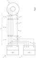
- Fig. 3 shows a circuit diagram of the connecting means 3 of an exemplary embodiment of a device for generating electrical energy, in particular a wind turbine with a generator 2 and a converter 4 or 4 '.
- the connecting means 3 between the generator 2 and the converter 4 or 4 ' are three-phase L1, L2, L3 or L1', L2', L3'.
- the generator 3 is also connected to the converter 4 or 4' via a neutral conductor N or N'.
- the neutral conductor N, N' is part of the machine-side connecting means 3.
- the connecting means 3 is divided into three areas A, B and C, with area B being designed, for example, as a busbar, for example in the tower of a wind turbine. Areas A and C should, for example, be designed as cables.
- Means for damping the series resonance of the connecting means 3 in the zero system 5, 6, 7, 8 and 9 are in Fig. 3 also shown, whereby the means shown for damping the series resonance 5, 6, 7, 8 and 9 are intended to illustrate in particular the different possible positions of the damping means.
- the means for damping the series resonance in the zero system 5, 6, 7, 8 and 9 are designed as series resistors that are magnetically coupled into the zero conductor N and through the annular magnetic core Fig. 3 symbolized.
- the means for damping the series resonance 5, 6, 7, 8 and 9 can be provided in areas A, B and C of the connecting means. If, for example, the neutral conductor N is implemented in area B by the metallic tower wall of a wind turbine, the magnetic coupling of the means for damping the series resonance cannot take place in this area. In this case it can also a different position for the magnetic coupling of a series resistor 5, 7, 8 or 9 can be used to dampen the series resonance, for example in the cable routed areas A and C.
- the cable-guided areas A and C of the connecting means 3 are preferably chosen for the magnetic coupling of the series resistance, since in these areas the magnetic coupling of the series resistance can be achieved in a simple manner with relatively small magnetic cores.
- the position of the means for damping the series resonance for example the position of the magnetic core for coupling in the series resistance, can be arranged in the different areas A, B or C of the multi-phase connecting means 3 depending on the circumstances. Since the neutral conductor N or N' is not designed to transmit large amounts of energy, it has smaller geometric dimensions than the other power phases. The arrangement of a magnetic core on the neutral conductor can therefore be done in a simple manner. In areas B and C, as already explained, this is particularly easy because the neutral conductor N or N 'is designed as a cable here. However, it is also conceivable that damping means are provided in several areas A, B and C.
- Figs. 4 and 5 now show a magnetic core made of soft magnetic solid material 10, preferably ferrite, which encloses a neutral conductor N and has at least one coil 11, which is connected or short-circuited via at least one series resistor 12. While Fig. 4 a sectional view perpendicular to the longitudinal axis of the neutral conductor N is shown in Fig. 5 a top view of the neutral conductor N is shown.
- the soft magnetic ring 10 encloses the neutral conductor N perpendicular to its longitudinal extent.
- the changing magnetic field induced in the magnetic core generates a voltage in the coil 11, which leads to a current flow across the series resistor 12.
- the magnetic core 10 which is made of soft magnetic solid material, in particular ferrite, has very little Heat losses occur due to the induction of alternating magnetic fields in the magnetic core, so that the heat loss in the soft magnetic, for example ferritic ring, remains low. Essentially the heat loss is then released in the series resistor 12 due to the damping of the series resonance.
- the in Figs. 4 and 5 The series resistance shown can preferably be set variably in its resistance value. This has the advantage that, for example, at the location where a wind turbine is installed, the series resistance can still be adjusted to optimize the damping of the series resonance after assembly. The same applies when retrofitting an existing device for generating electrical energy.
- FIG. 6 Another, simple way to magnetically couple a series resistance into the zero system is shown Fig. 6 in a schematic sectional view.
- a magnetic core 10' consisting of electrical sheet metal is shown here.
- the magnetic core has a defined gap so that a defined magnetic resistance can be set.
- the neutral conductor is also shown, which the magnetic core 10 'encloses.
- the magnetic core 10 'constructed in this way already provides the series resistance in which, during the change in the magnetization direction due to the series resonance, the magnetic resistance leads to heat loss and thus to a damping of the series resonance.
- the resulting heat loss is released throughout the entire magnetic core 10' and in this case must be sufficiently dissipated.
- the advantage of the laminated magnetic core 10' is that it is inexpensive and its geometric shape can be chosen relatively freely.
Landscapes
- Engineering & Computer Science (AREA)
- Power Engineering (AREA)
- Chemical & Material Sciences (AREA)
- Composite Materials (AREA)
- Dispersion Chemistry (AREA)
- Life Sciences & Earth Sciences (AREA)
- Sustainable Development (AREA)
- Sustainable Energy (AREA)
- Combustion & Propulsion (AREA)
- Mechanical Engineering (AREA)
- General Engineering & Computer Science (AREA)
- Control Of Eletrric Generators (AREA)
Claims (12)
- Un dispositif pour la production d'énergie électrique, en particulier une installation d'énergie éolienne (1), avec au moins un générateur (2), dans lequel le générateur (2) fournit d'énergie électrique via des moyens de connexion polyphasés, côté machine (3) et est relié électriquement à au moins un convertisseur (4, 4') avec circuit intermédiaire à tension continue via les moyens de connexion polyphasés, côté machine (3),
caractérisé en ce que
des moyens pour atténuer au moins une résonance en série (5, 6, 7, 8, 9) dans le système zéro des moyens de connexion côté machine (3) entre générateur (2) et convertisseur (4, 4') sont prévus. - Le dispositif selon la revendication 1,
caractérisé en ce que
les moyens pour atténuer la résonance en série dans le système zéro (5, 6, 7, 8, 9) présentent au moins une résistance en série (10', 12) introduit par couplage magnétique qui est effective pour le système zéro des moyens de connexion côté machine (3). - Le dispositif selon la revendication 1 ou 2,
caractérisé en ce que
l'au moins une résistance en série introduit par couplage magnétique (10', 12) dans le système zéro présente une résistance électrique R pour laquelle s'applique :

- Le dispositif selon l'une quelconque des revendications 1 à 3,
caractérisé en ce que
l'au moins une résistance en série introduit par couplage magnétique (10', 12) dans le système zéro des moyens de connexion côté machine (3) est introduit par couplage via au moins un noyau magnétique (10, 10'). - Le dispositif selon la revendication 4,
caractérisé en ce que
l'au moins un noyau magnétique (10', 11) enclot le conducteur neutre (N, N') des moyens de connexion côté machine (3) entre convertisseur (4, 4') et générateur (2) pour l'introduction par couplage magnétique de la résistance en série (10', 12). - Le dispositif selon l'une quelconque des revendications 4 et 5,
caractérisé en ce que
le conducteur neutre (N, N') des moyens de connexion côté machine (3) est réalisé au moins par zones sous forme de câble (A, C) et/ou de rail (B) et l'au moins un noyau magnétique (10, 10') est disposé au moins dans l'une de ces zones. - Le dispositif selon l'une quelconque des revendications 4 à 6,
caractérisé en ce que
l'au moins un noyau magnétique (10') présente fer doux, dans lequel facultativement un entrefer pour fournir une résistance magnétique spécifique du noyau magnétique (10') est prévu. - Le dispositif selon l'une quelconque des revendications 4 à 7,
caractérisé en ce que
l'au moins un noyau magnétique (10) est constitué d'un matériau plein magnétique doux, de préférence de ferrite, dans lequel l'au moins un noyau magnétique (10) présente au moins une bobine (11) dont les raccordements du bobinage sont reliées entre elles par au moins une résistance en série (12). - Le dispositif selon l'une quelconque des revendications 1 à 8,
caractérisé en ce que
l'au moins une résistance en série (12) est disposée sur des moyens de refroidissement et facultativement sa valeur de résistance peut être réglée de manière variable. - Le dispositif selon l'une quelconque des revendications 1 à 9,
caractérisé en ce que
les moyens de connexion côté machine (3) sont dimensionnés de manière à ce que la résonance en série des moyens de connexion (3) dans le système zéro apparaisse en dessous de 500 kHz, de préférence en dessous de 150 kHz. - Le dispositif selon l'une quelconque des revendications 1 à 10,
caractérisé en ce que
le dispositif est une installation d'énergie éolienne (1), dans lequel l'installation d'énergie éolienne présente comme générateur (2) une machine asynchrone à double alimentation ou un générateur synchrone. - Un procédé pour l'opération d'un dispositif pour la production d'énergie électrique, en particulier d'une installation d'énergie éolienne (1) selon l'une quelconque des revendications 1 à 11,
caractérisé en ce qu'
au moins une résonance en série dans le système zéro des moyens de connexion côté machine (3) entre générateur (2) et convertisseur (4, 4') est déterminée, une résistance en série (10', 12) pour atténuer cette résonance en série est spécifiée en fonction de la résonance en série déterminée, et cette résistance en série (10', 12) est introduit par couplage magnétique dans le système zéro.
Priority Applications (2)
| Application Number | Priority Date | Filing Date | Title |
|---|---|---|---|
| EP19169181.5A EP3726724B1 (fr) | 2019-04-15 | 2019-04-15 | Dispositif de production d'énergie électrique et procédé |
| US16/849,227 US20200328597A1 (en) | 2019-04-15 | 2020-04-15 | Device for generating electrical energy |
Applications Claiming Priority (1)
| Application Number | Priority Date | Filing Date | Title |
|---|---|---|---|
| EP19169181.5A EP3726724B1 (fr) | 2019-04-15 | 2019-04-15 | Dispositif de production d'énergie électrique et procédé |
Publications (2)
| Publication Number | Publication Date |
|---|---|
| EP3726724A1 EP3726724A1 (fr) | 2020-10-21 |
| EP3726724B1 true EP3726724B1 (fr) | 2023-12-13 |
Family
ID=66182385
Family Applications (1)
| Application Number | Title | Priority Date | Filing Date |
|---|---|---|---|
| EP19169181.5A Active EP3726724B1 (fr) | 2019-04-15 | 2019-04-15 | Dispositif de production d'énergie électrique et procédé |
Country Status (2)
| Country | Link |
|---|---|
| US (1) | US20200328597A1 (fr) |
| EP (1) | EP3726724B1 (fr) |
Families Citing this family (1)
| Publication number | Priority date | Publication date | Assignee | Title |
|---|---|---|---|---|
| DE102022200005A1 (de) * | 2022-01-03 | 2023-07-06 | Siemens Energy Global GmbH & Co. KG | Windkraftanlage und Verschaltung von Windkraftanlagen |
Family Cites Families (6)
| Publication number | Priority date | Publication date | Assignee | Title |
|---|---|---|---|---|
| DE10156694B4 (de) * | 2001-11-17 | 2005-10-13 | Semikron Elektronik Gmbh & Co. Kg | Schaltungsanordnung |
| JP4849545B2 (ja) * | 2006-02-02 | 2012-01-11 | Necトーキン株式会社 | 非晶質軟磁性合金、非晶質軟磁性合金部材、非晶質軟磁性合金薄帯、非晶質軟磁性合金粉末、及びそれを用いた磁芯ならびにインダクタンス部品 |
| DE102007048547A1 (de) * | 2006-10-20 | 2008-05-15 | Sekels Gmbh | Funkentstöranordnung |
| EP2390891A1 (fr) * | 2010-05-24 | 2011-11-30 | ABB Technology AG | Dispositif de suppression d'un transitoire très rapide |
| WO2014086363A2 (fr) | 2012-12-06 | 2014-06-12 | Vestas Wind Systems A/S | Système électrique à ca triphasé et procédé de compensation d'un déséquilibre d'inductance dans un tel système |
| US20150123402A1 (en) | 2013-11-04 | 2015-05-07 | General Electric Company | Magnetic structure combining normal mode and common mode inductance |
-
2019
- 2019-04-15 EP EP19169181.5A patent/EP3726724B1/fr active Active
-
2020
- 2020-04-15 US US16/849,227 patent/US20200328597A1/en not_active Abandoned
Also Published As
| Publication number | Publication date |
|---|---|
| US20200328597A1 (en) | 2020-10-15 |
| EP3726724A1 (fr) | 2020-10-21 |
Similar Documents
| Publication | Publication Date | Title |
|---|---|---|
| EP1118151B1 (fr) | Installation de transport d'energie electrique | |
| EP1311058B1 (fr) | Convertisseur de frequence | |
| EP0682402B1 (fr) | Dispositif pour la limitation de la pente des grandeurs de sortie d'un convertisseur auto-commuté à circuit intermédiaire à tension continue | |
| EP1220431A1 (fr) | Amortissement des surhaussements de résonance d'un moteur électrique alimenté par un convertisseur avec circuit intermédiaire de tension | |
| EP3785345B1 (fr) | Dispositif électronique de puissance à équipement de transformateur et procédé | |
| EP0682401A1 (fr) | Dispositif pour la limitation de la pente de la tension de sortie d'un convertisseur auto-commuté | |
| EP3726724B1 (fr) | Dispositif de production d'énergie électrique et procédé | |
| EP1211788A1 (fr) | Amortissement des surhaussements de résonance d'un moteur électrique alimenté par un convertisseur avec circuit intermédiaire de tension | |
| EP3036811B1 (fr) | Procédé et dispositif pour faire fonctionner un convertisseur dans un système de distribution d'énergie basé sur un onduleur et système de distribution d'énergie comprenant plusieurs unités de transmission d'énergie basées sur un onduleur | |
| WO2017016692A1 (fr) | Dispositif pour éviter les courants de palier dommageables | |
| WO2004064240A9 (fr) | Procede pour reduire les courants parasites en mode commun dans un systeme d'entrainement electrique, et systeme d'entrainement electrique correspondant | |
| EP3840207A1 (fr) | Connexion à faible inductance des agencements de convertisseur spatialement séparés | |
| EP1217712A2 (fr) | Atténuation de résonances amplifiées dans un moteur alimenté par convertisseur à tension constante par amplification des pertes dans le domaine des fréquences de résonance | |
| EP3393028B1 (fr) | Éolienne pourvue de système convertisseur permettant de réduire le rayonnement em | |
| EP3179617B1 (fr) | Circuit de compensation d'une partie de courant continu dans un transformateur | |
| EP2572445B1 (fr) | Convertisseur à puissance et fréquence modulables | |
| EP4033646A1 (fr) | Procédé et dispositif de réduction d'harmoniques de courant | |
| DE10064213A1 (de) | Frequenzumrichtersystem mit einer Dämpfungseinrichtung mit einer passiven, statischen Impedanz zur Bedämpfung unerwünschter Resonanzschwingungen in einem durch mindestens eine eingangsseitige Induktivität und parasitäre verteilte Kapazitäten gebildeten Schwingkreis | |
| EP3637606A1 (fr) | Système d'entraînement comprenant une pluralité de convertisseurs | |
| DE102018006788A1 (de) | Windenergieanlage mit verbessertem Störverhalten | |
| DE19952886A1 (de) | Mehrfachstromrichter | |
| EP3721521B1 (fr) | Moyen transformateur pour la transmission d'ondes harmoniques | |
| DE19861015A9 (de) | Anordnung zur Einspeisung von elektrischem Strom in ein 3-phasiges Stromnetz | |
| EP3446320B1 (fr) | Bobine d'inductance triphasée | |
| WO2025124937A1 (fr) | Convertisseur de puissance ayant de multiples modules convertisseurs |
Legal Events
| Date | Code | Title | Description |
|---|---|---|---|
| PUAI | Public reference made under article 153(3) epc to a published international application that has entered the european phase |
Free format text: ORIGINAL CODE: 0009012 |
|
| STAA | Information on the status of an ep patent application or granted ep patent |
Free format text: STATUS: THE APPLICATION HAS BEEN PUBLISHED |
|
| AK | Designated contracting states |
Kind code of ref document: A1 Designated state(s): AL AT BE BG CH CY CZ DE DK EE ES FI FR GB GR HR HU IE IS IT LI LT LU LV MC MK MT NL NO PL PT RO RS SE SI SK SM TR |
|
| RAP1 | Party data changed (applicant data changed or rights of an application transferred) |
Owner name: CONVERTERTEC DEUTSCHLAND GMBH |
|
| STAA | Information on the status of an ep patent application or granted ep patent |
Free format text: STATUS: REQUEST FOR EXAMINATION WAS MADE |
|
| 17P | Request for examination filed |
Effective date: 20210421 |
|
| RBV | Designated contracting states (corrected) |
Designated state(s): AL AT BE BG CH CY CZ DE DK EE ES FI FR GB GR HR HU IE IS IT LI LT LU LV MC MK MT NL NO PL PT RO RS SE SI SK SM TR |
|
| STAA | Information on the status of an ep patent application or granted ep patent |
Free format text: STATUS: EXAMINATION IS IN PROGRESS |
|
| 17Q | First examination report despatched |
Effective date: 20220314 |
|
| GRAP | Despatch of communication of intention to grant a patent |
Free format text: ORIGINAL CODE: EPIDOSNIGR1 |
|
| STAA | Information on the status of an ep patent application or granted ep patent |
Free format text: STATUS: GRANT OF PATENT IS INTENDED |
|
| INTG | Intention to grant announced |
Effective date: 20230704 |
|
| GRAS | Grant fee paid |
Free format text: ORIGINAL CODE: EPIDOSNIGR3 |
|
| GRAA | (expected) grant |
Free format text: ORIGINAL CODE: 0009210 |
|
| STAA | Information on the status of an ep patent application or granted ep patent |
Free format text: STATUS: THE PATENT HAS BEEN GRANTED |
|
| AK | Designated contracting states |
Kind code of ref document: B1 Designated state(s): AL AT BE BG CH CY CZ DE DK EE ES FI FR GB GR HR HU IE IS IT LI LT LU LV MC MK MT NL NO PL PT RO RS SE SI SK SM TR |
|
| REG | Reference to a national code |
Ref country code: GB Ref legal event code: FG4D Free format text: NOT ENGLISH |
|
| REG | Reference to a national code |
Ref country code: CH Ref legal event code: EP |
|
| REG | Reference to a national code |
Ref country code: DE Ref legal event code: R096 Ref document number: 502019010116 Country of ref document: DE |
|
| REG | Reference to a national code |
Ref country code: IE Ref legal event code: FG4D Free format text: LANGUAGE OF EP DOCUMENT: GERMAN |
|
| RAP2 | Party data changed (patent owner data changed or rights of a patent transferred) |
Owner name: KK WIND SOLUTIONS A/S |
|
| REG | Reference to a national code |
Ref country code: DE Ref legal event code: R081 Ref document number: 502019010116 Country of ref document: DE Owner name: KK WIND SOLUTIONS A/S, DK Free format text: FORMER OWNER: CONVERTERTEC DEUTSCHLAND GMBH, 47906 KEMPEN, DE |
|
| PG25 | Lapsed in a contracting state [announced via postgrant information from national office to epo] |
Ref country code: GR Free format text: LAPSE BECAUSE OF FAILURE TO SUBMIT A TRANSLATION OF THE DESCRIPTION OR TO PAY THE FEE WITHIN THE PRESCRIBED TIME-LIMIT Effective date: 20240314 |
|
| REG | Reference to a national code |
Ref country code: LT Ref legal event code: MG9D |
|
| PG25 | Lapsed in a contracting state [announced via postgrant information from national office to epo] |
Ref country code: LT Free format text: LAPSE BECAUSE OF FAILURE TO SUBMIT A TRANSLATION OF THE DESCRIPTION OR TO PAY THE FEE WITHIN THE PRESCRIBED TIME-LIMIT Effective date: 20231213 |
|
| REG | Reference to a national code |
Ref country code: NL Ref legal event code: MP Effective date: 20231213 |
|
| PG25 | Lapsed in a contracting state [announced via postgrant information from national office to epo] |
Ref country code: ES Free format text: LAPSE BECAUSE OF FAILURE TO SUBMIT A TRANSLATION OF THE DESCRIPTION OR TO PAY THE FEE WITHIN THE PRESCRIBED TIME-LIMIT Effective date: 20231213 |
|
| PG25 | Lapsed in a contracting state [announced via postgrant information from national office to epo] |
Ref country code: LT Free format text: LAPSE BECAUSE OF FAILURE TO SUBMIT A TRANSLATION OF THE DESCRIPTION OR TO PAY THE FEE WITHIN THE PRESCRIBED TIME-LIMIT Effective date: 20231213 Ref country code: GR Free format text: LAPSE BECAUSE OF FAILURE TO SUBMIT A TRANSLATION OF THE DESCRIPTION OR TO PAY THE FEE WITHIN THE PRESCRIBED TIME-LIMIT Effective date: 20240314 Ref country code: ES Free format text: LAPSE BECAUSE OF FAILURE TO SUBMIT A TRANSLATION OF THE DESCRIPTION OR TO PAY THE FEE WITHIN THE PRESCRIBED TIME-LIMIT Effective date: 20231213 Ref country code: BG Free format text: LAPSE BECAUSE OF FAILURE TO SUBMIT A TRANSLATION OF THE DESCRIPTION OR TO PAY THE FEE WITHIN THE PRESCRIBED TIME-LIMIT Effective date: 20240313 |
|
| PG25 | Lapsed in a contracting state [announced via postgrant information from national office to epo] |
Ref country code: NL Free format text: LAPSE BECAUSE OF FAILURE TO SUBMIT A TRANSLATION OF THE DESCRIPTION OR TO PAY THE FEE WITHIN THE PRESCRIBED TIME-LIMIT Effective date: 20231213 |
|
| PG25 | Lapsed in a contracting state [announced via postgrant information from national office to epo] |
Ref country code: SE Free format text: LAPSE BECAUSE OF FAILURE TO SUBMIT A TRANSLATION OF THE DESCRIPTION OR TO PAY THE FEE WITHIN THE PRESCRIBED TIME-LIMIT Effective date: 20231213 Ref country code: RS Free format text: LAPSE BECAUSE OF FAILURE TO SUBMIT A TRANSLATION OF THE DESCRIPTION OR TO PAY THE FEE WITHIN THE PRESCRIBED TIME-LIMIT Effective date: 20231213 Ref country code: NO Free format text: LAPSE BECAUSE OF FAILURE TO SUBMIT A TRANSLATION OF THE DESCRIPTION OR TO PAY THE FEE WITHIN THE PRESCRIBED TIME-LIMIT Effective date: 20240313 Ref country code: NL Free format text: LAPSE BECAUSE OF FAILURE TO SUBMIT A TRANSLATION OF THE DESCRIPTION OR TO PAY THE FEE WITHIN THE PRESCRIBED TIME-LIMIT Effective date: 20231213 Ref country code: LV Free format text: LAPSE BECAUSE OF FAILURE TO SUBMIT A TRANSLATION OF THE DESCRIPTION OR TO PAY THE FEE WITHIN THE PRESCRIBED TIME-LIMIT Effective date: 20231213 Ref country code: HR Free format text: LAPSE BECAUSE OF FAILURE TO SUBMIT A TRANSLATION OF THE DESCRIPTION OR TO PAY THE FEE WITHIN THE PRESCRIBED TIME-LIMIT Effective date: 20231213 |
|
| PG25 | Lapsed in a contracting state [announced via postgrant information from national office to epo] |
Ref country code: IS Free format text: LAPSE BECAUSE OF FAILURE TO SUBMIT A TRANSLATION OF THE DESCRIPTION OR TO PAY THE FEE WITHIN THE PRESCRIBED TIME-LIMIT Effective date: 20240413 |
|
| PG25 | Lapsed in a contracting state [announced via postgrant information from national office to epo] |
Ref country code: CZ Free format text: LAPSE BECAUSE OF FAILURE TO SUBMIT A TRANSLATION OF THE DESCRIPTION OR TO PAY THE FEE WITHIN THE PRESCRIBED TIME-LIMIT Effective date: 20231213 |
|
| PG25 | Lapsed in a contracting state [announced via postgrant information from national office to epo] |
Ref country code: SK Free format text: LAPSE BECAUSE OF FAILURE TO SUBMIT A TRANSLATION OF THE DESCRIPTION OR TO PAY THE FEE WITHIN THE PRESCRIBED TIME-LIMIT Effective date: 20231213 |
|
| PG25 | Lapsed in a contracting state [announced via postgrant information from national office to epo] |
Ref country code: SM Free format text: LAPSE BECAUSE OF FAILURE TO SUBMIT A TRANSLATION OF THE DESCRIPTION OR TO PAY THE FEE WITHIN THE PRESCRIBED TIME-LIMIT Effective date: 20231213 Ref country code: SK Free format text: LAPSE BECAUSE OF FAILURE TO SUBMIT A TRANSLATION OF THE DESCRIPTION OR TO PAY THE FEE WITHIN THE PRESCRIBED TIME-LIMIT Effective date: 20231213 Ref country code: RO Free format text: LAPSE BECAUSE OF FAILURE TO SUBMIT A TRANSLATION OF THE DESCRIPTION OR TO PAY THE FEE WITHIN THE PRESCRIBED TIME-LIMIT Effective date: 20231213 Ref country code: IT Free format text: LAPSE BECAUSE OF FAILURE TO SUBMIT A TRANSLATION OF THE DESCRIPTION OR TO PAY THE FEE WITHIN THE PRESCRIBED TIME-LIMIT Effective date: 20231213 Ref country code: IS Free format text: LAPSE BECAUSE OF FAILURE TO SUBMIT A TRANSLATION OF THE DESCRIPTION OR TO PAY THE FEE WITHIN THE PRESCRIBED TIME-LIMIT Effective date: 20240413 Ref country code: EE Free format text: LAPSE BECAUSE OF FAILURE TO SUBMIT A TRANSLATION OF THE DESCRIPTION OR TO PAY THE FEE WITHIN THE PRESCRIBED TIME-LIMIT Effective date: 20231213 Ref country code: CZ Free format text: LAPSE BECAUSE OF FAILURE TO SUBMIT A TRANSLATION OF THE DESCRIPTION OR TO PAY THE FEE WITHIN THE PRESCRIBED TIME-LIMIT Effective date: 20231213 |
|
| PG25 | Lapsed in a contracting state [announced via postgrant information from national office to epo] |
Ref country code: PL Free format text: LAPSE BECAUSE OF FAILURE TO SUBMIT A TRANSLATION OF THE DESCRIPTION OR TO PAY THE FEE WITHIN THE PRESCRIBED TIME-LIMIT Effective date: 20231213 Ref country code: PT Free format text: LAPSE BECAUSE OF FAILURE TO SUBMIT A TRANSLATION OF THE DESCRIPTION OR TO PAY THE FEE WITHIN THE PRESCRIBED TIME-LIMIT Effective date: 20240415 |
|
| PG25 | Lapsed in a contracting state [announced via postgrant information from national office to epo] |
Ref country code: PT Free format text: LAPSE BECAUSE OF FAILURE TO SUBMIT A TRANSLATION OF THE DESCRIPTION OR TO PAY THE FEE WITHIN THE PRESCRIBED TIME-LIMIT Effective date: 20240415 Ref country code: PL Free format text: LAPSE BECAUSE OF FAILURE TO SUBMIT A TRANSLATION OF THE DESCRIPTION OR TO PAY THE FEE WITHIN THE PRESCRIBED TIME-LIMIT Effective date: 20231213 |
|
| REG | Reference to a national code |
Ref country code: DE Ref legal event code: R097 Ref document number: 502019010116 Country of ref document: DE |
|
| PG25 | Lapsed in a contracting state [announced via postgrant information from national office to epo] |
Ref country code: DK Free format text: LAPSE BECAUSE OF FAILURE TO SUBMIT A TRANSLATION OF THE DESCRIPTION OR TO PAY THE FEE WITHIN THE PRESCRIBED TIME-LIMIT Effective date: 20231213 |
|
| PLBE | No opposition filed within time limit |
Free format text: ORIGINAL CODE: 0009261 |
|
| STAA | Information on the status of an ep patent application or granted ep patent |
Free format text: STATUS: NO OPPOSITION FILED WITHIN TIME LIMIT |
|
| PG25 | Lapsed in a contracting state [announced via postgrant information from national office to epo] |
Ref country code: SI Free format text: LAPSE BECAUSE OF FAILURE TO SUBMIT A TRANSLATION OF THE DESCRIPTION OR TO PAY THE FEE WITHIN THE PRESCRIBED TIME-LIMIT Effective date: 20231213 |
|
| PG25 | Lapsed in a contracting state [announced via postgrant information from national office to epo] |
Ref country code: SI Free format text: LAPSE BECAUSE OF FAILURE TO SUBMIT A TRANSLATION OF THE DESCRIPTION OR TO PAY THE FEE WITHIN THE PRESCRIBED TIME-LIMIT Effective date: 20231213 Ref country code: DK Free format text: LAPSE BECAUSE OF FAILURE TO SUBMIT A TRANSLATION OF THE DESCRIPTION OR TO PAY THE FEE WITHIN THE PRESCRIBED TIME-LIMIT Effective date: 20231213 |
|
| 26N | No opposition filed |
Effective date: 20240916 |
|
| PG25 | Lapsed in a contracting state [announced via postgrant information from national office to epo] |
Ref country code: MC Free format text: LAPSE BECAUSE OF FAILURE TO SUBMIT A TRANSLATION OF THE DESCRIPTION OR TO PAY THE FEE WITHIN THE PRESCRIBED TIME-LIMIT Effective date: 20231213 |
|
| PG25 | Lapsed in a contracting state [announced via postgrant information from national office to epo] |
Ref country code: MC Free format text: LAPSE BECAUSE OF FAILURE TO SUBMIT A TRANSLATION OF THE DESCRIPTION OR TO PAY THE FEE WITHIN THE PRESCRIBED TIME-LIMIT Effective date: 20231213 |
|
| REG | Reference to a national code |
Ref country code: CH Ref legal event code: PL |
|
| PG25 | Lapsed in a contracting state [announced via postgrant information from national office to epo] |
Ref country code: LU Free format text: LAPSE BECAUSE OF NON-PAYMENT OF DUE FEES Effective date: 20240415 |
|
| REG | Reference to a national code |
Ref country code: BE Ref legal event code: MM Effective date: 20240430 |
|
| PG25 | Lapsed in a contracting state [announced via postgrant information from national office to epo] |
Ref country code: LU Free format text: LAPSE BECAUSE OF NON-PAYMENT OF DUE FEES Effective date: 20240415 |
|
| PG25 | Lapsed in a contracting state [announced via postgrant information from national office to epo] |
Ref country code: BE Free format text: LAPSE BECAUSE OF NON-PAYMENT OF DUE FEES Effective date: 20240430 |
|
| PG25 | Lapsed in a contracting state [announced via postgrant information from national office to epo] |
Ref country code: BE Free format text: LAPSE BECAUSE OF NON-PAYMENT OF DUE FEES Effective date: 20240430 Ref country code: CH Free format text: LAPSE BECAUSE OF NON-PAYMENT OF DUE FEES Effective date: 20240430 |
|
| PG25 | Lapsed in a contracting state [announced via postgrant information from national office to epo] |
Ref country code: IE Free format text: LAPSE BECAUSE OF NON-PAYMENT OF DUE FEES Effective date: 20240415 |
|
| REG | Reference to a national code |
Ref country code: AT Ref legal event code: MM01 Ref document number: 1641331 Country of ref document: AT Kind code of ref document: T Effective date: 20240415 |
|
| PGFP | Annual fee paid to national office [announced via postgrant information from national office to epo] |
Ref country code: DE Payment date: 20250417 Year of fee payment: 7 |
|
| PGFP | Annual fee paid to national office [announced via postgrant information from national office to epo] |
Ref country code: FR Payment date: 20250422 Year of fee payment: 7 |
|
| PG25 | Lapsed in a contracting state [announced via postgrant information from national office to epo] |
Ref country code: AT Free format text: LAPSE BECAUSE OF NON-PAYMENT OF DUE FEES Effective date: 20240415 |
|
| PG25 | Lapsed in a contracting state [announced via postgrant information from national office to epo] |
Ref country code: CY Free format text: LAPSE BECAUSE OF FAILURE TO SUBMIT A TRANSLATION OF THE DESCRIPTION OR TO PAY THE FEE WITHIN THE PRESCRIBED TIME-LIMIT; INVALID AB INITIO Effective date: 20190415 |
|
| PG25 | Lapsed in a contracting state [announced via postgrant information from national office to epo] |
Ref country code: HU Free format text: LAPSE BECAUSE OF FAILURE TO SUBMIT A TRANSLATION OF THE DESCRIPTION OR TO PAY THE FEE WITHIN THE PRESCRIBED TIME-LIMIT; INVALID AB INITIO Effective date: 20190415 |
|
| PG25 | Lapsed in a contracting state [announced via postgrant information from national office to epo] |
Ref country code: FI Free format text: LAPSE BECAUSE OF FAILURE TO SUBMIT A TRANSLATION OF THE DESCRIPTION OR TO PAY THE FEE WITHIN THE PRESCRIBED TIME-LIMIT Effective date: 20231213 |
|
| PGFP | Annual fee paid to national office [announced via postgrant information from national office to epo] |
Ref country code: GB Payment date: 20260324 Year of fee payment: 8 |