EP3726853B1 - Procédé de traitement directionnel du signal pour un appareil auditif - Google Patents
Procédé de traitement directionnel du signal pour un appareil auditif Download PDFInfo
- Publication number
- EP3726853B1 EP3726853B1 EP20155945.7A EP20155945A EP3726853B1 EP 3726853 B1 EP3726853 B1 EP 3726853B1 EP 20155945 A EP20155945 A EP 20155945A EP 3726853 B1 EP3726853 B1 EP 3726853B1
- Authority
- EP
- European Patent Office
- Prior art keywords
- signal
- directional
- basis
- generated
- input
- Prior art date
- Legal status (The legal status is an assumption and is not a legal conclusion. Google has not performed a legal analysis and makes no representation as to the accuracy of the status listed.)
- Active
Links
Images


Classifications
-
- H—ELECTRICITY
- H04—ELECTRIC COMMUNICATION TECHNIQUE
- H04R—LOUDSPEAKERS, MICROPHONES, GRAMOPHONE PICK-UPS OR LIKE ACOUSTIC ELECTROMECHANICAL TRANSDUCERS; ELECTRIC HEARING AIDS; PUBLIC ADDRESS SYSTEMS
- H04R3/00—Circuits for transducers
-
- H—ELECTRICITY
- H04—ELECTRIC COMMUNICATION TECHNIQUE
- H04R—LOUDSPEAKERS, MICROPHONES, GRAMOPHONE PICK-UPS OR LIKE ACOUSTIC ELECTROMECHANICAL TRANSDUCERS; ELECTRIC HEARING AIDS; PUBLIC ADDRESS SYSTEMS
- H04R25/00—Electric hearing aids
- H04R25/40—Arrangements for obtaining a desired directivity characteristic
- H04R25/407—Circuits for combining signals of a plurality of transducers
-
- H—ELECTRICITY
- H04—ELECTRIC COMMUNICATION TECHNIQUE
- H04R—LOUDSPEAKERS, MICROPHONES, GRAMOPHONE PICK-UPS OR LIKE ACOUSTIC ELECTROMECHANICAL TRANSDUCERS; ELECTRIC HEARING AIDS; PUBLIC ADDRESS SYSTEMS
- H04R25/00—Electric hearing aids
- H04R25/35—Electric hearing aids using translation techniques
- H04R25/356—Amplitude, e.g. amplitude shift or compression
-
- H—ELECTRICITY
- H04—ELECTRIC COMMUNICATION TECHNIQUE
- H04R—LOUDSPEAKERS, MICROPHONES, GRAMOPHONE PICK-UPS OR LIKE ACOUSTIC ELECTROMECHANICAL TRANSDUCERS; ELECTRIC HEARING AIDS; PUBLIC ADDRESS SYSTEMS
- H04R25/00—Electric hearing aids
- H04R25/40—Arrangements for obtaining a desired directivity characteristic
- H04R25/405—Arrangements for obtaining a desired directivity characteristic by combining a plurality of transducers
-
- H—ELECTRICITY
- H04—ELECTRIC COMMUNICATION TECHNIQUE
- H04R—LOUDSPEAKERS, MICROPHONES, GRAMOPHONE PICK-UPS OR LIKE ACOUSTIC ELECTROMECHANICAL TRANSDUCERS; ELECTRIC HEARING AIDS; PUBLIC ADDRESS SYSTEMS
- H04R3/00—Circuits for transducers
- H04R3/04—Circuits for transducers for correcting frequency response
-
- H—ELECTRICITY
- H04—ELECTRIC COMMUNICATION TECHNIQUE
- H04R—LOUDSPEAKERS, MICROPHONES, GRAMOPHONE PICK-UPS OR LIKE ACOUSTIC ELECTROMECHANICAL TRANSDUCERS; ELECTRIC HEARING AIDS; PUBLIC ADDRESS SYSTEMS
- H04R2225/00—Details of deaf aids covered by H04R25/00, not provided for in any of its subgroups
- H04R2225/43—Signal processing in hearing aids to enhance the speech intelligibility
-
- H—ELECTRICITY
- H04—ELECTRIC COMMUNICATION TECHNIQUE
- H04R—LOUDSPEAKERS, MICROPHONES, GRAMOPHONE PICK-UPS OR LIKE ACOUSTIC ELECTROMECHANICAL TRANSDUCERS; ELECTRIC HEARING AIDS; PUBLIC ADDRESS SYSTEMS
- H04R2430/00—Signal processing covered by H04R, not provided for in its groups
- H04R2430/01—Aspects of volume control, not necessarily automatic, in sound systems
-
- H—ELECTRICITY
- H04—ELECTRIC COMMUNICATION TECHNIQUE
- H04R—LOUDSPEAKERS, MICROPHONES, GRAMOPHONE PICK-UPS OR LIKE ACOUSTIC ELECTROMECHANICAL TRANSDUCERS; ELECTRIC HEARING AIDS; PUBLIC ADDRESS SYSTEMS
- H04R2430/00—Signal processing covered by H04R, not provided for in its groups
- H04R2430/20—Processing of the output signals of the acoustic transducers of an array for obtaining a desired directivity characteristic
- H04R2430/23—Direction finding using a sum-delay beam-former
Definitions
- ambient sound is converted into an input signal by means of at least one input transducer, which is processed and amplified in a frequency band-specific manner depending on the hearing impairment of the wearer that is to be corrected, and in particular individually tailored to the wearer.
- the processed signal is converted into an output sound signal via an output transducer of the hearing aid, which is fed to the wearer's ear.
- an automatic volume control (“automatic gain control", AGC) and also a dynamic compression are often applied to the input signal or to an already pre-processed intermediate signal, in which the input signal is usually only linearly amplified up to a certain limit, and above the limit a lower amplification is used to compensate for peak levels in the input signal. This is intended in particular to prevent sudden, loud sound events from leading to an output sound signal that is too loud for the wearer due to the additional amplification in the hearing aid.
- AGC automatic volume control
- dynamic compression are often applied to the input signal or to an already pre-processed intermediate signal, in which the input signal is usually only linear
- the EP 3 337 188 A1 mentions a method for operating a hearing aid which comprises at least a first input transducer, a second input transducer and at least one output transducer, wherein the first input transducer generates a first input signal from a sound signal from the environment and the second input transducer generates a second input signal from the sound signal, wherein a first direction is assigned to a first useful signal source and a second useful signal source which is spatially separated from the first useful signal source is assigned a second direction, wherein a first directional signal oriented in the first direction and a second directional signal oriented in the second direction are formed on the basis of the first input signal and the second input signal, and wherein an output signal is formed on the basis of the first directional signal and the second directional signal, which is converted into a sound signal by the output transducer of the hearing aid.
- the EP 3 104 627 A1 mentions a method for improving a recording signal in a hearing system with at least one hearing aid, wherein the hearing aid is assigned a first directional microphone which has an adjustable first directional characteristic with a preferred direction, wherein the first directional microphone converts sound into a first signal which is included in the recording signal, wherein depending on a speech activity of a user (1) of the hearing system (2), the The preferred direction of the first directional characteristic is adjusted relative to a frontal direction of the user in such a way that the sound sensitivity of the first directional microphone is attenuated in the frontal direction.
- Two output signals of a microphone system depend differently on the angle of incidence of the acoustic signals, and are divided by each other.
- a mathematical product of the ratio and a weighting factor is saturated and subtracted from a signal value that can be fed into the system.
- the subtraction remainder is multiplied by the output signal of the microphone system, which also generates the denominator signal for the division.
- a desired directional characteristic is implemented between the resulting signal of the multiplication and the angle of incidence of acoustic signals acting on the microphone system.
- the invention is based on the object of specifying a method for signal processing in a hearing aid which, in particular in conjunction with AGC and dynamic compression, is also suitable for complex hearing situations.
- a first input signal is generated from a sound signal from the environment by a first input transducer of the hearing aid
- a second input signal is generated from the sound signal from the environment by a second input transducer of the hearing aid
- a first calibration directional signal is generated based on the first input signal and the second input signal, which has a maximum attenuation in the direction of a first useful signal source in the environment
- a second calibration directional signal is generated based on the first input signal and the second input signal, which has a maximum attenuation in the direction of a second useful signal source in the environment
- a relative gain parameter is determined based on the first calibration directional signal and the second calibration directional signal
- a first instantaneous gain parameter is determined based on the first calibration directional signal is determined, wherein a second instantaneous gain parameter is determined based on the second
- a first processing directional signal and a second processing directional signal are generated based on both the first input signal and the second input signal, wherein a source-sensitive directional signal is generated based on the first processing directional signal, the second processing directional signal and the relative gain parameter, and wherein an output signal of the hearing aid is generated based on the source-sensitive directional signal, which is preferably converted into an output sound signal by an output transducer of the hearing aid, wherein a derived signal strength in the direction of the first useful signal source is determined based on the relative gain parameter and the reference signal strength, and wherein a complex superposition parameter for superimposing the first processing directional signal with the second processing directional signal is determined based on the derived signal strength, and the source-sensitive directional signal is generated based on the associated superposition.
- An input transducer here includes in particular an electroacoustic transducer which is designed to generate a corresponding electrical signal from a sound signal.
- preprocessing can also take place, e.g. in the form of linear preamplification and/or A/D conversion.
- the generation based on the first or the second calibration directional signal based on the first and the second input signal preferably comprises that the signal components of the first and the second input signal are directly incorporated into the respective calibration directional signal, and thus in particular the first and the second input signal is not both used simultaneously only for generating control parameters or similar, which are applied to signal components of other signals.
- the signal components of the first input signal, and particularly preferably also the signal components of the second input signal are linearly incorporated into the first calibration directional signal. The same preferably also applies to the second calibration directional signal.
- the first and second calibration directional signals can be formed in particular using intermediate signals, which are each generated using the first and second input signals.
- a directional first intermediate signal can be formed using the first and second input signals, and also a directional second intermediate signal, with the directional characteristics of the first and second intermediate signals preferably being symmetrical to one another, e.g. as cardioid and anti-cardioid.
- the first calibration directional signal can then be generated using adaptive directional microphony from the first and second intermediate signals in such a way that the adaptive directional microphony, as required, results in a relative attenuation in the direction of the first useful signal source.
- the relative gain parameter is preferably to be generated on the basis of the first and the second calibration directional signal in such a way that, with a corresponding superposition of the signal components of the first and the second calibration directional signal, weighted with the relative gain parameter, an output signal resulting from such a superposition can be controlled as far as possible via a common AGC and in particular via a common dynamic compression, and for this purpose the signal components arriving from at least two directions are taken into account and weighted as optimally as possible.
- the relative gain parameter can then be used in particular for superimposing the first processing directional signal with the second processing directional signal.
- the first and second processing directional signals are generated using the same intermediate signals as the first and the second calibration directional signal.
- a further, preferably common degree of freedom e.g. in the form of an additional adaptation parameter or similar, which is not present in the calibration directional signals, can be added to both the first and the second intermediate signal when generating the processing directional signals.
- Such an additional degree of freedom makes it possible to adjust the sensitivity of the directional characteristic of the source-sensitive directional signal in the direction of both the first and the second useful signal source by varying the said adaptation parameter, in particular depending on the relative gain parameter, which enables subsequent treatment of the source-sensitive directional signal or the output signal generated therefrom via an AGC and a corresponding dynamic compression in a manner that takes into account the two useful signals of the said useful signal sources.
- the degree of freedom required for this purpose can also be introduced into a superposition of the two processing directional signals, e.g. in the form of a complex-valued superposition parameter when generating the source-sensitive directional signal.
- the first and second calibration directional signals are preferably determined in such a way that the sound events of a useful signal source (such as speech contributions from one conversation partner) are emphasized as much as possible and the sound events of another useful signal source (e.g. speech contributions from another conversation partner) are suppressed as much as possible, whereby the roles of the sound events to be suppressed and emphasized are swapped for the two calibration directional signals.
- a useful signal source such as speech contributions from one conversation partner
- another useful signal source e.g. speech contributions from another conversation partner
- the relative gain parameter is preferably determined in such a way that a corresponding superposition of the two calibration directional signals - for example a superposition of the first Calibration directional signal with the second calibration directional signal, which is weighted with the relative gain parameter - can be controlled by a common AGC value as a result of the described suppressions and emphasis of the respective sound events, whereby excessive influences of one sound event by the other sound event can be avoided in the superimposed signal.
- the source-sensitive directional signal from which the output signal is generated by additional signal processing if necessary, is not generated by superimposing the two calibration directional signals, but rather by using the two processing directional signals. This is done because superimposing the two calibration directional signals for further processing could lead to the direction of maximum attenuation of the superimposed signal fluctuating in a wider angular range of up to 90° depending on the sound events of the useful signal sources, as can occur, for example, with adaptive directional microphones. In particular, this direction no longer coincides with the direction of one of the useful signal sources.
- an additional degree of freedom can now be introduced via the two processing directional signals depending on the relative gain parameter determined using the calibration directional signals, whereby the direction of the maximum attenuation can be stabilized in the source-sensitive directional signal.
- a sudden change in the sound of a wanted signal source now leads, via a corresponding change in the relative gain parameter and a resulting different weighting of the two processing directional signals, to the signal contributions of the other wanted signal source in the source-sensitive directional signal not being affected or only minimally affected by this change in an AGC with dynamic compression.
- a third input signal can be generated by a third input transducer of the hearing aid, so that a total of three calibration directional signals are generated on the basis of the existing input signals, each of which has a relative attenuation in the direction of a different one of three useful signal sources.
- Two relative gain parameters can then be determined from the three calibration directional signals, so that three processing directional signals, which in turn are generated from the three input signals, are superimposed on the two relative gain parameters.
- the method can be extended to even higher order systems in the input transducers.
- a first instantaneous gain parameter is determined based on the first calibration directional signal and a second instantaneous gain parameter is determined based on the second calibration directional signal, the relative gain parameter being determined based on the first instantaneous gain parameter and the second instantaneous gain parameter, in particular as a quotient thereof.
- the first instantaneous gain parameter and the second instantaneous gain parameter are preferably determined as "isolated" values of an AGC or a dynamic compression for the respective calibration directional signal.
- a first intermediate signal and a second intermediate signal are expediently generated from both the first input signal and the second input signal. This makes it possible to generate the calibration directional signals and/or the processing directional signals using adaptive directional microphones, the intermediate signals being used in the adaptive directional microphones.
- the first calibration directional signal is generated by means of adaptive directional microphones, in particular based on the first and second intermediate signals
- the second calibration directional signal is generated by means of adaptive directional microphones, in particular based on the first and second intermediate signals.
- the first intermediate signal is generated using a time-delayed superposition of the first input signal with the second input signal, implemented using a first delay parameter
- the second intermediate signal is generated using a time-delayed superposition of the second input signal with the first input signal, implemented using a second delay parameter.
- the first and second delay parameters can be selected to be identical to one another, and in particular the first intermediate signal can be generated symmetrically to the second intermediate signal with respect to a preferred plane of the hearing aid, wherein the preferred plane is preferably assigned to the frontal plane of the wearer when wearing the hearing aid. Aligning the directional signals with the frontal direction of the wearer facilitates signal processing, as this takes the wearer's natural viewing direction into account.
- the first intermediate signal is generated as a forward-directed cardioid directional signal and/or the second intermediate signal as a backward-directed cardioid directional signal.
- a cardioid directional signal can be formed by superimposing the two input signals on each other with the acoustic propagation delay corresponding to the distance between the input transducers. This Depending on the sign of this delay during superposition, the direction of maximum attenuation is in the frontal direction (backward-directed cardioid directional signal) or in the opposite direction (forward-directed cardioid directional signal). The direction of maximum sensitivity is opposite to the direction of maximum attenuation. This facilitates further signal processing, since such an intermediate signal is particularly suitable for adaptive directional microphony.
- the first calibration directional signal and the second calibration directional signal are both generated based on both the first intermediate signal and the second intermediate signal.
- the first processing directional signal is generated from the first intermediate signal, and in particular "identical” to it, and/or the second processing directional signal is generated from the second intermediate signal, in particular "identical” to it.
- Generating the first or second processing directional signal from the first or second intermediate signal is to be understood here (and analogously below) in particular to mean that no signal components of other signals are included in the generated signal other than the signal components of the said "generating" signal. Signal components of other signals are used at most as control signals for parameters when generating the respective processing directional signal.
- the first processing directional signal is generated identically to the first intermediate signal by reusing the first intermediate signal for the subsequent method steps as the first processing directional signal. In order to reduce complexity, it is advantageous if both the calibration directional signals and the processing directional signals are based on the same intermediate signals.
- the first processing directional signal is formed as a first asymmetrical superposition signal based on a time-delayed superposition of the first input signal with the second input signal implemented by means of asymmetrical first weighting factors. and/or the second processing directional signal is formed as a second asymmetrical superposition signal based on a time-delayed superposition of the second input signal with the first input signal, implemented by means of asymmetrical second weighting factors.
- the first input signal E1 is superimposed on the second input signal E2 according to E1 - w1 E2, whereby the weighting of the two input signals is not identical, but is measured based on the first asymmetrical weighting factors w1 (w1 ⁇ 1).
- Such first and second asymmetric weighting factors w1, w2 can be used to insert an additional degree of freedom in order to fix the direction of maximum attenuation in the source-sensitive directional signal as described above.
- a reference signal strength is determined in the direction of the second useful signal source, in particular based on the first instantaneous amplification factor, wherein a derived signal strength in the direction of the first useful signal source is determined based on the relative amplification parameter and the reference signal strength, and wherein a complex superposition parameter for superimposing the first processing directional signal with the second processing directional signal is determined based on the derived signal strength, and the source-sensitive directional signal is generated based on the associated superposition.
- the complex superposition parameter the additional degree of freedom to fix the direction of maximum attenuation in the source-sensitive directional signal as described above.
- a method for directional signal processing for a hearing aid wherein a first input signal is generated from a sound signal from the environment by a first input transducer of the hearing aid, wherein a second input signal is generated from the sound signal from the environment by a second input transducer of the hearing aid, wherein a first calibration directional signal is generated based on the first input signal and the second input signal, which has a maximum attenuation in the direction of a first useful signal source in the environment, wherein a second calibration directional signal is generated based on the first input signal and the second input signal, which has a maximum attenuation in the direction of a second useful signal source in the environment, and wherein a relative gain parameter is determined based on the first calibration directional signal and the second calibration directional signal.
- the first processing directional signal is formed as a first asymmetrical superposition signal based on a time-delayed superposition of the first input signal with the second input signal, implemented by means of asymmetrical first weighting factors
- the second processing directional signal is formed as a second asymmetrical superposition signal based on a time-delayed superposition of the second input signal with the first input signal, implemented by means of asymmetrical second weighting factors, wherein a reference signal strength is set in the direction of the second useful signal source, wherein a derived signal strength is set in the direction of the first useful signal source based on the relative gain parameter and the reference signal strength, and wherein the asymmetrical first and/or second weighting factors for the first and/or the second asymmetrical superposition signal are determined based on the derived signal strength, and wherein the source-sensitive directional signal is generated as a first or second processing directional signal based on the first and/or the second asymmetrical superposition signal.
- the first input signal E1 is superimposed on the second input signal E2 according to E1 - w1 E2, whereby the weighting of the two input signals is not identical, but is measured using the first asymmetric weighting factors w1 (w1 ⁇ 1).
- Such first and second asymmetric weighting factors w1, w2 can be used to insert an additional degree of freedom in order to fix the direction of maximum attenuation in the source-sensitive directional signal as described above.
- a reference signal strength is determined in the direction of the second useful signal source, in particular based on the first instantaneous amplification factor, wherein a derived signal strength in the direction of the first useful signal source is determined based on the relative amplification parameter and the reference signal strength, and wherein the asymmetric first and/or second weighting factors for the first and/or the second asymmetric overlay signal are determined based on the derived signal strength, and wherein the source-sensitive directional signal is generated based on the first and/or the second asymmetric overlay signal as the first or second processing directional signal.
- the source-sensitive directional signal is determined based on the first and/or the second asymmetrical superposition signal, this can also be done by a corresponding superposition using a real-valued superposition parameter.
- the reference signal strength and the derived signal strength can be used as equal for determining the real superposition parameter and the respective asymmetrical weighting factors.
- the invention further mentions a hearing system with a hearing aid, which has a first input transducer for generating a first input signal from a sound signal from the environment and a second input transducer for generating a second input signal from the sound signal from the environment, and a control unit, which is set up to carry out a method according to one of the preceding claims.
- the control unit can be integrated in the hearing aid.
- the hearing system is provided directly by the hearing aid.
- FIG 1 A wearer 1 of a hearing aid 2 is shown schematically in a top view, who is in a conversation situation with a first conversation partner 4 and a second conversation partner 8.
- the first conversation partner 4 is positioned in a first direction 6 relative to the wearer 1, the second conversation partner 8 in a second direction 10 relative to the wearer 1.
- the second conversation partner 8 is the main conversation partner of the wearer 1, the first conversation partner 4 only takes part in this conversation by making isolated speech contributions.
- the conversation situation described is for the upper and lower images of Figure 1 identical.
- a second calibration directional signal 16 is shown, which is in the second direction 10, i.e. the direction of the second conversation partner 8, has a maximum and preferably complete attenuation. Since the second direction 10 coincides with the frontal direction of the wearer 1, the second calibration directional signal 16 is designed as a backward-directed cardioid directional signal 20.
- the second instantaneous gain parameter G2 determined on the basis of the second calibration directional signal 16 and associated therewith therefore represents at any moment the optimal gain with regard to the first conversation partner 4 and in particular an associated compression ratio.
- an output sound signal of the hearing aid 2 could now be formed from a linear combination of the first and second calibration directional signals 12, 16, which are each weighted with their corresponding instantaneous gain parameters G1, G2.
- the first calibration directional signal 12 is also formed by means of adaptive directional microphones based on a forward-directed cardioid directional signal and based on the backward-directed cardioid directional signal 20, such a linear combination would lead to an output sound signal whose directional characteristics are similar in shape to those of the first calibration directional signal 12, but the notch 22 of the maximum attenuation is shifted away from the first direction 6. On the one hand, this leads to a possibly undesirable, completely "deaf" area away from the first wanted signal source 14, which on the other hand can also fluctuate in its orientation due to the dependence of such a linear combination on the speech contributions of the second conversation partner 8.
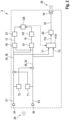
- the first input signal E1 is now superimposed with the second input signal E2, which has been delayed by a first delay parameter T1, and a first intermediate signal 34 is formed from this.
- the second input signal E2 is superimposed with the first input signal E1, which has been delayed by a second delay parameter T2, and a second intermediate signal 36 is formed as a result.
- the first calibration directional signal 12 is now calculated using the first intermediate signal 34 and the second intermediate signal 36.
- FIG. 1 by means of an adaptive directional microphone 40 such that the contributions of the first conversation partner 4 are maximally suppressed in the first calibration directional signal 12.
- the first instantaneous gain parameter G1 determined for the first calibration directional signal 12 therefore represents the optimal amplification and compression of the signal contributions of the second conversation partner 8.
- the second calibration directional signal 16 is generated from the first intermediate signal 34 and the second intermediate signal 36, which maximally suppresses the contributions of the second conversation partner 8. Since the latter is in a frontal direction to the wearer 1, as already mentioned, the second calibration directional signal 16 is given by the backward-directed cardioid directional signal 20. However, this situation can also change, so that a change in position of the second conversation partner 8 can also be taken into account by means of the adaptive directional microphone 42.
- the second instantaneous gain parameter G2 is now determined using the second calibration directional signal 16, and a relative gain parameter GR is formed from the latter and the first instantaneous gain parameter G1, which in this case is given by the quotient G2/G1.
- the relative gain parameter GR would result from the aforementioned linear combination of the first calibration directional signal 12 with the second calibration directional signal 16, each weighted with their corresponding instantaneous gain parameters G1 and G2, respectively, if the first instantaneous gain parameter G1 were used as the global gain parameter for the resulting signal of the linear combination, with the relative gain parameter GR in the first direction 6 producing exactly the correct signal strength for the speech contributions of the first conversation partner 4.
- the first intermediate signal 34 is used as a first processing directional signal Y1 and the second intermediate signal 36 is used as a second processing directional signal Y2 in the subsequent signal processing steps.
- a source-sensitive directional signal YQ is generated, which can optionally be subjected to further, unspecified signal processing steps 50, such as additional, frequency band-specific amplification, etc.
- An output signal 52 is thereby generated from the source-sensitive directional signal YQ, which is converted into an output sound signal 56 by an output transducer 54 of the hearing aid 2.
- the output transducer 54 can, for example, comprise a loudspeaker.
- the output sound signal 56 is then fed to the hearing of the wearer 1.
- X(w) is the frequency response of the sound signal 28
- w is the respective frequency
- A is a normalization factor
- i the imaginary unit.
- the circle position can be parameterized by an arc parameter ⁇ ⁇ [0, 2 ⁇ ) such that the relative depth D of the minimum of
- the relative depth D of the notch in the directional characteristic of the source-sensitive directional signal YQ caused by said attenuation as a function of this arc parameter ⁇ is given in Fig. 3
- the dependencies D( ⁇ ) shown there can be tabulated, so that a connection between a desired notch and the arc parameter sz for a is possible.
- the relative gain parameter GR which determines the relative attenuation in the directional characteristic of the source-sensitive directional signal YQ (based on the aforementioned tabulated dependencies on the arc parameter ⁇ of a), and the first instantaneous gain parameter G1 can thus be determined via the two degrees of freedom of the amount
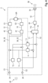
- FIG 4 is a schematic block diagram of an alternative embodiment of the method for directional signal processing according to Figure 2
- the determination of the relative gain parameter GR is completely identical to that in Figure 2 shown method, only the generation of the output signal 52 is changed in this case.
- is independent of the adaptation parameter m, so that the relative attenuation can be controlled via the latter as a function of the relative gain parameter GR, for example via corresponding tabulated values.
- the output signal 52 is now generated again using the source-sensitive directional signal YQ generated as described from the first and second processing directional signals Y1, Y2.
- the adaptation parameter m differently than in equation (iii), only in one of the two processing direction signals Y1, Y2 (for example in Y2), and to use the other processing direction signal (for example Y1) as the corresponding cardioid direction signal (for example the forward one 38).
Landscapes
- Physics & Mathematics (AREA)
- Engineering & Computer Science (AREA)
- Acoustics & Sound (AREA)
- Signal Processing (AREA)
- Health & Medical Sciences (AREA)
- General Health & Medical Sciences (AREA)
- Neurosurgery (AREA)
- Otolaryngology (AREA)
- Circuit For Audible Band Transducer (AREA)
Claims (10)
- Procédé de traitement directionnel du signal pour un appareil auditif (2),un premier signal d'entrée (E1) étant généré par un premier transducteur d'entrée (24) de l'appareil auditif (2) à partir d'un signal sonore (28) provenant de l'environnement,un second signal d'entrée (E2) étant généré par un second transducteur d'entrée (26) de l'appareil auditif (2) à partir du signal sonore (28) provenant de l'environnement,un premier signal intermédiaire (34) ainsi qu'un second signal intermédiaire (36) étant respectivement générés sur la base à la fois du premier signal d'entrée (E1) et du second signal d'entrée (E2),un premier signal directionnel d'étalonnage (12), qui présente une atténuation maximale dans la direction (6) d'une première source de signal utile (14) provenant de l'environnement, étant généré sur la base du premier signal intermédiaire (34) et sur la base du second signal intermédiaire (36),un second signal directionnel d'étalonnage (16), qui présente une atténuation maximale dans la direction (10) d'une seconde source de signal utile (18) provenant de l'environnement, étant généré sur la base du premier signal intermédiaire (34) et sur la base du second signal intermédiaire (36),un paramètre d'amplification relatif (GR) étant déterminé sur la base du premier signal directionnel d'étalonnage (12) et du second signal directionnel d'étalonnage (16),- en déterminant un premier paramètre d'amplification instantané (G1) sur la base du premier signal directionnel d'étalonnage (12),- en déterminant un second paramètre d'amplification instantané (G2) sur la base du second signal directionnel d'étalonnage (16), et- en déterminant le paramètre d'amplification relatif (GR) sur la base du premier paramètre d'amplification instantané (G1) et du second paramètre d'amplification instantané (G2),un premier signal directionnel de traitement (Y1) ainsi qu'un second signal directionnel de traitement (Y2) étant respectivement générés sur la base à la fois du premier signal d'entrée (E1) et du second signal d'entrée (E2),en conséquence, le premier signal directionnel de traitement (Y1) étant généré à partir du premier signal intermédiaire (34), et le second signal directionnel de traitement (Y2) étant généré à partir du second signal intermédiaire (36),un signal directionnel sensible à la source (YQ) étant généré sur la base du premier signal directionnel de traitement (Y1), du second signal directionnel de traitement (Y2) et du paramètre d'amplification relatif (GR),- en fixant une intensité de signal de référence dans la direction (10) de la seconde source de signal utile (18),- en déterminant une intensité de signal déduite dans la direction (6) de la première source de signal utile (14) sur la base du paramètre d'amplification relatif (GR) et sur la base de l'intensité de signal de référence, et- sur la base de l'intensité de signal déduite, en déterminant un paramètre de superposition complexe (a) pour une superposition du premier signal directionnel de traitement (Y1) avec le second signal directionnel de traitement (Y2) et en générant le signal directionnel sensible à la source (YQ) sur la base de ladite superposition,et un signal de sortie (52) de l'appareil auditif (2) étant généré sur la base du signal directionnel sensible à la source (YQ).
- Procédé selon l'une des revendications précédentes, le premier signal directionnel d'étalonnage (12) étant généré au moyen d'un système de microphone directionnel adaptatif (40), et/ou
le second signal directionnel d'étalonnage (16) étant généré au moyen d'un système de microphone directionnel adaptatif (42). - Procédé selon la revendication 1 ou la revendication 2,le premier signal intermédiaire (34) étant généré sur la base d'une superposition retardée dans le temps du premier signal d'entrée (E1) avec le second signal d'entrée (E2), mise en œuvre au moyen d'un premier paramètre de retard (T1), et/oule second signal intermédiaire (36) étant généré sur la base d'une superposition retardée dans le temps du second signal d'entrée (E2) avec le premier signal d'entrée (E1), mise en œuvre au moyen d'un second paramètre de retard (T2).
- Procédé selon la revendication 3,le premier signal intermédiaire (34) étant généré sous la forme d'un signal directionnel cardioïde dirigé vers l'avant (38), et/oule second signal intermédiaire (36) étant généré sous la forme d'un signal directionnel cardioïde dirigé vers l'arrière (20).
- Procédé de traitement directionnel du signal pour un appareil auditif (2),un premier signal d'entrée (E1) étant généré par un premier transducteur d'entrée (24) de l'appareil auditif (2) à partir d'un signal sonore (28) provenant de l'environnement,un second signal d'entrée (E2) étant généré par un second transducteur d'entrée (26) de l'appareil auditif (2) à partir du signal sonore (28) provenant de l'environnement,un premier signal directionnel d'étalonnage (12), qui présente une atténuation maximale dans la direction (6) d'une première source de signal utile (14) de l'environnement, étant généré sur la base du premier signal d'entrée (E1) et sur la base du second signal d'entrée (E2),un second signal directionnel d'étalonnage (16), qui présente une atténuation maximale dans la direction (10) d'une seconde source de signal utile (18) de l'environnement, étant généré sur la base du premier signal d'entrée (20) et sur la base du second signal d'entrée (E2),un paramètre d'amplification relatif (GR) étant déterminé sur la base du premier signal directionnel d'étalonnage (12) et du second signal directionnel d'étalonnage (16),- en déterminant un premier paramètre d'amplification instantané (G1) sur la base du premier signal directionnel d'étalonnage (12),- en déterminant un second paramètre d'amplification instantané (G2) sur la base du second signal directionnel d'étalonnage (16), et- le paramètre d'amplification relatif (GR) est déterminé sur la base du premier paramètre d'amplification instantané (G1) et du second paramètre d'amplification instantané (G2),un premier signal directionnel de traitement (Y1) ainsi qu'un second signal directionnel de traitement (Y2) étant respectivement générés sur la base à la fois du premier signal d'entrée (E1) et du second signal d'entrée (E2), en conséquence, le premier signal directionnel de traitement (Y1) étant formé sur la base d'une superposition retardée dans le temps du premier signal d'entrée (E1) avec le second signal d'entrée (E2), mise en œuvre au moyen de premiers facteurs de pondération asymétriques (m), en tant que premier signal de superposition asymétrique, et/oule second signal directionnel de traitement (Y2) étant formé sur la base d'une superposition retardée dans le temps du second signal d'entrée (E2) avec le premier signal d'entrée (E1), mise en œuvre au moyen de seconds facteurs de pondération asymétriques (m), en tant que second signal de superposition asymétrique,un signal directionnel sensible à la source (YQ) étant généré sur la base du premier signal directionnel de traitement (Y1), du second signal directionnel de traitement (Y2) et du paramètre d'amplification relatif (GR),- en fixant une intensité de signal de référence dans la direction (10) de la seconde source de signal utile (18),- en déterminant une intensité de signal déduite dans la direction (6) de la première source de signal utile (14) sur la base du paramètre d'amplification relatif (GR) et sur la base de l'intensité de signal de référence,- sur la base de l'intensité de signal déduite,-- en déterminant un paramètre de superposition complexe (a) pour une superposition du premier signal directionnel de traitement (Y1) avec le second signal directionnel de traitement (Y2), et/ou-- en déterminant les premiers (m) et/ou seconds facteurs de pondération asymétriques (m) pour le premier et/ou le second signal de superposition asymétrique,- et en générant le signal directionnel sensible à la source (YQ) sur la base de ladite superposition du premier signal directionnel de traitement (Y1) avec le second signal directionnel de traitement (Y2),et un signal de sortie (52) de l'appareil auditif (2) étant généré sur la base du signal directionnel sensible à la source (YQ).
- Procédé selon la revendication 5,un premier signal intermédiaire (34) ainsi qu'un second signal intermédiaire (36) étant respectivement générés sur la base à la fois du premier signal d'entrée (E1) et du second signal d'entrée (E2), etle premier signal directionnel d'étalonnage (12) et le second signal directionnel d'étalonnage (16) étant tous deux respectivement générés sur la base à la fois du premier signal intermédiaire (34) et du second signal intermédiaire (36).
- Procédé selon la revendication 6,le premier signal intermédiaire (34) étant généré sur la base d'une superposition retardée dans le temps du premier signal d'entrée (E1) avec le second signal d'entrée (E2), mise en œuvre au moyen d'un premier paramètre de retard (T1), et/oule second signal intermédiaire (36) étant généré sur la base d'une superposition retardée dans le temps du second signal d'entrée (E2) avec le premier signal d'entrée (E1), mise en œuvre au moyen d'un second paramètre de retard (T2).
- Procédé selon la revendication 6 ou la revendication 7,le premier signal intermédiaire (34) étant généré sous la forme d'un signal directionnel cardioïde dirigé vers l'avant (38), et/oule second signal intermédiaire (36) étant généré sous la forme d'un signal directionnel cardioïde dirigé vers l'arrière (20).
- Procédé selon l'une des revendications 5 à 8,le premier signal directionnel d'étalonnage (12) étant généré au moyen d'un système de microphone directionnel adaptatif (40), et/oule second signal directionnel d'étalonnage (16) étant généré au moyen d'un système de microphone directionnel adaptatif (42).
- Système auditif comprenant- un appareil auditif (2), qui comporte un premier transducteur d'entrée (24) destiné à générer un premier signal d'entrée (E1) à partir d'un signal sonore (28) provenant de l'environnement ainsi qu'un second transducteur d'entrée (26) destiné à générer un second signal d'entrée (E2) à partir du signal sonore (28) provenant de l'environnement, et- une unité de commande qui est conçue pour mettre en œuvre le procédé selon l'une des revendications précédentes.
Applications Claiming Priority (1)
| Application Number | Priority Date | Filing Date | Title |
|---|---|---|---|
| DE102019205709.8A DE102019205709B3 (de) | 2019-04-18 | 2019-04-18 | Verfahren zur direktionalen Signalverarbeitung für ein Hörgerät |
Publications (3)
| Publication Number | Publication Date |
|---|---|
| EP3726853A1 EP3726853A1 (fr) | 2020-10-21 |
| EP3726853C0 EP3726853C0 (fr) | 2024-11-27 |
| EP3726853B1 true EP3726853B1 (fr) | 2024-11-27 |
Family
ID=69526106
Family Applications (1)
| Application Number | Title | Priority Date | Filing Date |
|---|---|---|---|
| EP20155945.7A Active EP3726853B1 (fr) | 2019-04-18 | 2020-02-06 | Procédé de traitement directionnel du signal pour un appareil auditif |
Country Status (4)
| Country | Link |
|---|---|
| US (1) | US11070923B2 (fr) |
| EP (1) | EP3726853B1 (fr) |
| CN (1) | CN111836162B (fr) |
| DE (1) | DE102019205709B3 (fr) |
Families Citing this family (4)
| Publication number | Priority date | Publication date | Assignee | Title |
|---|---|---|---|---|
| DE102020209555A1 (de) | 2020-07-29 | 2022-02-03 | Sivantos Pte. Ltd. | Verfahren zur direktionalen Signalverarbeitung für ein Hörgerät |
| DE102020210805B3 (de) * | 2020-08-26 | 2022-02-10 | Sivantos Pte. Ltd. | Verfahren zur direktionalen Signalverarbeitung für ein akustisches System |
| DE102021210098A1 (de) | 2021-09-13 | 2023-03-16 | Sivantos Pte. Ltd. | Verfahren zum Betrieb eines Hörgeräts |
| DE102022206916B4 (de) * | 2022-07-06 | 2025-04-10 | Sivantos Pte. Ltd. | Hörinstrument und Verfahren zur direktionalen Signalverarbeitung für ein Hörinstrument |
Family Cites Families (16)
| Publication number | Priority date | Publication date | Assignee | Title |
|---|---|---|---|---|
| JP2003527012A (ja) * | 2000-03-14 | 2003-09-09 | オーディア テクノロジー インク | 多重マイクロフォン方向システムにおける順応型マイクロフォン・マッチング |
| US6865275B1 (en) * | 2000-03-31 | 2005-03-08 | Phonak Ag | Method to determine the transfer characteristic of a microphone system, and microphone system |
| US6704422B1 (en) * | 2000-10-26 | 2004-03-09 | Widex A/S | Method for controlling the directionality of the sound receiving characteristic of a hearing aid a hearing aid for carrying out the method |
| US7630507B2 (en) | 2002-01-28 | 2009-12-08 | Gn Resound A/S | Binaural compression system |
| US7369669B2 (en) * | 2002-05-15 | 2008-05-06 | Micro Ear Technology, Inc. | Diotic presentation of second-order gradient directional hearing aid signals |
| DE102004010867B3 (de) * | 2004-03-05 | 2005-08-18 | Siemens Audiologische Technik Gmbh | Verfahren und Vorrichtung zum Anpassen der Phasen von Mikrofonen eines Hörgeräterichtmikrofons |
| EP2107826A1 (fr) * | 2008-03-31 | 2009-10-07 | Bernafon AG | Système d'assistance auditive directionnelle |
| US8477973B2 (en) * | 2009-04-01 | 2013-07-02 | Starkey Laboratories, Inc. | Hearing assistance system with own voice detection |
| WO2011017748A1 (fr) * | 2009-08-11 | 2011-02-17 | Hear Ip Pty Ltd | Système et procédé d'estimation de la direction d'arrivée d'un son |
| DE102010011730A1 (de) * | 2010-03-17 | 2011-11-17 | Siemens Medical Instruments Pte. Ltd. | Hörvorrichtung und Verfahren zum Erzeugen einer omnidirektionalen Richtcharakteristik |
| US9241223B2 (en) * | 2014-01-31 | 2016-01-19 | Malaspina Labs (Barbados) Inc. | Directional filtering of audible signals |
| DE102015210652B4 (de) * | 2015-06-10 | 2019-08-08 | Sivantos Pte. Ltd. | Verfahren zur Verbesserung eines Aufnahmesignals in einem Hörsystem |
| DE102015211747B4 (de) * | 2015-06-24 | 2017-05-18 | Sivantos Pte. Ltd. | Verfahren zur Signalverarbeitung in einem binauralen Hörgerät |
| DE102016225207A1 (de) | 2016-12-15 | 2018-06-21 | Sivantos Pte. Ltd. | Verfahren zum Betrieb eines Hörgerätes |
| DE102017206788B3 (de) * | 2017-04-21 | 2018-08-02 | Sivantos Pte. Ltd. | Verfahren zum Betrieb eines Hörgerätes |
| DE102017215823B3 (de) * | 2017-09-07 | 2018-09-20 | Sivantos Pte. Ltd. | Verfahren zum Betrieb eines Hörgerätes |
-
2019
- 2019-04-18 DE DE102019205709.8A patent/DE102019205709B3/de active Active
-
2020
- 2020-02-06 EP EP20155945.7A patent/EP3726853B1/fr active Active
- 2020-04-07 US US16/841,869 patent/US11070923B2/en active Active
- 2020-04-17 CN CN202010304839.XA patent/CN111836162B/zh active Active
Also Published As
| Publication number | Publication date |
|---|---|
| EP3726853C0 (fr) | 2024-11-27 |
| CN111836162A (zh) | 2020-10-27 |
| EP3726853A1 (fr) | 2020-10-21 |
| DE102019205709B3 (de) | 2020-07-09 |
| US11070923B2 (en) | 2021-07-20 |
| CN111836162B (zh) | 2021-12-28 |
| US20200336844A1 (en) | 2020-10-22 |
Similar Documents
| Publication | Publication Date | Title |
|---|---|---|
| EP3726853B1 (fr) | Procédé de traitement directionnel du signal pour un appareil auditif | |
| EP3461147B1 (fr) | Procédé de fonctionnement d'un appareil auditif | |
| EP3926982B1 (fr) | Procédé de réduction directionnelle du bruit pour un système auditif comprenant un dispositif auditif | |
| EP1307072A2 (fr) | Procédé pour actionner une prothèse auditive et prothèse auditive | |
| DE102013207149A1 (de) | Steuerung der Effektstärke eines binauralen direktionalen Mikrofons | |
| EP3393143B1 (fr) | Procédé de fonctionnement d'une aide auditive | |
| DE202019107201U1 (de) | Binaurales Hörgerät für eine verbesserte räumliche Hörwahrnehmung | |
| DE102020210805B3 (de) | Verfahren zur direktionalen Signalverarbeitung für ein akustisches System | |
| EP3772861B1 (fr) | Procédé de traitement directionnel du signal pour un appareil auditif | |
| EP3945733B1 (fr) | Procédé de traitement directionnel du signal pour un appareil auditif | |
| DE102020107620B3 (de) | System und Verfahren zur Kompensation des Okklusionseffektes bei Kopfhörern oder Hörhilfen mit verbesserter Wahrnehmung der eigenen Stimme | |
| EP4247007B1 (fr) | Procédé de fonctionnement d'un système auditif binaural | |
| EP3793217A1 (fr) | Appareil auditif avec annulation active du bruit et procédé de fonctionnement de lequel | |
| DE202019107200U1 (de) | Binaurales Hörgerät | |
| DE102023202437A1 (de) | Verfahren zur Lokalisierung einer Schallquelle für ein binaurales Hörsystem | |
| DE102018203907B4 (de) | Verfahren zum Betrieb eines Hörgerätes | |
| EP1916872B1 (fr) | Système de microphone directionnel différentiel et appareil auditif doté d'un tel système de microphone directionnel différentiel | |
| DE102010041644A1 (de) | Verfahren zur Frequenzkompression mit harmonischer Korrektur und Vorrichtung | |
| DE102022206916B4 (de) | Hörinstrument und Verfahren zur direktionalen Signalverarbeitung für ein Hörinstrument | |
| DE102023202422B4 (de) | Verfahren zur direktionalen Signalverarbeitung für ein binaurales Hörsystem | |
| EP3534624B1 (fr) | Procédé de fonctionnement d'un dispositif de correction auditive | |
| DE102023208468A1 (de) | Verfahren zur direktionalen Signalverarbeitung für ein Hörsystem | |
| DE19844748A1 (de) | Verfahren zum Bereitstellen einer Richtmikrofoncharakteristik und Hörgerät | |
| WO2025223697A1 (fr) | Procédé de traitement de signal directionnel pour instrument auditif | |
| DE102020202206A1 (de) | Verfahren zur Unterdrückung eines Eigenrauschens einer Mikrofonanordnung |
Legal Events
| Date | Code | Title | Description |
|---|---|---|---|
| PUAI | Public reference made under article 153(3) epc to a published international application that has entered the european phase |
Free format text: ORIGINAL CODE: 0009012 |
|
| STAA | Information on the status of an ep patent application or granted ep patent |
Free format text: STATUS: THE APPLICATION HAS BEEN PUBLISHED |
|
| AK | Designated contracting states |
Kind code of ref document: A1 Designated state(s): AL AT BE BG CH CY CZ DE DK EE ES FI FR GB GR HR HU IE IS IT LI LT LU LV MC MK MT NL NO PL PT RO RS SE SI SK SM TR |
|
| AX | Request for extension of the european patent |
Extension state: BA ME |
|
| STAA | Information on the status of an ep patent application or granted ep patent |
Free format text: STATUS: REQUEST FOR EXAMINATION WAS MADE |
|
| 17P | Request for examination filed |
Effective date: 20210419 |
|
| RBV | Designated contracting states (corrected) |
Designated state(s): AL AT BE BG CH CY CZ DE DK EE ES FI FR GB GR HR HU IE IS IT LI LT LU LV MC MK MT NL NO PL PT RO RS SE SI SK SM TR |
|
| STAA | Information on the status of an ep patent application or granted ep patent |
Free format text: STATUS: EXAMINATION IS IN PROGRESS |
|
| 17Q | First examination report despatched |
Effective date: 20221114 |
|
| GRAP | Despatch of communication of intention to grant a patent |
Free format text: ORIGINAL CODE: EPIDOSNIGR1 |
|
| STAA | Information on the status of an ep patent application or granted ep patent |
Free format text: STATUS: GRANT OF PATENT IS INTENDED |
|
| INTG | Intention to grant announced |
Effective date: 20240716 |
|
| GRAS | Grant fee paid |
Free format text: ORIGINAL CODE: EPIDOSNIGR3 |
|
| GRAA | (expected) grant |
Free format text: ORIGINAL CODE: 0009210 |
|
| STAA | Information on the status of an ep patent application or granted ep patent |
Free format text: STATUS: THE PATENT HAS BEEN GRANTED |
|
| AK | Designated contracting states |
Kind code of ref document: B1 Designated state(s): AL AT BE BG CH CY CZ DE DK EE ES FI FR GB GR HR HU IE IS IT LI LT LU LV MC MK MT NL NO PL PT RO RS SE SI SK SM TR |
|
| REG | Reference to a national code |
Ref country code: GB Ref legal event code: FG4D Free format text: NOT ENGLISH |
|
| REG | Reference to a national code |
Ref country code: CH Ref legal event code: EP |
|
| REG | Reference to a national code |
Ref country code: DE Ref legal event code: R096 Ref document number: 502020009808 Country of ref document: DE |
|
| REG | Reference to a national code |
Ref country code: IE Ref legal event code: FG4D Free format text: LANGUAGE OF EP DOCUMENT: GERMAN |
|
| U01 | Request for unitary effect filed |
Effective date: 20241204 |
|
| U07 | Unitary effect registered |
Designated state(s): AT BE BG DE DK EE FI FR IT LT LU LV MT NL PT RO SE SI Effective date: 20241216 |
|
| U20 | Renewal fee for the european patent with unitary effect paid |
Year of fee payment: 6 Effective date: 20250121 |
|
| PG25 | Lapsed in a contracting state [announced via postgrant information from national office to epo] |
Ref country code: HR Free format text: LAPSE BECAUSE OF FAILURE TO SUBMIT A TRANSLATION OF THE DESCRIPTION OR TO PAY THE FEE WITHIN THE PRESCRIBED TIME-LIMIT Effective date: 20241127 Ref country code: IS Free format text: LAPSE BECAUSE OF FAILURE TO SUBMIT A TRANSLATION OF THE DESCRIPTION OR TO PAY THE FEE WITHIN THE PRESCRIBED TIME-LIMIT Effective date: 20250327 |
|
| PG25 | Lapsed in a contracting state [announced via postgrant information from national office to epo] |
Ref country code: ES Free format text: LAPSE BECAUSE OF FAILURE TO SUBMIT A TRANSLATION OF THE DESCRIPTION OR TO PAY THE FEE WITHIN THE PRESCRIBED TIME-LIMIT Effective date: 20241127 |
|
| PG25 | Lapsed in a contracting state [announced via postgrant information from national office to epo] |
Ref country code: NO Free format text: LAPSE BECAUSE OF FAILURE TO SUBMIT A TRANSLATION OF THE DESCRIPTION OR TO PAY THE FEE WITHIN THE PRESCRIBED TIME-LIMIT Effective date: 20250227 |
|
| PG25 | Lapsed in a contracting state [announced via postgrant information from national office to epo] |
Ref country code: GR Free format text: LAPSE BECAUSE OF FAILURE TO SUBMIT A TRANSLATION OF THE DESCRIPTION OR TO PAY THE FEE WITHIN THE PRESCRIBED TIME-LIMIT Effective date: 20250228 |
|
| PGFP | Annual fee paid to national office [announced via postgrant information from national office to epo] |
Ref country code: CH Payment date: 20250301 Year of fee payment: 6 |
|
| PG25 | Lapsed in a contracting state [announced via postgrant information from national office to epo] |
Ref country code: PL Free format text: LAPSE BECAUSE OF FAILURE TO SUBMIT A TRANSLATION OF THE DESCRIPTION OR TO PAY THE FEE WITHIN THE PRESCRIBED TIME-LIMIT Effective date: 20241127 |
|
| PG25 | Lapsed in a contracting state [announced via postgrant information from national office to epo] |
Ref country code: RS Free format text: LAPSE BECAUSE OF FAILURE TO SUBMIT A TRANSLATION OF THE DESCRIPTION OR TO PAY THE FEE WITHIN THE PRESCRIBED TIME-LIMIT Effective date: 20250227 |
|
| PG25 | Lapsed in a contracting state [announced via postgrant information from national office to epo] |
Ref country code: SM Free format text: LAPSE BECAUSE OF FAILURE TO SUBMIT A TRANSLATION OF THE DESCRIPTION OR TO PAY THE FEE WITHIN THE PRESCRIBED TIME-LIMIT Effective date: 20241127 |
|
| PG25 | Lapsed in a contracting state [announced via postgrant information from national office to epo] |
Ref country code: SK Free format text: LAPSE BECAUSE OF FAILURE TO SUBMIT A TRANSLATION OF THE DESCRIPTION OR TO PAY THE FEE WITHIN THE PRESCRIBED TIME-LIMIT Effective date: 20241127 |
|
| PG25 | Lapsed in a contracting state [announced via postgrant information from national office to epo] |
Ref country code: CZ Free format text: LAPSE BECAUSE OF FAILURE TO SUBMIT A TRANSLATION OF THE DESCRIPTION OR TO PAY THE FEE WITHIN THE PRESCRIBED TIME-LIMIT Effective date: 20241127 |
|
| PG25 | Lapsed in a contracting state [announced via postgrant information from national office to epo] |
Ref country code: MC Free format text: LAPSE BECAUSE OF FAILURE TO SUBMIT A TRANSLATION OF THE DESCRIPTION OR TO PAY THE FEE WITHIN THE PRESCRIBED TIME-LIMIT Effective date: 20241127 |
|
| PLBE | No opposition filed within time limit |
Free format text: ORIGINAL CODE: 0009261 |
|
| STAA | Information on the status of an ep patent application or granted ep patent |
Free format text: STATUS: NO OPPOSITION FILED WITHIN TIME LIMIT |
|
| REG | Reference to a national code |
Ref country code: CH Ref legal event code: L10 Free format text: ST27 STATUS EVENT CODE: U-0-0-L10-L00 (AS PROVIDED BY THE NATIONAL OFFICE) Effective date: 20251008 |
|
| 26N | No opposition filed |
Effective date: 20250828 |
|
| PG25 | Lapsed in a contracting state [announced via postgrant information from national office to epo] |
Ref country code: IE Free format text: LAPSE BECAUSE OF NON-PAYMENT OF DUE FEES Effective date: 20250206 |
|
| U20 | Renewal fee for the european patent with unitary effect paid |
Year of fee payment: 7 Effective date: 20260121 |
|
| REG | Reference to a national code |
Ref country code: CH Ref legal event code: U11 Free format text: ST27 STATUS EVENT CODE: U-0-0-U10-U11 (AS PROVIDED BY THE NATIONAL OFFICE) Effective date: 20260301 |
|
| PGFP | Annual fee paid to national office [announced via postgrant information from national office to epo] |
Ref country code: GB Payment date: 20260121 Year of fee payment: 7 |