EP3727995B1 - Colonne de direction à réglage motorisé pour véhicule à moteur - Google Patents
Colonne de direction à réglage motorisé pour véhicule à moteur Download PDFInfo
- Publication number
- EP3727995B1 EP3727995B1 EP18829772.5A EP18829772A EP3727995B1 EP 3727995 B1 EP3727995 B1 EP 3727995B1 EP 18829772 A EP18829772 A EP 18829772A EP 3727995 B1 EP3727995 B1 EP 3727995B1
- Authority
- EP
- European Patent Office
- Prior art keywords
- spindle
- steering column
- spindle nut
- steering
- nut
- Prior art date
- Legal status (The legal status is an assumption and is not a legal conclusion. Google has not performed a legal analysis and makes no representation as to the accuracy of the status listed.)
- Active
Links
Images


Classifications
-
- B—PERFORMING OPERATIONS; TRANSPORTING
- B62—LAND VEHICLES FOR TRAVELLING OTHERWISE THAN ON RAILS
- B62D—MOTOR VEHICLES; TRAILERS
- B62D1/00—Steering controls, i.e. means for initiating a change of direction of the vehicle
- B62D1/02—Steering controls, i.e. means for initiating a change of direction of the vehicle vehicle-mounted
- B62D1/16—Steering columns
- B62D1/18—Steering columns yieldable or adjustable, e.g. tiltable
- B62D1/19—Steering columns yieldable or adjustable, e.g. tiltable incorporating energy-absorbing arrangements, e.g. by being yieldable or collapsible
-
- B—PERFORMING OPERATIONS; TRANSPORTING
- B62—LAND VEHICLES FOR TRAVELLING OTHERWISE THAN ON RAILS
- B62D—MOTOR VEHICLES; TRAILERS
- B62D1/00—Steering controls, i.e. means for initiating a change of direction of the vehicle
- B62D1/02—Steering controls, i.e. means for initiating a change of direction of the vehicle vehicle-mounted
- B62D1/16—Steering columns
- B62D1/18—Steering columns yieldable or adjustable, e.g. tiltable
- B62D1/181—Steering columns yieldable or adjustable, e.g. tiltable with power actuated adjustment, e.g. with position memory
-
- B—PERFORMING OPERATIONS; TRANSPORTING
- B62—LAND VEHICLES FOR TRAVELLING OTHERWISE THAN ON RAILS
- B62D—MOTOR VEHICLES; TRAILERS
- B62D1/00—Steering controls, i.e. means for initiating a change of direction of the vehicle
- B62D1/02—Steering controls, i.e. means for initiating a change of direction of the vehicle vehicle-mounted
- B62D1/16—Steering columns
- B62D1/18—Steering columns yieldable or adjustable, e.g. tiltable
- B62D1/185—Steering columns yieldable or adjustable, e.g. tiltable adjustable by axial displacement, e.g. telescopically
-
- B—PERFORMING OPERATIONS; TRANSPORTING
- B62—LAND VEHICLES FOR TRAVELLING OTHERWISE THAN ON RAILS
- B62D—MOTOR VEHICLES; TRAILERS
- B62D1/00—Steering controls, i.e. means for initiating a change of direction of the vehicle
- B62D1/02—Steering controls, i.e. means for initiating a change of direction of the vehicle vehicle-mounted
- B62D1/16—Steering columns
- B62D1/18—Steering columns yieldable or adjustable, e.g. tiltable
- B62D1/19—Steering columns yieldable or adjustable, e.g. tiltable incorporating energy-absorbing arrangements, e.g. by being yieldable or collapsible
- B62D1/192—Yieldable or collapsible columns
-
- B—PERFORMING OPERATIONS; TRANSPORTING
- B62—LAND VEHICLES FOR TRAVELLING OTHERWISE THAN ON RAILS
- B62D—MOTOR VEHICLES; TRAILERS
- B62D1/00—Steering controls, i.e. means for initiating a change of direction of the vehicle
- B62D1/02—Steering controls, i.e. means for initiating a change of direction of the vehicle vehicle-mounted
- B62D1/16—Steering columns
- B62D1/18—Steering columns yieldable or adjustable, e.g. tiltable
- B62D1/19—Steering columns yieldable or adjustable, e.g. tiltable incorporating energy-absorbing arrangements, e.g. by being yieldable or collapsible
- B62D1/195—Yieldable supports for the steering column
Definitions
- the invention relates to a motor-adjustable steering column for a motor vehicle, comprising an outer jacket which is held by a support unit which can be attached to a vehicle body and in which an adjusting unit is accommodated, adjustable in the longitudinal direction, in which a steering spindle is mounted coaxially in a jacket tube so that it can rotate about a longitudinal axis , wherein an adjusting drive and an energy absorbing device are arranged between the outer jacket and the adjusting unit, wherein the adjusting drive has a spindle drive with a threaded spindle, which engages in a spindle nut so that it can be rotated by an electric adjusting motor, and the energy absorbing device has at least one which is arranged at least indirectly between the spindle nut and the adjusting unit Includes energy absorbing element.
- a steering column for a motor vehicle has a steering shaft with a steering spindle, at the rear end of which, in the direction of travel, facing the driver, a steering wheel is attached for introducing steering commands.
- the steering spindle is rotatably mounted about its longitudinal axis in the actuating unit in an inner jacket tube, also called jacket tube or inner jacket for short.
- the control unit is accommodated in an outer shell, also referred to as a shell unit, rocker box or guide box, which is held on the vehicle body via a support unit.
- the adjustment of the control unit in the lengthwise or heightwise direction enables an ergonomically comfortable steering wheel position to be set relative to the driver's position in the operating position, also known as the driving or operating position, in which manual steering intervention can take place.
- a length adjustment can be realized in that the actuating unit is accommodated in the outer casing in the longitudinal direction, which corresponds to the direction of the longitudinal axis, so that it can be displaced telescopically, as in the prior art, for example in FIG DE 10 2017 207 561 A1 or the DE 10 2015 224 602 A1 described.
- a linear motorized adjustment drive is provided for executing the adjustment movement of the control unit relative to the outer jacket, which is designed as a spindle drive with a threaded spindle screwed into a spindle nut, which can be driven in rotation relative to the spindle nut by an electric motor.
- the lead screw and the lead screw nut support each other in the longitudinal direction between the control unit and the outer jacket, so that depending on the relative direction of rotation, the control unit is telescopically retracted or extended relative to the outer jacket.
- a height adjustment can optionally be implemented in that the setting unit or the outer jacket is mounted pivotably on the support unit and, if necessary, can also be adjusted by means of an electric adjustment drive.
- Motor-adjustable steering columns offer an increase in driving and operating comfort, for example, in that individual steering wheel positions can be electronically stored for different drivers and automatically called up and adjusted if necessary. It is also of particular interest that the steering column can be automatically adjusted to predetermined positions in certain operating situations. For example, with autonomous driving, no manual steering intervention by the driver is required while driving, so that the steering wheel can in principle be brought into a stowed position outside of the operating position in order to be able to alternatively use the vehicle interior that is freed up as a result.
- an energy absorption device also known as a crash device, is coupled between the outer shell and the actuating unit, which are positioned relative to one another in the adjusted adjustment position during normal operation.
- This converts the kinetic energy introduced into the actuating unit in the longitudinal direction via the steering wheel into plastic deformation of an energy absorption element, for example by tearing open a tear-off tab or bending an elongated flexible element, such as a flexible wire or flexible strip.
- a steering column with the features mentioned is from the U.S. 2015/232117 A1 famous.
- the spindle nut and/or the threaded spindle has at least one deforming element which is in operative engagement with the energy absorption element and of which the energy absorption element is plastically deformable.
- the spindle drive is arranged in series with the energy absorption element in the direction of the power flow in the event of a relative displacement in the event of a crash between the outer casing and the actuating unit, as is known per se for the functionality of energy absorption.
- the energy absorption element is moved relative to the deforming element, which is formed on the spindle drive.
- At least one deforming element is formed on the spindle nut, for example between the spindle nut and the actuating unit, which is carried along by the spindle nut in the longitudinal direction during adjustment during normal operation and is only moved relative to the spindle nut in the event of a crash.
- the inventive deforming element acts on the energy absorbing element carried along by the actuating unit and moved relative to the spindle nut so that it is plastically deformed at least over a part of its longitudinal extension, converting kinetic energy into deformation work.
- the deforming element is preferably arranged on the functional element that is non-rotatably attached with respect to the relative rotation of the spindle drive relative to the steering column, for example on a spindle nut, which is supported non-rotatably on the actuating unit and into which the threaded spindle that can be driven in rotation engages, whereby a so-called rotary spindle drive is formed.
- the threaded spindle can have at least one reshaping element which, in the event of a crash, causes reshaping of the energy absorption element that is moved relative thereto.
- the deforming element is designed to be integrated with the spindle nut, preferably in one piece.
- a particularly compact design can be achieved by the deforming element integrated in the spindle nut.
- a one-piece integration which can be done by machining and/or non-machining deformation of the spindle nut, can be manufactured in a space-saving and efficient manner, and high stability and functional reliability of the energy absorption device can be guaranteed.
- the spindle nut is formed from a plastic, for example from a polyoxymethylene.
- the spindle nut and the forming element according to the invention can thus be produced in a simple and cost-effective manner.
- the spindle nut is formed from a non-ferrous metal such as brass.
- a combination of non-ferrous metal and plastic is also conceivable and possible.
- the deforming element in the case of a plunger spindle drive, it is conceivable for the deforming element to be integrated with the threaded spindle, preferably in one piece.
- the jacket tube can be designed as a cast part, for example made of aluminum, magnesium or other metal alloys. It can be efficiently manufactured as a continuously cast profile, in which an endless hollow profile is produced with the same cross-section throughout, from which the casing pipe is cut to the required length. Alternatively, the casing tube can be manufactured as a shaped sheet metal part.
- the energy absorption element can preferably be designed as an elongate bending wire with a length that can be moved relative to the deforming element and deformed by the deforming element at least partially along its length.
- a bending wire can be designed as an elongated bending strip with a round or angular cross section. In the event of a crash, the bending wire is moved over at least part of its length relative to at least one forming element, with the forming element bringing about a plastic deformation, for example a bending that is continuously moved along the longitudinal extent of the bending wire, or a plastic deformation of the wire cross section.
- a bending wire is simple and inexpensive to manufacture and assemble and has defined, specifiable, controllable energy absorption properties.
- the cross section of the bending wire varies over the length, so that a targeted force-displacement characteristic can be achieved in the event of a crash. It can thus be achieved, for example, that the crash force increases continuously with the crash distance covered.
- the forming element can have at least one bending anvil around which the bending wire is bent transversely to the longitudinal axis, preferably by 180°.
- the bending wire or bending strip is guided around at least one bending anvil in a bend which, when the bending wire is pulled along the spindle nut or the threaded spindle over at least part of its length in the event of a crash, moves over at least part of the longitudinal extent of the bending wire with continuous bending deformation, whereby kinetic energy is continuously absorbed.
- the bending wire can be fixed at a first end to the actuating unit and can extend with a first leg counter to the longitudinal direction up to a bend that nestles against a bending anvil, and which can preferably be around 180°.
- the bend is followed by a second leg, which preferably extends in the opposite direction to the first leg, ie in the longitudinal direction.
- the second leg of the bending wire is moved around the bending anvil, passing through the bend and the first leg adjoining it being lengthened.
- the bending wire With regard to assembly, it is advantageous for the bending wire to have a first end connected to the actuating unit and a second, free end.
- the first end of the bending wire can have a fastening section which is connected to the actuating unit and is moved in the longitudinal direction relative to the forming element in the event of a crash.
- the second end of the bending wire is designed as a free end which is not connected to the spindle nut, the threaded spindle or the outer casing, but protrudes loosely from the deforming element of the spindle nut with its section lying in front of the operative engagement.
- the spindle nut and/or the threaded spindle has at least one guide element.
- the energy absorption element is guided by the guide element, so that the deformation takes place in a controlled manner and a defined energy absorption characteristic is accordingly ensured.
- a guide element can be designed as a guide groove in the form of a recess running in the longitudinal direction, in which an energy absorption element designed as a bending wire or strip is guided in the longitudinal direction, in which it can slide along, for example, to a bending anvil in the event of a crash.
- One or more guide elements are preferably formed in one piece with the spindle nut, for example as molded-in groove-shaped recesses that serve as guide grooves.
- the bending wire or strip is guided in a recess in the direction of its longitudinal extent, so that in the event of a crash it slides along guided therein during a relative movement to the spindle nut or to the threaded spindle.
- the predetermined breaking element connects the spindle nut or the threaded spindle to the actuating unit for transmission of the adjustment movement.
- a defined, high limit force is exceeded in the longitudinal direction between the spindle drive supported on the outer casing and the actuating unit, which only occurs in the event of a crash, the predetermined breaking element is separated or broken free and then releases the relative movement of the actuating unit to deform the energy absorption element.
- the predetermined breaking element can be designed as a shear pin, for example.
- the response behavior of the energy absorption can be specified in a defined manner by the controlled breaking away, so that the energy absorption device is only mechanically stressed in the event of a crash, which increases the functional reliability.
- a motor-driven adjustable steering column for a motor vehicle comprising an outer jacket, which is held by a support unit that can be attached to a vehicle body and in which an adjusting unit is accommodated that can be adjusted telescopically in the longitudinal direction, in which a steering spindle is mounted coaxially in a jacket tube so that it can rotate about a longitudinal axis, an adjusting drive can be arranged between the outer casing and the actuating unit.
- the motorized adjustment drive designed as a spindle drive acts on the outer shell and the adjustment unit, as is known per se for the functionality of the longitudinal adjustment.
- the adjustment drive is effectively arranged in the power flow between the outer jacket and the control unit.
- the actuating unit can be telescopically moved out of the outer casing or retracted into it in the direction of the longitudinal axis.
- the spindle axis of the threaded spindle can preferably be at a radial distance from the longitudinal axis and can therefore be eccentric with respect to the longitudinal axis. This results in the advantage that the central, coaxial passage through the steering column remains free for the mechanical passage of the centrically arranged steering spindle or steering shaft to the steering gear. As a result, a reliably protected, compact spindle drive can be implemented together with an energy absorption device according to the invention both in a conventional, mechanically coupled steering column with a steering shaft that runs coaxially in the longitudinal direction and in an electrically coupled steer-by-wire steering column.
- the threaded spindle is preferably surrounded by the outer casing in the area which, depending on the adjustment status, i.e. the respective length setting of the steering column, is not or only partially within the actuating unit, and is therefore protected from the outside even when it is fully extended.
- the threaded spindle can be protected at least partially, preferably over its entire length, inside the telescopic arrangement formed from the actuating unit and the outer casing, independently of the adjustment of the steering column.
- the outer casing and the casing tube of the actuating unit can preferably be designed as hollow profiles which are closed on the peripheral side and enclose the threaded spindle on the peripheral side.
- the threaded spindle is supported on the outer shell in the longitudinal direction, and the spindle nut is supported in the longitudinal direction by the energy absorbing device and attached in a rotationally fixed manner to the actuating unit.
- the threaded spindle and the spindle nut can be driven in rotation relative to each other with respect to the spindle axis by means of an electric motor and a possibly interposed transmission, for example a worm gear, so that, depending on the direction of rotation, the threaded spindle and the spindle nut can be rotated in the direction of the spindle axis are moved translationally towards or away from each other and correspondingly the actuating unit is moved in or out relative to the outer casing.
- the spindle drive can be designed as a rotary spindle drive, in which the drive unit is fixedly connected to the outer casing and, for adjustment, drives the threaded spindle in rotation with respect to the spindle nut, which is connected non-rotatably to the setting unit.
- the spindle nut can be attached or formed in a space-saving and protected manner within the jacket tube of the actuating unit.
- An advantage of the rotary spindle drive with the spindle nut attached to the setting unit is that the mass of the setting unit moved during adjustment is not increased or only slightly increased by the spindle nut, which means that a high adjustment acceleration can be achieved with relatively little drive power.
- at least one forming element is attached or formed on the spindle nut.
- the threaded spindle is non-rotatably fixed to the actuating unit, but fixed in the direction of the spindle axis or the longitudinal axis, and the spindle nut, which is fixed in the longitudinal direction, can be driven in rotation by the drive unit. In this way, a translational movement for adjusting the outer casing and the control unit can also be implemented.
- at least one forming element is attached or formed on the threaded spindle.
- the drive unit can be connected to the outer casing.
- the mass of the actuating unit that is moved during adjustment can be kept low, with the advantages described above.
- the threaded spindle is preferably arranged parallel to the longitudinal axis.
- the threaded spindle axis, or spindle axis for short, and the longitudinal axis then run parallel to one another.
- the fact that the threaded spindle can be arranged at a relatively small radial distance from the steering spindle, which is mounted coaxially in the jacket tube of the actuating unit, enables a space-saving, compact design.
- potential impairments of the spindle drive due to lateral forces or bending loads can be largely avoided.
- the actuating unit has an opening accommodating the steering spindle, and the threaded spindle is arranged in a spindle tunnel formed separately from the opening.
- the opening can be designed to correspond to the longitudinally open cross-section of the jacket tube of the actuating unit, in which the steering spindle is mounted so that it can rotate coaxially, as is known in principle from the prior art, with the longitudinal axis, i.e. the axis of rotation of the steering spindle coinciding with the central one opening axis.
- the opening can have a circular cross-section, or it can also be polygonal, regular or irregular in shape, for example quadrilateral, hexagonal or octagonal.
- the spindle tunnel forms a second opening spaced, preferably parallel, to the aforementioned opening or longitudinal axis.
- the spindle tunnel is designed with a radial spacing such that the threaded spindle can be accommodated therein at a distance from the axis, preferably axially parallel to the longitudinal axis.
- the spindle tunnel cross-section can also be circular or polygonal in shape, it being possible for the spindle axis to be aligned along a tunnel axis.
- the opening and the spindle tunnel can each be designed to be closed on the peripheral side. Due to a closed tubular profile design, the threaded spindle can be completely surrounded on the circumference by the spindle tunnel and thus optimally protected against external influences. Due to the separate design of the opening and the spindle tunnel, the operational safety in the event of a crash is increased by the fact that even with the extremely high loads that occur, the steering spindle and/or the threaded spindle can be deformed, but the steering spindle and the threaded spindle are in their respective function cannot be mechanically impaired.
- the opening and the spindle tunnel can be formed in the mandrel of the actuator.
- the jacket tube can form a compact and dimensionally stable component, which enables a space-saving, compact design of the control unit and thus of the entire steering column.
- the jacket tube is formed in one piece, such that the opening in which the steering shaft is arranged and the spindle tunnel are formed in the one-piece jacket tube.
- the cross-section of the steering column jacket can then have an essentially “8”-shaped basic shape, with the steering spindle being mounted in one opening and the threaded spindle being mounted in the other.
- the tubes touch each other on their outer surfaces, so that they are convex-convex lie against each other, and thus a fillet weld can be placed between the pipes in a simple manner.
- One tube forms the spindle tunnel and the other tube forms the opening for receiving the steering shaft.
- the casing tube is particularly preferably designed as a one-piece integral component.
- a one-piece jacket tube can be designed, for example, as an extruded profile with a profile cross-section that is continuous over the length, for example made of aluminum or magnesium alloys. Extruded profiles can be efficiently designed in a variety of cross-sectional shapes and produced dimensionally accurate and cost-effectively.
- a further advantage is that a section of the length of the jacket tube can be cut from a blank of an extruded profile with a multiple length of the jacket tube, depending on the design of the steering column. As a result, the production of different types of steering columns with the same cross section but different lengths of control units can be carried out more efficiently.
- the casing tube it is also conceivable and possible for the casing tube to be in the form of a cast component, with a cast material such as an aluminum or magnesium alloy preferably being used.
- the casing tube can be manufactured as a shaped sheet metal part, preferably from sheet steel.
- the circumference of the spindle tunnel can be closed by means of a closure part.
- a cover for example, can be used as a closure part on the inside of the shaped sheet metal part and firmly connected, for example by welding.
- the closure part can form a strut, through which the rigidity of the casing tube is increased.
- the spindle nut can be fixed in the spindle tunnel.
- the spindle nut In the above-mentioned rotary spindle drive, the spindle nut is fixed in the longitudinal direction and is non-rotatably fixed to the actuating unit with respect to rotation about the spindle axis.
- This fixation on the setting unit can advantageously be done by fixing it inside the spindle tunnel.
- the spindle nut can have a polygonal or multi-edged cross-section, for example in the form of a symmetrical or irregular square, pentagon, hexagon or polygon, with the opening cross-section of the spindle tunnel being designed correspondingly to allow insertion in the longitudinal direction for mounting the spindle nut enable.
- the spindle nut is held on the spindle axis in a rotationally fixed manner without additional fastening or holding elements.
- the spindle nut can be fixed and supported in the longitudinal direction within the spindle tunnel, for example by suitable fastening means.
- the thread of the spindle nut preferably only extends over a partial section of the length of the spindle tunnel.
- the section can be less than 50% of the length of the spindle tunnel, preferably less than 20%.
- the opening in which the spindle nut is accommodated extends at least over 50% of the length of the casing pipe, particularly preferably over 80% of the length of the casing pipe and very particularly preferably over the entire length of the casing pipe.
- the outer shell preferably has a coaxial receiving opening in which the actuating unit is received in a telescoping manner.
- the jacket tube which has a coaxial opening for the steering spindle and an opening accommodating the threaded spindle, for example in the form of a spindle tunnel, is accommodated within the outer jacket in a telescopic manner in the longitudinal direction.
- the outer shell can have an extruded profile.
- the extruded profile has a receiving opening open on the steering wheel side, the open cross-section of which receives the jacket tube of the actuating unit in a telescoping manner, preferably with a positive fit with respect to rotation about the longitudinal axis, as a result of which clear orientation and high dimensional stability can be achieved.
- Manufacturing by cutting a long extruded profile blank to length has the advantages explained above for the jacket tube.
- At least one sliding or roller-bearing linear guide is preferably formed between the outer casing and the actuating unit.
- a linear guide has mutually corresponding, radially opposite, longitudinally elongated guide surfaces on the inside of the outer jacket and on the outside of the jacket tube. During an adjustment, the guide surfaces are moved relative to one another in the longitudinal direction.
- the guide surfaces can be designed as sliding surfaces of a linear sliding bearing, which can slide directly along one another with little play, or between which an additional sliding body or a sliding layer can be inserted, which rests with little play on both sliding surfaces of a sliding guide.
- the sliding surfaces can be designed to reduce friction, for example by applying friction-reducing agents, and alternatively or additionally, a sliding body, for example in the form of a coating or a sliding sleeve made of easily slidable Material such as polytetrafluoroethylene (PTFE) or the like can be used between the outer jacket and the jacket tube.
- a sliding body for example in the form of a coating or a sliding sleeve made of easily slidable Material such as polytetrafluoroethylene (PTFE) or the like can be used between the outer jacket and the jacket tube.
- the linear guide can be designed as a linear roller bearing guide, with rolling elements that can roll in the longitudinal direction being inserted between the guide surfaces designed as roller bearing surfaces, for example rollers, needle rollers or balls.
- the designs of the linear guides mentioned ensure a smooth-running and low-backlash telescopic adjustment of the actuating unit relative to the outer casing.
- the guide surfaces can advantageously be molded into extruded profiles, so that
- the energy absorption device is located in the longitudinal force flow between the spindle drive and the outer jacket and jacket tube of the actuating unit, so that the energy is introduced into the energy absorption element via the spindle and the spindle nut.
- the energy absorbing element is arranged directly between the spindle nut and the jacket tube of the setting unit, it can advantageously be protected inside the setting unit together with the spindle nut in the rotary spindle drive described above, for example in the spindle tunnel.
- the energy absorption device is secured against potentially harmful influences and the functional reliability is increased.
- a plunger spindle drive it can also be accommodated in a protected manner in the actuating unit between the threaded spindle, which is then non-rotatable, and the actuating unit.
- the steering spindle can be coupled to a steering gear or a feedback actuator.
- the coaxially arranged steering spindle can be passed through the telescoping arrangement of outer casing and steering column tube in the longitudinal direction to the front of the steering gear, or it can be used in a steer-by-wire system without mechanical coupling, in which the steering spindle is equipped with feedback -Actuator can be connected, which can be arranged inside the actuator or the outer shell, or also outside the outer shell, wherein the steering shaft can be passed through the steering column as in a conventional arrangement.
- the bending wire is wound helically, preferably coaxially to the spindle axis, to form a supply coil, also referred to as a supply coil.
- the supply coil preferably has a plurality of turns around the spindle axis.
- the supply reel can preferably be wound on a substantially cylindrical winding section which is coaxial with the spindle axis on the spindle nut is formed, be wound helically around the spindle axis on the spindle nut.
- the supply coil can preferably be embodied as a single-layer, flat coil, which preferably has a plurality of axially consecutive turns.
- the bending wire is pulled off the supply spool, preferably in the axial direction, and is moved along at least one forming element while forming work is carried out in each case.
- a bending wire can be bent around one or more bending anvils until after the crash it is stretched in the longitudinal direction between its attachment to the jacket tube and the spindle nut.
- a relatively long bending wire can be used through the supply coil, which can be stored in several turns in the supply coil.
- the continuously bent bending strip can absorb kinetic energy evenly over a long deformation path.
- Long deformation paths are preferably understood to mean paths over 80 mm.
- the supply spool can be pulled apart and unwound essentially in the axial direction with respect to the spindle axis.
- the supply spool can be unwound continuously from the winding section in the event of a crash.
- the axial direction payout allows the bending wire stored on the supply spool to be paid out smoothly, and the turns are prevented from being tightened in a loop-like manner on the winding portion, which could increase the force required for payout.
- FIGS 1 and 2 show a steering column 1 according to the invention as a whole in perspective views from the rear left and right, based on the direction of travel of a motor vehicle, not shown.
- the steering column 1 has an actuating unit 2 with a casing tube 21 in which a steering shaft 22 is mounted so that it can rotate about a longitudinal axis L coaxially.
- the steering spindle 22 At its steering wheel-side, rear end facing the driver when installed in the motor vehicle, the steering spindle 22 has a fastening section 23 for attaching a steering wheel, not shown.
- the steering spindle 22 With its front end section 24, which protrudes from the front of the steering gear side of the steering column 1, the steering spindle 22 can be mechanically connected via an intermediate shaft, not shown, to a steering gear, also not shown.
- the actuating unit 2 is telescopically accommodated in an outer casing 3 in the longitudinal direction, i.e. in the direction of the longitudinal axis L, with the casing tube 21 being able to be retracted forwards into the outer casing 3 or extended backwards, as in figure 1 is indicated with a double arrow.
- the outer shell 3 is held in a support unit 4, which has fastening means 41 for connection to a vehicle body, not shown.
- a drive unit 51 of an adjustment drive 5 is fastened to the outer casing 3 in the front area on the steering gear side. for telescopic length adjustment of the control unit 2 relative to the outer shell 3, as will be explained further below.
- the outer casing 3 can be pivoted in its front area about a horizontal pivot axis 42 and in its rear area is articulated on the support unit 4 via an adjusting lever 43, which can be pivoted by a motorized height adjustment drive 6 relative to the support unit 4, so that the steering wheel-side , Rear end of the steering shaft 22 for adjusting the height of the steering wheel in the height direction H relative to the support unit 4 and is adjustable up and down, as indicated by the double arrow.
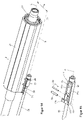
- figure 3 shows in the same perspective as figure 1 a cut-out view, the outer jacket 3 being omitted for a better overview.
- a longitudinal section along the longitudinal axis L is shown in side view.
- the drive unit 51 of the adjustment drive 5 is fixedly connected to the front end of the outer jacket 3 and has a worm wheel 52, which is rotatable about a spindle axis S in bearings 53 and is supported in the longitudinal direction on the drive unit 51, as shown in the longitudinal section of FIG figure 4 is recognizable.
- a worm 55 that can be driven in rotation by an electric servomotor 54 meshes with the worm wheel 52 so that the latter can be driven in rotation about the spindle axis S by the servomotor 54 .
- a threaded spindle 56 which extends on said spindle axis S is connected in a rotationally fixed manner to the worm wheel 52 .
- the threaded spindle 56 is screwed into a spindle nut 57 in a threaded bore 57a, which is secured against rotation about the spindle axis S and supported in the longitudinal direction on the jacket tube 21 of the actuating unit 2, as will be explained in detail further below.
- the threaded spindle 56 has a stop body 560 which limits the movement of the spindle nut 57 on the threaded spindle 56 .
- the threaded spindle 56 rotates and is either screwed into the threaded bore 57a of the spindle nut 57, which thereby telescopes the casing tube 21 and thus the actuating unit 2 forward in the direction of the drive unit 51 in the outer casing 3 - in figure 4 to the left - retracts, or the threaded spindle 56 is unscrewed from the spindle nut 57, so that the actuating unit 2 backwards out of the outer casing 3 - in figure 4 to the right - is driven out.
- the steering spindle 22 has an upper steering spindle part 22a and a lower steering spindle part 22b, which are non-rotatable with one another and telescopically adjustable relative to one another in the longitudinal direction in order to be able to follow the longitudinal adjustment of the steering column 1.
- the spindle axis S is arranged essentially at a distance a parallel to the longitudinal axis L, i.e. the threaded spindle 56 has a radial distance a from the steering spindle 22, and according to the invention is arranged at least in sections within a spindle tunnel 25 within the actuating unit 2.
- Spindle tunnel 25 is formed by an opening that extends longitudinally through jacket tube 21, which is formed separately from opening 26, which also extends longitudinally, in which steering spindle 22 is mounted coaxially on longitudinal axis L, as shown in FIG figure 6 shown cross section BB figure 5 is removable.
- the threaded spindle 56 dips further into the spindle tunnel 25 .
- the threaded spindle 56 is protected in the spindle tunnel 25 in every setting of the steering column 1 .
- the enlarged detail of the cross section in figure 6 shows that the spindle tunnel 25 has a non-circular cross-section, into which the spindle nut 57 is inserted in a form-fitting manner, so that it is secured against rotation about the spindle axis S relative to the jacket tube 21 by the form-fitting connection.
- the spindle nut 57 is secured to the front by a fixing bolt 58 which penetrates the spindle tunnel 25 transversely and is firmly inserted into the casing tube 21 .
- the spindle nut 57 is secured to the rear by means of a predetermined breaking element in the form of a shear pin 59 in the longitudinal direction, which also penetrates the spindle tunnel 25 transversely.
- the spindle nut 57 is therefore fixed between the fixing bolt 58 and the shear pin 59 in normal operation, so that the movement of the spindle nut 57 for telescopic adjustment is transmitted to the control unit 2.
- an energy absorbing device 7 which has an energy absorbing element 71 in the form of an elongated flexible wire 71, which in the Figures 6 to 10 in a first embodiment, and in the Figures 11 to 13 shown in a second embodiment.
- the bending wire 71 can have a circular cross-section or be designed as a bending strip with an angular cross-section, and can be made of steel, for example, as a bent or bent-stamped part.
- the bending wire 71 has a fastening section 71a at its first end, which is adjoined by a first leg 71b, which runs backwards in the longitudinal direction essentially parallel to the longitudinal axis L and which, via a bend 71c of essentially 180°, becomes a second leg 71d running forward counter to the longitudinal direction.
- the fastening section 71a is fastened to the front end of the casing tube 21 on the adjusting unit 2, specifically hooked in a form-fitting manner, as in FIG figure 9 evident.
- the first leg 71b is arranged in a longitudinally extending groove-shaped recess 57b of the spindle nut 57, which forms a guide groove for the bending wire 71, and guided in the longitudinal direction, and passed through the spindle tunnel 25 to the rear, then around a bending anvil formed on the spindle nut 57 57c guided around, and guided forward again with the second leg 57c in a groove-shaped recess 57d between the spindle nut 57 and the spindle tunnel 25.
- the arrangement of the legs 71a and 71b is shown in figure 6 clearly.
- the second end of the bending wire forms a free end with an exposed end portion 71i.
- the groove-shaped recesses 57b and 57d and the bending anvil 57c are preferably formed in one piece on the spindle nut 57, for example by machining or non-machining forming.
- FIGS 7 and 9 12 show perspective views with the spindle tunnel 25 cut open in the longitudinal direction.
- figure 8 is in the same view as in figure 7 the jacket tube 21 omitted for clarity. From this it can be seen how the bending wire 71 is led around the spindle nut 57 within the spindle tunnel 25 .
- the energy absorption device 7 is activated in the event of a crash when an impacting body exerts a high peak force on the steering spindle 22 in a forward direction on the actuating unit 2 .
- the spindle nut 57 which is supported at the front against the threaded spindle 56, is pressed in the longitudinal direction backwards with this great force against the shear pin 59, which breaks when a predetermined predetermined breaking limit force is exceeded, and the movement of the spindle nut 57 within the spindle tunnel 25 relative to the jacket tube 21 releases to the rear.
- the movement of the spindle nut 57 relative to the jacket tube 21 in the event of a crash is figures 7 and 9 indicated with an arrow.
- the jacket tube 21 takes the fastening section 71a of the bending wire 71 with it, so that the first leg 71b is pulled forward relative to the spindle nut 57, guided in the recess 57b, and as a result the second leg 57d is pulled with respect to of the spindle nut 57 is moved backwards and is thereby forced around the bending anvil 57c, so that the bend 71c is continuously moved over the bending wire 71, with continuous kinetic energy for energy absorption in deformation work and to a small extent also heat due to the friction acting between the bending wire 71 and spindle nut 57 is converted, so that controlled braking of the actuating unit 2 relative to the outer shell 3 is effected.
- the bending wire 71 has an end section 71i, which can also be referred to as the free end, with the end section 71i not being fixed and thus moving relative to the spindle nut 57 in the event of a crash.
- the attachment portion 71a moves together with the actuator 2, with the end portion 71i moving both relative to the actuator 2 and relative to the spindle nut 57.
- both the threaded spindle 56 and the energy absorption device 7 are protected with the bending wire 71 and are therefore functionally safe within the actuating unit 2, in the example shown within the spindle tunnel 25.
- FIG Figures 11 to 13 A second embodiment of an energy absorbing device with a bending wire 71 is shown in FIG Figures 11 to 13 shown.
- this has a second bend 71e of approximately 180° following the second leg 71b, which is followed by a third leg 71f which, via a third bend 71g of essentially 180°, leads into a fourth leg 71h passes.
- Legs 71b and 71f point in the longitudinal direction, legs 71d and 71h point in the opposite direction.
- the exposed end section 71i forms the free end of the bending wire 71.
- the spindle nut 57 has a guide device comprising recesses 57b, 57d, 57f and 57h corresponding to the course of the legs 71b, 71d, 71f and 71h of the bending wire 71, and a second bending anvil 57e, around which the bend 71e is guided, and a third bending anvil 57g, around which the bend 71g is guided.
- the bending wire 71 is as in figure 11 shown arranged in the guiding device of the spindle nut 57 .
- the bending wire 71 is guided through the recesses 57b, 57d, 57f, 57h, with deformation work being carried out in each case pulled around the total of three bending anvils 57c, 57g and 57e until after the crash, as in figure 12 shown stretched in the longitudinal direction.
- a relatively long bending wire 71 can be used, which is wound several times around the spindle nut 57 in the guide device and, in the event of a crash, can absorb kinetic energy evenly over a long deformation path.
- the spindle nut 57 of the second embodiment has a bore 570 that is orthogonal is arranged to the spindle axis S.
- the shear pin 59 which is coupled to the control unit, can be inserted in this bore.
- the bending wire 71 has an end section 71i, which can also be referred to as the free end, with the end section 71i not being fixed and thus moving relative to the spindle nut 57 in the event of a crash.
- the fastening section 71a moves together with the actuating unit 2, with the end section 71i moving both relative to the actuating unit 2 and relative to the spindle nut 57.
- the bending anvils 57c, 57g and 57e acting as forming elements according to the invention and the groove-shaped recesses 57b, 57d, 57f and 57h serving as guide elements for the bending wire 71 can preferably be formed in one piece with the spindle nut 57, for example by machining or non-machining.
- the jacket tube 21 and/or the outer jacket 3 can each be designed as an extruded profile, for example made of an aluminum or magnesium alloy.
- FIG 14 is an alternative embodiment of the actuator 2 in the same view as in FIG figure 7 shown. This differs in that the casing tube 21 does not have a spindle tunnel 25, but rather the threaded spindle 56 is arranged in an exposed manner laterally outside of the casing tube 21, and the spindle nut 57 is also attached to the casing tube 21 on the outside.
- the function of the adjustment drive 5 according to the invention and the energy absorption device 7 is otherwise identical.
- rolling element raceways 27 can be formed on the outside of the casing tube 21, in the example shown three rolling element raceways 27 are distributed over the circumference, which extend over the entire length, and are integrally formed in the casing tube 21 be able.
- Corresponding rolling element raceways 31 are formed radially opposite these on the inside in the outer jacket 3 .
- Between the rolling element raceways 27 and 31 are as rolling elements 8 rollers rotatably arranged in a roller cage 81, which can roll to form a smooth linear bearing when adjusting the steering column 1 in the longitudinal direction.
- FIG 15 is a spindle nut 57 with an energy absorption device in a third embodiment in a view similar to that in FIG figure 11 shown.
- This has a bending wire 71 with a first leg 71b and a second leg 71d.
- the first leg 71b running backwards in the longitudinal direction has a hook-shaped fastening section 71a at the front at its free end and transitions via a bend 71c of essentially 180° into the second leg 71d running forwards counter to the longitudinal direction.
- the bend 71c is bent freely, ie it is not as in FIG figure 11 guided around a bending anvil 57c.
- the bending wire 71 has a rectangular cross section.
- the bending wire 71 is hooked onto the jacket tube 21 with the fastening section 71a, as is the case for the embodiment in Figures 10 to 12 is described.
- the bending wire 71 is continuously bent, with the bend 71c, which is free in this embodiment, moving in the longitudinal direction relative to the spindle nut 57, as shown in FIG figure 15 indicated with the arrow.
- a fourth embodiment of an energy absorption device 7 is shown, the view from FIG figure 16 the view of figure 7 is equivalent to, figure 17 the view of figure 11 or 14 , figure 18 the view of figure 13 , and figure 19 the situation after a crash is analogous to figure 12 indicates.
- the same reference symbols are used for components that have the same effect.
- the spindle nut 57 has, similar to that in figure 12 shown embodiment the groove-shaped recesses 57b, 57d and 57f, in the course of which the bending anvils 57c and 57e are arranged.
- a guide device is formed, through which the bending wire 71 is pulled in the event of a crash and, as a result of the resulting plastic deformation, continuously absorbs kinetic energy during bending.
- the bending wire 71 has a hook-shaped fastening section 71a, which is adjoined by a first leg 71b running backwards in the longitudinal direction, which, via a bend 71c of essentially 180°, becomes a second leg 71d running forwards in the opposite direction to the longitudinal direction transforms.
- the fastening section 71a is fastened to the front end of the jacket tube 21, namely hooked in a form-fitting manner, as in FIG figure 9 .
- the first leg 71b is arranged in the longitudinally extending groove-shaped recess 57b of the spindle nut 57 and in guided through the spindle tunnel 25 to the rear, then guided around the bending anvil 57c in the region of its bend 71c.
- the second leg 57c adjoining the bend 71c is arranged in the groove-shaped recess 57d and guided around the second bending anvil 57e with the bend 71e and merges into the third leg 71f.
- the bending wire 71 to form a supply coil 71k is helically wound around the spindle axis S on a substantially cylindrical winding section 57k, which is coaxially formed with the spindle axis S and faces backwards on the spindle nut 57 coiled.
- the supply coil 71k is designed as a single-layer, flat coil, which preferably has a plurality of axially consecutive turns.
- the bending wire 71 is pulled from the supply coil 71k in the axial direction into the recess 57 and is pulled through the recesses 57f, 57d and 57b around the two bending anvils 57e and 57c in between, performing the respective deformation work, until after the crash it in figure 19 shown stretched between the attachment portion 71a and the spindle nut 57 in the longitudinal direction.
- a relatively long bending wire 71 can be used, which can be stored in several turns in the supply coil 71k. During unwinding from the supply reel in the event of a crash, the bending strip 71 continuously bent around the bending anvils 57e and 57c can absorb kinetic energy evenly over a long deformation path.
- a particular advantage of this arrangement is that the supply spool 71k is pulled apart and unwound via the leg 71f essentially in the axial direction with respect to the spindle axis S.
- the supply reel 71k can be continuously unwound from the winding section 57k until the figure 19 shown state is reached, which is analogous to figure 12 is reached.
- the axial direction payout allows the bending wire stored on the supply spool 71k to be paid out smoothly, and the turns are prevented from being tightened like a loop on the winding portion 57, which could increase the force required for payout.
Landscapes
- Engineering & Computer Science (AREA)
- Chemical & Material Sciences (AREA)
- Combustion & Propulsion (AREA)
- Transportation (AREA)
- Mechanical Engineering (AREA)
- Steering Controls (AREA)
Claims (8)
- Colonne de direction (1) réglable par moteur pour un véhicule automobile, comprenant une enveloppe extérieure (3), qui est maintenue par une unité de support (4) pouvant être disposée sur une carrosserie de véhicule et dans laquelle une unité de réglage (2) est logée de manière réglable dans la direction longitudinale, dans laquelle un arbre de direction (22) est monté coaxialement dans un tube d'enveloppe (21) de manière à pouvoir tourner autour d'un axe longitudinal (L), un entraînement de réglage (5) et un appareil d'absorption d'énergie (7) étant agencés entre l'enveloppe extérieure (3) et l'unité de réglage (2), l'entraînement de réglage (5) présentant un mécanisme à broche avec une broche filetée (56), qui s'engage dans un écrou de broche (57) en pouvant être entraînée en rotation par un servomoteur électrique (54), et l'appareil d'absorption d'énergie (7) comprenant au moins un élément d'absorption d'énergie (71) agencé au moins indirectement entre l'écrou de broche (57) et l'unité de réglage (2),
caractérisée en ce que
l'écrou de broche (57) ou la broche filetée (56) présente au moins un élément de déformation (57c, 57e, 57g), qui est en prise active avec l'élément d'absorption d'énergie (71) et par lequel l'élément d'absorption d'énergie (71) peut être déformé plastiquement. - Colonne de direction selon la revendication 1, caractérisée en ce que l'élément de déformation (57c, 57e, 57g) est configuré de manière intégrée avec l'écrou de broche (57) ou la broche filetée (56).
- Colonne de direction selon l'une quelconque des revendications précédentes, caractérisée en ce que l'élément d'absorption d'énergie (71) est configuré sous la forme d'un fil de flexion allongé (71) ayant une longueur, qui peut être déplacée par rapport à l'élément de déformation (57c, 57e, 57g) et qui peut être déformée par l'élément de déformation (57c, 57e, 57g) au moins partiellement le long de sa longueur.
- Colonne de direction selon la revendication 3, caractérisée en ce que l'élément de déformation (57c, 57e, 57g) présente au moins une enclume de flexion (57c, 57e, 57g) autour de laquelle le fil de flexion (71) est replié transversalement à l'axe longitudinal (L).
- Colonne de direction selon la revendication 3, caractérisée en ce que le fil de flexion (71) a une première extrémité (71a) reliée à l'unité de réglage (2), et une deuxième extrémité libre (71 i).
- Colonne de direction selon l'une quelconque des revendications précédentes, caractérisée en ce que l'écrou de broche (57) ou la broche filetée (56) présente au moins un élément de guidage (57b, 57d, 57f, 57h).
- Colonne de direction selon l'une quelconque des revendications précédentes, caractérisée en ce qu'un élément destiné à la rupture (59) est agencé entre l'écrou de broche (57) ou la broche filetée (56) et l'unité de réglage (2).
- Colonne de direction selon l'une quelconque des revendications précédentes, caractérisée en ce que l'arbre de direction (22) est couplé à un mécanisme de direction ou à un actionneur à rétroaction.
Applications Claiming Priority (2)
| Application Number | Priority Date | Filing Date | Title |
|---|---|---|---|
| DE102017223470.9A DE102017223470A1 (de) | 2017-12-20 | 2017-12-20 | Motorisch verstellbare Lenksäule für ein Kraftfahrzeug |
| PCT/EP2018/084787 WO2019121331A1 (fr) | 2017-12-20 | 2018-12-13 | Colonne de direction à réglage motorisé pour véhicule à moteur |
Publications (2)
| Publication Number | Publication Date |
|---|---|
| EP3727995A1 EP3727995A1 (fr) | 2020-10-28 |
| EP3727995B1 true EP3727995B1 (fr) | 2022-04-27 |
Family
ID=64949234
Family Applications (1)
| Application Number | Title | Priority Date | Filing Date |
|---|---|---|---|
| EP18829772.5A Active EP3727995B1 (fr) | 2017-12-20 | 2018-12-13 | Colonne de direction à réglage motorisé pour véhicule à moteur |
Country Status (5)
| Country | Link |
|---|---|
| US (1) | US11247714B2 (fr) |
| EP (1) | EP3727995B1 (fr) |
| CN (1) | CN111511628B (fr) |
| DE (1) | DE102017223470A1 (fr) |
| WO (1) | WO2019121331A1 (fr) |
Families Citing this family (5)
| Publication number | Priority date | Publication date | Assignee | Title |
|---|---|---|---|---|
| DE102015216715A1 (de) * | 2015-09-01 | 2017-03-02 | Thyssenkrupp Ag | Verstellbare Lenksäule für Kraftfahrzeuge mit Energieabsorber für den Fahrzeugcrash |
| DE102017120669B4 (de) * | 2017-09-07 | 2025-03-20 | Zf Automotive Germany Gmbh | Lenksäulenbaugruppe für ein Kraftfahrzeug sowie Lenkungssystem |
| DE102019212435A1 (de) * | 2019-08-20 | 2021-02-25 | Thyssenkrupp Ag | Lenksäule für ein Kraftfahrzeug |
| EP4282734B1 (fr) | 2022-05-23 | 2025-01-08 | Volvo Truck Corporation | Ensemble roue de direction pour un véhicule |
| BE1029836B1 (de) * | 2022-11-03 | 2024-05-30 | Thyssenkrupp Presta Ag | Lenksäule für ein Kraftfahrzeug |
Family Cites Families (23)
| Publication number | Priority date | Publication date | Assignee | Title |
|---|---|---|---|---|
| US2769351A (en) | 1955-06-13 | 1956-11-06 | Byron A Serfling | Adjustable steering post |
| US4602520A (en) | 1983-06-23 | 1986-07-29 | Aisin Seiki Kabushiki Kaisha | Telescopic steering column assembly |
| DE4413798C2 (de) * | 1994-03-18 | 1996-09-12 | Porsche Ag | Verstellbare Lenkeinrichtung |
| DE19524196C1 (de) | 1995-07-03 | 1996-11-14 | Daimler Benz Ag | Längsverstellvorrichtung an einem Mantelrohrteleskop einer Lenkspindel in einem Kraftfahrzeug |
| JP3612971B2 (ja) * | 1997-12-03 | 2005-01-26 | 日本精工株式会社 | 衝撃吸収式ステアリングコラム装置 |
| DE19757322A1 (de) * | 1997-12-23 | 1999-06-24 | Mannesmann Vdo Ag | Zur Lagerung an einem Karosserieteil eines Kraftfahrzeuges vorgesehene Lenkspindel |
| DE19812179C1 (de) * | 1998-03-19 | 1999-08-19 | Daimler Chrysler Ag | Lenksäulenanordnung für ein Kraftfahrzeug |
| DE10259596B3 (de) * | 2002-12-19 | 2004-05-13 | Daimlerchrysler Ag | Lenksäulenanordnung |
| JP2007030527A (ja) | 2005-02-17 | 2007-02-08 | Nsk Ltd | ステアリングホイールの電動式位置調節装置 |
| EP1880917A1 (fr) | 2006-03-03 | 2008-01-23 | NSK Ltd. | Dispositif de direction |
| JP5369537B2 (ja) * | 2008-08-08 | 2013-12-18 | アイシン精機株式会社 | エネルギー吸収ステアリングコラム |
| DE102011083190A1 (de) | 2011-09-15 | 2013-03-21 | Zf Lenksysteme Nacam Gmbh | Kraftfahrzeuglenksäule mit Energieabsorber |
| US8899622B2 (en) * | 2012-03-09 | 2014-12-02 | Nsk Americas, Inc. | Internally collapsible steering column assembly |
| US9663136B2 (en) * | 2014-02-20 | 2017-05-30 | Steering Solutions Ip Holding Corporation | Steering column having anti-rotation feature |
| DE102015207230B3 (de) * | 2015-04-21 | 2016-03-24 | Thyssenkrupp Ag | Lenksäule für ein Kraftfahrzeug |
| DE102015224602B4 (de) | 2015-12-08 | 2023-05-04 | Thyssenkrupp Ag | Lenksäule für eine steer-by-wire-Lenkeinrichtung |
| JP6609211B2 (ja) * | 2016-03-28 | 2019-11-20 | 富士機工株式会社 | ステアリングコラム装置 |
| JP6621359B2 (ja) * | 2016-03-31 | 2019-12-18 | 富士機工株式会社 | ステアリングコラム装置 |
| DE102016205378B3 (de) | 2016-03-31 | 2017-05-11 | Thyssenkrupp Ag | Lenksäule für ein Kraftfahrzeug |
| KR101814520B1 (ko) * | 2016-04-08 | 2018-01-11 | 남양공업주식회사 | 차량의 충격 흡수식 스티어링 장치 |
| KR102274121B1 (ko) * | 2017-04-03 | 2021-07-06 | 현대자동차주식회사 | 자동차용 전동식 스티어링 컬럼 장치 |
| DE102017207561A1 (de) | 2017-05-05 | 2017-07-06 | Thyssenkrupp Ag | Lenksäule für ein Kraftfahrzeug und Verfahren zur Herstellung einer Lenksäule |
| DE102017223469A1 (de) * | 2017-12-20 | 2019-06-27 | Thyssenkrupp Ag | Motorisch verstellbare Lenksäule für ein Kraftfahrzeug |
-
2017
- 2017-12-20 DE DE102017223470.9A patent/DE102017223470A1/de not_active Withdrawn
-
2018
- 2018-12-13 WO PCT/EP2018/084787 patent/WO2019121331A1/fr not_active Ceased
- 2018-12-13 US US16/768,718 patent/US11247714B2/en active Active
- 2018-12-13 CN CN201880081954.6A patent/CN111511628B/zh active Active
- 2018-12-13 EP EP18829772.5A patent/EP3727995B1/fr active Active
Also Published As
| Publication number | Publication date |
|---|---|
| CN111511628A (zh) | 2020-08-07 |
| EP3727995A1 (fr) | 2020-10-28 |
| DE102017223470A1 (de) | 2019-06-27 |
| WO2019121331A1 (fr) | 2019-06-27 |
| US20210009189A1 (en) | 2021-01-14 |
| US11247714B2 (en) | 2022-02-15 |
| CN111511628B (zh) | 2022-07-22 |
Similar Documents
| Publication | Publication Date | Title |
|---|---|---|
| EP3727994B1 (fr) | Colonne de direction à réglage motorisé pour véhicule à moteur | |
| EP3727995B1 (fr) | Colonne de direction à réglage motorisé pour véhicule à moteur | |
| EP3829956B1 (fr) | Mécanisme de réglage destiné à une colonne de direction et colonne de direction pour véhicule automobile | |
| DE10203917C1 (de) | Lenksäulenanordnung für ein Kraftfahrzeug | |
| EP0943525B1 (fr) | Colonne de direction d'un véhicule automobile | |
| EP3386837B1 (fr) | Colonne de direction pour système de direction à commande électrique | |
| EP3853107B1 (fr) | Colonne de direction et système de direction à commande par câble | |
| EP4017781B1 (fr) | Colonne de direction pour un véhicule automobile | |
| EP3938268B1 (fr) | Entraînement de réglage pour une colonne de direction et colonne de direction pour un véhicule automobile | |
| EP3870495B1 (fr) | Colonne de direction pour un véhicule automobile | |
| EP4222042A1 (fr) | Colonne de direction pour un véhicule automobile | |
| EP3752406B1 (fr) | Colonne de direction pour un véhicule automobile | |
| EP3436329B1 (fr) | Colonne de direction pour véhicule automobile | |
| EP3883839B1 (fr) | Colonne de direction pour véhicule autmobile | |
| EP2037067B1 (fr) | Dispositif d'entraînement pour une porte de véhicule | |
| EP4279357B1 (fr) | Système de direction pour un véhicule automobile | |
| WO2024179629A1 (fr) | Unité de commande à longueur réglable | |
| DE102022119870B4 (de) | Energie-Absorptionsbaugruppe und Sicherheitslenksäule eines Kraftfahrzeugs | |
| BE1030038B1 (de) | Steer-by-Wire-Lenksäule für ein Kraftfahrzeug | |
| WO2025045790A1 (fr) | Colonne de direction pour un véhicule motorisé et élément d'absorption d'énergie pour une colonne de direction |
Legal Events
| Date | Code | Title | Description |
|---|---|---|---|
| STAA | Information on the status of an ep patent application or granted ep patent |
Free format text: STATUS: UNKNOWN |
|
| STAA | Information on the status of an ep patent application or granted ep patent |
Free format text: STATUS: THE INTERNATIONAL PUBLICATION HAS BEEN MADE |
|
| PUAI | Public reference made under article 153(3) epc to a published international application that has entered the european phase |
Free format text: ORIGINAL CODE: 0009012 |
|
| STAA | Information on the status of an ep patent application or granted ep patent |
Free format text: STATUS: REQUEST FOR EXAMINATION WAS MADE |
|
| 17P | Request for examination filed |
Effective date: 20200720 |
|
| AK | Designated contracting states |
Kind code of ref document: A1 Designated state(s): AL AT BE BG CH CY CZ DE DK EE ES FI FR GB GR HR HU IE IS IT LI LT LU LV MC MK MT NL NO PL PT RO RS SE SI SK SM TR |
|
| AX | Request for extension of the european patent |
Extension state: BA ME |
|
| RAP1 | Party data changed (applicant data changed or rights of an application transferred) |
Owner name: THYSSENKRUPP PRESTA AG Owner name: THYSSENKRUPP AG |
|
| DAV | Request for validation of the european patent (deleted) | ||
| DAX | Request for extension of the european patent (deleted) | ||
| GRAP | Despatch of communication of intention to grant a patent |
Free format text: ORIGINAL CODE: EPIDOSNIGR1 |
|
| STAA | Information on the status of an ep patent application or granted ep patent |
Free format text: STATUS: GRANT OF PATENT IS INTENDED |
|
| INTG | Intention to grant announced |
Effective date: 20211215 |
|
| GRAS | Grant fee paid |
Free format text: ORIGINAL CODE: EPIDOSNIGR3 |
|
| GRAA | (expected) grant |
Free format text: ORIGINAL CODE: 0009210 |
|
| STAA | Information on the status of an ep patent application or granted ep patent |
Free format text: STATUS: THE PATENT HAS BEEN GRANTED |
|
| AK | Designated contracting states |
Kind code of ref document: B1 Designated state(s): AL AT BE BG CH CY CZ DE DK EE ES FI FR GB GR HR HU IE IS IT LI LT LU LV MC MK MT NL NO PL PT RO RS SE SI SK SM TR |
|
| REG | Reference to a national code |
Ref country code: GB Ref legal event code: FG4D Free format text: NOT ENGLISH |
|
| REG | Reference to a national code |
Ref country code: CH Ref legal event code: EP |
|
| REG | Reference to a national code |
Ref country code: AT Ref legal event code: REF Ref document number: 1486747 Country of ref document: AT Kind code of ref document: T Effective date: 20220515 |
|
| REG | Reference to a national code |
Ref country code: DE Ref legal event code: R096 Ref document number: 502018009528 Country of ref document: DE |
|
| REG | Reference to a national code |
Ref country code: IE Ref legal event code: FG4D Free format text: LANGUAGE OF EP DOCUMENT: GERMAN |
|
| REG | Reference to a national code |
Ref country code: LT Ref legal event code: MG9D |
|
| REG | Reference to a national code |
Ref country code: NL Ref legal event code: MP Effective date: 20220427 |
|
| REG | Reference to a national code |
Ref country code: DE Ref legal event code: R084 Ref document number: 502018009528 Country of ref document: DE |
|
| PG25 | Lapsed in a contracting state [announced via postgrant information from national office to epo] |
Ref country code: NL Free format text: LAPSE BECAUSE OF FAILURE TO SUBMIT A TRANSLATION OF THE DESCRIPTION OR TO PAY THE FEE WITHIN THE PRESCRIBED TIME-LIMIT Effective date: 20220427 |
|
| PG25 | Lapsed in a contracting state [announced via postgrant information from national office to epo] |
Ref country code: SE Free format text: LAPSE BECAUSE OF FAILURE TO SUBMIT A TRANSLATION OF THE DESCRIPTION OR TO PAY THE FEE WITHIN THE PRESCRIBED TIME-LIMIT Effective date: 20220427 Ref country code: PT Free format text: LAPSE BECAUSE OF FAILURE TO SUBMIT A TRANSLATION OF THE DESCRIPTION OR TO PAY THE FEE WITHIN THE PRESCRIBED TIME-LIMIT Effective date: 20220829 Ref country code: NO Free format text: LAPSE BECAUSE OF FAILURE TO SUBMIT A TRANSLATION OF THE DESCRIPTION OR TO PAY THE FEE WITHIN THE PRESCRIBED TIME-LIMIT Effective date: 20220727 Ref country code: LT Free format text: LAPSE BECAUSE OF FAILURE TO SUBMIT A TRANSLATION OF THE DESCRIPTION OR TO PAY THE FEE WITHIN THE PRESCRIBED TIME-LIMIT Effective date: 20220427 Ref country code: HR Free format text: LAPSE BECAUSE OF FAILURE TO SUBMIT A TRANSLATION OF THE DESCRIPTION OR TO PAY THE FEE WITHIN THE PRESCRIBED TIME-LIMIT Effective date: 20220427 Ref country code: GR Free format text: LAPSE BECAUSE OF FAILURE TO SUBMIT A TRANSLATION OF THE DESCRIPTION OR TO PAY THE FEE WITHIN THE PRESCRIBED TIME-LIMIT Effective date: 20220728 Ref country code: FI Free format text: LAPSE BECAUSE OF FAILURE TO SUBMIT A TRANSLATION OF THE DESCRIPTION OR TO PAY THE FEE WITHIN THE PRESCRIBED TIME-LIMIT Effective date: 20220427 Ref country code: BG Free format text: LAPSE BECAUSE OF FAILURE TO SUBMIT A TRANSLATION OF THE DESCRIPTION OR TO PAY THE FEE WITHIN THE PRESCRIBED TIME-LIMIT Effective date: 20220727 |
|
| PG25 | Lapsed in a contracting state [announced via postgrant information from national office to epo] |
Ref country code: RS Free format text: LAPSE BECAUSE OF FAILURE TO SUBMIT A TRANSLATION OF THE DESCRIPTION OR TO PAY THE FEE WITHIN THE PRESCRIBED TIME-LIMIT Effective date: 20220427 Ref country code: PL Free format text: LAPSE BECAUSE OF FAILURE TO SUBMIT A TRANSLATION OF THE DESCRIPTION OR TO PAY THE FEE WITHIN THE PRESCRIBED TIME-LIMIT Effective date: 20220427 Ref country code: LV Free format text: LAPSE BECAUSE OF FAILURE TO SUBMIT A TRANSLATION OF THE DESCRIPTION OR TO PAY THE FEE WITHIN THE PRESCRIBED TIME-LIMIT Effective date: 20220427 Ref country code: IS Free format text: LAPSE BECAUSE OF FAILURE TO SUBMIT A TRANSLATION OF THE DESCRIPTION OR TO PAY THE FEE WITHIN THE PRESCRIBED TIME-LIMIT Effective date: 20220827 |
|
| REG | Reference to a national code |
Ref country code: DE Ref legal event code: R097 Ref document number: 502018009528 Country of ref document: DE |
|
| PG25 | Lapsed in a contracting state [announced via postgrant information from national office to epo] |
Ref country code: SM Free format text: LAPSE BECAUSE OF FAILURE TO SUBMIT A TRANSLATION OF THE DESCRIPTION OR TO PAY THE FEE WITHIN THE PRESCRIBED TIME-LIMIT Effective date: 20220427 Ref country code: SK Free format text: LAPSE BECAUSE OF FAILURE TO SUBMIT A TRANSLATION OF THE DESCRIPTION OR TO PAY THE FEE WITHIN THE PRESCRIBED TIME-LIMIT Effective date: 20220427 Ref country code: RO Free format text: LAPSE BECAUSE OF FAILURE TO SUBMIT A TRANSLATION OF THE DESCRIPTION OR TO PAY THE FEE WITHIN THE PRESCRIBED TIME-LIMIT Effective date: 20220427 Ref country code: ES Free format text: LAPSE BECAUSE OF FAILURE TO SUBMIT A TRANSLATION OF THE DESCRIPTION OR TO PAY THE FEE WITHIN THE PRESCRIBED TIME-LIMIT Effective date: 20220427 Ref country code: EE Free format text: LAPSE BECAUSE OF FAILURE TO SUBMIT A TRANSLATION OF THE DESCRIPTION OR TO PAY THE FEE WITHIN THE PRESCRIBED TIME-LIMIT Effective date: 20220427 Ref country code: DK Free format text: LAPSE BECAUSE OF FAILURE TO SUBMIT A TRANSLATION OF THE DESCRIPTION OR TO PAY THE FEE WITHIN THE PRESCRIBED TIME-LIMIT Effective date: 20220427 Ref country code: CZ Free format text: LAPSE BECAUSE OF FAILURE TO SUBMIT A TRANSLATION OF THE DESCRIPTION OR TO PAY THE FEE WITHIN THE PRESCRIBED TIME-LIMIT Effective date: 20220427 |
|
| PLBE | No opposition filed within time limit |
Free format text: ORIGINAL CODE: 0009261 |
|
| STAA | Information on the status of an ep patent application or granted ep patent |
Free format text: STATUS: NO OPPOSITION FILED WITHIN TIME LIMIT |
|
| PG25 | Lapsed in a contracting state [announced via postgrant information from national office to epo] |
Ref country code: AL Free format text: LAPSE BECAUSE OF FAILURE TO SUBMIT A TRANSLATION OF THE DESCRIPTION OR TO PAY THE FEE WITHIN THE PRESCRIBED TIME-LIMIT Effective date: 20220427 |
|
| 26N | No opposition filed |
Effective date: 20230130 |
|
| PG25 | Lapsed in a contracting state [announced via postgrant information from national office to epo] |
Ref country code: SI Free format text: LAPSE BECAUSE OF FAILURE TO SUBMIT A TRANSLATION OF THE DESCRIPTION OR TO PAY THE FEE WITHIN THE PRESCRIBED TIME-LIMIT Effective date: 20220427 |
|
| REG | Reference to a national code |
Ref country code: CH Ref legal event code: PL |
|
| REG | Reference to a national code |
Ref country code: BE Ref legal event code: MM Effective date: 20221231 |
|
| PG25 | Lapsed in a contracting state [announced via postgrant information from national office to epo] |
Ref country code: LU Free format text: LAPSE BECAUSE OF NON-PAYMENT OF DUE FEES Effective date: 20221213 |
|
| PG25 | Lapsed in a contracting state [announced via postgrant information from national office to epo] |
Ref country code: LI Free format text: LAPSE BECAUSE OF NON-PAYMENT OF DUE FEES Effective date: 20221231 Ref country code: IE Free format text: LAPSE BECAUSE OF NON-PAYMENT OF DUE FEES Effective date: 20221213 Ref country code: CH Free format text: LAPSE BECAUSE OF NON-PAYMENT OF DUE FEES Effective date: 20221231 |
|
| PG25 | Lapsed in a contracting state [announced via postgrant information from national office to epo] |
Ref country code: BE Free format text: LAPSE BECAUSE OF NON-PAYMENT OF DUE FEES Effective date: 20221231 |
|
| PG25 | Lapsed in a contracting state [announced via postgrant information from national office to epo] |
Ref country code: IT Free format text: LAPSE BECAUSE OF FAILURE TO SUBMIT A TRANSLATION OF THE DESCRIPTION OR TO PAY THE FEE WITHIN THE PRESCRIBED TIME-LIMIT Effective date: 20220427 |
|
| PG25 | Lapsed in a contracting state [announced via postgrant information from national office to epo] |
Ref country code: CY Free format text: LAPSE BECAUSE OF FAILURE TO SUBMIT A TRANSLATION OF THE DESCRIPTION OR TO PAY THE FEE WITHIN THE PRESCRIBED TIME-LIMIT Effective date: 20220427 |
|
| PG25 | Lapsed in a contracting state [announced via postgrant information from national office to epo] |
Ref country code: MK Free format text: LAPSE BECAUSE OF FAILURE TO SUBMIT A TRANSLATION OF THE DESCRIPTION OR TO PAY THE FEE WITHIN THE PRESCRIBED TIME-LIMIT Effective date: 20220427 Ref country code: HU Free format text: LAPSE BECAUSE OF FAILURE TO SUBMIT A TRANSLATION OF THE DESCRIPTION OR TO PAY THE FEE WITHIN THE PRESCRIBED TIME-LIMIT; INVALID AB INITIO Effective date: 20181213 |
|
| PG25 | Lapsed in a contracting state [announced via postgrant information from national office to epo] |
Ref country code: MC Free format text: LAPSE BECAUSE OF FAILURE TO SUBMIT A TRANSLATION OF THE DESCRIPTION OR TO PAY THE FEE WITHIN THE PRESCRIBED TIME-LIMIT Effective date: 20220427 |
|
| PG25 | Lapsed in a contracting state [announced via postgrant information from national office to epo] |
Ref country code: MC Free format text: LAPSE BECAUSE OF FAILURE TO SUBMIT A TRANSLATION OF THE DESCRIPTION OR TO PAY THE FEE WITHIN THE PRESCRIBED TIME-LIMIT Effective date: 20220427 |
|
| PG25 | Lapsed in a contracting state [announced via postgrant information from national office to epo] |
Ref country code: MT Free format text: LAPSE BECAUSE OF FAILURE TO SUBMIT A TRANSLATION OF THE DESCRIPTION OR TO PAY THE FEE WITHIN THE PRESCRIBED TIME-LIMIT Effective date: 20220427 |
|
| PG25 | Lapsed in a contracting state [announced via postgrant information from national office to epo] |
Ref country code: BG Free format text: LAPSE BECAUSE OF FAILURE TO SUBMIT A TRANSLATION OF THE DESCRIPTION OR TO PAY THE FEE WITHIN THE PRESCRIBED TIME-LIMIT Effective date: 20220427 |
|
| PG25 | Lapsed in a contracting state [announced via postgrant information from national office to epo] |
Ref country code: BG Free format text: LAPSE BECAUSE OF FAILURE TO SUBMIT A TRANSLATION OF THE DESCRIPTION OR TO PAY THE FEE WITHIN THE PRESCRIBED TIME-LIMIT Effective date: 20220427 |
|
| REG | Reference to a national code |
Ref country code: AT Ref legal event code: MM01 Ref document number: 1486747 Country of ref document: AT Kind code of ref document: T Effective date: 20231213 |
|
| PG25 | Lapsed in a contracting state [announced via postgrant information from national office to epo] |
Ref country code: AT Free format text: LAPSE BECAUSE OF NON-PAYMENT OF DUE FEES Effective date: 20231213 |
|
| PG25 | Lapsed in a contracting state [announced via postgrant information from national office to epo] |
Ref country code: TR Free format text: LAPSE BECAUSE OF FAILURE TO SUBMIT A TRANSLATION OF THE DESCRIPTION OR TO PAY THE FEE WITHIN THE PRESCRIBED TIME-LIMIT Effective date: 20220427 |
|
| PGFP | Annual fee paid to national office [announced via postgrant information from national office to epo] |
Ref country code: DE Payment date: 20251211 Year of fee payment: 8 |
|
| PGFP | Annual fee paid to national office [announced via postgrant information from national office to epo] |
Ref country code: GB Payment date: 20251219 Year of fee payment: 8 |
|
| PGFP | Annual fee paid to national office [announced via postgrant information from national office to epo] |
Ref country code: FR Payment date: 20251229 Year of fee payment: 8 |
|
| PGFP | Annual fee paid to national office [announced via postgrant information from national office to epo] |
Ref country code: AT Payment date: 20260410 Year of fee payment: 5 |