EP3736227A1 - Closing system for a container - Google Patents
Closing system for a container Download PDFInfo
- Publication number
- EP3736227A1 EP3736227A1 EP20173676.6A EP20173676A EP3736227A1 EP 3736227 A1 EP3736227 A1 EP 3736227A1 EP 20173676 A EP20173676 A EP 20173676A EP 3736227 A1 EP3736227 A1 EP 3736227A1
- Authority
- EP
- European Patent Office
- Prior art keywords
- closing system
- metal
- cap
- casing body
- bottle
- Prior art date
- Legal status (The legal status is an assumption and is not a legal conclusion. Google has not performed a legal analysis and makes no representation as to the accuracy of the status listed.)
- Withdrawn
Links
- 229910052751 metal Inorganic materials 0.000 claims abstract description 33
- 239000002184 metal Substances 0.000 claims abstract description 33
- 239000002304 perfume Substances 0.000 claims abstract description 20
- 230000008878 coupling Effects 0.000 claims abstract description 10
- 238000010168 coupling process Methods 0.000 claims abstract description 10
- 238000005859 coupling reaction Methods 0.000 claims abstract description 10
- 238000005253 cladding Methods 0.000 claims description 19
- 239000004411 aluminium Substances 0.000 claims description 7
- 229910052782 aluminium Inorganic materials 0.000 claims description 7
- XAGFODPZIPBFFR-UHFFFAOYSA-N aluminium Chemical compound [Al] XAGFODPZIPBFFR-UHFFFAOYSA-N 0.000 claims description 7
- XEEYBQQBJWHFJM-UHFFFAOYSA-N Iron Chemical compound [Fe] XEEYBQQBJWHFJM-UHFFFAOYSA-N 0.000 claims description 4
- 239000000463 material Substances 0.000 claims description 4
- 229910001092 metal group alloy Inorganic materials 0.000 claims description 4
- 229910000838 Al alloy Inorganic materials 0.000 claims description 2
- 229910001369 Brass Inorganic materials 0.000 claims description 2
- RYGMFSIKBFXOCR-UHFFFAOYSA-N Copper Chemical compound [Cu] RYGMFSIKBFXOCR-UHFFFAOYSA-N 0.000 claims description 2
- FYYHWMGAXLPEAU-UHFFFAOYSA-N Magnesium Chemical compound [Mg] FYYHWMGAXLPEAU-UHFFFAOYSA-N 0.000 claims description 2
- HCHKCACWOHOZIP-UHFFFAOYSA-N Zinc Chemical compound [Zn] HCHKCACWOHOZIP-UHFFFAOYSA-N 0.000 claims description 2
- 239000010951 brass Substances 0.000 claims description 2
- 229910052802 copper Inorganic materials 0.000 claims description 2
- 239000010949 copper Substances 0.000 claims description 2
- 229910052742 iron Inorganic materials 0.000 claims description 2
- 239000011777 magnesium Substances 0.000 claims description 2
- 229910052749 magnesium Inorganic materials 0.000 claims description 2
- 239000011701 zinc Substances 0.000 claims description 2
- 229910052725 zinc Inorganic materials 0.000 claims description 2
- 230000008602 contraction Effects 0.000 claims 1
- 230000003993 interaction Effects 0.000 claims 1
- 229920003023 plastic Polymers 0.000 description 7
- 239000004033 plastic Substances 0.000 description 7
- 239000007769 metal material Substances 0.000 description 6
- 230000006870 function Effects 0.000 description 4
- 239000002537 cosmetic Substances 0.000 description 3
- 230000007246 mechanism Effects 0.000 description 3
- 239000007921 spray Substances 0.000 description 3
- 230000035807 sensation Effects 0.000 description 2
- 239000000243 solution Substances 0.000 description 2
- 238000007792 addition Methods 0.000 description 1
- 238000004026 adhesive bonding Methods 0.000 description 1
- 238000010586 diagram Methods 0.000 description 1
- 239000011521 glass Substances 0.000 description 1
- 230000006872 improvement Effects 0.000 description 1
- 238000002347 injection Methods 0.000 description 1
- 239000007924 injection Substances 0.000 description 1
- 150000002739 metals Chemical class 0.000 description 1
- 230000004048 modification Effects 0.000 description 1
- 238000012986 modification Methods 0.000 description 1
- 238000004806 packaging method and process Methods 0.000 description 1
- 230000008447 perception Effects 0.000 description 1
- 238000011084 recovery Methods 0.000 description 1
- 238000004064 recycling Methods 0.000 description 1
- 238000005507 spraying Methods 0.000 description 1
- 230000003068 static effect Effects 0.000 description 1
Images

Classifications
-
- B—PERFORMING OPERATIONS; TRANSPORTING
- B65—CONVEYING; PACKING; STORING; HANDLING THIN OR FILAMENTARY MATERIAL
- B65D—CONTAINERS FOR STORAGE OR TRANSPORT OF ARTICLES OR MATERIALS, e.g. BAGS, BARRELS, BOTTLES, BOXES, CANS, CARTONS, CRATES, DRUMS, JARS, TANKS, HOPPERS, FORWARDING CONTAINERS; ACCESSORIES, CLOSURES, OR FITTINGS THEREFOR; PACKAGING ELEMENTS; PACKAGES
- B65D41/00—Caps, e.g. crown caps or crown seals, i.e. members having parts arranged for engagement with the external periphery of a neck or wall defining a pouring opening or discharge aperture; Protective cap-like covers for closure members, e.g. decorative covers of metal foil or paper
- B65D41/02—Caps or cap-like covers without lines of weakness, tearing strips, tags, or like opening or removal devices
- B65D41/16—Snap-on caps or cap-like covers
-
- A—HUMAN NECESSITIES
- A45—HAND OR TRAVELLING ARTICLES
- A45D—HAIRDRESSING OR SHAVING EQUIPMENT; EQUIPMENT FOR COSMETICS OR COSMETIC TREATMENTS, e.g. FOR MANICURING OR PEDICURING
- A45D34/00—Containers or accessories specially adapted for handling liquid toiletry or cosmetic substances, e.g. perfumes
- A45D34/02—Scent flasks, e.g. with evaporator
-
- A—HUMAN NECESSITIES
- A45—HAND OR TRAVELLING ARTICLES
- A45D—HAIRDRESSING OR SHAVING EQUIPMENT; EQUIPMENT FOR COSMETICS OR COSMETIC TREATMENTS, e.g. FOR MANICURING OR PEDICURING
- A45D2200/00—Details not otherwise provided for in A45D
- A45D2200/05—Details of containers
- A45D2200/054—Means for supplying liquid to the outlet of the container
- A45D2200/057—Spray nozzles; Generating atomised liquid
Definitions
- the invention relates to a closing system for a container for a cosmetic product, in particular for a perfume bottle.
- a closing system for perfume bottle is known whose cap has a metal outer part: the choice of metal as a material for making the outer part of the cap arises from the need to provide users with a perception of an important and high quality luxury product, increasingly neglecting, at least relatively to the niche perfumes, the use of plastics that although painted or surface treated are not able to create in the user the same sensation as metal material.
- this cap of known type is not completely devoid of parts made of plastics.
- this cap is provided, inside, with a cladding element made of plastics, the presence of which is necessary for permitting snap locking of the cap on the neck of the perfume bottle.
- annular protrusion is generally obtained with which a corresponding annular ridge inside the cap has to engage.
- This annular ridge is obtained on the inner cladding made of plastics as it has to be provided with a certain degree of elasticity necessary to enable the annular ridge to overcome the annular protrusion during the snap coupling operation, by getting positioned therebelow.
- One object of the present invention is to provide a closing system that is able to solve the limits inherent in prior art systems.
- one object of the present invention is to provide an improved closing system for perfume bottles, the cap of which is provided with a new mechanism for hooking with the bottle, such as to ensure an effective and reliable mechanical coupling and, and at the same time, such as to make possible the use of only metal material to make the cap itself.
- a closing system for a container, in particular for a perfume bottle, said closing system comprising a cap suitable for closing a mouth portion of said perfume bottle.
- the cap is made completely of metal and comprises engaging elastic means for snap coupling with said mouth portion.
- a closing system 1 for closing a container 2 is shown, in particular for a perfume bottle 2.
- the closing system 1 comprises a cap 3, made completely of metal, suitable for closing a mouth portion 4 of the bottle 2.
- a pressure device can be fitted for dispensing a spray, i.e. a little pump that is drivable by the user to spray on herself or himself the perfume.
- the cap 3 is provided with engaging elastic means 5, which are also made of metal, which are suitable for snap engaging with an annular protrusion 9 provided on the bottle 2.
- annular protrusion 9 can be obtained directly on the neck of the glass bottle 2, or, as in the example shown in the appended figures, can be part of a ferrule element 10, and constrained on the bottle 2, defining at least in part the mouth portion 4 thereof.
- FIG 4 an example of configuration of the ferrule element 10 is shown better.
- the ferrule element 10 abuts below on an upper bounding surface 11 bounding the bottle 2, and has above a curved edge portion 12 inside an annular recess 13 with which it engages and remains firmly constrained.
- the annular recess 13 is obtained on a static component 14, fixed to the bottle 2, which is part of the little pump device that is not shown.
- the cap 3 comprises an outer casing body 3A made of metal and an inner cladding body 3B which is also made of metal and is fixed inside said casing body 3A.
- the outer casing body 3A is made of a metal alloy with a high level of zinc of significant purity, combined with small percentages of aluminium, magnesium and copper.
- a metal alloy of this kind is commonly known by the commercial name "Zama”.
- the outer casing body 3A can be made of brass or aluminium, or other metals or suitable metal alloys.
- the use of the metal material to make the outer casing body 3A gives the closing system 1, in particular the cap 3, a valued and pleasing aesthetic appearance, very appreciated by a user who perceives the product as being provided with high quality.
- the inner cladding body 3B extends longitudinally inside the cavity of the casing body 3A for a large part of the longitudinal dimension of the cavity itself.
- the inner cladding body 3B is made of aluminium or aluminium alloy, or another suitable metal material.
- the inner cladding body 3B can be coupled with the outer casing body 3A by joint, or by mechanical interference or by gluing.
- the assembly defined by the outer casing body 3A and by the inner cladding body 3B is thus completely made of metal.
- the casing body 3A and the inner cladding body 3B define together a housing seat 6 for the aforesaid engaging elastic means 5.
- the cap 3 can consist of only the casing body 3A.
- the cap 3 can be devoid of the cladding body 3B, and the inside of the casing body 3A can be for example painted.
- the housing seat 6, obtained for example by removing in the thickness of the casing body 3A, will be shaped with a suitable geometry that is suitable for housing the engaging elastic means 5.
- the engaging elastic means comprises a metal elastic ring 5, configured to expand elastically radially when it interacts in contact with the aforesaid annular retaining protrusion 9 provided on the mouth portion 4 of the bottle 2.
- the metal elastic ring 5 made of iron or another suitable metallic material, has a zone of discontinuity 7 that enables the metal elastic ring 5 to expand elastically in a radial direction.
- the engaging elastic ring 5, in the rest condition, has a lesser inner diameter than the outer diameter of the annular protrusion 9.
- the zone of discontinuity 7 enables the engaging elastic ring 5 to expand temporarily to advance beyond the annular protrusion 9 and be positioned below the latter.
- the annular protrusion 9 thus secures the engaging elastic ring 5 in the engagement position, and thus the cap 3 is firmly coupled with the bottle 2. Exerting appropriate tensile force on the cap 3 to remove it from the bottle 2 means that the engaging elastic ring 5 expands again to pass beyond the annular protrusion 9. At this point, the cap 3 is easily separable from the mouth portion 4.
- the housing seat 6 is shaped as an annular groove obtained in the casing body 3A and is bounded above partially by the inner cladding body 3B.
- the inner cladding body 3B of cylindrical shape, extends, in the casing body 3A for a lesser length than the longitudinal extent of the cavity of the casing body 3A itself.
- the lower end of the inner cladding body 3B ends at the annular groove obtained in the casing body 3A and concurs therewith to define the housing seat 6 for the elastic ring 5.
- the outer diameter of the annular housing seat 6 is sized to enable the metal elastic ring 5 to expand radially during snap coupling of the cap 3 with the bottle 2.
- the cap 3 comprises an annular, also metal, retaining element 8, fixed to a base portion of the casing body 3A and which is shaped to retain in the housing seat 6 the engaging elastic ring 5.
- the annular element 8 has a lesser inner diameter than the outer diameter of the elastic ring 5, and this ensures the correct operation of retaining the latter in the seat 6 thereof.
- the annular element 8 is housed in a respective seat 15 of circumferal shape, or another shape, which extends below the seat 6 of the elastic ring 5.
- the circumferal seat 15 has a maximum diameter that is greater than the seat 6.
- the cap 3 consists of the following parts:
- the cap 3 In order to close the bottle 2, the cap 3 is put on the mouth portion 4, and pressed thereupon.
- the passage from the position above the annular protrusion 9 to the position below it is rapid and of snap type and this hooking operation provides the user with pleasing tactile feedback, which assures the user that the bottle 2 has been closed correctly.
- the user In order to open the bottle 2, the user has to exert appropriate tensile force on the cap 3 that is sufficient to force the engaging elastic ring 5 to expand again to pass above the annular protrusion 9. At this point, the cap 3 is easily removable from the mouth portion 4.
- an improved closing system 1 is provided, the cap 3 of which is provided with a new spring mechanism for hooking with the bottle 2.
- the hooking mechanism with metal elastic element 5 ensures an effective mechanical coupling that is more reliable and precise over time. At the same time, this solution makes it possible to use only metal material to make the entire cap 3, thus fully meeting current market needs.
- the ferrule element 10 can be made of aluminium by drawing or can be made of Zama and be constrained by interference or other coupling systems to the bottle 2.
- the ferrule element 10 can also be made of plastics by injection.
Landscapes
- Engineering & Computer Science (AREA)
- Mechanical Engineering (AREA)
- Closures For Containers (AREA)
Abstract
Description
- The invention relates to a closing system for a container for a cosmetic product, in particular for a perfume bottle.
- In the cosmetics industry field, and with specific reference to the field of fine scents, packaging solutions are proposed that are increasingly evolved from the aesthetic point of view, with the objective of striking and attracting customers. In particular, there is a continuous development of closing systems, i.e. caps or lids that are used to close and cover the mouth of the perfume bottle, to which a little spray pump is generally fitted for spraying the perfume.
- A closing system for perfume bottle is known whose cap has a metal outer part: the choice of metal as a material for making the outer part of the cap arises from the need to provide users with a perception of an important and high quality luxury product, increasingly neglecting, at least relatively to the niche perfumes, the use of plastics that although painted or surface treated are not able to create in the user the same sensation as metal material.
- However, this cap of known type is not completely devoid of parts made of plastics. In fact, this cap is provided, inside, with a cladding element made of plastics, the presence of which is necessary for permitting snap locking of the cap on the neck of the perfume bottle.
- In particular, on the mouth portion of the bottle, an annular protrusion is generally obtained with which a corresponding annular ridge inside the cap has to engage. This annular ridge is obtained on the inner cladding made of plastics as it has to be provided with a certain degree of elasticity necessary to enable the annular ridge to overcome the annular protrusion during the snap coupling operation, by getting positioned therebelow.
- One drawback of this configuration is that the protrusion made of plastics can easily suffer damage, thus compromising the correct closing function.
- There is currently a strong desire to arrange caps that make the smallest possible use of plastics, both for aesthetic and market needs and for aspects related to ecological sustainability and recycling and recovery of materials.
- In the light of the above, there is thus ample room for improvement of closing systems for cosmetic products, in particular for perfume bottles.
- One object of the present invention is to provide a closing system that is able to solve the limits inherent in prior art systems.
- In particular, one object of the present invention is to provide an improved closing system for perfume bottles, the cap of which is provided with a new mechanism for hooking with the bottle, such as to ensure an effective and reliable mechanical coupling and, and at the same time, such as to make possible the use of only metal material to make the cap itself.
- Such objects of the invention are achieved with a closing system according to one or more of the appended claims.
- According to the invention, a closing system is provided for a container, in particular for a perfume bottle, said closing system comprising a cap suitable for closing a mouth portion of said perfume bottle. The cap is made completely of metal and comprises engaging elastic means for snap coupling with said mouth portion.
- Owing to the closing system according to the invention, the set objectives are achieved successfully.
- Further features and advantages of the invention will be clearer from the following description with the help of the appended drawings that show a non-limiting illustrative embodiment of the invention, in which:
-
Figure 1 is a perspective diagram of a perfume bottle provided with the closing system according to the invention; -
Figure 2 is a side view of the perfume bottle provided with the closing system according to the invention; -
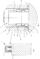
Figure 3 is a longitudinal section taken along the plane III-III inFigure 2 ; -
Figure 4 is an enlarged detail ofFigure 3 ; -
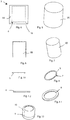
Figures 5 and 6 are two different views of an outer metal casing body of the cap according to the invention; -
Figures 7 and 8 are two different views of an inner metal cladding body of the cap according to the invention; -
Figures 9 and 10 are two different views of an elastic metal ring included in the cap according to the invention; -
Figures 10 and 11 are two different views of a metal annular element included in the cap according to the invention; -
Figure 13 shows a metal ferrule element suitable for being fixed to the perfume bottle. - With reference to the enclosed figures, a
closing system 1 for closing acontainer 2 is shown, in particular for aperfume bottle 2. - The
closing system 1 comprises acap 3, made completely of metal, suitable for closing amouth portion 4 of thebottle 2. To thusmouth portion 4, a pressure device can be fitted for dispensing a spray, i.e. a little pump that is drivable by the user to spray on herself or himself the perfume. As disclosed in detail below, thecap 3 is provided with engagingelastic means 5, which are also made of metal, which are suitable for snap engaging with anannular protrusion 9 provided on thebottle 2. - In particular, the
annular protrusion 9 can be obtained directly on the neck of theglass bottle 2, or, as in the example shown in the appended figures, can be part of aferrule element 10, and constrained on thebottle 2, defining at least in part themouth portion 4 thereof. - In
figure 4 an example of configuration of theferrule element 10 is shown better. In this example, theferrule element 10 abuts below on an upper boundingsurface 11 bounding thebottle 2, and has above acurved edge portion 12 inside anannular recess 13 with which it engages and remains firmly constrained. Theannular recess 13 is obtained on astatic component 14, fixed to thebottle 2, which is part of the little pump device that is not shown. - The
cap 3 comprises anouter casing body 3A made of metal and aninner cladding body 3B which is also made of metal and is fixed inside saidcasing body 3A. - The
outer casing body 3A, in particular, is made of a metal alloy with a high level of zinc of significant purity, combined with small percentages of aluminium, magnesium and copper. A metal alloy of this kind is commonly known by the commercial name "Zama". - Alternatively, the
outer casing body 3A can be made of brass or aluminium, or other metals or suitable metal alloys. - The use of the metal material to make the
outer casing body 3A gives theclosing system 1, in particular thecap 3, a valued and pleasing aesthetic appearance, very appreciated by a user who perceives the product as being provided with high quality. - The inner
cladding body 3B, of almost cylindrical shape, extends longitudinally inside the cavity of thecasing body 3A for a large part of the longitudinal dimension of the cavity itself. - The
inner cladding body 3B is made of aluminium or aluminium alloy, or another suitable metal material. - The
inner cladding body 3B can be coupled with theouter casing body 3A by joint, or by mechanical interference or by gluing. - The assembly defined by the
outer casing body 3A and by theinner cladding body 3B is thus completely made of metal. - Making not only the
casing body 3A but also theinner cladding body 3B of metal significantly increases the sensation of quality perceived by the user. - The
casing body 3A and theinner cladding body 3B define together ahousing seat 6 for the aforesaid engagingelastic means 5. - According to a different possible embodiment, the
cap 3 can consist of only thecasing body 3A. In other words, thecap 3 can be devoid of thecladding body 3B, and the inside of thecasing body 3A can be for example painted. - In this version, the
housing seat 6, obtained for example by removing in the thickness of thecasing body 3A, will be shaped with a suitable geometry that is suitable for housing the engagingelastic means 5. - The engaging elastic means, in particular, comprises a metal
elastic ring 5, configured to expand elastically radially when it interacts in contact with the aforesaidannular retaining protrusion 9 provided on themouth portion 4 of thebottle 2. - In particular, the metal
elastic ring 5, made of iron or another suitable metallic material, has a zone ofdiscontinuity 7 that enables the metalelastic ring 5 to expand elastically in a radial direction. - The engaging
elastic ring 5, in the rest condition, has a lesser inner diameter than the outer diameter of theannular protrusion 9. During the coupling step, the zone ofdiscontinuity 7 enables the engagingelastic ring 5 to expand temporarily to advance beyond theannular protrusion 9 and be positioned below the latter. Theannular protrusion 9 thus secures the engagingelastic ring 5 in the engagement position, and thus thecap 3 is firmly coupled with thebottle 2. Exerting appropriate tensile force on thecap 3 to remove it from thebottle 2 means that the engagingelastic ring 5 expands again to pass beyond theannular protrusion 9. At this point, thecap 3 is easily separable from themouth portion 4. - The
housing seat 6 is shaped as an annular groove obtained in thecasing body 3A and is bounded above partially by the innercladding body 3B. In other words, the innercladding body 3B, of cylindrical shape, extends, in thecasing body 3A for a lesser length than the longitudinal extent of the cavity of thecasing body 3A itself. In particular, the lower end of theinner cladding body 3B ends at the annular groove obtained in thecasing body 3A and concurs therewith to define thehousing seat 6 for theelastic ring 5. The outer diameter of theannular housing seat 6 is sized to enable the metalelastic ring 5 to expand radially during snap coupling of thecap 3 with thebottle 2. - The
cap 3 comprises an annular, also metal, retainingelement 8, fixed to a base portion of thecasing body 3A and which is shaped to retain in thehousing seat 6 the engagingelastic ring 5. - In particular, the
annular element 8 has a lesser inner diameter than the outer diameter of theelastic ring 5, and this ensures the correct operation of retaining the latter in theseat 6 thereof. - The
annular element 8 is housed in arespective seat 15 of circumferal shape, or another shape, which extends below theseat 6 of theelastic ring 5. - The
circumferal seat 15 has a maximum diameter that is greater than theseat 6. - To sum up, the
cap 3 consists of the following parts: - casing
body 3A, -
inner cladding body 3B, - engaging
elastic ring 5, -
annular retaining element 8, - The operation of the
closing system 1 is disclosed briefly below. - In order to close the
bottle 2, thecap 3 is put on themouth portion 4, and pressed thereupon. The engagingelastic ring 5, which in the rest condition has a lesser inner diameter than the outer diameter of theannular protrusion 9, is forced to expand to overcome, by sliding thereupon, theannular protrusion 9 itself. The passage from the position above theannular protrusion 9 to the position below it is rapid and of snap type and this hooking operation provides the user with pleasing tactile feedback, which assures the user that thebottle 2 has been closed correctly. - In order to open the
bottle 2, the user has to exert appropriate tensile force on thecap 3 that is sufficient to force the engagingelastic ring 5 to expand again to pass above theannular protrusion 9. At this point, thecap 3 is easily removable from themouth portion 4. - From what has been disclosed, claimed and shown in the appended figures, it is clear that the
closing system 1, in particular thecap 3 according to the invention, achieves successfully all the set objects, by overcoming all the limits inherent in the prior art systems. - In particular, an
improved closing system 1 is provided, thecap 3 of which is provided with a new spring mechanism for hooking with thebottle 2. The hooking mechanism with metalelastic element 5 ensures an effective mechanical coupling that is more reliable and precise over time. At the same time, this solution makes it possible to use only metal material to make theentire cap 3, thus fully meeting current market needs. - It is possible to configure and size the
closing system 1 in a desired manner in function of specific needs, with possible variations on and/or additions to what has been disclosed above and illustrated in the appended drawings. - The
ferrule element 10 can be made of aluminium by drawing or can be made of Zama and be constrained by interference or other coupling systems to thebottle 2. Theferrule element 10 can also be made of plastics by injection. - What has been said and shown in the appended drawings has been shown by way of illustration of the innovative features of the
closing system 1, so other modifications can be made to the frame, or to parts thereof, without thereby falling outside the claims. - In practice, the materials, insofar as they are compatible with the specific use and with the respective single elements for which they are intended, can be chosen opportunely in function of the required requirements and in function of the available prior art.
Claims (12)
- Closing system for a container (2), in particular for a perfume bottle (2), said closing system (1) comprising a cap (3) suitable for closing a mouth portion (4) of said perfume bottle (2), wherein said cap (3) is made completely of metal and comprises engaging elastic means (5) for snap coupling with said mouth portion (4), and wherein said cap (3) comprises an outer casing body (3A) made of metal and an inner cladding body (3B) made of metal, fixed inside said casing body (3A), wherein said casing body (3A) and said inner cladding body (3B) define together a housing seat (6) for said engaging elastic means (5).
- Closing system according to claim 1, wherein said engaging elastic means comprises a metal elastic ring (5), configured to expand elastically radially upon interaction with an annular retaining protrusion (9) of said mouth portion (4) and again contract to the rest position, said metal elastic ring (5) being shaped for engaging in a zone below said annular retaining protrusion (8).
- Closing system according to claim 1 or 2, wherein said housing seat (6) is obtained by removing material in the thickness of said cap (3).
- Closing system according to claim 2 or according to claim 3 as appended to claim 2, wherein said housing seat (6) is shaped as an annular groove obtained in said casing body (3A) and is bounded above partially by said inner cladding body (3B), said housing seat (6) being dimensioned to enable said metal elastic ring (5) to expand radially during snap coupling of said cap (3) with said mouth portion (4) of said bottle (2).
- Closing system according to claim 2 or according to claim 3 or 4 as appended to claim 2, wherein said metal elastic ring (5) is made of iron and has a zone of discontinuity (7) for radial elastic expansion/contraction.
- Closing system according to any one of the preceding claims, wherein said cap (3) comprises a metal annular element (8), fixed to a base portion of said casing body (3A) and shaped for retaining in said housing seat (6) said engaging elastic means (5).
- Closing system according to any one of the preceding claims, wherein said outer casing body (3A) is made of a metal alloy with a high level of zinc of significant purity, combined with small percentages of aluminium, magnesium and copper.
- Closing system according to any one of claims 1 to 6, wherein said outer casing body (3A) is made of brass or aluminium.
- Closing system according to any one of the preceding claims, in which said inner cladding body (3B) is made of aluminium or an aluminium alloy.
- Closing system according to claim 2, or according to one of claims 3 to 9, as appended to claim 2, comprising a substantially cylindrical ferrule element (10) shaped for being fixed to said bottle (2) to define said mouth portion (4), on said ferrule element (10) said annular protrusion (9) being obtained that is suitable for engaging with and retaining, said metal elastic ring (5).
- Closing system according to claim 10, in which said ferrule element (10) is made of metal.
- Perfume bottle comprising a closing system (1) according to any one of the preceding claims.
Applications Claiming Priority (1)
| Application Number | Priority Date | Filing Date | Title |
|---|---|---|---|
| IT102019000006723A IT201900006723A1 (en) | 2019-05-10 | 2019-05-10 | CLOSURE SYSTEM FOR A CONTAINER, IN PARTICULAR FOR A PERFUME BOTTLE |
Publications (1)
| Publication Number | Publication Date |
|---|---|
| EP3736227A1 true EP3736227A1 (en) | 2020-11-11 |
Family
ID=67660699
Family Applications (1)
| Application Number | Title | Priority Date | Filing Date |
|---|---|---|---|
| EP20173676.6A Withdrawn EP3736227A1 (en) | 2019-05-10 | 2020-05-08 | Closing system for a container |
Country Status (2)
| Country | Link |
|---|---|
| EP (1) | EP3736227A1 (en) |
| IT (1) | IT201900006723A1 (en) |
Cited By (2)
| Publication number | Priority date | Publication date | Assignee | Title |
|---|---|---|---|---|
| FR3117317A1 (en) * | 2020-12-15 | 2022-06-17 | Axilone Metal Sa | CLOSURE ELEMENT AND ASSEMBLY FOR CONTAINER FOR COSMETICS PRODUCT |
| FR3163810A1 (en) | 2024-06-27 | 2026-01-02 | L'oreal | Device for conditioning and applying a product |
Citations (4)
| Publication number | Priority date | Publication date | Assignee | Title |
|---|---|---|---|---|
| US2415609A (en) * | 1944-12-15 | 1947-02-11 | Bell Products Corp | Container |
| GB666293A (en) * | 1949-05-27 | 1952-02-06 | Paton Co Ltd Calvert | Improvements in or relating to canisters |
| GB2244479A (en) * | 1988-12-09 | 1991-12-04 | Glud & Marstrand As | A container with a lid |
| US20150246758A1 (en) * | 2012-10-05 | 2015-09-03 | Qualipac | Method for assembling a packaging device |
-
2019
- 2019-05-10 IT IT102019000006723A patent/IT201900006723A1/en unknown
-
2020
- 2020-05-08 EP EP20173676.6A patent/EP3736227A1/en not_active Withdrawn
Patent Citations (4)
| Publication number | Priority date | Publication date | Assignee | Title |
|---|---|---|---|---|
| US2415609A (en) * | 1944-12-15 | 1947-02-11 | Bell Products Corp | Container |
| GB666293A (en) * | 1949-05-27 | 1952-02-06 | Paton Co Ltd Calvert | Improvements in or relating to canisters |
| GB2244479A (en) * | 1988-12-09 | 1991-12-04 | Glud & Marstrand As | A container with a lid |
| US20150246758A1 (en) * | 2012-10-05 | 2015-09-03 | Qualipac | Method for assembling a packaging device |
Cited By (5)
| Publication number | Priority date | Publication date | Assignee | Title |
|---|---|---|---|---|
| FR3117317A1 (en) * | 2020-12-15 | 2022-06-17 | Axilone Metal Sa | CLOSURE ELEMENT AND ASSEMBLY FOR CONTAINER FOR COSMETICS PRODUCT |
| CN114631679A (en) * | 2020-12-15 | 2022-06-17 | 阿克西洛内金属公司 | Closure element and assembly for cosmetic containers |
| EP4014786A1 (en) * | 2020-12-15 | 2022-06-22 | Axilone Metal SA | Aluminium clip |
| US11834238B2 (en) | 2020-12-15 | 2023-12-05 | Axilone Metal Sa | Closing element and assembly for a cosmetic product container |
| FR3163810A1 (en) | 2024-06-27 | 2026-01-02 | L'oreal | Device for conditioning and applying a product |
Also Published As
| Publication number | Publication date |
|---|---|
| IT201900006723A1 (en) | 2020-11-10 |
Similar Documents
| Publication | Publication Date | Title |
|---|---|---|
| KR101996194B1 (en) | Screw-type container-closed system with magnetic features | |
| EP3736227A1 (en) | Closing system for a container | |
| CN110937246B (en) | Removable cap, dispensing bottle and method for producing a second decorative element of a removable cap of a dispensing bottle | |
| EP2975967B1 (en) | Compact using applicator as pushbutton | |
| KR102114082B1 (en) | Magnetic closure system for containers with wanded applicators and wipers | |
| US20050061814A1 (en) | Dispensing closure for a container that holds pourable material | |
| JP2002503602A (en) | Cap outside opening indication | |
| US20230107932A1 (en) | Casing for a refillable container device for cosmetic product and associated container device | |
| US20180290794A1 (en) | Axial magnetic attraction device | |
| US20170088315A1 (en) | Screw-type container-closure systems with magnetic feature | |
| JP6463836B2 (en) | Container cap assembly | |
| US5181790A (en) | Display and applicator container for waxy products | |
| MXPA06007622A (en) | Tool for applying liquid cosmetic material. | |
| EP3426411B1 (en) | Dispenser pumps | |
| KR101947715B1 (en) | Refill container having multiple sealing structure | |
| US8651759B2 (en) | Cylindrical cosmetic container | |
| US20200406280A1 (en) | Container for fluid product | |
| CN215555622U (en) | Multi-cavity integrated container | |
| KR20190001740A (en) | Cosmetic vessel with pump | |
| JP3325740B2 (en) | Mounting rivet cover | |
| EP2250923B1 (en) | Cylindrical cosmetic container | |
| US11731147B2 (en) | Assembly for dispensing a fluid product | |
| EP3889061A1 (en) | Vacuum, gas and liquid tight container with a reusable cap | |
| HK1256064B (en) | Screw-type closure systems with magnetic feature | |
| JPH11268758A (en) | Metering dispensing application container |
Legal Events
| Date | Code | Title | Description |
|---|---|---|---|
| PUAI | Public reference made under article 153(3) epc to a published international application that has entered the european phase |
Free format text: ORIGINAL CODE: 0009012 |
|
| STAA | Information on the status of an ep patent application or granted ep patent |
Free format text: STATUS: THE APPLICATION HAS BEEN PUBLISHED |
|
| AK | Designated contracting states |
Kind code of ref document: A1 Designated state(s): AL AT BE BG CH CY CZ DE DK EE ES FI FR GB GR HR HU IE IS IT LI LT LU LV MC MK MT NL NO PL PT RO RS SE SI SK SM TR |
|
| AX | Request for extension of the european patent |
Extension state: BA ME |
|
| STAA | Information on the status of an ep patent application or granted ep patent |
Free format text: STATUS: REQUEST FOR EXAMINATION WAS MADE |
|
| 17P | Request for examination filed |
Effective date: 20210510 |
|
| RBV | Designated contracting states (corrected) |
Designated state(s): AL AT BE BG CH CY CZ DE DK EE ES FI FR GB GR HR HU IE IS IT LI LT LU LV MC MK MT NL NO PL PT RO RS SE SI SK SM TR |
|
| STAA | Information on the status of an ep patent application or granted ep patent |
Free format text: STATUS: EXAMINATION IS IN PROGRESS |
|
| 17Q | First examination report despatched |
Effective date: 20211124 |
|
| GRAP | Despatch of communication of intention to grant a patent |
Free format text: ORIGINAL CODE: EPIDOSNIGR1 |
|
| STAA | Information on the status of an ep patent application or granted ep patent |
Free format text: STATUS: GRANT OF PATENT IS INTENDED |
|
| INTG | Intention to grant announced |
Effective date: 20230721 |
|
| STAA | Information on the status of an ep patent application or granted ep patent |
Free format text: STATUS: THE APPLICATION IS DEEMED TO BE WITHDRAWN |
|
| 18D | Application deemed to be withdrawn |
Effective date: 20231201 |