EP3738629A1 - Medizinische spritze mit nadelschutz - Google Patents
Medizinische spritze mit nadelschutz Download PDFInfo
- Publication number
- EP3738629A1 EP3738629A1 EP19174929.0A EP19174929A EP3738629A1 EP 3738629 A1 EP3738629 A1 EP 3738629A1 EP 19174929 A EP19174929 A EP 19174929A EP 3738629 A1 EP3738629 A1 EP 3738629A1
- Authority
- EP
- European Patent Office
- Prior art keywords
- needle
- syringe
- piston
- hollow body
- plunger
- Prior art date
- Legal status (The legal status is an assumption and is not a legal conclusion. Google has not performed a legal analysis and makes no representation as to the accuracy of the status listed.)
- Granted
Links
Images





Classifications
-
- A—HUMAN NECESSITIES
- A61—MEDICAL OR VETERINARY SCIENCE; HYGIENE
- A61M—DEVICES FOR INTRODUCING MEDIA INTO, OR ONTO, THE BODY; DEVICES FOR TRANSDUCING BODY MEDIA OR FOR TAKING MEDIA FROM THE BODY; DEVICES FOR PRODUCING OR ENDING SLEEP OR STUPOR
- A61M5/00—Devices for bringing media into the body in a subcutaneous, intra-vascular or intramuscular way; Accessories therefor, e.g. filling or cleaning devices, arm rests
- A61M5/178—Syringes
- A61M5/31—Details
- A61M5/32—Needles; Details of needles pertaining to their connection with syringe or hub; Accessories for bringing the needle into, or holding the needle on, the body; Devices for protection of needles
- A61M5/3205—Apparatus for removing or disposing of used needles or syringes, e.g. containers; Means for protection against accidental injuries from used needles
- A61M5/321—Means for protection against accidental injuries by used needles
- A61M5/322—Retractable needles, i.e. disconnected from and withdrawn into the syringe barrel by the piston
-
- A—HUMAN NECESSITIES
- A61—MEDICAL OR VETERINARY SCIENCE; HYGIENE
- A61M—DEVICES FOR INTRODUCING MEDIA INTO, OR ONTO, THE BODY; DEVICES FOR TRANSDUCING BODY MEDIA OR FOR TAKING MEDIA FROM THE BODY; DEVICES FOR PRODUCING OR ENDING SLEEP OR STUPOR
- A61M5/00—Devices for bringing media into the body in a subcutaneous, intra-vascular or intramuscular way; Accessories therefor, e.g. filling or cleaning devices, arm rests
- A61M5/178—Syringes
- A61M5/31—Details
- A61M5/315—Pistons; Piston-rods; Guiding, blocking or restricting the movement of the rod or piston; Appliances on the rod for facilitating dosing ; Dosing mechanisms
- A61M5/31511—Piston or piston-rod constructions, e.g. connection of piston with piston-rod
- A61M2005/31516—Piston or piston-rod constructions, e.g. connection of piston with piston-rod reducing dead-space in the syringe barrel after delivery
-
- A—HUMAN NECESSITIES
- A61—MEDICAL OR VETERINARY SCIENCE; HYGIENE
- A61M—DEVICES FOR INTRODUCING MEDIA INTO, OR ONTO, THE BODY; DEVICES FOR TRANSDUCING BODY MEDIA OR FOR TAKING MEDIA FROM THE BODY; DEVICES FOR PRODUCING OR ENDING SLEEP OR STUPOR
- A61M5/00—Devices for bringing media into the body in a subcutaneous, intra-vascular or intramuscular way; Accessories therefor, e.g. filling or cleaning devices, arm rests
- A61M5/178—Syringes
- A61M5/31—Details
- A61M5/32—Needles; Details of needles pertaining to their connection with syringe or hub; Accessories for bringing the needle into, or holding the needle on, the body; Devices for protection of needles
- A61M5/3205—Apparatus for removing or disposing of used needles or syringes, e.g. containers; Means for protection against accidental injuries from used needles
- A61M5/321—Means for protection against accidental injuries by used needles
- A61M5/322—Retractable needles, i.e. disconnected from and withdrawn into the syringe barrel by the piston
- A61M5/3221—Constructional features thereof, e.g. to improve manipulation or functioning
- A61M2005/3223—Means impeding or disabling repositioning of used needles at the syringe nozzle
-
- A—HUMAN NECESSITIES
- A61—MEDICAL OR VETERINARY SCIENCE; HYGIENE
- A61M—DEVICES FOR INTRODUCING MEDIA INTO, OR ONTO, THE BODY; DEVICES FOR TRANSDUCING BODY MEDIA OR FOR TAKING MEDIA FROM THE BODY; DEVICES FOR PRODUCING OR ENDING SLEEP OR STUPOR
- A61M5/00—Devices for bringing media into the body in a subcutaneous, intra-vascular or intramuscular way; Accessories therefor, e.g. filling or cleaning devices, arm rests
- A61M5/178—Syringes
- A61M5/31—Details
- A61M5/32—Needles; Details of needles pertaining to their connection with syringe or hub; Accessories for bringing the needle into, or holding the needle on, the body; Devices for protection of needles
- A61M5/3205—Apparatus for removing or disposing of used needles or syringes, e.g. containers; Means for protection against accidental injuries from used needles
- A61M5/321—Means for protection against accidental injuries by used needles
- A61M5/322—Retractable needles, i.e. disconnected from and withdrawn into the syringe barrel by the piston
- A61M5/3221—Constructional features thereof, e.g. to improve manipulation or functioning
- A61M2005/3231—Proximal end of needle captured or embedded inside piston head, e.g. by friction or hooks
Definitions
- the invention relates to a medical syringe with a needle guard with a piston which can be displaced in the interior of a syringe body via an actuating plunger.
- syringes with so-called pull-in or retraction systems for the syringe needle are increasingly used.
- the syringe needle is drawn into the syringe body after the active substance contained in the syringe has been dispensed and completely enclosed by it. Access to the syringe and thus the risk of injury, or the risk of using the same needle multiple times, can thus be largely ruled out.
- Such syringes with passive needle protection are for example from the EP 1 284 769 B1 , the EP 0 720 491 B1 , the EP 0 680 347 B1 or the EP 1 764 127 B1 known.
- the piston which is displaceable in the interior of the syringe body has a needle holder provided for receiving the syringe needle, the needle bearing of which is arranged on a retaining bracket leaving a number of lateral inflow surfaces free.
- the invention is based on the consideration that the complete discharge of the active ingredient as a result of the displacement of the plunger inside the syringe housing towards its distal end is essentially limited by the so-called dead volume, i.e. pockets or dead spaces within the housing that are due to the geometry the active substance can no longer flow out via the needle when the piston is completely displaced.
- dead volumes i.e. pockets or dead spaces within the housing that are due to the geometry the active substance can no longer flow out via the needle when the piston is completely displaced.
- these dead spaces should therefore be kept particularly small, and specific outflow channels should be provided through which the active substance can still flow to the inlet end of the needle even when the plunger is far advanced.
- the system for capturing and entraining the needle should therefore enable the active substance to flow as far as possible to the inner end of the needle, even when the piston is pushed far forward. This is achieved in that the needle is gripped by a bracket which, in its lateral areas, leaves free inflow surfaces for the active substance, via which the active substance can then still flow toward the needle.
- the needle holder is advantageously made as a plastic part, preferably made of polypropylene.
- the base material is called "Bormed TM" with regard to the expected required holding forces and the mechanical loads expected when used as intended, but also with regard to approval-related requirements (HD810MO, ISO 10993 Information (Biocompatibility)) available polypropylene.
- the needle holder is advantageously surrounded by a piston jacket which is shaped in such a way that, when the needle holder is inserted, it leaves a number of inflow channels free for the active substance to the side of the retaining bracket.
- the piston skirt is preferably made of rubber.
- the medical syringe 1 with needle retraction according to FIG Fig. 1 essentially comprises two assemblies, namely a cartridge unit 2 on the one hand and an actuating plunger 4 on the other hand.
- the medical syringe 1 has a two-component structure, the two assemblies mentioned forming separate components that can be connected to one another in the manner described below.
- the syringe could also be one-component be executed, the two assemblies mentioned are connected to each other from the outset and the distinction between the two assemblies is only functional.
- the cartridge or cartridge unit 2 forms the actual syringe and comprises a hollow body 6 which is cylindrical or tubular in accordance with a conventional design and forms a syringe housing and is provided for receiving the medicinal substance.
- a needle holder 10 is attached to the front or distal end 8 of the hollow body 6, in which the hollow needle 12 provided for the injection of the active substance is mounted in a bearing sleeve 14.
- the needle holder 10 could be designed in one piece with the hollow body 6 forming the syringe housing. In the exemplary embodiment, however, the needle holder 10 is designed as a separate component in an embodiment that is regarded as independently inventive.
- the needle holder 10 is slipped or attachable onto the hollow body 6 or the syringe cone forming the syringe housing, but could also be designed to be screwed on by means of a thread, for example a Luer thread.
- the needle 12 is surrounded by a removable protective cap (not shown in detail), which is removed before the syringe 1 is used.
- the rear or proximal end 16 of the hollow body 6 forming the syringe housing can be closed by a plunger 18 which is slidable within the hollow body 6 and is adapted to fit the inner contour of the hollow body 6 with an exact fit.
- a plunger 18 which is slidable within the hollow body 6 and is adapted to fit the inner contour of the hollow body 6 with an exact fit.
- the piston 18 On its end face facing the interior of the hollow body 6, the piston 18 has a center hole 20 for the needle 12.
- the drive or actuation plunger 4 comprises a pusher plate 22 provided on the one hand at the end and the pusher plate 22 on the other opposite end 24 with a coupling element 26 provided for connection to the piston 18. With its shaft 28 extending between the pusher plate 20 and coupling element 26, the actuating plunger 4 is guided through a cover plate 30 in the assembled state of the components and in it in its Slidable lengthways.
- the piston 18 could be designed in one piece with the actuating tappet 4. In the exemplary embodiment, however, these components are designed separately. As shown in Fig. 2 can be removed, the piston 18 has, for connection to the shaft 28 of the actuating tappet 4, a fastening pin 36 formed on the end and provided with a circumferential groove. Corresponding to this and adapted to this in terms of its dimensions, the coupling element 26 formed on the end of the shaft 28 is provided with an elongated hole 38 open on one side. The fastening pin 36 can be pushed laterally into this, so that the side edge of the elongated hole 38 engages in the circumferential groove of the fastening pin 36 and a form fit is thus created between these components when viewed in the longitudinal direction.
- the medical syringe 1 is provided with a needle guard designed in the manner of a retraction system by the components and parts mentioned.
- the purpose of this is that after the syringe 1 has been used, i.e. after the active substance stored in the hollow body 6 forming the syringe housing has been dispensed via the needle 12, it is drawn into the syringe housing in such a way that it is completely enclosed by the syringe housing. In this way, inadvertent contact with the used needle 12, for example by auxiliary or nursing staff, and thus the risk of injury and contamination, is to be kept particularly low or completely excluded.
- the syringe 1 could in principle be used with the cartridge or cartridge unit 2 pre-filled.
- the cartridge filled with the active substance would or a cartridge unit 2 with a piston 18 already introduced into the hollow body 6 and closing its interior.
- the first step in use is then according to the in Fig. 2 illustrated manner the actuating plunger 4 is connected at the end to the piston 18, and the system is ready to dispense the active ingredient.
- the syringe 1 is made ready for use when it is empty and is filled with the active substance by drawing it up.
- Fig. 4 can be removed, the actuating tappet 4 carrying the piston 18 is pushed into the receiving hole 40 provided for this in the cover plate 30, so that the piston 18 is introduced into the interior of the hollow body 6.
- the receiving hole 40 with its outer edge 42 designed in the manner of a guide slot and correspondingly the cross section of the shaft 28 of the actuating plunger 4 are designed in such a way that the actuating plunger 4 is introduced in a predetermined rotational orientation relative to the hollow body 6 or its cover plate 30 .
- the actuating plunger 4 is then pressed by the operator while maintaining this rotational orientation - this is achieved by a cross-sectional geometry of the shaft 28 that is constant in the longitudinal direction - so that the piston 18 moves within the hollow body 6 towards its distal end 8.
- a stop formed by the shaft 28 is formed in the manner of a step or edge, seen in the longitudinal direction abrupt cross-sectional change or widening of the shaft 28, so that the shaft 28 cannot be guided further through the outer edge 42 of the receiving hole 40 in the longitudinal direction.
- the cross-section of the shaft 28 and, correspondingly, the contour of the outer edge 42 of the receiving hole 40, which forms the guide slot, are designed in such a way that, when the said end position of the piston 18 within the hollow body 6 is reached, the rotational lock between the actuating plunger 4 and cover plate 30 is at least to a certain extent is canceled and the plunger 4 is rotatable in the cover plate 30 about its longitudinal axis by a predetermined angle of rotation, preferably approximately 90 °.
- a predetermined angle of rotation preferably approximately 90 °.
- this rotation also - again achieved through a suitable design of the cross section of the shaft 28 and adapted to the contour of the outer edge 42 - forms a new stop "upwards" or towards the proximal end 16 of the hollow body 6, so that over a predetermined end point of the actuating plunger 4 and in particular the piston 18 attached to this end can not be pulled out of the hollow body 6.
- the needle 12 for administering the medicinal substance is suitably positioned on the patient, so that it pierces the patient's skin at a suitable point.
- the holding force of the needle 12 in the bearing sleeve 14 is predetermined, in particular through suitable dimensioning of the components and / or the choice of material pairing, so that the needle 12 remains securely in its position in the bearing sleeve 14 when the operator manipulates the hollow body 6 pierces the needle 12 through the patient's skin.
- the actuating plunger 4 is then pressed by the operator, so that the piston 18 moves within the hollow body 6 towards its distal end 8 and in the process feeds the medical active substance to the needle 12 and discharges it via the latter.
- the piston 18 near the distal end 8 of the hollow body 6 reaches the end of the needle 12 that protrudes into the interior, so that, upon further movement, it enters the provided receiving hole 20 penetrates.
- the piston 18 then reaches its end position directly at the distal end 8 of the hollow body 6 and thereby encloses the part of the hollow needle 12 that protrudes into the receiving hole 20.
- the connection of the needle 12 to the piston 18 is also referred to here as "connecting".
- the operator pulls back the pusher plate 22 and with it the actuating plunger 4 as a whole.
- the piston 18, which is connected to the shaft 28 of the actuating plunger 4 via the coupling element 26, is carried along and pulled within the hollow body 6 away from the distal end 8 towards the proximal end 16. In doing so, he in turn takes the enclosed needle 12 with him and pulls it into the hollow body 6 so that it is positioned completely within the hollow body 6 in the final state.
- FIG. 5 shows Figure 5a the syringe 1 before the administration of the active substance held in the interior of the hollow body 6.
- the piston 18 guided in the interior of the hollow body 6 is located at its stop on the cover plate 30 arranged at the proximal end 16 of the hollow body 6.
- the actuating plunger 4 is accordingly fully extended and the pusher plate 22 is at the maximum distance D from the cover plate 30
- the hollow needle 12 held in the needle holder 10 is extended ready for use in this state.
- the hollow needle 12 is independently inventive according to the following description.
- the hollow needle 12 comprises in an independent inventive embodiment a needle tube 50 made of metal, which forms a needle tip 52, 54 at each of its two ends.
- the choice of material for the needle tube 50 is preferably made in a manner suitable for common requirements for medical applications, with a stainless material that can also be used for standard needles being particularly preferably provided.
- the needle tube 50 is designed to be sheathed and surrounded by a plastic sheath 56.
- the material for the plastic jacket 56 is preferably a polyamide (PA12), very particularly preferably that available commercially under the name Vestamid Care ML 17.
- the plastic jacket 56 is sprayed onto the needle tube 50, which is also considered to be inventive in its own right, after it has been subjected to a plasma pretreatment in the manner of surface activation. A particularly good adhesion of the plastic forming the plastic jacket 56 to the needle 50 can thus be achieved.
- Two retaining grooves 58, 60 are formed in the plastic jacket 56, which are intended to enable the mode of operation described above.
- the first retaining groove 58 is provided for the temporary fixation of the needle 12 in the bearing sleeve 14 of the needle holder 10.
- an associated circumferential locking lip is provided within the bearing sleeve 14, which, when the needle 12 is installed and properly inserted into the bearing sleeve 14, engages in the holding groove 58 and fixes it in the longitudinal direction.
- the dimensions of the retaining groove 58 and the locking groove are advantageously selected in such a way that, taking into account the deformability of the material of the plastic jacket 56 and / or a possible adhesive force due to the material pairing of the material of the plastic jacket 56 and that surrounding it Material of the bearing sleeve 14, the holding or breakaway force of the needle 12 locked in this way is sufficiently large in the longitudinal direction on the one hand so that the needle 12 can be pierced into the patient's skin according to the procedure described above, but on the other hand is also sufficiently small so that the described retraction movement of the needle 12 towards the interior of the hollow body 6 can be carried out.
- the profile of the retaining groove 58 can also be designed correspondingly asymmetrically, with a comparatively steep flank angle at its tip 54 facing the interior Side and a comparatively flat flank angle on its side facing the exposed tip 52.
- the second retaining groove 60 is provided for a corresponding latching in the piston 18.
- the needle 12 is shown in the state inserted into the piston 18.
- the piston 18 is in turn made in several parts and includes the in the Figs. 6, 7
- the needle holder 62 according to the invention is also shown.
- the needle holder 62 is designed as a plastic part and consists in the exemplary embodiment with regard to the required holding forces and the mechanical loads expected when used as intended, but also with regard to approval-related requirements from the under the name "Bormed TM" ( HD810MO, ISO 10993 Information (Biocompatibility)) available polypropylene.
- the needle holder 62 comprises a retaining bracket 66 which is molded onto a base body 64 and which carries the actual needle bearing 68 which forms the receiving hole 20.
- the needle bearing 68 is, analogously to the bearing sleeve 14 described above, provided on the inside with an associated circumferential locking lip which, when the needle 12 is pushed into the needle bearing 68, engages in the second retaining groove 60 and fixes it in the longitudinal direction.
- the dimensions of the retaining groove 60 and the locking groove assigned to it in the needle bearing 68 are advantageously selected such that, taking into account the deformability of the material of the plastic jacket 56 and / or any adhesive force due to the material pairing of the material of the Plastic jacket 56 and the surrounding material of the needle bearing 68, the holding or breakaway force of the needle 12 locked in this way is greater in the longitudinal direction than the corresponding holding or breakaway force of the holding groove 58 in the bearing sleeve 14, so that when the piston 18 retracts the needle 12 is taken from this to the interior of the hollow body 6.
- the design of the retaining bracket 66 also creates a free space within the piston 18 which, in the final phase of the application of the active ingredient, in which the needle tip 54 has already penetrated into the receiving hole 20 and is therefore no longer readily accessible for the active ingredient, in the A type of bypass enables the active substance to flow into the needle tube 50 via the needle tip 54.
- the inflow can take place on both sides of the retaining bracket 66 into the free space.
- the piston 18 is constructed in several parts.
- a piston jacket 70 surrounding the needle 12 is provided.
- the piston skirt 70 consists of conventional rubber, particularly preferably of the material available from the Kreiburg company under the name TM4RST (MC / RS Series), taking into account the approval-related requirements.
- the piston skirt 70 is shaped in such a way that when the needle holder 62 is inserted, it leaves inflow channels free for the active substance on both sides of the retaining bracket 66, so that the bypass for the desired zero volume ejection is formed in order to avoid or minimize the dead volume.
- the shaft 28 of the actuating plunger is required 4 provided.
- the shaft 28 is essentially formed by two crossed shaft ribs 72, 74 that form a cross in cross section.
- the shaft rib 74 has a protrusion so that An edge 76 is formed here.
- the edge 76 strikes the cover plate 30 and thus limits this inward movement.
- the first shaft rib having the edge 76 is rotated to overlap with a guide groove 78 formed by the outer contour 42 of the receiving hole 40, so that in this orientation the actuating plunger 4 can be moved even further towards the distal end 8 of the hollow body 6.
- a notch 80 is provided in the shaft ribs 72, 74, into which a securing spring 82 arranged in the cover plate 30 can engage when appropriately positioned. This is used to fix the assumed position after retraction of the needle 12 into the interior of the hollow body 6 so that the needle 12 remains secured there.
- FIGS Figs. 10 ff. An alternative medical syringe 1 'with needle retraction, which is regarded as independently inventive, is shown in FIGS Figs. 10 ff. shown.
- This medical syringe 1 ' is provided in particular for cartridges pre-filled with active substance and essentially comprises three assemblies, namely a cartridge unit 102, a frame 106 provided with an actuating plunger 104 and a needle head 108 Fig. 11
- the enlarged cartridge or cartridge unit 102 is pre-filled with the active substance and comprises the actual cartridge body 110 designed as a cylindrical hollow body, which is closed at its proximal end 16 with the piston 18 ′. At the distal end 8, on the other hand, it is closed by a clipped or plugged-on cap 112, as shown in FIG Fig. 12 is shown.
- the cap 112 according to FIG. Fig. 12 comprises a cover 116 provided with a circumferential side skirt 114 provided as a clip for connection to the edge of the cartridge body 110.
- This comprises a central receiving hole 118 for the hollow needle 12, and it is provided on the inside with a preferably sprayed-on seal 120 made of a suitably selected material, in particular TPE.
- the side skirt 114 is surrounded by a slidable cover jacket 122. After clipping or bursting onto the edge of the cartridge body 110, the cover jacket 122 can be pushed over the side skirt 114 provided with latching hooks so that the hooking is fixed and the connection is secured.
- the in Fig. 13 The needle head 108 shown in an exploded view comprises the needle holder 10, the hollow needle 12 and a needle protection cap 124. In addition, a seal 126 is provided to maintain sterility.
- the syringe frame 106 comprises, as shown Fig. 14 It can be seen, a chamber body 130, which is open at the end and is preferably cylindrical or semi-cylindrical and is provided for receiving the cartridge unit 102, at the proximal end 132 of which, in addition to a finger rest 134, the actuating plunger 104, which in this exemplary embodiment is provided with a finger tab 136 at the end, is arranged.
- the chamber body 130 is surrounded by a needle protection sleeve 138 that is displaceable in the longitudinal direction.
- the piston 18 ′ is designed for a particularly simple coupling to the actuating tappet 104 in a manner which is regarded as being independently inventive.
- the actuating plunger 104 has a thickening 140 with a circumferential locking groove 142 at the end.
- the piston 18 ′ in this exemplary embodiment is provided with a receiving channel 144 into which the thickening 140 can be pushed.
- the receiving channel 144 is provided with a circumferential locking lip 146, which engages with the locking groove 142 when it is fully inserted.
- the piston 18 ' is thus connected to the actuating tappet 4'.
- Fig. 17 it is shown how the medical syringe 1 'is then made ready for use.
- the needle head 108 is attached. This can be done in a particularly simple manner by screwing on;
- the needle holder 10 in this exemplary embodiment is preferably provided on the outside with a preferably two-start Luer thread which interacts with a corresponding internal thread in the end region of the chamber body 130.
- the inside needle tip 54 in the receiving hole 118 pierces the seal 120 and thus projects into the interior of the cartridge body 110.
- the active ingredient can then be administered by pressing the actuating plunger 104, analogous to the mode of operation already described above, after the active ingredient has been completely dispensed, "connecting" the needle 12 to the plunger 18 'and introducing the corresponding portion of the hollow needle 12 into the receiving hole 20 of the Piston 18 'takes place. Then, here too, the operator pulls the actuating tappet 104 back again. In this way, the piston 18 ′ connected to the actuating tappet 104 and with it the enclosed needle 12 are also taken along here, so that the latter is completely drawn into the cartridge body 110. As the representation of this state in Fig. 18 is removable, the needle holder 10 can then be unscrewed again. Then, by pulling on the actuating plunger 104, the user can release its locking with the piston 18 ′ again, so that the cartridge body 110, which now completely encloses the needle 12, can be removed from the chamber body 130.
- the cartridge body 110 which is thus ready for safe disposal and completely enclosing the needle 12, is shown in FIG Fig. 19 shown.
- the frame 106 designed as a reusable system and provided for multiple use can be used for further use.
- FIG. 20 shows the medical syringe 1 ′′ before the active substance is dispensed.
- the medical syringe 1 ′′ is equipped with a double chamber or double piston system.
- the medical syringe 1 ′′ has a further, upstream piston 150 in addition to the piston 18 inside the hollow body 6. The space between the piston 18 and the further piston 150 creates a first active substance chamber 154 is formed, and the second active substance chamber 156 is then located between the further piston 150 and the apical end 8 of the hollow body 6.
- Such a double-chamber system is used in particular for liquid and / or lyophilized (freeze-dried) or powdered medicaments which have to be dissolved before administration.
- Such double-chamber systems are therefore a particularly suitable solution for lyophilized / liquid or liquid / liquid combinations of active ingredients.
- the system offers a number of advantages for sensitive injection drugs.
- the solvent is kept in stock, whereas the actual, e.g. B. freeze-dried or powdered active ingredient is located in the second active ingredient chamber 156.
- the solvent provided in the first active substance chamber 154 is initially removed from a molding via a molding arranged in the housing wall of the hollow body 6 158 bypass channel 160 formed in the housing jacket is introduced past the further piston 150 into the second active ingredient chamber 156. There it dissolves the active ingredient held there so that it is ready for administration.
- the piston 18 is moved as far as the stop on the piston 150, and then the pistons 18, 150 are moved further together so that the now dissolved active ingredient in the second active ingredient chamber 156 is discharged via the needle 12 .
- the needle holder 10 could also be designed in one piece with the hollow body 6 forming the syringe housing.
- the needle holder 10 is designed as a separate component and on the hollow body forming the syringe housing 6 or the syringe cone can be plugged on or plugged in.
- the needle holder 10 could also be constructed so that it can be screwed onto the hollow body 6 by means of a thread, in the present case in particular a Luer thread.
Landscapes
- Health & Medical Sciences (AREA)
- Engineering & Computer Science (AREA)
- Heart & Thoracic Surgery (AREA)
- Vascular Medicine (AREA)
- Anesthesiology (AREA)
- Biomedical Technology (AREA)
- Environmental & Geological Engineering (AREA)
- Hematology (AREA)
- Life Sciences & Earth Sciences (AREA)
- Animal Behavior & Ethology (AREA)
- General Health & Medical Sciences (AREA)
- Public Health (AREA)
- Veterinary Medicine (AREA)
- Infusion, Injection, And Reservoir Apparatuses (AREA)
Abstract
Description
- Die Erfindung betrifft eine medizinische Spritze mit Nadelschutz mit einem über einen Betätigungsstößel im Innenraum eines Spritzenkörpers verschiebbaren Kolben.
- Zur Vermeidung oder Verringerung von Kontaminations- oder Verletzungsrisiken nach dem Gebrauch von Medikamentenspritzen und insbesondere zur Vermeidung des mehrfachen Gebrauchs von Spritzennadeln durch verschiedene Nutzer finden Spritzen mit so genannten Einzieh- oder Retraktionssystemen für die Spritzennadel zunehmend Verwendung. Bei solchen insbesondere medizinischen Spritzen, auch als "Spritze mit (passivem) Nadelschutz" bezeichnet, wird die Spritzennadel nach Abgabe des in der Spritze vorgehaltenen Wirkstoffs in den Spritzenkörper eingezogen und von diesem vollständig umschlossen. Ein Zugang zur Spritze und damit ein Verletzungsrisiko, oder auch das Risiko mehrfachen Gebrauchs derselben Nadel, kann damit weitgehend ausgeschlossen werden.
- Derartige Spritzen mit passivem Nadelschutz sind beispielsweise aus der
EP 1 284 769 B1 , derEP 0 720 491 B1 , derEP 0 680 347 B1 oder derEP 1 764 127 B1 bekannt. - Ganz allgemein bei medizinischen Spritzen, und somit auch bei Spritzen mit Nadelschutz der genannten Art, besteht das Bedürfnis, beim Gebrauch der Spritze den darin enthaltenen Wirkstoff möglichst vollständig abzugeben und den Verbleib nicht genutzter Restmengen des Wirkstoffs innerhalb der Spritze möglichst weitgehend zu minimieren. Der Erfindung liegt nunmehr die Aufgabe zugrunde, eine Spritze mit Nadelschutz der oben genannten Art anzugeben, mit der diesem Bedürfnis Rechnung getragen ist.
- Diese Aufgabe wird erfindungsgemäß gelöst, indem der im Innenraum des Spritzenkörpers verschiebbare Kolben einen zur Aufnahme der Spritzennadel vorgesehenen Nadelhalter aufweist, dessen Nadellager unter Freilassung einer Anzahl seitlicher Einströmflächen an einem Haltebügel angeordnet ist.
- Vorteilhafte Ausgestaltungen der Erfindung sind Gegenstand der Unteransprüche und/oder der nachfolgenden Figurenbeschreibung entnehmbar.
- Die Erfindung geht von der Überlegung aus, dass die vollständige Ausbringung des Wirkstoffs infolge der Verschiebung des Kolbens innerhalb des Sprizengehäuses zu dessen distalem Ende hin im Wesentlichen durch das so genannte Totvolumen begrenzt wird, also geometriebedingt vorliegende Taschen oder Toträume innerhalb des Gehäuses, von denen aus der Wirkstoff bei vollständig verschobenem Kolben nicht mehr über die Nadel ausströmen kann. Für die angestrebte Minimierung der nach der Nutzung der Spritze in deren Gehäuse verbleibenden Wirkstoffreste sollten diese Toträume somit besonders klein gehalten werden, und es sollten gezielt Abströmkanäle bereitgestellt werden, über die der Wirkstoff auch bei weit vorgeschobenem Kolben noch dem Eintrittsende der Nadel zuströmen kann. Dies kann gerade bei Spritzen mit Nadelschutz problematisch sein, da bei derartigen Systemen die Nadel bei weit vorgeschobenem Kolben erfasst und anschließend mit dem Kolben in den Innenraum des Spritzengehäuses zurückgezogen werden muss. Das System zur Erfassung und Mitnahme der Nadel sollte daher auch bei weit vorgeschobenem Kolben eine möglichst weitgehende Zuströmung des Wirkstoffs zum inneren Nadelende ermöglichen. Dies wird erreicht, indem die Nadel über einen Bügel erfasst wird, der in seinen seitlichen Bereichen Zuströmflächen für den Wirkstoff freilässt, über den dieser der Nadel auch dann noch zuströmen kann.
- Vorteilhafterweise ist der Nadelhalter dabei als Kunststoffteil, vorzugsweise aus Polypropylen, gefertigt. Ganz besonders bevorzugt ist dabei als Basismaterial im Hinblick auf die erwarteten erforderlichen Haltekräfte und die bei bestimmungsgemäßem Gebrauch erwarteten mechanischen Belastungen, aber auch im Hinblick auf zulassungsbedingte Erfordernisse das unter der Bezeichnung "Bormed™" (HD810MO, ISO 10993 Information (Biocompatibility)) erhältliche Polypropylen vorgesehen.
- Vorteilhafterweise ist der Nadelhalter von einem Kolbenmantel umgeben, der derart geformt ist, dass er bei eingebrachtem Nadelhalter seitlich des Haltebügels eine Anzahl von Zuströmkanälen für den Wirkstoff freilässt. Der Kolbenmantel besteht dabei bevorzugt aus Gummi.
- Ein Ausführungsbeispiel der Erfindung wird anhand einer Zeichnung näher erläutert. Darin zeigen:
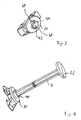
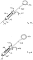
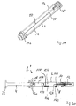
- Fig. 1
- eine medizinische Spritze mit Nadelschutz,
- Fig. 2
- eine Betätigungseinheit der Spritze nach
Fig. 1 in seitlicher Ansicht, - Fig. 3
- eine Deckelplatte der Spritze nach
Fig. 1 , - Fig. 4
- die Deckelplatte nach
Fig. 3 mit angesetztem Betätigungsstößel, - Fig. 5
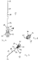
- eine Sequenz von Teilschnitten der Spritze gemäß
Fig. 1 , - Fig. 6
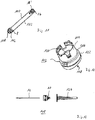
- eine zur Verwendung in der Spritze gem.
Fig. 1 vorgesehene, in einen Nadelhalter eingesteckte Nadel in seitlicher Ansicht, - Fig. 7
- die Nadel gem.
Fig. 6 in perspektivischer Ansicht, - Fig. 8
- einen Kolben der Spritze gem.
Fig. 1 , - Fig. 9
- einen Betätigungsstößel der Spritze gem.
Fig. 1 , - Fig. 10
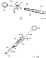
- eine alternative Ausführungsform einer medizinischen Spritze mit Nadelschutz,
- Fig. 11
- eine Kartuschen- oder Patroneneinheit der Spritze gem.
Fig. 10 , - Fig. 12
- eine Verschlusskappe der Kartuscheneinheit gem.
Fig. 11 , - Fig. 13
- den Nadelkopf der Spritze gem.
Fig. 10 in Explosionsdarstellung, - Fig. 14
- einen Spritzenrahmen der Spritze gem.
Fig. 10 , - Fig. 15
- die Kartuscheneinheit gem.
Fig. 11 unmittelbar vor (Fig. 15a ) und nach (Fig. 15b ) der Einbringung in den Spritzenrahmen gem.Fig. 14 , - Fig. 16
- den Verbindungsbereich zwischen Kolben und Betätigungsstößel der Spritze gem.
fig. 10 im Längsschnitt, - Fig. 17
- die Spritze gem.
Fig. 10 bei Anbringung und Freilegen der Nadel, - Fig. 18
- die Spritze gem.
Fig. 10 nach Ausbringung des Wirkstoffs und Retraktion der Nadel, - Fig. 19
- den Kartuschenkörper der Spritze gem.
Fig. 10 mit darin befindlicher eingezogener Nadel, und - Fig. 20
- eine weitere alternative Ausführungsform einer medizinischen Spritze mit Nadelschutz und Doppelkammersystem im Längsschnitt.
- Gleiche Teile sind in allen Figuren mit denselben Bezugszeichen versehen.
- Die medizinische Spritze 1 mit Nadelretraktion gemäß
Fig. 1 umfasst im Wesentlichen zwei Baugruppen, nämlich einerseits eine Kartuschen- oder Patroneneinheit 2 und andererseits einen Betätigungsstößel 4. Im Ausführungsbeispiel ist die medizinische Spritze 1 dabei zweikomponentig aufgebaut, wobei die beiden genannten Baugruppen separate, auf die nachstehend beschriebene Weise miteinander verbindbare Komponenten bilden. Alternativ könnte die Spritze aber auch einkomponentig ausgeführt sein, wobei die beiden genannten Baugruppen von vornherein miteinander verbunden sind und die Unterscheidung in die beiden Baugruppen lediglich funktional erfolgt. - Die Kartuschen- oder Patroneneinheit 2 bildet die eigentliche Spritze und umfasst einen entsprechend einer herkömmlichen Bauweise zylindrisch oder rohrförmig ausgeführten, ein Spritzengehäuse bildenden Hohlkörper 6, der zur Aufnahme des medizinischen Wirkstoffs vorgesehen ist. Am vorderen oder distalen Ende 8 des Hohlkörpers 6 ist ein Nadelhalter 10 befestigt, in dem die zur Injektion des Wirkstoffs vorgesehene Hohlnadel 12 in einer Lagermuffe 14 gelagert ist. Der Nadelhalter 10 könnte dabei einstückig mit dem das Spritzengehäuse bildenden Hohlkörper 6 ausgeführt sein. Im Ausführungsbeispiel ist der Nadelhalter 10 aber in als eigenständig erfinderisch angesehener Ausführung als separates Bauteil ausgestaltet. Der Nadelhalter 10 ist dabei vorliegend auf den das Spritzengehäuse bildenden Hohlkörper 6 bzw. den Spritzenkonus aufgesteckt oder aufsteckbar, könnte aber auch mittels eines Gweindes, beispielsweise eines Luer-Gewindes, anschraubbar ausgeführt sein.
- Die Nadel 12 ist zur Vermeidung von Verletzungen oder dergleichen von einer nicht näher dargestellten abnehmbaren Schutzkappe umgeben, die vor dem Einsatz der Spritze 1 entfernt wird. Das hintere oder proximale Ende 16 des das Spritzengehäuse bildenden Hohlkörpers 6 ist hingegen von einem in seinen Außenabmessungen passgenau an die Innenkontur des Hohlkörpers 6 angepassten, innerhalb des Hohlkörpers 6 verschiebbaren Kolben 18 verschließbar. Im in
Fig. 1 gezeigten Zustand, also bei mit der Kartuschen- oder Patroneneinheit 2 verbundenem Betätigungsstößel 4 und vor der Aufnahme oder Ausbringung des medizinischen Wirkstoffs, ist dieser somit im Inneren des endseitig durch den Kolben 18 verschlossenen Hohlkörpers 6 eingeschlossen. An seiner dem Innenraum des Hohlkörpers 6 zugewandeten Endfläche weist der Kolben 18 mittig ein Aufnahmeloch 20 für die Nadel 12 auf. - Der Antriebs- oder Betätigungsstößel 4 umfasst einen einerseits endseitig mit einer Drückerplatte 22 versehenen und andererseits an seinem der Drückerplatte 22 gegenüberliegenden Ende 24 mit einem zur Verbindung mit dem Kolben 18 vorgesehenen Kuppelelement 26 versehenen Schaft 28. Mit seinem sich zwischen Drückerplatte 20 und Kuppelelement 26 erstreckenden Schaft 28 ist der Betätigungsstößel 4 im montierten Zustand der Komponenten durch eine Deckelplatte 30 hindurch geführt und in dieser in seiner Längsrichtung verschiebbar gelagert.
- Der Kolben 18 könnte einstückig mit dem Betätigungsstößel 4 ausgeführt sein. Im Ausführungsbeispiel sind diese Bauteile jedoch separat ausgeführt. Wie der Darstellung in
Fig. 2 entnehmbar ist, weist der Kolben 18 zur Verbindung mit dem Schaft 28 des Betätigungsstößels 4 einen endseitig angeformten, mit einer umlaufenden Rille versehenen Befestigungsstift 36 auf. Korrespondierend zu diesem und in der Dimensionierung an diesen angepasst ist das an den Schaft 28 endseitig angeformte Kuppelelement 26 mit einem einseitig offenen Langloch 38 versehen. In dieses ist der Befestigungsstift 36 seitlich einschiebbar, so dass die Seitenkante des Langlochs 38 in die umlaufende Rille des Befestigungsstifts 36 eingreift und damit in Längsrichtung gesehen ein Formschluss zwischen diesen Komponenten entsteht. - Die medizinische Spritze 1 ist durch die genannten Komponenten und Bauteile mit einem in der Art eines Retraktionssystems ausgeführten Nadelschutz versehen. Damit wird bezweckt, dass nach der Benutzung der Spritze 1, also nach der Ausgabe des im das Spritzengehäuse bildenden Hohlkörper 6 vorgehaltenen Wirkstoffs über die Nadel 12, diese in das Spritzengehäuse derart hineingezogen wird, dass sie vom Spritzengehäuse vollständig umschlossen wird. Damit soll eine unbeabsichtigte Berührung der benutzten Nadel 12, beispielsweise durch Hilfs- oder Pflegepersonal, und somit das Verletzungs- und Kontaminationsrisiko besonders gering gehalten oder möglichst ganz ausgeschlossen werden.
- Dafür ist grundsätzlich der folgende Ablauf beim Einsatz und der Handhabung der genannten Komponenten vorgesehen:
Die Spritze 1 könnte grundsätzlich mit vorbefüllter Kartuschen- oder Patroneneinheit 2 eingesetzt werden. In diesem Fall würde die mit dem Wirkstoff befüllte Kartuschen- oder Patroneneinheit 2 mit bereits in den Hohlkröper 6 eingebrachtem und dessen Innenraum verschließendem Kolben 18 bereitgestellt. Als ersten Schritt bei der Benutzung wird dann gemäß der inFig. 2 dargestellten Weise der Betätigungsstößel 4 endseitig mit dem Kolben 18 verbunden, und das System ist zur Ausgabe des Wirkstoffs bereit. - Im Ausführungsbeispiel ist jedoch vorgesehen, dass die Spritze 1 leer einsatzfähig gemacht und durch Aufziehen mit dem Wirkstoff befüllt wird. Dazu wird zunächst, wie dies der vergrößerten Darstellung der Deckelplatte 30 von schräg oben gem.
Fig. 3 und der Deckelplatte 30 mit angesetztem Betätigungsstößel 4 von schräg oben gem.Fig. 4 entnehmbar ist, der den Kolben 18 tragende Betätigungsstößel 4 in das hierfür vorgesehene Aufnahmeloch 40 in der Deckelplatte 30 eingeschoben, so dass der Kolben 18 in den Innenraum des Hohlkörpers 6 eingebracht wird. Das Aufnahmeloch 40 mit seinem in der Art einer Führungskulisse ausgestalteten Außenrand 42 und korrespondierend dazu der Querschnitt des Schafts 28 des Betätigungsstößels 4 sind dabei derart ausgestaltet, dass die Einbringung in einer vorgegebenen rotatorischen Ausrichtung des Betätigungsstößels 4 relativ zum Hohlkörper 6 bzw. dessen Deckelplatte 30 erfolgt. - Anschließend wird der Betätigungsstößel 4 unter Beibehaltung dieser rotatorischen Ausrichtung - dies wird durch eine in Längsrichtung gesehen gleichbleibende Querschnittsgeometrie des Schafts 28 erreicht - vom Bediener gedrückt, so dass sich der Kolben 18 innerhalb des Hohlkörpers 6 auf dessen distales Ende 8 hinzu bewegt. Sobald dabei eine vorgegebene Endposition erreicht wird, bei der der Kolben 18 im Sinne des unten beschriebenen Mechanismus noch ausreichend weit von der Nadel 12 entfernt ist, wird diese Bewegung durch einen durch den Schaft 28 gebildeten Anschlag gestoppt. Der Anschlag wird dabei durch eine in der Art einer Stufe oder Kante ausgeführte, in Längsrichtung gesehen sprunghafte Querschnittsveränderung oder - aufweitung des Schafts 28 gebildet, so dass der Schaft 28 in Längsrichtung nicht weiter durch den Außenrand 42 des Aufnahmelochs 40 hindurch geführt werden kann.
- Der Querschnitt des Schafts 28 und korrespondierend dazu die die Führungskulisse bildende Kontur des Außenrands 42 des Aufnahmelochs 40 sind dabei derart ausgeführt, dass bei Erreichen der genannten Endposition des Kolbens 18 innerhalb des Hohlkörpers 6 das rotatorische Gesperre zwischen Betätigungsstößel 4 und Deckelplatte 30 zumindest in gewissem Umfang aufgehoben wird und der Stößel 4 in der Deckelplatte 30 um seine Längsachse um einen vorgegebenen Verdrehwinkel, vorzugsweise etwa 90°, verdrehbar ist. Durch diese Verdrehung wird erreicht, dass einerseits der bisher vorliegende, ein weiteres Verschieben des Kolbens 18 in Richtung zum distalen Ende 8 hin behindernde Anschlag entriegelt wird, so dass der Kolben 18 nunmehr vollständig bis in die finale Position innerhalb des Hohlkörpers 6 geschoben werden könnte. Andererseits wird durch diese Rotation aber auch - wiederum erreicht durch eine geeignete Gestaltung des Querschnitts des Schafts 28 und angepasst daran der Kontur des Außenrands 42 - ein neuer Anschlag "nach oben hin" oder zum proximalen Ende 16 des Hohlkörpers 6 hin gebildet, so dass über einen hierdurch vorgegebenen Endpunkt hinaus der Betätigungsstößel 4 und insbesondere der an diesem endseitig befestigte Kolben 18 nicht aus dem Hohlkörper 6 herausgezogen werden kann.
- In dieser Position wird nunmehr das freie Ende der Nadel 12 in ein externes Reservoir des Wirkstoffs eingebracht, und anschließend wird der Kolben 18 mittels des Betätigungsstößels 4 im Hohlkörper 6 zurückgezogen. Dabei wird der Wirkstoff über die Nadel 12 angesaugt und der Innenraum des Hohlkörpers 6 somit befüllt.
- Nachdem die Spritze 1 auf eine der genannten Weisen einsatzfertig gemacht wurde, wird die Nadel 12 zur Verabreichung des medizinischen Wirkstoffs geeignet am Patienten positioniert, so dass sie an geeigneter Stelle die Haut des Patienten durchstößt. Die Haltekreft der Nadel 12 in der Lagermuffe 14 ist dabei, insbesondere durch geeignete Dimensionierung der Komponenten und/oder die Wahl der Materialpaarung, derart vorgegeben, dass die Nadel 12 sicher in ihrer Position in der Lagermuffe 14 verbleibt, wenn der Bediener durch Handhabung am Hohlkörper 6 die Nadel 12 durch die Haut des Patienten hindurchsticht.
- Anschließend wird der Betätigungsstößel 4 vom Bediener gedrückt, so dass sich der Kolben 18 innerhalb des Hohlkörpers 6 auf dessen distales Ende 8 hin bewegt und dabei den medizinischen Wirkstoff der Nadel 12 zuführt und über diese ausbringt. Kurz vor vollständiger Ausbringung des Wirkstoffs, also kurz vor vollständiger Entleerung des Innenraums des Hohlkörpers 6, erreicht der Kolben 18 in der Nähe des distalen Endes 8 des Hohlkörpers 6 das in den Innenraum ragende Ende der Nadel 12, so dass diese bei weiterer Bewegung in das dafür vorgesehene Aufnahmeloch 20 eindringt. Nach vollständiger Ausbringung des Wirkstoffs erreicht der Kolben 18 dann seine Endposition unmittelbar am distalen Ende 8 des Hohlkörpers 6 und umschließt dabei den in das Aufnahmeloch 20 hineinragenden Teil der Hohlnadel 12. Diese Einbringung des entsprechenden Teilbereichs der Hohlnadel 12 in das Aufnahmeloch 20 und die dadurch erreichte Verbindung der Nadel 12 mit dem Kolben 18 wird vorliegend auch als "connecting" bezeichnet.
- Nach der Verabreichung des Wirkstoffs und insbesondere nach vollständiger Entleerung des Hohlkörpers 6 wird vom Bedierer die Drückerplatte 22 und mit dieser auch der Betätigungsstößel 4 insgesamt wieder zurückgezogen. Damit wird auch der über das Kuppelelement 26 mit dem Schaft 28 des Betätigunsstößels 4 verbundene Kolben 18 mitgenommen und innerhalb des Hohlkörpers 6 vom distalen Ende 8 weg zum proximalen Ende 16 hin gezogen. Dabei nimmt er seinerseits die eingefasste Nadel 12 mit und zieht diese in den Hohlkörper 6 hinein, so dass diese im Endzustand vollständig innerhalb des Hohlkörpers 6 positioniert ist.
- Zur besseren Verdeutlichung ist diese Abfolge in der Sequenz von Teilschnitten in
Fig. 5 dargestellt. Darin zeigtFig. 5a die Spritze 1 vor Verabreichung des im Innenraum des Hohlkörpers 6 vorgehaltenen Wirkstoffs. Der im Innenraum des Hohlkörpers 6 geführte Kolben 18 befindet sich dabei an seinem Anschlag an der am proximalen Ende 16 des Hohlkörpers 6 angeordneten Deckelplatte 30. Der Betätigungsstößel 4 ist dementsprechend voll ausgefahren, und die Drückerplatte 22 befindet sich im maximalen Abstand D von der Deckelplatte 30. Die im Nadelhalter 10 gehaltene Hohlnadel 12 ist in diesem Zustand einsatzbereit ausgefahren. Ausgehend von diesem Zustand wird - insbesondere bei in die Haut des Patienten eingestochener Nadel 12 - der Wirkstoff ausgebracht, indem der Kolben 18 von seiner inFig. 5a gezeigten Ausgangsposition bis zu der inFig. 5b gezeigten Endposition unmittelbar benachbart zum distalen Ende 8 des Hohlkörpers 6 hin verschoben wird. Zu diesem Zweck wird der Betätigungsstößel 4 in den Hohlkörper 6 hineingeschoben bis hin zur Endposition, in der die Drückerplatte 22 den minimalen Abstand d von der Kupplungsplatte 30 einimmt. Die im Nadelhalter 10 gehaltene Hohlnadel 12 ist in diesem Zustand immer noch ausgefahren, ist aber bereits in die Aufnahmeöffnung 20 des Kolbens 18 eingedrungen und wird mit ihrem in den Innenraum des Hohlkörpers 6 ragenden Ende vom Kolben 18 umfasst und mit diesem mechanisch verbunden. - Nach Erreichen der in
Fig. 5b gezeigten Endposition des Kolbens 18 bzw. des Betätigungsstößels 4 und der damit erreichten vollständigen Ausgabe des Wirkstoffs wird der Betätigungsstößel 4 vom Bediener wieder zurückgezogen bis zur Endposition, die inFig. 5c gezeigt ist. In dieser Endposition befindet sich die Drückerplatte 22 in einer Position mit dem Endabstand dE von der Deckelplatte 30. Entsprechend hat sich der Kolben 18 dabei mitbewegt, so dass er sich in dieser Position in einer mittleren Position innerhalb des Hohlkörpers 6 befindet. Die Hohlnadel 12 wurde dabei vom Kolben 18 mitgenommen und befindet sich somit nunmehr vollständig innerhalb des Hohlkörpers 6. - Um die oben erläuterte Funktionsweise auf besonders zuverlässige und in mehrfacher Hinsicht vorteilhafte Weise zu erreichen, sind die Komponenten in diversen Details spezifisch ausgestaltet, wobei die nachfolgend beschriebenen Ausgetaltungen jeweils sowohl als eigenständig erfinderisch als auch in beliebiger Kombination miteinander als erfinderisch angesehen werden.
- So ist beispielsweise die Hohlnadel 12 gemäß nachfolgender Beschreibung eigenständig erfinderisch ausgeführt. Wie der vergrößerten Darstellung in den
Fig. 6 (seitliche Ansicht) undFig. 7 (perspektivische Ansicht) entnehmbar ist, umfasst die Hohlnadel 12 in eigenständig erfinderischer Ausgestaltung ein Nadelrohr 50 aus Metall, das an seinen beiden Enden jeweils eine Nadelspitze 52, 54 bildet. Die Materialwahl für das Nadelrohr 50 ist dabei bevorzugt im Hinblick auf gängige Erfordernisse für medizinische Anwendungen geeignet erfolgt, wobei besonders bevorzugt ein auch für Standard-Nadeln verwendbares rostfreies Material vorgesehen ist. In seinem mittteleren Längenbereich ist das Nadelrohr 50 ummantelt ausgeführt und von einem Kunststoffmantel 56 umgeben. Als Material für den Kunststoffmantel 56 ist dabei vorzugsweise ein Polyamid (PA12), ganz besonders bevorzugt das im Handel unter der Bezeichnung Vestamid Care ML 17 erhältliche, vorgesehen. Der Kunststoffmantel 56 wird dabei in einer ganz besonders bevorzugten, ebenfalls als eigenständig erfinderisch angesehenen Ausgestaltung auf das Nadelrohr 50 aufgespritzt, nachdem dieses in der Art einer Oberflächenaktivierung einer Plasmavorbehandlung unterzogen wurde. Damit ist eine besonders gute Haftung des den Kunststoffmantel 56 bildenden Kunststoffs auf der Nadel 50 erreichbar. Im Kunststoffmantel 56 sind zwei Haltenuten 58, 60 ausgeformt, die die oben beschriebene Funktionsweise ermöglichen sollen. - Die erste Haltenut 58 ist dabei für die vorübergehende Fixierung der Nadel 12 in der Lagermuffe 14 des Nadelhalters 10 vorgesehen. Dazu ist innerhalb der Lagermuffe 14 eine zugeordnete umlaufende Rastlippe vorgesehen, die bei montierter und in die Lagermuffe 14 ordnungsgemäß eingeschobener Nadel 12 in die Haltenut 58 eingreift und diese in Längsrichtung fixiert. Gemäß einer grundsätzlich als eigenständig erfinderisch angesehenen Ausgestaltung sind die Dimensionierungen der Haltenut 58 und der Rastrille dabei vorteilhafterweise derart gewählt, dass unter Berücksichtigung der Verformbarkeit des Materials des Kunststoffmantels 56 und/oder einer eventuellen Klebekraft durch die Materialpaarung des Materials des Kunststoffmantels 56 und des diesen umgebenden Materials der Lagermuffe 14 die Halte- oder Losbrechkraft der solchermaßen eingerasteten Nadel 12 in Längsrichtung einerseits ausreichend groß ist, so dass die Nadel 12 entsprechend der oben beschriebenen Vorgehensweise in die Haut des Patienten eingestochen werden kann, andererseits aber auch ausreichend klein ist, so dass die beschriebene Retraktionsbewegung der Nadel 12 zum Inneren des Hohlkörpers 6 hin durchgeführt werden kann. Gegebenenfalls kann das Profil der Haltenut 58 auch entsprechend asymmetrisch ausgeführt sein, mit einem vergleichsweise steilen Flankenwinkel an ihrer der dem Innenraum zugewandten Spitze 54 zugewandten Seite und einem vergleichsweise flachen Flankenwinkel an ihrer der freiliegenden Spitze 52 zugewandten Seite.
- Die zweite Haltenut 60 ist hingegen für eine entsprechende Verrastung im Kolben 18 vorgesehen. In den
Figs. 6, 7 ist die Nadel 12 im in den Kolben 18 eingesteckten Zustand gezeigt. Der Kolben 18 ist dabei seinerseits mehrteilig ausgeführt und umfasst den in denFigs. 6, 7 ebenfalls gezeigten erfindungsgemäßen Nadelhalter 62. Der Nadelhalter 62 ist dabei als Kunststoffteil ausgeführt und besteht im Ausführungsbeispiel im Hinblick auf die erforderlichen Haltekräfte und die bei bestimmungsgemäßem Gebrauch erwarteten mechanischen Belastungen, aber auch im Hinblick auf zulassungsbedingte Erfordernisse aus dem unter der Bezeichnung "Bormed™" (HD810MO, ISO 10993 Information (Biocompatibility)) erhältlichen Polypropylen. - Wie der Darstellung in
Fig. 6 , besonders gut aber auch der perspektivischen Ansicht inFig. 7 entnehmbar ist, umfasst der Nadelhalter 62 einen an einen Grundkörper 64 angeformten Haltebügel 66, der das eigentliche, das Aufnahmeloch 20 bildende Nadellager 68 trägt. Das Nadellager 68 ist dabei, analog der oben beschriebenen Lagermuffe 14, innenseitig mit einer zugeordneten umlaufenden Rastlippe versehen, die bei in das Nadellager 68 eingeschobener Nadel 12 in die zweite Haltenut 60 eingreift und diese in Längsrichtung fixiert. Gemäß einer grundsätzlich ebenfalls als eigenständig erfinderisch angesehenen Ausgestaltung sind die Dimensionierungen der Haltenut 60 und der dieser zugeordneten Rastrille im Nadellager 68 dabei vorteilhafterweise derart gewählt, dass unter Berücksichtigung der Verformbarkeit des Materials des Kunststoffmantels 56 und/oder einer eventuellen Klebekraft durch die Materialpaarung des Materials des Kunststoffmantels 56 und des diesen umgebenden Materials des Nadellagers 68 die Halte- oder Losbrechkraft der solchermaßen eingerasteten Nadel 12 in Längsrichtung größer ist als die enstprechende Halte- oder Losbrechkraft der Haltenut 58 in der Lagermuffe 14, so dass bei der Retraktionsbewegung des Kolbens 18 die Nadel 12 von diesem zum Inneren des Hohlkörpers 6 mitgenommen wird. - Durch die Ausgestaltung des Haltebügels 66 wird zudem innerhalb des Kolbens 18 ein Freiraum geschaffen, der in der Endphase der Ausbringung des Wirkstoffs, bei der die Nadelspitze 54 schon in das Aufnahmeloch 20 eingedrungen und somit für den Wirkstoff nicht mehr ohne weiteres zugänglich ist, in der Art eines Bypasses das Einströmen des Wirkstoffs über die Nadelspitze 54 in das Nadelrohr 50 ermöglicht. Der Zustrom kann dabei beidseitig des Haltebügels 66 in den Freiraum hinein erfolgen.
- Wie bereits ausgeführt, ist in einer weiteren, ebenfalls als eigenständig erfinderisch angesehenen Ausgestaltung der Kolben 18 mehrteilig ausgeführt. Wie der vergrößerten Ansicht gem.
Fig. 8 entnehmbar ist, ist dabei zusätzlich zu dem bereits beschriebenen Nadelhalter 62 für die Nadel 12 ein diesen umgebender Kolbenmantel 70 vorgesehen. Der Kolbenmantel 70 besteht dabei unter Berücksichtigung zulassungsbedingter Erfordernisse aus herkömmlichem Gummi, besonders bevorzugt aus dem von der Firma Kreiburg unter der Bezeichnung TM4RST (MC/RS Series) erhältlichen Material. Der Kolbenmantel 70 ist dabei derart geformt, dass er bei eingebrachtem Nadelhalter 62 beidseitig des Haltebügels 66 Zuströmkanäle für den Wirkstoff freilässt, so dass im Sinne einer Vermeidung oder Minimierung des Totvolumens der Bypass für den angestrebten Nullvolumen-Ausstoß gebildet wird. - Um die zur Duchführung der vorstehend beschriebenen Abfolge bei der Bedienung der Spritze 1 zur Vorgabe der jeweils vorgesehenen Endpositionen von Kolben 18 bzw. Schaft 28 innerhalb des Hohlkörpers 6 benötigten Anschläge bereitzustellen, ist eine spezifische, ebenfalls als eigenständig erfinderisch angesehene Ausgestaltung des Schafts 28 des Betätigungsstößels 4 vorgesehen. Zur Verdeutlichung ist dieser vergrößert in
Fig. 9 dargestellt. Wie dieser Darstellung entnehmbar ist, wird der Schaft 28 im Wesentlichen durch zwei gekreuzte, im Querschnitt ein Kreuz bildende Schaftrippen 72, 74 gebildet. Die Oberkanten der Schaftrippen 72, 74 verlaufen in Längsrichtung des Betätigungsstößels 4 gesehen im Wesentlichen geradlinig und über weite Teile der Gesamtlänge des Betätigungsstößels 4 im Wesentlichen parallel zu dessen Längsrichtung. An einer Position relativ nahe zur Drückerplatte 22 weist die Schaftrippe 74 jedoch einen Vorsprung auf, so dass sich hier eine Kante 76 bildet. Die Kante 76 schlägt dabei bei der zur Befüllung der Spritze 1 zunächst vorgesehenen Einwärtsbewegung des Betätigungsstößels 4 in den Hohlkörper 6 hinein an der Deckelplatte 30 an und begrenzt somit diese Einwärtsbewegung. - Nach der anschließend vorgesehenen Rotationsbewegung des Betätigungsstößels 4 um seine Längsachse um den bevorzugt vorgesehenen Verdrehwinkel von etwa 90° wird die die Kante 76 aufweisende erste Schaftrippe rotatorisch mit einer von der Außenkontur 42 des Aufnahmelochs 40 gebildeten Führungsnut 78 in Überlappung gebracht, so dass in dieser Orientierung der Betätigungsstößel 4 noch weiter zum distalen Ende 8 des Hohlkörpers 6 hin verschoben werden kann.
- Des Weiteren ist in den Schaftrippen 72, 74 noch eine Kerbe 80 vorgesehen, in die bei entsprechender Positionierung eine in der Deckelplatte 30 angeordnete Sicherungsfeder 82 einrasten kann. Dies dient dazu, die eingenommene Position nach erfolgter Retraktion der Nadel 12 in das Innere des Hohlkörpers 6 hinein zu fixieren, so dass die Nadel 12 dort gesichert verbleibt.
- Eine alternative, als eigenständig erfinderisch angesehene medizinische Spritze 1' mit Nadelretraktion ist in den
Figs. 10 ff. gezeigt. Diese medizinische Spritze 1' ist insbesondere für mit Wirkstoff vorbefüllte Kartuschen vorgesehen und umfasst im Wesentlichen drei Baugruppen, nämlich eine Kartuschen- oder Patroneneinheit 102, einen mit einem Betätigungsstößel 104 versehenen Rahmen 106 und einen Nadelkopf 108. Die inFig. 11 vergrößert gezeigte Kartuschen- oder Patroneneinheit 102 ist in diesem Ausführungsbeispiel mit dem Wirkstoff vorbefüllt und umfasst den eigentlichen, als zylindrischen Hohlkörper ausgestalteten Kartuschenkörper 110, der an seinem proximalen Ende 16 mit dem Kolben 18' verschlossen ist. Am distalen Ende 8 ist er hingegen von einer aufgeclipten oder aufgesteckten Kappe 112 verschlossen, wie sie inFig. 12 gezeigt ist. - Die als eigenständig erfinderisch angesehene Kappe 112 gem.
Fig. 12 umfasst einen mit einer umlaufenden, als Clip für die Verbindung mit dem Rand des Kartuschenkörpers 110 vorgesehenen Seitenschürze 114 versehenen Deckel 116. Dieser umfasst ein zentrales Aufnahmeloch 118 für die Hohlnadel 12, und er ist innenseitig mit einer vorzugsweise aufgespritzten Dichtung 120 aus geeignet gewähltem Material, insbesondere TPE, versehen. Die Seitenschürze 114 ist von einem verschiebbaren Überwurfmantel 122 umgeben. Nach dem Aufclippen oder Aufsprengen auf den Rand des Kartuschenkörpers 110 kann der Überwurfmantel 122 über die mit Rasthaken versehene Seitenschürze 114 geschoben werden, so dass die Verhakung fixiert und die Verbindung damit gesichert wird. - Der in
Fig. 13 in Explosionsdarstellung gezeigte Nadelkopf 108 umfasst den Nadelhalter 10, die Hohlnadel 12 und eine Nadelschutzkappe 124. Zusätzlich ist eine Versiegelung 126 zur Wahrung der Sterilität vorgesehen. - Der Spritzenrahmen 106 umfasst, wie dies aus
Fig. 14 ersichtlich ist, einen zur Aufnahme der Kartuscheneinheit 102 vorgesehenen, endseitig offenen, vorzugsweise zylindrisch oder halbzylindrisch ausgestalteten Kammerkörper 130, an dessen proximalem Ende 132 zusätzlich zu einer Fingerauflage 134 der in diesem Ausführungsbeispiel endseitig mit einer Fingerlasche 136 versehene Betätigungsstößel 104 angeordnet ist. Der Kammerkörper 130 ist dabei von einer in Längsrichtung verschiebbaren Nadelschutzhülse 138 umgeben. - Bei der Benutzung der medizinischen Spritze 1' wird zunächst, wie dies in
Fig. 15 gezeigt ist, der befüllte und endseitig veschlossene Kartuschenkörper 110 durch dessen offenes Ende in den Kammerkörper 130 vollständig eingebracht.Fig. 15a zeigt dabei die Bauteile unmittelbar vor,Fig. 15b die Bauteile unmittelbar nach dieser Einbringung. In diesem Ausführungsbeispiel ist der Kolben 18' dabei in als eigenständig erfinderisch angesehener Weise für eine besonders einfache Verkupplung mit dem Betätigungsstößel 104 ausgelegt. Wie der Darstellung im Längsschnitt gemäßFig. 16 entnehmbar ist, weist der Betätigungsstößel 104 dabei endseitig eine Verdickung 140 mit umlaufender Rastrille 142 auf. Korrespondierend dazu ist der Kolben 18' in diesem Ausführungsbeispiel mit einem Aufnahmekanal 144 versehen, in den die Verdickung 140 einschiebbar ist. Korrespondierend zur Rastrille 142 ist der Aufnahmekanal 144 mit einer umlaufenden Rastlippe 146 versehen, die bei vollständiger Einbringung mit der Rastrille 142 verrastet. Damit ist der Kolben 18' mit dem Betätigungsstößel 4' verbunden. - In
Fig. 17 ist gezeigt, wie die medizinische Spritze 1'anschließend einsatzfertig gemacht wird. Dazu wird zunbächst nach der Einbringung des Kartuschenkörpers 110 in den Kammerkörper 130, wie dies inFig. 17a , gezeigt ist, der Nadelkopf 108 angebracht. Dies kann auf besonders einfache Weise durch Anschrauben erfolgen; dazu ist vorzugsweise der Nadelhalter 10 in diesem Ausführungsbeispiel außenseitig mit einem vorzugsweise zweigängigen Luergewinde versehen, das mit einem korrespondierenden Innengewinde im Endbereich des Kammerkörpers 130 zusammenwirkt. Bei dieser Montage durchsticht die innenseitige Nadelspitze 54 im Aufnahmeloch 118 die Dichtung 120 und ragt somit in den Innenraum des Kartuschenkörpers 110 hinein. Anschließend wird, wie dies inFig. 17b gezeigt ist, die Nadelschutzhülse 138 zur Nadel 12 hin verschoben, so dass sie die Nadelschutzkappe 124 abhebt. Diese wird somit entfernt, ohne dass der Benutzer Gefahr läuft, sich zu stechen, und anschließend wird die Nadelschutzhülse 138 wieder zurückgezogen, so dass die Nadel 12 nunmehr einsatzbereit ist und frei liegt, gezeigt inFig. 17c . - Anschließend kann durch Drücken des Betätigungsstößels 104 der Wirkstoff verabreicht werden, wobei analog zur oben bereits beschriebenen Funktionsweise nach vollständiger Abgabe des Wirkstoffs das "connecting" der Nadel 12 mit dem Kolben 18' und die Einbringung des entsprechenden Teilbereichs der Hohlnadel 12 in das Aufnahmeloch 20 des Kolbens 18' erfolgt. Anschließend wird auch hier vom Bediener der Betätigungsstößel 104 wieder zurückgezogen. Damit wird auch hier der mit dem Betätigunsstößel 104 verbundene Kolben 18' und mit diesem die eingefasste Nadel 12 mitgenommen, so dass diese vollständig in den Kartuschenkörper 110 hineingezogen wird. Wie der Darstellung dieses Zustands in
Fig. 18 entnehmbar ist, kann dann der Nadelhalter 10 wieder abgeschraubt werden. Anschließend kann der Benutzer durch Ziehen am Betätigungsstößel 104 dessen Verrastung mit dem Kolben 18' wieder lösen, so dass der nunmehr die Nadel 12 vollständig umschließende Kartuschenkörper 110 aus dem Kammerkörper 130 entnommen werden kann. - Der somit zur sicheren Entsorgung bereitstehende, die Nadel 12 vollständig umschließende Kartuschenkörper 110 ist in
Fig. 19 gezeigt. Nach dessen Entnahme aus dem Kammerkörper 130 kann der als Mehrwegsystem ausgelegte und für eine mehrfache Verwendung vorgesehene Rahmen 106 einer weiteren Nutzung zugeführt werden. - Eine alternative, ebenfalls als eigenständig erfinderisch angesehene Ausführungsform einer medizinischen Spritze 1 " mit in der Art eines Retraktionssystems ausgeführtem passiven Nadelschutz der genannten Art ist in
Fig. 20 im Längsschnitt gezeigt.Fig. 20 zeigt die medizinische Spritze 1" dabei vor Ausbringung des Wirkstoffs. In dieser alternativen Ausführungsform ist die medizinische Spritze 1" mit einem Doppelkammer- oder Doppelkolbensystem ausgestattet. In einer ansonsten zur vorgenannten Ausführungsform weitgehend gleichen Bauweise weist die medizinische Spritze 1" dabei zusätzlich zum Kolben 18 innerhalb des Hohlkörpers 6 noch einen weiteren, vorgelagerten Kolben 150 auf. Durch den Zwischenraum zwischen dem Kolben 18 und dem weiteren Kolben 150 wird dabei eine erste Wirkstoffkammer 154 gebildet, und zwischen dem weiteren Kolben 150 und dem apikalen Ende 8 des Hohlkörpers 6 befindet sich dann die zweite Wirkstoffkammer 156. - Ein solches Doppelkammersystem wird insbesondere eingesetzt für flüssige und/oder lyophilisierte (gefriergetrocknete) oder pulverförmig vorliegende Medikamente, die vor der Verabreichung gelöst werden müssen. Solche Doppelkammer-Systeme sind somit eine besonders geeignete Lösung für lyophilisiert /flüssig oder flüssig/flüssig Wirkstoffkombinationen. Das System bietet eine Vielzahl von Vorteilen für empfindliche Injektionsmedikamente.
- In der ersten Wirkstoffkammer 154 wird dabei beispielsweise das Lösungsmittel vorgehalten, wohingegen sich der eigentliche, z. B. gefriergetrocknete oder pulverförmige Wirkstoff in der zweiten Wirkstoffkammer 156 befindet. Bei der Verabreichung des Wirkstoffs wird durch Betätigung des Betätigungsstößels 4 dabei zunächst das in der ersten Wirkstoffkammer 154 bereitgestellte Lösungsmittel über einen in der Gehäusewand des Hohlkörpers 6 angeordneten, von einer Ausformung 158 im Gehäusemantel gebildeten Bypasskanal 160 am weiteren Kolben 150 vorbei in die zweite Wirkstoffkammer 156 eingebracht. Dort löst es den dort vorgehaltenen Wirkstoff, so dass dieser verabreichungsfertig ist. Anschließend wird durch weitere Betätigung des Betätigungsstößels 4 der Kolben 18 bis zum Anschlag an den Kolben 150 bewegt, und anschließend werden die Kolben 18, 150 gemeinsam weiterbewegt, so dass der in der zweiten Wirkstoffkammer 156 befindliche, nummehr gelöste Wirkstoff über die Nadel 12 ausgebracht wird.
- Sobald der weitere Kolben 150 die Nadel 12 erreicht und diese in den Kolbenkörper eindringt, wird der restliche Wirkstoff ausgebracht und anschließend das Retraktionssystem gemäß der vorstehend beschriebenen Funktionsweise ausgelöst. Die Verringerung des Totvolumens im Endbereich des Hohlkörpers 6 wird dabei durch eine weitere, einen Bypasskanal 162 bildende Ausformung 164 ermöglicht, über die die Restmenge an Wirkstoff vergleichbar zur oben bereits beschriebenen Ausführung dem Ende 54 der Nadel 12 zuströmen kann.
- Auch in dieser alternativen Ausführunsgform der medizinischen Spritze 1" könnte der Nadelhalter 10 einstückig mit dem das Spritzengehäuse bildenden Hohlkörper 6 ausgeführt sein. Im vorliegend dargestellten, als eigenständig erfinderisch angesehenen Ausführungsbeispiel ist der Nadelhalter 10 aber als separates Bauteil ausgestaltet und auf den das Spritzengehäuse bildenden Hohlkörper 6 bzw. den Spritzenkonus aufgesteckt oder aufsteckbar ausgeführt. Alternativ könnte der Nadelhalter 10 auch mittels eines Gewindes, vorliegend insbesondere eines Luer-Gewindes, an den Hohlkörper 6 anschraubbar ausgeführt sein.
-
- 1, 1', 1"
- Medizinische Spritze
- 2
- Kartuschen- oder Patroneneinheit
- 4
- Betätigungsstößel
- 6
- Hohlkörper
- 8
- distales Ende
- 10
- Nadelhalter
- 12
- Hohlnadel
- 14
- Lagermuffe
- 16
- proximales Ende
- 18
- Kolben
- 20
- Aufnahmeloch
- 22
- Drückerplatte
- 24
- Ende
- 26
- Kuppelelement
- 28
- Schaft
- 30
- Deckelplatte
- 36
- Befestigungsstift
- 38
- Langloch
- 40
- Aufnahmeloch
- 42
- Außenrand
- 50
- Nadelrohr
- 52,54
- Nadelspitze
- 56
- Kunststoffmantel
- 58,60
- Haltenut
- 62
- Nadelhalter
- 64
- Grundkörper
- 66
- Haltebügel
- 68
- Nadellager
- 70
- Kolbenmantel
- 72, 74
- Schaftrippe
- 76
- Kante
- 78
- Führungsnut
- 80
- Kerbe
- 82
- Sicherungsfeder
- 102
- Kartuschen- oder Patroneneinheit
- 104
- Betätigungsstößel
- 106
- Rahmen
- 108
- Nadelkopf
- 110
- Kartuschenkörper
- 112
- Kappe
- 114
- Seitenschürze
- 116
- Deckel
- 118
- Aufnahmeloch
- 120
- Dichtung
- 122
- Überwurfmantel
- 124
- Nadelschutzkappe
- 126
- Versiegelung
- 130
- Kammerkörper
- 132
- proximales Ende
- 134
- Fingerauflage
- 136
- Fingerlasche
- 138
- Nadelschutzhülse
- 140
- Verdickung
- 142
- Rastrille
- 144
- Aufnahmekanal
- 146
- Rastlippe
- 150
- Kolben
- 154, 156
- Wirkstoffkammer
- 158, 164
- Ausformung
- 160, 162
- Bypasskanal
- D
- maximaler Abstand
- d
- minimaler Abstand
- dE
- Endabstand
Claims (4)
- Spritze (1) mit Nadelschutz, mit einem über einen Betätigungsstößel (4) im Innenraum eines Spritzenkörpers (6) verschiebbaren Kolben (18), der einen zur Aufnahme der Spritzennadel (12) vorgesehenen Nadelhalter (62) aufweist, dessen Nadellager (68) unter Freilassung einer Anzahl seitlicher Einströmflächen an einem Haltebügel (66) angeordnet ist.
- Spritze (1) nach Anspruch 1, deren Nadelhalter (62) als Kunststoffteil, vorzugsweise aus Polypropylen, gefertigt ist.
- Spritze (1) nach Anspruch 1 oder 2, deren Nadelhalter (62) von einem Kolbenmantel (70) umgeben ist, wobei der Kolbenmantel (70) derart geformt ist, dass er bei eingebrachtem Nadelhalter (62) seitlich des Haltebügels (66) eine Anzahl von Zuströmkanälen für den Wirkstoff freilässt.
- Spritze (1) nach Anspruch 3, deren Kolbenmantel (70) aus Gummi besteht.
Priority Applications (1)
| Application Number | Priority Date | Filing Date | Title |
|---|---|---|---|
| EP19174929.0A EP3738629B1 (de) | 2019-05-16 | 2019-05-16 | Medizinische spritze mit nadelschutz |
Applications Claiming Priority (1)
| Application Number | Priority Date | Filing Date | Title |
|---|---|---|---|
| EP19174929.0A EP3738629B1 (de) | 2019-05-16 | 2019-05-16 | Medizinische spritze mit nadelschutz |
Publications (2)
| Publication Number | Publication Date |
|---|---|
| EP3738629A1 true EP3738629A1 (de) | 2020-11-18 |
| EP3738629B1 EP3738629B1 (de) | 2023-03-08 |
Family
ID=66589346
Family Applications (1)
| Application Number | Title | Priority Date | Filing Date |
|---|---|---|---|
| EP19174929.0A Active EP3738629B1 (de) | 2019-05-16 | 2019-05-16 | Medizinische spritze mit nadelschutz |
Country Status (1)
| Country | Link |
|---|---|
| EP (1) | EP3738629B1 (de) |
Cited By (5)
| Publication number | Priority date | Publication date | Assignee | Title |
|---|---|---|---|---|
| WO2022053126A1 (de) * | 2020-09-08 | 2022-03-17 | Trenta2 S.r.l. | Medizinische spritze mit passivem nadelschutz |
| WO2022053166A1 (de) * | 2020-09-14 | 2022-03-17 | Trenta2 S.r.l. | Medizinische spritze mit nadelschutz |
| EP4008380A1 (de) | 2020-12-07 | 2022-06-08 | Trenta2 S.r.l. | Medizinische spritze |
| EP4279054A1 (de) | 2022-05-20 | 2023-11-22 | Inductio AG | Wirkstoffampulle für eine medizinische spritze und verfahren zum befüllen einer solchen wirkstoffampulle |
| EP4491208A1 (de) * | 2023-07-11 | 2025-01-15 | Spichiger, Marco | Medizinische spritze und nadelaufsatz für eine solche spritze |
Citations (10)
| Publication number | Priority date | Publication date | Assignee | Title |
|---|---|---|---|---|
| US4804370A (en) * | 1987-03-13 | 1989-02-14 | Habley Medical Technology Corporation | Disease control syringe having a retractable needle |
| EP0340899A2 (de) * | 1988-03-31 | 1989-11-08 | David Farbstein | Spritze |
| EP0680347A1 (de) | 1992-05-15 | 1995-11-08 | Safe-T-Limited | SPRITZE MIT ZURüCKZIEHBARER NADEL |
| EP0720491A1 (de) | 1993-09-22 | 1996-07-10 | SHAW, Thomas J. | Nichtwiederverwendbares medizinisches gerät mit retraktion am vorderen ende |
| US20010021821A1 (en) * | 2000-02-24 | 2001-09-13 | Xiping Wang | Safety syringe |
| US20020161340A1 (en) * | 2001-04-26 | 2002-10-31 | Sharp Fraser R. | Safety syringe with releasable anti-rotation retractable needle adapter |
| EP1284769A2 (de) | 2000-05-05 | 2003-02-26 | Safety Syringes, Inc. | Passive nadelabschirmung für spritzen |
| EP1764127A2 (de) | 2005-08-08 | 2007-03-21 | Smiths Medical ASD, Inc. | Schutzhülse für Nadeln mit Absatz |
| WO2011075760A1 (en) * | 2009-12-22 | 2011-06-30 | Unitract Syringe Pty Ltd | Retractable syringe with improved delivery efficiency and locking system |
| ITUB20160423A1 (it) | 2016-02-01 | 2017-08-01 | Umberto Mariani | Sistema di sicurezza per siringa autoclavabile |
Family Cites Families (1)
| Publication number | Priority date | Publication date | Assignee | Title |
|---|---|---|---|---|
| IT201800020905A1 (it) | 2018-12-21 | 2020-06-21 | Umberto Mariani | Stantuffo per una fiala tubolare, fiala tubolare e relativo corredo di iniezione |
-
2019
- 2019-05-16 EP EP19174929.0A patent/EP3738629B1/de active Active
Patent Citations (10)
| Publication number | Priority date | Publication date | Assignee | Title |
|---|---|---|---|---|
| US4804370A (en) * | 1987-03-13 | 1989-02-14 | Habley Medical Technology Corporation | Disease control syringe having a retractable needle |
| EP0340899A2 (de) * | 1988-03-31 | 1989-11-08 | David Farbstein | Spritze |
| EP0680347A1 (de) | 1992-05-15 | 1995-11-08 | Safe-T-Limited | SPRITZE MIT ZURüCKZIEHBARER NADEL |
| EP0720491A1 (de) | 1993-09-22 | 1996-07-10 | SHAW, Thomas J. | Nichtwiederverwendbares medizinisches gerät mit retraktion am vorderen ende |
| US20010021821A1 (en) * | 2000-02-24 | 2001-09-13 | Xiping Wang | Safety syringe |
| EP1284769A2 (de) | 2000-05-05 | 2003-02-26 | Safety Syringes, Inc. | Passive nadelabschirmung für spritzen |
| US20020161340A1 (en) * | 2001-04-26 | 2002-10-31 | Sharp Fraser R. | Safety syringe with releasable anti-rotation retractable needle adapter |
| EP1764127A2 (de) | 2005-08-08 | 2007-03-21 | Smiths Medical ASD, Inc. | Schutzhülse für Nadeln mit Absatz |
| WO2011075760A1 (en) * | 2009-12-22 | 2011-06-30 | Unitract Syringe Pty Ltd | Retractable syringe with improved delivery efficiency and locking system |
| ITUB20160423A1 (it) | 2016-02-01 | 2017-08-01 | Umberto Mariani | Sistema di sicurezza per siringa autoclavabile |
Cited By (8)
| Publication number | Priority date | Publication date | Assignee | Title |
|---|---|---|---|---|
| WO2022053126A1 (de) * | 2020-09-08 | 2022-03-17 | Trenta2 S.r.l. | Medizinische spritze mit passivem nadelschutz |
| WO2022053166A1 (de) * | 2020-09-14 | 2022-03-17 | Trenta2 S.r.l. | Medizinische spritze mit nadelschutz |
| EP4008380A1 (de) | 2020-12-07 | 2022-06-08 | Trenta2 S.r.l. | Medizinische spritze |
| WO2022122677A2 (de) | 2020-12-07 | 2022-06-16 | Trenta2 S.r.l. | Medizinische spritze |
| EP4279054A1 (de) | 2022-05-20 | 2023-11-22 | Inductio AG | Wirkstoffampulle für eine medizinische spritze und verfahren zum befüllen einer solchen wirkstoffampulle |
| WO2023222512A1 (de) | 2022-05-20 | 2023-11-23 | Inductio Ag | Wirkstoffampulle für eine medizinische spritze und verfahren zum befüllen einer solchen wirkstoffampulle |
| EP4491208A1 (de) * | 2023-07-11 | 2025-01-15 | Spichiger, Marco | Medizinische spritze und nadelaufsatz für eine solche spritze |
| WO2025012340A1 (de) * | 2023-07-11 | 2025-01-16 | Inductio Ag | Medizinische spritze und nadelaufsatz für eine solche spritze |
Also Published As
| Publication number | Publication date |
|---|---|
| EP3738629B1 (de) | 2023-03-08 |
Similar Documents
| Publication | Publication Date | Title |
|---|---|---|
| EP3738629B1 (de) | Medizinische spritze mit nadelschutz | |
| EP3490647B1 (de) | Injektionsvorrichtung mit äusserer kappe mit nadelschutzkappenentfernerelement und verfahren zum montieren einer injektionsvorrichtung | |
| EP2063937B1 (de) | Nadelschutzvorrichtung mit blockierter schutzposition | |
| DE69812542T2 (de) | Sicherheitseinwegspritze | |
| EP3113811B1 (de) | Autoinjektor mit wählbarem auslösemodus | |
| DE102006042233B3 (de) | Nadelschutzvorrichtung mit distalem und proximalem Nadelschutz | |
| EP2085147B1 (de) | Vorrichtung mit Druck beaufschlagtem Kolben zum Austragen einer Mehrfachspritze oder Mehrfachkartusche | |
| EP2063939B1 (de) | Nadelschutzvorrichtung mit blockierter schutzposition | |
| EP2300081B1 (de) | Ampulle mit ampullenhalterung | |
| EP3544656B1 (de) | Vorrichtung zur abgabe einer substanz | |
| EP2401009B1 (de) | Produktbehältnishalter für eine injektionsvorrichtung und zur aufnahme eines produktbehältnisses | |
| DE69410905T2 (de) | Aus Kartusche und Nadel bestehende Einheit mit rückziehbarer Nadel | |
| DE69926675T2 (de) | Schnittstelle zwischen einem Phiolebehälter und einer stiftförmigen Medikamentenspritze | |
| EP3490641B1 (de) | Injektionsvorrichtung mit einer abdeckkappe und einer einrichtung zur verhinderung des wiederaufsetzens der abdeckkappe | |
| CH711270A2 (de) | Verbesserte Antriebseinheit und Injektionsvorrichtung. | |
| CH696421A5 (de) | Autoinjektor mit Arretierung des Wirkstoffbehälters. | |
| EP0957958B1 (de) | Automatische kanülenrückzugsvorrichtung für injektionsspritzen | |
| DE29818721U1 (de) | Injektionsgerät | |
| DE10348185A1 (de) | Injektionsgerät mit Nadelabdeckung | |
| DE60317006T2 (de) | Nadelhalter mit einer Sicherheitsnadelanordnung | |
| DE102006022081B3 (de) | Einstellvorrichtung für die Einstellung der Länge eines Injektionsabschnitts einer Injektionsnadel | |
| DE102005043805A1 (de) | Zentrierhilfe zum Aufsetzen einer Nadel auf ein Injektionsgerät | |
| EP3738628A1 (de) | Medizinische spritze mit passivem nadelschutz | |
| WO2011076281A1 (de) | Entfernen einer nadelschutzkappe von einer nadel | |
| EP2953669B1 (de) | Abgabevorrichtung zur abgabe eines fluids |
Legal Events
| Date | Code | Title | Description |
|---|---|---|---|
| PUAI | Public reference made under article 153(3) epc to a published international application that has entered the european phase |
Free format text: ORIGINAL CODE: 0009012 |
|
| STAA | Information on the status of an ep patent application or granted ep patent |
Free format text: STATUS: THE APPLICATION HAS BEEN PUBLISHED |
|
| AK | Designated contracting states |
Kind code of ref document: A1 Designated state(s): AL AT BE BG CH CY CZ DE DK EE ES FI FR GB GR HR HU IE IS IT LI LT LU LV MC MK MT NL NO PL PT RO RS SE SI SK SM TR |
|
| AX | Request for extension of the european patent |
Extension state: BA ME |
|
| TPAC | Observations filed by third parties |
Free format text: ORIGINAL CODE: EPIDOSNTIPA |
|
| STAA | Information on the status of an ep patent application or granted ep patent |
Free format text: STATUS: REQUEST FOR EXAMINATION WAS MADE |
|
| 17P | Request for examination filed |
Effective date: 20210518 |
|
| RBV | Designated contracting states (corrected) |
Designated state(s): AL AT BE BG CH CY CZ DE DK EE ES FI FR GB GR HR HU IE IS IT LI LT LU LV MC MK MT NL NO PL PT RO RS SE SI SK SM TR |
|
| STAA | Information on the status of an ep patent application or granted ep patent |
Free format text: STATUS: EXAMINATION IS IN PROGRESS |
|
| 17Q | First examination report despatched |
Effective date: 20210812 |
|
| GRAP | Despatch of communication of intention to grant a patent |
Free format text: ORIGINAL CODE: EPIDOSNIGR1 |
|
| STAA | Information on the status of an ep patent application or granted ep patent |
Free format text: STATUS: GRANT OF PATENT IS INTENDED |
|
| INTG | Intention to grant announced |
Effective date: 20220922 |
|
| GRAS | Grant fee paid |
Free format text: ORIGINAL CODE: EPIDOSNIGR3 |
|
| GRAA | (expected) grant |
Free format text: ORIGINAL CODE: 0009210 |
|
| STAA | Information on the status of an ep patent application or granted ep patent |
Free format text: STATUS: THE PATENT HAS BEEN GRANTED |
|
| AK | Designated contracting states |
Kind code of ref document: B1 Designated state(s): AL AT BE BG CH CY CZ DE DK EE ES FI FR GB GR HR HU IE IS IT LI LT LU LV MC MK MT NL NO PL PT RO RS SE SI SK SM TR |
|
| REG | Reference to a national code |
Ref country code: CH Ref legal event code: EP Ref country code: AT Ref legal event code: REF Ref document number: 1552151 Country of ref document: AT Kind code of ref document: T Effective date: 20230315 |
|
| REG | Reference to a national code |
Ref country code: DE Ref legal event code: R096 Ref document number: 502019007130 Country of ref document: DE |
|
| REG | Reference to a national code |
Ref country code: IE Ref legal event code: FG4D Free format text: LANGUAGE OF EP DOCUMENT: GERMAN |
|
| REG | Reference to a national code |
Ref country code: LT Ref legal event code: MG9D |
|
| REG | Reference to a national code |
Ref country code: NL Ref legal event code: MP Effective date: 20230308 |
|
| PG25 | Lapsed in a contracting state [announced via postgrant information from national office to epo] |
Ref country code: RS Free format text: LAPSE BECAUSE OF FAILURE TO SUBMIT A TRANSLATION OF THE DESCRIPTION OR TO PAY THE FEE WITHIN THE PRESCRIBED TIME-LIMIT Effective date: 20230308 Ref country code: NO Free format text: LAPSE BECAUSE OF FAILURE TO SUBMIT A TRANSLATION OF THE DESCRIPTION OR TO PAY THE FEE WITHIN THE PRESCRIBED TIME-LIMIT Effective date: 20230608 Ref country code: LV Free format text: LAPSE BECAUSE OF FAILURE TO SUBMIT A TRANSLATION OF THE DESCRIPTION OR TO PAY THE FEE WITHIN THE PRESCRIBED TIME-LIMIT Effective date: 20230308 Ref country code: LT Free format text: LAPSE BECAUSE OF FAILURE TO SUBMIT A TRANSLATION OF THE DESCRIPTION OR TO PAY THE FEE WITHIN THE PRESCRIBED TIME-LIMIT Effective date: 20230308 Ref country code: HR Free format text: LAPSE BECAUSE OF FAILURE TO SUBMIT A TRANSLATION OF THE DESCRIPTION OR TO PAY THE FEE WITHIN THE PRESCRIBED TIME-LIMIT Effective date: 20230308 Ref country code: ES Free format text: LAPSE BECAUSE OF FAILURE TO SUBMIT A TRANSLATION OF THE DESCRIPTION OR TO PAY THE FEE WITHIN THE PRESCRIBED TIME-LIMIT Effective date: 20230308 |
|
| PGFP | Annual fee paid to national office [announced via postgrant information from national office to epo] |
Ref country code: FR Payment date: 20230619 Year of fee payment: 5 Ref country code: DE Payment date: 20230628 Year of fee payment: 5 Ref country code: CH Payment date: 20230628 Year of fee payment: 5 |
|
| PG25 | Lapsed in a contracting state [announced via postgrant information from national office to epo] |
Ref country code: SE Free format text: LAPSE BECAUSE OF FAILURE TO SUBMIT A TRANSLATION OF THE DESCRIPTION OR TO PAY THE FEE WITHIN THE PRESCRIBED TIME-LIMIT Effective date: 20230308 Ref country code: NL Free format text: LAPSE BECAUSE OF FAILURE TO SUBMIT A TRANSLATION OF THE DESCRIPTION OR TO PAY THE FEE WITHIN THE PRESCRIBED TIME-LIMIT Effective date: 20230308 Ref country code: GR Free format text: LAPSE BECAUSE OF FAILURE TO SUBMIT A TRANSLATION OF THE DESCRIPTION OR TO PAY THE FEE WITHIN THE PRESCRIBED TIME-LIMIT Effective date: 20230609 Ref country code: FI Free format text: LAPSE BECAUSE OF FAILURE TO SUBMIT A TRANSLATION OF THE DESCRIPTION OR TO PAY THE FEE WITHIN THE PRESCRIBED TIME-LIMIT Effective date: 20230308 |
|
| PG25 | Lapsed in a contracting state [announced via postgrant information from national office to epo] |
Ref country code: SM Free format text: LAPSE BECAUSE OF FAILURE TO SUBMIT A TRANSLATION OF THE DESCRIPTION OR TO PAY THE FEE WITHIN THE PRESCRIBED TIME-LIMIT Effective date: 20230308 Ref country code: RO Free format text: LAPSE BECAUSE OF FAILURE TO SUBMIT A TRANSLATION OF THE DESCRIPTION OR TO PAY THE FEE WITHIN THE PRESCRIBED TIME-LIMIT Effective date: 20230308 Ref country code: PT Free format text: LAPSE BECAUSE OF FAILURE TO SUBMIT A TRANSLATION OF THE DESCRIPTION OR TO PAY THE FEE WITHIN THE PRESCRIBED TIME-LIMIT Effective date: 20230710 Ref country code: EE Free format text: LAPSE BECAUSE OF FAILURE TO SUBMIT A TRANSLATION OF THE DESCRIPTION OR TO PAY THE FEE WITHIN THE PRESCRIBED TIME-LIMIT Effective date: 20230308 Ref country code: CZ Free format text: LAPSE BECAUSE OF FAILURE TO SUBMIT A TRANSLATION OF THE DESCRIPTION OR TO PAY THE FEE WITHIN THE PRESCRIBED TIME-LIMIT Effective date: 20230308 |
|
| PGFP | Annual fee paid to national office [announced via postgrant information from national office to epo] |
Ref country code: IT Payment date: 20230704 Year of fee payment: 5 |
|
| PG25 | Lapsed in a contracting state [announced via postgrant information from national office to epo] |
Ref country code: SK Free format text: LAPSE BECAUSE OF FAILURE TO SUBMIT A TRANSLATION OF THE DESCRIPTION OR TO PAY THE FEE WITHIN THE PRESCRIBED TIME-LIMIT Effective date: 20230308 Ref country code: PL Free format text: LAPSE BECAUSE OF FAILURE TO SUBMIT A TRANSLATION OF THE DESCRIPTION OR TO PAY THE FEE WITHIN THE PRESCRIBED TIME-LIMIT Effective date: 20230308 Ref country code: IS Free format text: LAPSE BECAUSE OF FAILURE TO SUBMIT A TRANSLATION OF THE DESCRIPTION OR TO PAY THE FEE WITHIN THE PRESCRIBED TIME-LIMIT Effective date: 20230708 |
|
| REG | Reference to a national code |
Ref country code: DE Ref legal event code: R026 Ref document number: 502019007130 Country of ref document: DE |
|
| PLBI | Opposition filed |
Free format text: ORIGINAL CODE: 0009260 |
|
| PLAX | Notice of opposition and request to file observation + time limit sent |
Free format text: ORIGINAL CODE: EPIDOSNOBS2 |
|
| 26 | Opposition filed |
Opponent name: MARIANI,UMBERTO/MINELLI US LLC/ MARIANI, ISIDORO Effective date: 20231206 |
|
| PG25 | Lapsed in a contracting state [announced via postgrant information from national office to epo] |
Ref country code: MC Free format text: LAPSE BECAUSE OF FAILURE TO SUBMIT A TRANSLATION OF THE DESCRIPTION OR TO PAY THE FEE WITHIN THE PRESCRIBED TIME-LIMIT Effective date: 20230308 |
|
| REG | Reference to a national code |
Ref country code: BE Ref legal event code: MM Effective date: 20230531 |
|
| PG25 | Lapsed in a contracting state [announced via postgrant information from national office to epo] |
Ref country code: SI Free format text: LAPSE BECAUSE OF FAILURE TO SUBMIT A TRANSLATION OF THE DESCRIPTION OR TO PAY THE FEE WITHIN THE PRESCRIBED TIME-LIMIT Effective date: 20230308 Ref country code: MC Free format text: LAPSE BECAUSE OF FAILURE TO SUBMIT A TRANSLATION OF THE DESCRIPTION OR TO PAY THE FEE WITHIN THE PRESCRIBED TIME-LIMIT Effective date: 20230308 Ref country code: LU Free format text: LAPSE BECAUSE OF NON-PAYMENT OF DUE FEES Effective date: 20230516 Ref country code: DK Free format text: LAPSE BECAUSE OF FAILURE TO SUBMIT A TRANSLATION OF THE DESCRIPTION OR TO PAY THE FEE WITHIN THE PRESCRIBED TIME-LIMIT Effective date: 20230308 |
|
| GBPC | Gb: european patent ceased through non-payment of renewal fee |
Effective date: 20230608 |
|
| REG | Reference to a national code |
Ref country code: IE Ref legal event code: MM4A |
|
| PG25 | Lapsed in a contracting state [announced via postgrant information from national office to epo] |
Ref country code: IE Free format text: LAPSE BECAUSE OF NON-PAYMENT OF DUE FEES Effective date: 20230516 |
|
| PLBB | Reply of patent proprietor to notice(s) of opposition received |
Free format text: ORIGINAL CODE: EPIDOSNOBS3 |
|
| PG25 | Lapsed in a contracting state [announced via postgrant information from national office to epo] |
Ref country code: IE Free format text: LAPSE BECAUSE OF NON-PAYMENT OF DUE FEES Effective date: 20230516 Ref country code: GB Free format text: LAPSE BECAUSE OF NON-PAYMENT OF DUE FEES Effective date: 20230608 |
|
| PG25 | Lapsed in a contracting state [announced via postgrant information from national office to epo] |
Ref country code: BE Free format text: LAPSE BECAUSE OF NON-PAYMENT OF DUE FEES Effective date: 20230531 |
|
| PG25 | Lapsed in a contracting state [announced via postgrant information from national office to epo] |
Ref country code: BG Free format text: LAPSE BECAUSE OF FAILURE TO SUBMIT A TRANSLATION OF THE DESCRIPTION OR TO PAY THE FEE WITHIN THE PRESCRIBED TIME-LIMIT Effective date: 20230308 |
|
| PG25 | Lapsed in a contracting state [announced via postgrant information from national office to epo] |
Ref country code: BG Free format text: LAPSE BECAUSE OF FAILURE TO SUBMIT A TRANSLATION OF THE DESCRIPTION OR TO PAY THE FEE WITHIN THE PRESCRIBED TIME-LIMIT Effective date: 20230308 |
|
| REG | Reference to a national code |
Ref country code: DE Ref legal event code: R119 Ref document number: 502019007130 Country of ref document: DE |
|
| REG | Reference to a national code |
Ref country code: CH Ref legal event code: PL |
|
| PG25 | Lapsed in a contracting state [announced via postgrant information from national office to epo] |
Ref country code: CH Free format text: LAPSE BECAUSE OF NON-PAYMENT OF DUE FEES Effective date: 20240531 |
|
| PG25 | Lapsed in a contracting state [announced via postgrant information from national office to epo] |
Ref country code: DE Free format text: LAPSE BECAUSE OF NON-PAYMENT OF DUE FEES Effective date: 20241203 |
|
| PG25 | Lapsed in a contracting state [announced via postgrant information from national office to epo] |
Ref country code: FR Free format text: LAPSE BECAUSE OF NON-PAYMENT OF DUE FEES Effective date: 20240531 |
|
| PG25 | Lapsed in a contracting state [announced via postgrant information from national office to epo] |
Ref country code: IT Free format text: LAPSE BECAUSE OF NON-PAYMENT OF DUE FEES Effective date: 20240516 |
|
| PLCK | Communication despatched that opposition was rejected |
Free format text: ORIGINAL CODE: EPIDOSNREJ1 |
|
| REG | Reference to a national code |
Ref country code: DE Ref legal event code: R100 Ref document number: 502019007130 Country of ref document: DE |
|
| REG | Reference to a national code |
Ref country code: AT Ref legal event code: MM01 Ref document number: 1552151 Country of ref document: AT Kind code of ref document: T Effective date: 20240516 |
|
| PG25 | Lapsed in a contracting state [announced via postgrant information from national office to epo] |
Ref country code: AT Free format text: LAPSE BECAUSE OF NON-PAYMENT OF DUE FEES Effective date: 20240516 |
|
| PG25 | Lapsed in a contracting state [announced via postgrant information from national office to epo] |
Ref country code: CY Free format text: LAPSE BECAUSE OF FAILURE TO SUBMIT A TRANSLATION OF THE DESCRIPTION OR TO PAY THE FEE WITHIN THE PRESCRIBED TIME-LIMIT; INVALID AB INITIO Effective date: 20190516 |
|
| PG25 | Lapsed in a contracting state [announced via postgrant information from national office to epo] |
Ref country code: HU Free format text: LAPSE BECAUSE OF FAILURE TO SUBMIT A TRANSLATION OF THE DESCRIPTION OR TO PAY THE FEE WITHIN THE PRESCRIBED TIME-LIMIT; INVALID AB INITIO Effective date: 20190516 |
|
| PLBN | Opposition rejected |
Free format text: ORIGINAL CODE: 0009273 |
|
| STAA | Information on the status of an ep patent application or granted ep patent |
Free format text: STATUS: OPPOSITION REJECTED |
|
| 27O | Opposition rejected |
Effective date: 20250612 |
|
| PG25 | Lapsed in a contracting state [announced via postgrant information from national office to epo] |
Ref country code: TR Free format text: LAPSE BECAUSE OF FAILURE TO SUBMIT A TRANSLATION OF THE DESCRIPTION OR TO PAY THE FEE WITHIN THE PRESCRIBED TIME-LIMIT Effective date: 20230308 |
|
| PGFP | Annual fee paid to national office [announced via postgrant information from national office to epo] |
Ref country code: AT Payment date: 20260410 Year of fee payment: 5 |