EP3742206B1 - Détection des métaux améliorée et étendue dans des peseuses à têtes multiples - Google Patents
Détection des métaux améliorée et étendue dans des peseuses à têtes multiples Download PDFInfo
- Publication number
- EP3742206B1 EP3742206B1 EP20176015.4A EP20176015A EP3742206B1 EP 3742206 B1 EP3742206 B1 EP 3742206B1 EP 20176015 A EP20176015 A EP 20176015A EP 3742206 B1 EP3742206 B1 EP 3742206B1
- Authority
- EP
- European Patent Office
- Prior art keywords
- magazine
- test specimen
- test
- opening
- dropping
- Prior art date
- Legal status (The legal status is an assumption and is not a legal conclusion. Google has not performed a legal analysis and makes no representation as to the accuracy of the status listed.)
- Active
Links
Images


Classifications
-
- G—PHYSICS
- G01—MEASURING; TESTING
- G01V—GEOPHYSICS; GRAVITATIONAL MEASUREMENTS; DETECTING MASSES OR OBJECTS; TAGS
- G01V13/00—Manufacturing, calibrating, cleaning, or repairing instruments or devices covered by groups G01V1/00 – G01V11/00
-
- G—PHYSICS
- G01—MEASURING; TESTING
- G01V—GEOPHYSICS; GRAVITATIONAL MEASUREMENTS; DETECTING MASSES OR OBJECTS; TAGS
- G01V3/00—Electric or magnetic prospecting or detecting; Measuring magnetic field characteristics of the earth, e.g. declination, deviation
- G01V3/08—Electric or magnetic prospecting or detecting; Measuring magnetic field characteristics of the earth, e.g. declination, deviation operating with magnetic or electric fields produced or modified by objects or geological structures or by detecting devices
- G01V3/10—Electric or magnetic prospecting or detecting; Measuring magnetic field characteristics of the earth, e.g. declination, deviation operating with magnetic or electric fields produced or modified by objects or geological structures or by detecting devices using induction coils
-
- B—PERFORMING OPERATIONS; TRANSPORTING
- B65—CONVEYING; PACKING; STORING; HANDLING THIN OR FILAMENTARY MATERIAL
- B65B—MACHINES, APPARATUS OR DEVICES FOR, OR METHODS OF, PACKAGING ARTICLES OR MATERIALS; UNPACKING
- B65B1/00—Packaging fluent solid material, e.g. powders, granular or loose fibrous material, loose masses of small articles, in individual containers or receptacles, e.g. bags, sacks, boxes, cartons, cans, or jars
- B65B1/30—Devices or methods for controlling or determining the quantity or quality or the material fed or filled
- B65B1/32—Devices or methods for controlling or determining the quantity or quality or the material fed or filled by weighing
- B65B1/34—Adjusting weight by trickle feed
-
- G—PHYSICS
- G01—MEASURING; TESTING
- G01G—WEIGHING
- G01G19/00—Weighing apparatus or methods adapted for special purposes not provided for in the preceding groups
- G01G19/387—Weighing apparatus or methods adapted for special purposes not provided for in the preceding groups for combinatorial weighing, i.e. selecting a combination of articles whose total weight or number is closest to a desired value
- G01G19/393—Weighing apparatus or methods adapted for special purposes not provided for in the preceding groups for combinatorial weighing, i.e. selecting a combination of articles whose total weight or number is closest to a desired value using two or more weighing units
Definitions
- multihead weighing systems are used to weigh, sort and pack products.
- Multihead weighing systems distribute a product flow from a loading unit via a distribution plate into various storage containers.
- the products go from these storage bins to weighing units with weighing bins underneath.
- a combination of the contents of individual weighing containers is then fed to the chute or a collection hopper below, which comes closest to the target value.
- the product flow usually passes through a metal detector before the product can be packed by the packaging unit.
- Metal detectors are an important part of weighing and packaging systems because metal foreign bodies in food can pose a very high health risk for consumers, which can cause significant financial damage to the producer. Sharp pieces of metal in particular pose a high risk of injury to the consumer.
- a metallic test body which is preferably labeled or marked separately, is brought into the flow of goods, which passes the metal detector after a certain period of time, which then triggers it and thereby checks its function.
- Test specimens can be introduced by hand or by means of a device.
- the test specimen can be added at various locations, but it must be ensured that it actually passes the metal detector and reaches the packaging system accordingly.
- U.S. Patent No. 4,726,434 known, which describes a method for testing the process of the metal detector, wherein the ejection is automated.
- a test specimen is introduced into the goods flow of the multihead weigher at a specific location, for example the storage or weighing container, either manually or by a controlled conveyor belt.
- a migration of the test specimen can be easily traced through the even conveyance of a dosing carousel device with a fixed place of introduction.
- a package that receives the test specimen can be located on the conveyor line after the transfer system by means of a register, and can be ejected from the normal conveyor flow by a mechanical lever.
- the feed device for the test specimens consists of a controlled belt on which transport trays containing test specimens are attached. It is difficult to design such conveyor belts in a hygienic manner, and it is also not always possible to ensure that only one test specimen is actually fed. A control of the fill level is also not provided and is difficult due to the functional combination of transport and storage. Furthermore arise short idle times when inserting the test specimen manually. Furthermore, it is not possible to specifically carry out a series of tests with different test specimens. In the event of co-contamination during a test, in which another metallic object is present in addition to the test specimen, this additional metallic object could remain in the product and not be detected. This means that metallic contamination can go unnoticed and reach the end user, where it can cause damage.
- US Patent No. 6822171 describes the test system with a test body, this test system being provided with an extension mechanism above the metal detector.
- This extension mechanism can be extended and retracted in the product flow.
- a test can be carried out with the product flow running, idle times can be avoided, but there is the disadvantage that the extended measuring arm can obstruct the product flow and thus significantly increase the cycle time during the test.
- the measuring probe can come into contact with the product and can contaminate this product.
- Such a measuring probe is also difficult to clean after it has been run in and can lead to contamination of the weighed food during the next test.
- another metal body can pass the sensor unnoticed during a test, can be packaged with it and reach the end user.
- a test with different test specimens is also not easily possible, and this concept cannot be adapted to all chutes and collection containers that are included as standard in a multihead weigher.
- document DE 695 30 472 T2 describes a combination weigher in which the conveying efficiency of a target dosage object from an upper-stage hopper to a lower-stage hopper is improved.
- the direction in which a bottom plate of a pool hopper is moved to open the lower open surface of a cylindrical body and the direction in which a bottom plate of a lower stage metering hopper is moved to open the lower open surface of a cylindrical body Close body, set the same.
- the direction in which the bottom plate of the dosing hopper is moved to open the lower open surface of the cylindrical body and the direction in which a bottom plate of a lower stage timing funnel is moved to open the lower open face of a cylindrical body are set equal.
- the European patent application EP 19 175 923.2 from which priority is claimed for part of the present application discloses an ejection device for specimens of a metal detection system, in which case a magazine is provided in particular, which is able to store a plurality of specimens.
- the dropping device also includes a transport device for test specimens with a swivel arm, this transport device being able to receive test specimens from the magazine and being movable via an opening in which a test specimen can be dropped into a scale in a targeted manner.
- This transport device is also involved in the third embodiment of the present application. With this system, stock control of the magazine can be carried out, since a sensor can record how many test specimens are still stored in the magazine.
- the multihead weigher can be controlled accordingly, since the system always knows whether there are still enough test specimens in the magazine for further tests.
- the capacity of the magazine is limited, and if several metal checks are to be carried out over a longer period of time, this magazine would have to be made higher, which is not always possible (due to a possible height restriction due to ceilings in production halls or other machine parts).
- the magazine has to be refilled manually after each check, which does not allow fully automatic operation.
- a drop-off device for test objects for metal detection systems for multihead weighers comprises at least one magazine which is adapted to receive at least one test object therein, wherein at least two test object storage openings are provided in the magazine, which extend through the magazine from top to bottom, and further comprising a limiting device is provided, which is arranged below the magazine. This holds the test specimens in the magazine.
- the limiting device has a recess which has at least the same cross section as a test specimen.
- the ejection device includes at least one drive, which is adapted to move the magazine so that different test specimen storage openings can be positioned above the recess - so that it is possible to choose between several test specimen storage openings, each of which can be brought into the ejection position.
- a magazine allows a certain level of automation, since several positions or test specimen storage openings can be provided, which in total can accommodate a very large number of test specimens, which can all be moved fully automatically over the recess with the limiting device.
- the magazine allows different test objects to be accommodated in the magazine, so that the targeted dropping of different test objects (for example in a sequence) is made possible.
- Metal checks can be planned over longer periods of time, for example by weighing and packaging an entire batch of products.
- the ejection device preferably has a plurality of specimen storage openings, the respective centers of which lie on a circle, with the drive being adapted to rotate the magazine about the center of the circle.
- the ejection device has at least one first sensor, which is adapted to detect the presence and/or properties of test objects that are stored in the magazine.
- first sensor which is adapted to detect the presence and/or properties of test objects that are stored in the magazine.
- These are, for example, optical sensors or metal detectors, or other types of sensors that can easily determine which test specimen storage openings in the magazine are actually occupied by test specimens. In this way, the system can automatically get an overview of how many test specimens are ready to be dropped.
- the first sensor is an optical distance sensor, the light beam of which preferably runs parallel to the main axis of the magazine.
- An optical distance sensor can very easily and inexpensively and also reliably determine whether a test body is present in a test body storage opening.
- the ejection device preferably has a second sensor which is adapted to detect the metal content and/or the color of the test specimens stored in the magazine. This makes it possible, for example, to provide several different test specimens in the magazine and also to detect them reliably - the test specimens can, for example, each have different colors, be made of a different alloy or differ in shape.
- the ejection device includes an evaluation unit which is set up to process the signals of the at least one sensor.
- the signals from the first and second sensors are preferably processed.
- the magazine has at least one lateral opening or at least one partially transparent section, as a result of which an optical visual check of the fill level of the magazine can be made possible.
- This can be, for example, holes in the wall of the specimen storage openings, or parts of the magazine can be made of a transparent material such as Plexiglas.
- the magazine is preferably adapted to accommodate a plurality of test bodies one above the other in a test body storage opening.
- the capacity of the magazine can be expanded as desired, and there are also a number of test specimen storage openings which can each be filled with a number of test specimens, with each test specimen storage opening being able to be filled with one type of test specimen. Different test specimens can thus be thrown off very easily, and a larger supply of test specimens can be accommodated in the magazine.
- a separating device is provided at the recess. This means that if there is a test specimen storage opening above the recess in which several test specimens are stacked, the dropping of these test specimens can still be controlled. There is then the possibility that not all test specimens are ejected from a test specimen storage opening, but rather the test specimens can be ejected sequentially in a test specimen storage opening, for example every 10 minutes or every hour, or as required.
- test specimen storage openings This also makes it possible for the respective test specimen storage openings to be loaded with different types of test specimens, but controlled dropping is still possible.
- Various test specimens can also be ejected sequentially by rotating the magazine and positioning different test specimen storage openings above the recess and separating device within a specific time unit and one or more ejections in each case.
- the separating device has: A first horizontal element with a first opening, which has at least the diameter of a test object, a swivel arm, which can be moved between at least two positions by means of a drive, a transport device for test objects, which is connected to the swivel arm which comprises: a second horizontal member having a second opening which is at least the diameter of a test specimen, a receiving device being fixed under the second opening.
- the swivel arm can assume a first position in which the second opening of the second horizontal element is below the magazine (or the selected specimen storage opening), so that a specimen can fall from the magazine through the second opening of the second horizontal element into the receiving device .
- the receiving device In a second position, which the swivel arm can assume, the receiving device is located above the first opening of the first horizontal element, so that the test specimen located in the receiving device can be dropped through the first opening of the first horizontal element.
- the second horizontal element prevents further test specimens from falling out of the magazine in any position of the swivel arm that differs from the first position.
- this embodiment offers a hygienic and safe design of the sensor system and the ejection device, and detachment of components of the ejection device is thus prevented. Furthermore, this arrangement has the great advantage that false releases can be avoided since the second opening of the second horizontal element, which is positioned under the magazine, as well as the first opening of the first horizontal element, through which a specimen is dropped, are not arranged one below the other.
- the transport device is therefore responsible for transporting a test specimen in a horizontal plane, and test specimens on the magazine cannot be ejected directly into the multihead weigher due to a malfunction.
- the invention also includes a system consisting of the ejection device and at least one test specimen and a multihead weigher, the multihead weigher having, among other things, a distribution plate, several weighing containers, a collecting funnel, a packaging unit and a metal detector.
- the recess of the ejector is then located above the distribution plate or a weigh bin of the multihead weigher and the metal detector is provided only at or near the collection hopper or packaging unit.
- a system according to a second embodiment also includes the dropping device according to the second embodiment of the present invention and at least one test body and a multihead weigher, which has, among other things, a distribution plate, several weighing containers, a collecting funnel, a packaging unit and a metal detector and optionally several storage containers.
- a distribution plate has, among other things, a distribution plate, several weighing containers, a collecting funnel, a packaging unit and a metal detector and optionally several storage containers.
- the first opening of the first horizontal member of the ejection device is located above the distribution disc or a weighing hopper and optional hopper of the multihead weigher, and the metal detector is also provided at or near the collection hopper or packing unit.
- test specimen This enables the test specimen to be ejected quickly and easily.
- Test specimens P can preferably be transported from the multihead weigher M or the packaging unit E with the return device 9 back into the discharge device 1 or into a magazine 2, 20 thereof.
- Fig. 12 shows a dropping device according to the first embodiment of the present invention.
- the dropping device 1 here contains a magazine 2, which is designed as a flat disk.
- a magazine 2 which is designed as a flat disk.
- several test specimen storage openings 4, 4' are provided, in which test specimens P can be inserted or stored with play.
- a limiting device 3 which has a recess 3a.
- the recess 3a is so large that if a specimen storage opening 4 is placed directly above the recess 3a, a specimen P' can be ejected through the recess 3a.
- the magazine 2 also contains a drive 5 (not shown here).
- FIG. 2 shows a similar isometric view of the release device 1 as 1 , except that two sensors 6 and 7 are also provided here. These sensors are arranged at a certain distance from one another, in the present case like two test specimen storage openings 4 and 4 'of the magazine 2. The sensors 6 and 7 can detect without contact in which test specimen storage openings 4, 4' of the magazine 2 test specimens are stored and in which not , as well as properties of the test specimens such as colour, metal content, etc. can be determined.
- a limiting device 3 is in turn arranged below the magazine 2 and has a recess 3a.
- FIG. 3 shows a release device 1 according to a second embodiment of the present invention, in isometric view and partial sectional view.
- the magazine 20 is designed in the form of a cylinder or roller, with test specimen storage openings 40, 40' likewise extending over the entire length of the magazine 20.
- a limiting device 3 with a recess 3a is also arranged below the magazine 20, similar to the first embodiment.
- several test bodies P can be stored in a test body storage opening 40, 40'. If that Magazine is built correspondingly higher or the test bodies are designed smaller, capacity for more test bodies P is also available.
- the magazine 20 also includes a drive 5 (not shown here) which is adapted to rotate it.
- Fig. 13 shows a third embodiment of the dropping device 1 of the present invention.
- a magazine 20 with a delimiting device 3 is provided here in the form of a column or cylinder, in whose test body storage openings 40 several test bodies P can be stored one on top of the other.
- the magazine can be rotated by a drive 5 (only indicated schematically here).
- the magazine 20 is mounted on a holder 111 . Spaced beneath the bracket is a first horizontal member 104 having a first horizontal opening 104a.
- a swivel arm 105 is disclosed, one end of which is connected to a drive 106 (only shown schematically here), which is arranged in a cylindrical housing 110, and the other end of which is connected to a transport device 107, which has a second horizontal element 108 with a second opening 108a and a receptacle 109 which are connected.
- the receiving device 109 is designed as a hollow cylinder.
- a position of the swivel arm is shown in which the hollow cylinder 109 is located directly above the first opening 104a of the first horizontal element 104.
- Below the magazine 20 there is the second horizontal element 108, on which the lowest test body P, which has slid out of the magazine, rests.
- a sensor holder 112 is attached to the cylindrical housing 110, to which the sensor 6 is attached.
- the sensor 6 is an optical sensor which is arranged directly above the magazine 20 and can thus correspondingly detect the filling level of the magazine.
- This sensor can therefore help determine whether there are still enough test bodies P in the magazine 20 . This can also be done via side openings 20a in the magazine. These also serve to improve cleanability and thus a hygienic design.
- figure 5 shows several states of a release device 1 according to FIG 4 . It is assumed here that there is always a specific test specimen storage opening 40 in an ejection position. Five different states (a) to (e) are shown here.
- first position P1 in which the second opening 108a of the second horizontal element 108 is positioned below the magazine 20 so that a specimen can fall from the magazine through the second opening 108a of the second horizontal element 108 into the receiving device 109 .
- the receiving device 109 In a second position P2, the receiving device 109 is located above the first opening 104a of the first horizontal element 104, so that the test body P located in the receiving device 109 can be dropped through the first opening 104a of the first horizontal element 104 in order to being dropped onto a multihead weigher.
- the magazine 20 can then continue to rotate to the next position.
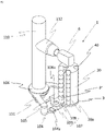
- FIG. 6 shows a complete multifunction scale M with a dropping device 1 according to any embodiment of the present invention as a sectional view.
- a section through the entire unit consisting of multihead weigher M, distribution plate V, storage containers VB and weighing containers WB arranged underneath, collecting hopper T and packaging device E is shown.
- a metal detector MD is present between the collection funnel T and the packaging device E.
- the typical path of the product through the multihead weigher and the packaging device is indicated by a dotted line.
- test specimens can be returned from the packaging unit E to the ejection device 1 by the return device 9 .
- This can be done pneumatically, magnetically or mechanically, for example.
- specimens can after the passage of the metal detector MD and a completed testing process Process can be removed again, and can thus be conveyed back to their starting point, i.e. to magazine 2.
- This enables a higher degree of automation up to full automation, and metal checks can also be planned over longer time units. Furthermore, this contributes to increased security.
- the magazine can have any shape; polygons, prisms or similar shapes are also possible.
Landscapes
- Life Sciences & Earth Sciences (AREA)
- Engineering & Computer Science (AREA)
- Physics & Mathematics (AREA)
- Geophysics (AREA)
- Remote Sensing (AREA)
- General Life Sciences & Earth Sciences (AREA)
- General Physics & Mathematics (AREA)
- Environmental & Geological Engineering (AREA)
- Geology (AREA)
- Electromagnetism (AREA)
- Manufacturing & Machinery (AREA)
- Basic Packing Technique (AREA)
- Geophysics And Detection Of Objects (AREA)
- Sorting Of Articles (AREA)
Claims (15)
- Dispositif d'éjection (1) pour des corps d'essai (P) pour des systèmes de détection de métaux pour des balances à têtes multiples (M), présentant :au moins un magasin (2, 20), lequel est adapté pour recevoir à l'intérieur au moins un corps d'essai (P),dans lequel au moins deux ouvertures de palier de corps d'essai (4, 4' ; 40, 40') sont prévues dans le magasin (2, 20), lesquelles s'étendent à travers le magasin (2, 20) de haut en bas ;un dispositif de limitation (3) qui est agencé en dessous du magasin (2),caractérisé en ce que le dispositif de limitation (3) présente un évidement (3a) qui présente au moins la même section transversale qu'un corps d'essai (P) ; ainsi que le dispositif d'éjection (1) présente un entraînement (5) qui est adapté afin de déplacer le magasin (2, 20) de sorte que différentes ouvertures de palier de corps d'essai (4, 4' ; 40, 40') puissent être positionnées au-dessus de l'évidement (3a) du dispositif de limitation (3).
- Dispositif d'éjection (1) selon la revendication 1, dans lequel les au moins deux ouvertures de palier de corps d'essai (4, 4a ; 40, 40') sont prévues de sorte que leurs points médians se situent sur un cercle, et l'entraînement (5) est adapté afin de tourner le magasin (2, 20) autour du point médian du cercle.
- Dispositif d'éjection (1) selon la revendication 1 ou 2, présentant en outre au moins un premier capteur (6) qui est adapté afin de détecter la présence et/ou les propriétés de corps d'essai (P) qui sont prévus dans le magasin (2, 20).
- Dispositif d'éjection (1) selon la revendication 3, dans lequel le premier capteur (6) est un capteur de distance optique, dont le faisceau de lumière s'étend de préférence de manière parallèle par rapport à l'axe principal du magasin (2, 20).
- Dispositif d'éjection (1) selon l'une quelconque des revendications précédentes, présentant en outre un deuxième capteur (7) qui est adapté afin de détecter la teneur en métal et/ou la couleur des corps d'essai (P) logeant dans le magasin (2, 20).
- Dispositif d'éjection (1) selon l'une quelconque des revendications 3 à 5, présentant en outre une unité d'évaluation (10) qui est conçue afin de traiter les signaux de l'au moins un capteur (6, 7).
- Dispositif d'éjection (1) selon l'une quelconque des revendications précédentes, dans lequel le magasin (2, 20) présente au moins une ouverture latérale (2a, 20a) ou une section au moins en partie translucide qui est adaptée pour permettre une inspection visuelle optique de l'état de remplissage du magasin (2, 20).
- Dispositif d'éjection (1) selon l'une quelconque des revendications précédentes, dans lequel le magasin (2, 20) est adapté afin de recevoir dans une ouverture de palier de corps d'essai (4, 40) plusieurs corps d'essai (P) les uns au-dessus des autres.
- Dispositif d'éjection selon la revendication 8, dans lequel un dispositif de séparation (8) est prévu au niveau de l'évidement (3a) du dispositif de limitation (3).
- Dispositif d'éjection selon la revendication 9, dans lequel le dispositif de séparation (8) présente :un premier élément horizontal (104) avec une première ouverture (104a), laquelle présente au moins le diamètre d'un corps d'essai (P),un bras pivotant (105), lequel peut être déplacé entre au moins deux positions au moyen d'un entraînement (106),un dispositif de transport (107) pour des corps d'essai (P), lequel est relié au bras pivotant (105), lequel présente :un deuxième élément horizontal (108), lequel présente une deuxième ouverture (108a), laquelle présente au moins le diamètre d'un corps d'essai (P), dans lequel est fixé sous la deuxième ouverture (108a) un dispositif de logement (109),dans lequel la deuxième ouverture (108a) du deuxième élément horizontal (108) se trouve sous le magasin (2, 20) dans une première position (P1) que le bras pivotant (105) peut adopter de sorte qu'un corps d'essai (P) peut tomber dans le dispositif de logement (109) hors du magasin (2, 20) par la deuxième ouverture (108a) du deuxième élément horizontal (108),dans lequel le dispositif de logement (109) se trouve au-dessus de la première ouverture (104a) du premier élément horizontal (104) dans une deuxième position (P2) que le bras pivotant (105) peut adopter de sorte que le corps d'essai (P) se trouvant dans le dispositif de logement (109) peut être éjecté par la première ouverture (104a) du premier élément horizontal (104),dans lequel le deuxième élément horizontal (108) empêche, dans chaque position, autre que la première position (P1), du bras pivotant (105), la chute ultérieure d'autres corps d'essai (P) hors du magasin (2, 20).
- Système composé d'un dispositif d'éjection (1) selon l'une quelconque des revendications 1 à 9, d'au moins un corps d'essai (P) et d'une balance à têtes multiples (M), qui présente entre autres un plateau de distribution (V), plusieurs contenants de pesage (WB), une trémie de collecte (T), une unité d'emballage (E) ainsi qu'un détecteur de métaux (MD) ainsi qu'en option plusieurs réservoirs (VB),dans lequel l'évidement (3a) du dispositif d'éjection (1) est disposé au-dessus du plateau de distribution (V) ou d'un contenant de pesage (WB) ainsi qu'en option des réservoirs (VB) de la balance à têtes multiples (M),et le détecteur de métaux (MD) est prévu sur ou à proximité de la trémie de collecte (T) ou de l'unité d'emballage (E).
- Système composé d'un dispositif d'éjection (1) selon la revendication 10, d'au moins un corps d'essai (P) et d'une balance à têtes multiples (M), qui présente entre autres un plateau de distribution (V), plusieurs contenants de pesage (WB), une trémie de collecte (T), une unité d'emballage (E) ainsi qu'un détecteur de métaux (MD),dans lequel la première ouverture (4a) du premier élément horizontal (4) du dispositif d'éjection (1) est disposée au-dessus du plateau de distribution (V) ou d'un contenant de pesage (WB) de la balance à têtes multiples (M),et le détecteur de métaux (MD) est prévu sur ou à proximité de la trémie de collecte (T) ou de l'unité d'emballage (E).
- Procédé pour tester un détecteur de métaux (MD) d'une balance à têtes multiples (M) ou d'une unité d'emballage (E) au moyen d'un dispositif d'éjection selon l'une quelconque des revendications 1 à 10, comprenant les étapes suivantes :a) vérification si un corps d'essai (P) est contenu dans le magasin (2, 20), en option si un corps d'essai (P) prévu pour l'éjection à venir est contenu ;b) si un résultat positif est atteint lors de l'étape a) : déplacement d'une ouverture de palier de corps d'essai (4, 40) qui contient un corps d'essai (P), au-dessus de l'évidement (3a) ; si un résultat négatif est obtenu lors de l'étape a) : demande de remplissage du magasin (2, 20) ;c) vérification si le détecteur de métaux (MD) de la balance à têtes multiples ou de l'unité d'emballage (E) détecte le corps d'essai (P) ; envoi et/ou mémorisation d'un résultat positif ou négatif.
- Procédé pour tester un détecteur de métaux (MD) d'une balance à têtes multiples (M) ou d'une unité d'emballage (E) au moyen d'un dispositif d'éjection selon l'une quelconque des revendications 8 à 10, comprenant les étapes suivantes :a) vérification si au moins un type de corps d'essai (P) est contenu dans le magasin (2, 20) dans une ouverture de palier de corps d'essai (4, 40), en option si un corps d'essai (P) prévu pour l'éjection à venir est contenu ;
en option : vérification si au moins un autre type de corps d'essai (P') est contenu dans le magasin (2, 20) dans une autre ouverture de palier de corps d'essai (4) ;b) détection de la quantité n de corps d'essai (P) dans l'une ouverture de palier de corps d'essai (4, 40) ;
en option : détection de la quantité m de corps d'essai (P') dans l'autre ouverture de palier de corps d'essai (4', 40') ;c) déplacement de l'une ouverture de palier de corps d'essai (4, 40) de sorte que celle-ci soit positionnée au-dessus de l'évidement (3a) ;d) éjection de corps d'essai (P) de l'une ouverture de palier de corps d'essai (4, 40) par actionnement du dispositif de séparation (8), dans lequel le dispositif de séparation (8) est actionné de préférence n fois, dans lequel un intervalle déterminé Δt se situe entre les éjections ;e) en option : déplacement de l'autre ouverture de palier de corps d'essai (4', 40') de sorte que celle-ci soit positionnée au-dessus de l'évidement (3a) ;f) éjection de corps d'essai (P') de l'autre ouverture de palier de corps d'essai (4, 40) par actionnement du dispositif de séparation (8), dans lequel le dispositif de séparation (8) est actionné de préférence m fois, dans lequel un intervalle déterminé Δt se situe entre les éjections. - Procédé selon l'une quelconque des revendications 13 ou 14, dans lequel des corps d'essai (P) sont transportés de nouveau de la balance à têtes multiples (M) ou de l'unité d'emballage (E) avec un dispositif de retour (9) dans le dispositif d'éjection (1) ou dans un magasin (2, 20) de celui-ci.
Applications Claiming Priority (1)
| Application Number | Priority Date | Filing Date | Title |
|---|---|---|---|
| EP19175923.2A EP3742205B1 (fr) | 2019-05-22 | 2019-05-22 | Détection de métaux dans des balances à têtes multiples |
Publications (2)
| Publication Number | Publication Date |
|---|---|
| EP3742206A1 EP3742206A1 (fr) | 2020-11-25 |
| EP3742206B1 true EP3742206B1 (fr) | 2022-05-18 |
Family
ID=66647029
Family Applications (2)
| Application Number | Title | Priority Date | Filing Date |
|---|---|---|---|
| EP19175923.2A Active EP3742205B1 (fr) | 2019-05-22 | 2019-05-22 | Détection de métaux dans des balances à têtes multiples |
| EP20176015.4A Active EP3742206B1 (fr) | 2019-05-22 | 2020-05-22 | Détection des métaux améliorée et étendue dans des peseuses à têtes multiples |
Family Applications Before (1)
| Application Number | Title | Priority Date | Filing Date |
|---|---|---|---|
| EP19175923.2A Active EP3742205B1 (fr) | 2019-05-22 | 2019-05-22 | Détection de métaux dans des balances à têtes multiples |
Country Status (2)
| Country | Link |
|---|---|
| EP (2) | EP3742205B1 (fr) |
| ES (2) | ES2887700T3 (fr) |
Families Citing this family (1)
| Publication number | Priority date | Publication date | Assignee | Title |
|---|---|---|---|---|
| CN113369179A (zh) * | 2021-05-31 | 2021-09-10 | 上海电机学院 | 一种电磁辅助抓取装置 |
Family Cites Families (11)
| Publication number | Priority date | Publication date | Assignee | Title |
|---|---|---|---|---|
| US4726434A (en) | 1986-07-28 | 1988-02-23 | Package Machinery Company | Metal detector testing process and apparatus in a combination weighing system |
| EP1217344A1 (fr) * | 1994-08-26 | 2002-06-26 | Anritsu Corporation | Dispositif de pesage combinatoire |
| JP3560703B2 (ja) * | 1995-09-01 | 2004-09-02 | 日新電子工業株式会社 | 金属検出装置 |
| GB0012994D0 (en) | 2000-05-26 | 2000-07-19 | Ishida Seisakusho | Article handling system |
| JP4570820B2 (ja) * | 2001-07-03 | 2010-10-27 | 株式会社イシダ | 金属検出装置 |
| JP2005049300A (ja) * | 2003-07-31 | 2005-02-24 | Yamato Scale Co Ltd | 金属検出装置 |
| JP3902584B2 (ja) * | 2003-10-10 | 2007-04-11 | 株式会社イシダ | 計量装置およびこれを備えた組合せ計量装置 |
| WO2009084964A2 (fr) * | 2008-01-02 | 2009-07-09 | Telenor Asa | Distributeur de balle |
| WO2011051934A1 (fr) * | 2009-10-27 | 2011-05-05 | Gil Ozmo | Appareil de distribution d'objets sur un substrat |
| GB2486939B (en) * | 2011-12-01 | 2012-11-21 | Data Detection Technologies Ltd | Method and apparatus for dispensing items |
| US10906682B2 (en) * | 2016-03-10 | 2021-02-02 | Kellogg Company | Food processing system, apparatus for testing a foreign object sensor and a method for operating the food processing system |
-
2019
- 2019-05-22 ES ES19175923T patent/ES2887700T3/es active Active
- 2019-05-22 EP EP19175923.2A patent/EP3742205B1/fr active Active
-
2020
- 2020-05-22 ES ES20176015T patent/ES2919656T3/es active Active
- 2020-05-22 EP EP20176015.4A patent/EP3742206B1/fr active Active
Also Published As
| Publication number | Publication date |
|---|---|
| ES2919656T3 (es) | 2022-07-27 |
| EP3742205B1 (fr) | 2021-06-30 |
| EP3742206A1 (fr) | 2020-11-25 |
| ES2887700T3 (es) | 2021-12-27 |
| EP3742205A1 (fr) | 2020-11-25 |
Similar Documents
| Publication | Publication Date | Title |
|---|---|---|
| DE69635547T2 (de) | Verfahren und einrichtung zum wiegen von kombinationen | |
| DE69611128T2 (de) | Verfahren und Vorrichtung zum Sortieren von Poststücken unter Verwendung von Pufferbehältern bei den Sortierausgängen | |
| EP2089295B1 (fr) | Systeme de tri et de distribution | |
| DE102020214613B4 (de) | Vorrichtung und Verfahren zum Aufgeben von Transporttaschen in eine Fördertechnik einer Hängeförderanlage sowie derartige Hängeförderanlage | |
| DE60204001T2 (de) | Zuführbehälter für gegenstände | |
| DE69119885T2 (de) | Kombinationswaage mit grosser präzision für einen grossen produktbereich einschliesslich viskoser substanzen | |
| DE69807539T2 (de) | Automatisches Analysegerät | |
| DE69838392T2 (de) | Sortierer nach gewicht | |
| DE19520191C2 (de) | Verfahren zur On-Line-Gewichtskontrolle von Kapseln | |
| DE4325569A1 (de) | Verfahren und Maschine zum Dosieren eines pharmazeutischen Produkts in Kapseln | |
| DE69317852T2 (de) | Teilmengenwaagen mit Taraberücksichtigungen einer verpackten Ware. | |
| DE69203848T2 (de) | Wiege- und Füllvorrichtung. | |
| DE69629148T2 (de) | Verfahren zum kombinatorischen Wägen nach Rang | |
| GB2061490A (en) | Sorting Coloured Gambling Chips | |
| DE69015329T2 (de) | Zufuhrvorrichtung für kleine teile. | |
| EP3742206B1 (fr) | Détection des métaux améliorée et étendue dans des peseuses à têtes multiples | |
| US4933074A (en) | Article singulating system and method | |
| DE102022100828B4 (de) | Vorrichtung für kleinvolumiges Schüttgut | |
| DE69409324T2 (de) | Becherwerkverteilsystem | |
| DE69603693T2 (de) | Einsatzformsystem | |
| DE69106210T2 (de) | Wursthandhabungs- und Verpackungsmaschine. | |
| DE3906728A1 (de) | Schnell arbeitende zufuehrvorrichtung fuer eine automatische verpackungsmaschine | |
| EP0003597B1 (fr) | Procédé et dispositif pour contrôler les emballages fermés quant à l'integralité de leur contenu | |
| DE20010323U1 (de) | Vorrichtung zur automatischen Qualitätskontrolle von Prüflingen | |
| DE19757963C2 (de) | Vorrichtung zum automatischen Kommissionieren von Stückgut |
Legal Events
| Date | Code | Title | Description |
|---|---|---|---|
| PUAI | Public reference made under article 153(3) epc to a published international application that has entered the european phase |
Free format text: ORIGINAL CODE: 0009012 |
|
| STAA | Information on the status of an ep patent application or granted ep patent |
Free format text: STATUS: THE APPLICATION HAS BEEN PUBLISHED |
|
| STAA | Information on the status of an ep patent application or granted ep patent |
Free format text: STATUS: REQUEST FOR EXAMINATION WAS MADE |
|
| AK | Designated contracting states |
Kind code of ref document: A1 Designated state(s): AL AT BE BG CH CY CZ DE DK EE ES FI FR GB GR HR HU IE IS IT LI LT LU LV MC MK MT NL NO PL PT RO RS SE SI SK SM TR |
|
| AX | Request for extension of the european patent |
Extension state: BA ME |
|
| 17P | Request for examination filed |
Effective date: 20201104 |
|
| RBV | Designated contracting states (corrected) |
Designated state(s): AL AT BE BG CH CY CZ DE DK EE ES FI FR GB GR HR HU IE IS IT LI LT LU LV MC MK MT NL NO PL PT RO RS SE SI SK SM TR |
|
| RIN1 | Information on inventor provided before grant (corrected) |
Inventor name: ZECK, WOLFRAM C. Inventor name: PETERS, ANDREAS |
|
| RIC1 | Information provided on ipc code assigned before grant |
Ipc: G01G 19/393 20060101ALN20211124BHEP Ipc: B65B 1/34 20060101ALN20211124BHEP Ipc: G01V 3/10 20060101ALI20211124BHEP Ipc: G01V 13/00 20060101AFI20211124BHEP |
|
| GRAP | Despatch of communication of intention to grant a patent |
Free format text: ORIGINAL CODE: EPIDOSNIGR1 |
|
| STAA | Information on the status of an ep patent application or granted ep patent |
Free format text: STATUS: GRANT OF PATENT IS INTENDED |
|
| RIC1 | Information provided on ipc code assigned before grant |
Ipc: G01G 19/393 20060101ALN20211213BHEP Ipc: B65B 1/34 20060101ALN20211213BHEP Ipc: G01V 3/10 20060101ALI20211213BHEP Ipc: G01V 13/00 20060101AFI20211213BHEP |
|
| INTG | Intention to grant announced |
Effective date: 20220118 |
|
| GRAS | Grant fee paid |
Free format text: ORIGINAL CODE: EPIDOSNIGR3 |
|
| GRAA | (expected) grant |
Free format text: ORIGINAL CODE: 0009210 |
|
| STAA | Information on the status of an ep patent application or granted ep patent |
Free format text: STATUS: THE PATENT HAS BEEN GRANTED |
|
| RIN1 | Information on inventor provided before grant (corrected) |
Inventor name: ZECK, WOLFRAM C. Inventor name: PETERS, ANDREAS Inventor name: KRAEMER, L. WILHELM |
|
| AK | Designated contracting states |
Kind code of ref document: B1 Designated state(s): AL AT BE BG CH CY CZ DE DK EE ES FI FR GB GR HR HU IE IS IT LI LT LU LV MC MK MT NL NO PL PT RO RS SE SI SK SM TR |
|
| REG | Reference to a national code |
Ref country code: GB Ref legal event code: FG4D Free format text: NOT ENGLISH |
|
| REG | Reference to a national code |
Ref country code: CH Ref legal event code: EP |
|
| REG | Reference to a national code |
Ref country code: IE Ref legal event code: FG4D Free format text: LANGUAGE OF EP DOCUMENT: GERMAN |
|
| REG | Reference to a national code |
Ref country code: DE Ref legal event code: R096 Ref document number: 502020001117 Country of ref document: DE |
|
| REG | Reference to a national code |
Ref country code: AT Ref legal event code: REF Ref document number: 1493484 Country of ref document: AT Kind code of ref document: T Effective date: 20220615 |
|
| REG | Reference to a national code |
Ref country code: ES Ref legal event code: FG2A Ref document number: 2919656 Country of ref document: ES Kind code of ref document: T3 Effective date: 20220727 |
|
| REG | Reference to a national code |
Ref country code: NL Ref legal event code: FP |
|
| REG | Reference to a national code |
Ref country code: LT Ref legal event code: MG9D |
|
| PG25 | Lapsed in a contracting state [announced via postgrant information from national office to epo] |
Ref country code: SE Free format text: LAPSE BECAUSE OF FAILURE TO SUBMIT A TRANSLATION OF THE DESCRIPTION OR TO PAY THE FEE WITHIN THE PRESCRIBED TIME-LIMIT Effective date: 20220518 Ref country code: PT Free format text: LAPSE BECAUSE OF FAILURE TO SUBMIT A TRANSLATION OF THE DESCRIPTION OR TO PAY THE FEE WITHIN THE PRESCRIBED TIME-LIMIT Effective date: 20220919 Ref country code: NO Free format text: LAPSE BECAUSE OF FAILURE TO SUBMIT A TRANSLATION OF THE DESCRIPTION OR TO PAY THE FEE WITHIN THE PRESCRIBED TIME-LIMIT Effective date: 20220818 Ref country code: LT Free format text: LAPSE BECAUSE OF FAILURE TO SUBMIT A TRANSLATION OF THE DESCRIPTION OR TO PAY THE FEE WITHIN THE PRESCRIBED TIME-LIMIT Effective date: 20220518 Ref country code: HR Free format text: LAPSE BECAUSE OF FAILURE TO SUBMIT A TRANSLATION OF THE DESCRIPTION OR TO PAY THE FEE WITHIN THE PRESCRIBED TIME-LIMIT Effective date: 20220518 Ref country code: GR Free format text: LAPSE BECAUSE OF FAILURE TO SUBMIT A TRANSLATION OF THE DESCRIPTION OR TO PAY THE FEE WITHIN THE PRESCRIBED TIME-LIMIT Effective date: 20220819 Ref country code: FI Free format text: LAPSE BECAUSE OF FAILURE TO SUBMIT A TRANSLATION OF THE DESCRIPTION OR TO PAY THE FEE WITHIN THE PRESCRIBED TIME-LIMIT Effective date: 20220518 Ref country code: BG Free format text: LAPSE BECAUSE OF FAILURE TO SUBMIT A TRANSLATION OF THE DESCRIPTION OR TO PAY THE FEE WITHIN THE PRESCRIBED TIME-LIMIT Effective date: 20220818 |
|
| PG25 | Lapsed in a contracting state [announced via postgrant information from national office to epo] |
Ref country code: RS Free format text: LAPSE BECAUSE OF FAILURE TO SUBMIT A TRANSLATION OF THE DESCRIPTION OR TO PAY THE FEE WITHIN THE PRESCRIBED TIME-LIMIT Effective date: 20220518 Ref country code: PL Free format text: LAPSE BECAUSE OF FAILURE TO SUBMIT A TRANSLATION OF THE DESCRIPTION OR TO PAY THE FEE WITHIN THE PRESCRIBED TIME-LIMIT Effective date: 20220518 Ref country code: LV Free format text: LAPSE BECAUSE OF FAILURE TO SUBMIT A TRANSLATION OF THE DESCRIPTION OR TO PAY THE FEE WITHIN THE PRESCRIBED TIME-LIMIT Effective date: 20220518 Ref country code: IS Free format text: LAPSE BECAUSE OF FAILURE TO SUBMIT A TRANSLATION OF THE DESCRIPTION OR TO PAY THE FEE WITHIN THE PRESCRIBED TIME-LIMIT Effective date: 20220918 |
|
| REG | Reference to a national code |
Ref country code: BE Ref legal event code: MM Effective date: 20220531 |
|
| PG25 | Lapsed in a contracting state [announced via postgrant information from national office to epo] |
Ref country code: SM Free format text: LAPSE BECAUSE OF FAILURE TO SUBMIT A TRANSLATION OF THE DESCRIPTION OR TO PAY THE FEE WITHIN THE PRESCRIBED TIME-LIMIT Effective date: 20220518 Ref country code: SK Free format text: LAPSE BECAUSE OF FAILURE TO SUBMIT A TRANSLATION OF THE DESCRIPTION OR TO PAY THE FEE WITHIN THE PRESCRIBED TIME-LIMIT Effective date: 20220518 Ref country code: RO Free format text: LAPSE BECAUSE OF FAILURE TO SUBMIT A TRANSLATION OF THE DESCRIPTION OR TO PAY THE FEE WITHIN THE PRESCRIBED TIME-LIMIT Effective date: 20220518 Ref country code: LU Free format text: LAPSE BECAUSE OF NON-PAYMENT OF DUE FEES Effective date: 20220522 Ref country code: EE Free format text: LAPSE BECAUSE OF FAILURE TO SUBMIT A TRANSLATION OF THE DESCRIPTION OR TO PAY THE FEE WITHIN THE PRESCRIBED TIME-LIMIT Effective date: 20220518 Ref country code: DK Free format text: LAPSE BECAUSE OF FAILURE TO SUBMIT A TRANSLATION OF THE DESCRIPTION OR TO PAY THE FEE WITHIN THE PRESCRIBED TIME-LIMIT Effective date: 20220518 Ref country code: CZ Free format text: LAPSE BECAUSE OF FAILURE TO SUBMIT A TRANSLATION OF THE DESCRIPTION OR TO PAY THE FEE WITHIN THE PRESCRIBED TIME-LIMIT Effective date: 20220518 |
|
| REG | Reference to a national code |
Ref country code: DE Ref legal event code: R097 Ref document number: 502020001117 Country of ref document: DE |
|
| PG25 | Lapsed in a contracting state [announced via postgrant information from national office to epo] |
Ref country code: MC Free format text: LAPSE BECAUSE OF FAILURE TO SUBMIT A TRANSLATION OF THE DESCRIPTION OR TO PAY THE FEE WITHIN THE PRESCRIBED TIME-LIMIT Effective date: 20220518 |
|
| PLBE | No opposition filed within time limit |
Free format text: ORIGINAL CODE: 0009261 |
|
| STAA | Information on the status of an ep patent application or granted ep patent |
Free format text: STATUS: NO OPPOSITION FILED WITHIN TIME LIMIT |
|
| PG25 | Lapsed in a contracting state [announced via postgrant information from national office to epo] |
Ref country code: AL Free format text: LAPSE BECAUSE OF FAILURE TO SUBMIT A TRANSLATION OF THE DESCRIPTION OR TO PAY THE FEE WITHIN THE PRESCRIBED TIME-LIMIT Effective date: 20220518 |
|
| 26N | No opposition filed |
Effective date: 20230221 |
|
| PG25 | Lapsed in a contracting state [announced via postgrant information from national office to epo] |
Ref country code: IE Free format text: LAPSE BECAUSE OF NON-PAYMENT OF DUE FEES Effective date: 20220522 |
|
| PG25 | Lapsed in a contracting state [announced via postgrant information from national office to epo] |
Ref country code: SI Free format text: LAPSE BECAUSE OF FAILURE TO SUBMIT A TRANSLATION OF THE DESCRIPTION OR TO PAY THE FEE WITHIN THE PRESCRIBED TIME-LIMIT Effective date: 20220518 Ref country code: BE Free format text: LAPSE BECAUSE OF NON-PAYMENT OF DUE FEES Effective date: 20220531 |
|
| P01 | Opt-out of the competence of the unified patent court (upc) registered |
Effective date: 20230710 |
|
| REG | Reference to a national code |
Ref country code: CH Ref legal event code: PL |
|
| PG25 | Lapsed in a contracting state [announced via postgrant information from national office to epo] |
Ref country code: LI Free format text: LAPSE BECAUSE OF NON-PAYMENT OF DUE FEES Effective date: 20230531 Ref country code: IT Free format text: LAPSE BECAUSE OF FAILURE TO SUBMIT A TRANSLATION OF THE DESCRIPTION OR TO PAY THE FEE WITHIN THE PRESCRIBED TIME-LIMIT Effective date: 20220518 Ref country code: CH Free format text: LAPSE BECAUSE OF NON-PAYMENT OF DUE FEES Effective date: 20230531 |
|
| PG25 | Lapsed in a contracting state [announced via postgrant information from national office to epo] |
Ref country code: MK Free format text: LAPSE BECAUSE OF FAILURE TO SUBMIT A TRANSLATION OF THE DESCRIPTION OR TO PAY THE FEE WITHIN THE PRESCRIBED TIME-LIMIT Effective date: 20220511 Ref country code: CY Free format text: LAPSE BECAUSE OF FAILURE TO SUBMIT A TRANSLATION OF THE DESCRIPTION OR TO PAY THE FEE WITHIN THE PRESCRIBED TIME-LIMIT Effective date: 20220511 |
|
| PG25 | Lapsed in a contracting state [announced via postgrant information from national office to epo] |
Ref country code: HU Free format text: LAPSE BECAUSE OF FAILURE TO SUBMIT A TRANSLATION OF THE DESCRIPTION OR TO PAY THE FEE WITHIN THE PRESCRIBED TIME-LIMIT; INVALID AB INITIO Effective date: 20200522 |
|
| PGFP | Annual fee paid to national office [announced via postgrant information from national office to epo] |
Ref country code: NL Payment date: 20240527 Year of fee payment: 5 |
|
| PGFP | Annual fee paid to national office [announced via postgrant information from national office to epo] |
Ref country code: GB Payment date: 20240521 Year of fee payment: 5 |
|
| PGFP | Annual fee paid to national office [announced via postgrant information from national office to epo] |
Ref country code: DE Payment date: 20240528 Year of fee payment: 5 |
|
| PGFP | Annual fee paid to national office [announced via postgrant information from national office to epo] |
Ref country code: ES Payment date: 20240614 Year of fee payment: 5 |
|
| PGFP | Annual fee paid to national office [announced via postgrant information from national office to epo] |
Ref country code: FR Payment date: 20240523 Year of fee payment: 5 |
|
| PG25 | Lapsed in a contracting state [announced via postgrant information from national office to epo] |
Ref country code: MT Free format text: LAPSE BECAUSE OF FAILURE TO SUBMIT A TRANSLATION OF THE DESCRIPTION OR TO PAY THE FEE WITHIN THE PRESCRIBED TIME-LIMIT Effective date: 20220511 |
|
| PG25 | Lapsed in a contracting state [announced via postgrant information from national office to epo] |
Ref country code: BG Free format text: LAPSE BECAUSE OF FAILURE TO SUBMIT A TRANSLATION OF THE DESCRIPTION OR TO PAY THE FEE WITHIN THE PRESCRIBED TIME-LIMIT Effective date: 20220518 |
|
| PG25 | Lapsed in a contracting state [announced via postgrant information from national office to epo] |
Ref country code: BG Free format text: LAPSE BECAUSE OF FAILURE TO SUBMIT A TRANSLATION OF THE DESCRIPTION OR TO PAY THE FEE WITHIN THE PRESCRIBED TIME-LIMIT Effective date: 20220518 |
|
| PGFP | Annual fee paid to national office [announced via postgrant information from national office to epo] |
Ref country code: AT Payment date: 20250721 Year of fee payment: 5 |
|
| REG | Reference to a national code |
Ref country code: DE Ref legal event code: R119 Ref document number: 502020001117 Country of ref document: DE |
|
| PG25 | Lapsed in a contracting state [announced via postgrant information from national office to epo] |
Ref country code: TR Free format text: LAPSE BECAUSE OF FAILURE TO SUBMIT A TRANSLATION OF THE DESCRIPTION OR TO PAY THE FEE WITHIN THE PRESCRIBED TIME-LIMIT Effective date: 20220518 |
|
| REG | Reference to a national code |
Ref country code: NL Ref legal event code: MM Effective date: 20250601 |
|
| GBPC | Gb: european patent ceased through non-payment of renewal fee |
Effective date: 20250522 |
|
| PG25 | Lapsed in a contracting state [announced via postgrant information from national office to epo] |
Ref country code: NL Free format text: LAPSE BECAUSE OF NON-PAYMENT OF DUE FEES Effective date: 20250601 |
|
| PG25 | Lapsed in a contracting state [announced via postgrant information from national office to epo] |
Ref country code: GB Free format text: LAPSE BECAUSE OF NON-PAYMENT OF DUE FEES Effective date: 20250522 |
|
| PG25 | Lapsed in a contracting state [announced via postgrant information from national office to epo] |
Ref country code: DE Free format text: LAPSE BECAUSE OF NON-PAYMENT OF DUE FEES Effective date: 20251202 |
|
| PG25 | Lapsed in a contracting state [announced via postgrant information from national office to epo] |
Ref country code: FR Free format text: LAPSE BECAUSE OF NON-PAYMENT OF DUE FEES Effective date: 20250531 |