EP3744913A1 - Outil de montage d'un joint annulaire sur un couvercle d'égout - Google Patents
Outil de montage d'un joint annulaire sur un couvercle d'égout Download PDFInfo
- Publication number
- EP3744913A1 EP3744913A1 EP19176907.4A EP19176907A EP3744913A1 EP 3744913 A1 EP3744913 A1 EP 3744913A1 EP 19176907 A EP19176907 A EP 19176907A EP 3744913 A1 EP3744913 A1 EP 3744913A1
- Authority
- EP
- European Patent Office
- Prior art keywords
- sealing
- tool
- arm
- sewer cover
- rim
- Prior art date
- Legal status (The legal status is an assumption and is not a legal conclusion. Google has not performed a legal analysis and makes no representation as to the accuracy of the status listed.)
- Withdrawn
Links
- 238000007789 sealing Methods 0.000 title claims abstract description 140
- 238000000034 method Methods 0.000 claims description 10
- 238000006073 displacement reaction Methods 0.000 claims description 3
- 239000010865 sewage Substances 0.000 description 9
- XEEYBQQBJWHFJM-UHFFFAOYSA-N Iron Chemical compound [Fe] XEEYBQQBJWHFJM-UHFFFAOYSA-N 0.000 description 4
- 238000004140 cleaning Methods 0.000 description 4
- 229910052742 iron Inorganic materials 0.000 description 2
- 229910001018 Cast iron Inorganic materials 0.000 description 1
- 230000009286 beneficial effect Effects 0.000 description 1
- 230000000694 effects Effects 0.000 description 1
- 238000007689 inspection Methods 0.000 description 1
- 230000000149 penetrating effect Effects 0.000 description 1
- 229920000642 polymer Polymers 0.000 description 1
- 230000002035 prolonged effect Effects 0.000 description 1
- 230000000284 resting effect Effects 0.000 description 1
Images


Classifications
-
- E—FIXED CONSTRUCTIONS
- E03—WATER SUPPLY; SEWERAGE
- E03F—SEWERS; CESSPOOLS
- E03F5/00—Sewerage structures
- E03F5/02—Manhole shafts or other inspection chambers; Snow-filling openings; accessories
-
- E—FIXED CONSTRUCTIONS
- E02—HYDRAULIC ENGINEERING; FOUNDATIONS; SOIL SHIFTING
- E02D—FOUNDATIONS; EXCAVATIONS; EMBANKMENTS; UNDERGROUND OR UNDERWATER STRUCTURES
- E02D29/00—Independent underground or underwater structures; Retaining walls
- E02D29/12—Manhole shafts; Other inspection or access chambers; Accessories therefor
- E02D29/14—Covers for manholes or the like; Frames for covers
- E02D29/149—Annular gaskets
-
- E—FIXED CONSTRUCTIONS
- E02—HYDRAULIC ENGINEERING; FOUNDATIONS; SOIL SHIFTING
- E02D—FOUNDATIONS; EXCAVATIONS; EMBANKMENTS; UNDERGROUND OR UNDERWATER STRUCTURES
- E02D29/00—Independent underground or underwater structures; Retaining walls
- E02D29/12—Manhole shafts; Other inspection or access chambers; Accessories therefor
- E02D29/14—Covers for manholes or the like; Frames for covers
- E02D29/1445—Tools for positioning or removing cover frames
Definitions
- the present invention relates in general to the field of sewer systems. More specifically, the present invention relates in a first aspect to a tool for mounting an annular sealing on the rim of a sewer cover, such as a road-type sewer cover. In a second aspect the present invention relates the use of such a tool for mounting an annular sealing on the rim of a sewer cover. In a third aspect the present invention relates to a method for mounting an annular sealing on the rim of a sewer cover.
- the sewer pipes usually follow streets and roads on their way to the sewage cleaning facility. As more and more sources of sewage are coupled to the sewer pipes along the path leading to the sewage cleaning facility, it is clear that a relatively large pass-through capacity of sewage is needed near the sewage cleaning facility.
- sewer pipes being dug into the ground under streets and roads are having an inner diameter of up to 250 cm or even more.
- an entrance into the sewer pipe system is needed.
- Such entrances are typically provided at the surface of the roads and streets at regular mutual distances and the entrances comprises a passage leading in a vertical direction from the level of the road or street down to an upper opening in a horizontally arranged sewer pipe of the sewer pipe system.
- the entrances are at the level of the road or street covered with a sewer cover, such as a circular sewer cover resting on a support forming part of the vertical passage.
- a sewer cover such as a circular sewer cover resting on a support forming part of the vertical passage.
- the covers as well as their corresponding supports are typically being made from cast iron.
- the rim of the covers is being provided with an annular sealing, such as a rubber sealing.
- the sealing will accordingly cover a part of a lower surface of the rim of the sewer cover as well as the outer periphery thereof.
- Such sealings provided on the rim of the sewage covers efficiently reduce the amount of noise which would otherwise have been produced by heavy vehicles driving over the covers.
- the first aspect of the present invention relates to a tool for mounting an annular sealing on the rim of a sewer cover; wherein said tool in the orientation intended during operation in a situation where said sewer cover is horizontally arranged, comprises:
- the present invention relates to a use of a tool according to the first aspect for mounting a sealing on the rim of a sewer cover.
- the present invention relates to a method for mounting a sealing on the rim of a sewer cover; said method comprises the steps of:
- the present invention in its various aspects provides for a faster, more efficient and more safe mode of mounting a sealing on the rim of a sewer cover. Moreover, the invention in its various aspects allows for mounting a sealing on the rim of a sewer cover even singlehanded.
- the first aspect of the present invention relates to a tool for mounting an annular sealing on the rim of a sewer cover; wherein said tool in the orientation intended during operation in a situation where said sewer cover is horizontally arranged, comprises:
- the arm comprises a sealing guide which aids in guiding a sealing into place on the rim of a sewer cover as explained in much more detail below.
- said base at a lower surface thereof, comprises one or more engagement means protruding from said lower surface in a downward direction so as to enable said engagement means to enter into engagement with a lifting hole being present in said sewer cover .
- said engagement means is in the form of a hook, such as an arched hook or an L-shaped hook.
- a hook-shaped engagement means will provide for sufficiently good engagement with the sewer cover in order to ensure fixation of the tool to the cover.
- said base comprises a primary part and one or more secondary parts, wherein in respect of one or more of said secondary parts, said primary part and said secondary part comprises adjustment means for adjusting the distance of the engagement means, in a radial direction, from said swivel axis.
- said adjustment means comprises oblong, through going holes being present in said primary part and/or said secondary part of said base, and wherein the position of said primary part of said base relative to said secondary part of said base thereby can be adjusted and finally be fixed to each other, such as by means of nuts and bolts.
- Providing the base with sch adjustment means allows the tool to be suitable for use with various types and sizes of sewer covers.
- said first connecting element comprises an inner cylinder having a circular cross-section; and said second connecting element comprises an outer cylinder having a circular cross-section, wherein said outer cylinder is being configured for being accommodated in said inner cylinder; or alternatively said first connecting element comprises an outer cylinder having a circular cross-section; and said second connecting element comprises an inner cylinder having a circular cross-section, wherein said outer cylinder is being configured for being accommodated in said inner cylinder.
- the term “inner cylinder” and “outer cylinder”, respectively, may be construed to mean a cylinder having a concave cylindrical surface and a convex cylindrical surface, respectively.
- said first connecting element and said second connecting element are configured for being disconnected from each other.
- the tool may more easily be moved around and stowed away.
- said tool comprises a lock, such as a retaining pin in combination with a through-going hole in said outer cylinder, such as in said first connecting element, for preventing that said first connecting element and said second connecting element disconnect from each other once in a connecting configuration with each other.
- a lock such as a retaining pin in combination with a through-going hole in said outer cylinder, such as in said first connecting element, for preventing that said first connecting element and said second connecting element disconnect from each other once in a connecting configuration with each other.
- said sealing guide comprises displacement adjustment means for allowing said sealing guide to be arranged on said arm at various distances D from the swiveling axis; and wherein said sealing guide furthermore comprises fixing means for fixing said sealing guide at a desired distance from the swiveling axis.
- the tool is suitable for use for mounting a sealing on sewer covers of various types, sizes and designs.
- said protrusion of said sealing guide comprises a horizontally arranged flange.
- the flange will prevent movement in a vertical direction of the sealing upon being fitted to the rim of a sewer cover, and thereby will help in guiding the sealing into place.
- said sealing guide comprises a bulge comprising a rounded surface for aiding in guiding the sealing during operation of said tool.
- said protrusion of said sealing guide comprises height adjustment means for adjusting and fixing the position, in a vertical direction, of said protrusion relative to said arm.
- the vertical position of the protrusion may be adjusted which may aid in obtaining, in respect of a given size and type of sewer cover, an optimum setting of the tool.
- said base comprises two bars being connected to each other at an angle of approximately 90°.
- said protrusion extends from said arm in a downward direction at an angle A relative to a plane P defined by the swiveling movement of said arm of 25 - 90°, such as 30 - 85°, for example 35 - 80°, such as 40 - 75°, e.g. 45 - 70°, such as 50 - 65°, e.g. 55 - 60°.
- the dimensions of said tool is configured for allowing the distance D to be selected in the range of 150 - 400 mm, such as 175 - 350 mm, such as 200 - 325 mm, e.g. 225 - 300 mm, for example 250 - 275 mm.
- the tool will be useful for use with sewer cover of various sizes.
- At least part of said protrusion being tapered in a downward direction, such as being tapered in a downward direction in a region between the flange and the bulge, if being present.
- Providing the tool with a protrusion being tapered in a downward direction aids in guiding the sealing into place on the rim of the sewer cover.
- the present invention relates to a use of a tool according to the first aspect for mounting a sealing on the rim of a sewer cover.
- the present invention relates to a method for mounting a sealing on the rim of a sewer cover; said method comprises the steps of:
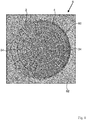
- fig. 1 is a photograph of a road type sewer cover, shot from above. It is seen in Fig. 1 that the sewer cover 6 is provided with a sealing 2 at a rim 4 thereof. The sewer cover 6 rests on a sewer cover support 60 being arranged in a road 62 and being in level with the road.
- the sewer cover is provided with two lifting holes 34 for aiding in lifting the cover from the road.
- Fig. 2 is a cross-sectional view illustrating a sewer cover being provided with an annular sealing at an outer rim thereof. In Fig. 2 is seen the tight fit of the sealing 2 at the rim 4 of the sewer cover 6.
- Fig. 2 also shows that a lower part of the rim 4 is covered with the seal 2.
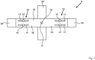
- Fig. 3 is a top view illustrating the base of the tool according to the present invention.
- the base 8 comprises two bars 56,56' being connected to each other at an angle of approximately 90°.
- the bar 56 itself comprises a primary part 36 and two secondary parts 38.
- the position of each secondary part 38, relative to the primary part 36 can be adjusted via the adjustment means 40.
- the primary part 36 comprises the bars 56 and 56'.
- Fig. 3 also illustrates that the primary part 36 is provided with a first connecting element 20 in the form of an outer cylinder.
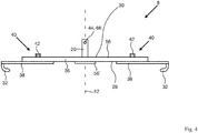
- Fig. 4 is a side view illustrating the base of the tool shown in Fig. 3 .
- Fig. 4 shows the base 8 comprising the two bars 56,56' being connected to each other.
- the primary part 36 of the base at each of its two opposite ends are prolonged by the presence of secondary parts 38.
- Each secondary part 38 near its outer end comprises, at a lower surface thereof, a engagement means 32 in the form of an arched hook.
- Each engagement means 32 is being configured to enter into the lifting holes 34 of the sewer cover 6 illustrated in Fig. 1 .
- the adjustment means 40 allows adjustment of the distance between the engagement means 32 and the swivel axis 12 of the arm of the tool which is to be arranged on the first connecting element 20 of the base 8.
- Fig. 5 is a side view illustrating an arm of the tool according to the present invention.
- the arm of the tool is configured to be arranged in a swiveling arrangement relative to the base of the tool.
- Fig. 5 shows the arm 10 of the tool 100 according to the present invention.
- the arm 10 comprises a first end 16 and a second end 18.
- the second connecting element 22 is in the form of a hollow or inner cylinder which is being adapted to fit onto the first connecting element 20 illustrated in Fig. 3 and 4 , in such a way that the arm will be able to perform a swiveling movement relative to the base 8 around the swivel axis 12.
- the second end 18 of the arm 10 is provided with a handle 24 for manually swiveling the arm 10 around the swivel axis 12.
- the sealing guide comprises a sliding element 47 which is being configured to slide along a longitudinal direction of the arm 10.
- Fixing means 48 in the form of a bolt which is screwed into the sliding element 47 allows for fixing the position of the sealing guide relative to the arm.
- the sealing guide also comprises a protrusion 26 extending from the arm in a downward direction.
- the angle A between the longitudinal extension of the protrusion in relation to a plane P defined by the swiveling movement of said arm 10 is approximately 90°.
- the position of the protrusion may be adjusted in a vertical direction. This is brought about by the height adjustment means 54 for adjusting and fixing the position, in a vertical direction, of said protrusion relative to said arm 10.
- the height adjustment means 54 is in a form of a bolt fixing the protrusion 26 relative to a remainder part of the sealing guide.
- a horizontally arranged flange 50 is provided at an upper part of the protrusion 26. This flange serves the purpose of preventing the sealing from slipping the sealing guide in an upward direction.
- a bulge 52 comprising a rounded surface and being arranged below the flange 50.
- the bulge 52 aids in guiding the sealing 2 during operation of said tool.
- Fig. 5 also illustrates how the distance D between the sealing guide 14 and the swivel axis 12 is defined, viz. as the horizontal distance between the swivel axis 12 and a lower end of the protrusion 26 of the sealing guide 14.
- Fig. 5 is illustrated the position of the plane P, as defined as the plane in which the rotation of the arm 10 around the swivel axis 12 is taken place.
- Fig. 6 is a side view illustrating the tool according to the present invention.
- Fig. 6 shows the tool 100 comprising the base 8 and the arm 10 with its sealing guide 14 arranged thereupon.
- the base 8 comprises a first connecting element 20 in the form of an outer cylinder and that that the first end of the arm 16 comprises a second connecting element 22 in the form of an inner cylinder.
- the first connecting element 20 has entered into a swiveling engagement with the second connecting element 22.
- the arm 10 of the tool is able to swivel in a plane P around the swivel axis 12.
- Fig. 6 also illustrates the meaning of the angle A as being the angle between a longitudinal direction of the protrusion 26 and a plane being perpendicular to the plane P.
- Fig. 7 is a partly cross-sectional view and partly side view illustrating the tool according to the present invention in a mounting operation.
- Fig. 7 shows in a cross-sectional view the sewer cover 6 and a sealing 2.
- Fig 7 shows the tool 100 comprising the base 8, the arm 10 and the sealing guide 14.
- Fig. 7 shows the tool 100 has being arranged on top of the sewer cover 6 in such a way that the swivel axis 12 is approximately arranged at the center of the cover 6 and in such a way that a lower part of the protrusion 26 of the sealing guide 14 is arranged at a larger radius than the radius corresponding to the rim 4 of the sewer cover 6 and approximately at the level of a lower part of said rim.
- the stretching of the sealing 2 has slightly deformed the geometry of the sealing at the position of the protrusion 26.
- the handle 24 of the arm 10 may now be swiveled around the swivel axis 12.
- the sealing guide will have guided the sealing fully into place and in this situation the sealing guide 14 and the tool may be removed from the sewer cover 6, and the sewer cover 6 will subsequently be provided with a sealing 2 as illustrated in Fig. 2 .
- FIG. 7 illustrates how the arm 10 and the second connecting element 22 is being locked, in a swiveling fashion, to the second connecting element 22 of the base 8 via a lock 44 in the form of a pin 64 penetrating a through-going hole 66 in said first connecting element 20, thereby preventing that the first connecting element 20 and the second connecting element 22 disconnect from each other once in a connecting configuration with each other.
Landscapes
- Engineering & Computer Science (AREA)
- Life Sciences & Earth Sciences (AREA)
- Civil Engineering (AREA)
- General Life Sciences & Earth Sciences (AREA)
- Mining & Mineral Resources (AREA)
- Paleontology (AREA)
- Environmental & Geological Engineering (AREA)
- General Engineering & Computer Science (AREA)
- Structural Engineering (AREA)
- Health & Medical Sciences (AREA)
- Hydrology & Water Resources (AREA)
- Public Health (AREA)
- Water Supply & Treatment (AREA)
- Sewage (AREA)
Priority Applications (1)
| Application Number | Priority Date | Filing Date | Title |
|---|---|---|---|
| EP19176907.4A EP3744913A1 (fr) | 2019-05-28 | 2019-05-28 | Outil de montage d'un joint annulaire sur un couvercle d'égout |
Applications Claiming Priority (1)
| Application Number | Priority Date | Filing Date | Title |
|---|---|---|---|
| EP19176907.4A EP3744913A1 (fr) | 2019-05-28 | 2019-05-28 | Outil de montage d'un joint annulaire sur un couvercle d'égout |
Publications (1)
| Publication Number | Publication Date |
|---|---|
| EP3744913A1 true EP3744913A1 (fr) | 2020-12-02 |
Family
ID=66668779
Family Applications (1)
| Application Number | Title | Priority Date | Filing Date |
|---|---|---|---|
| EP19176907.4A Withdrawn EP3744913A1 (fr) | 2019-05-28 | 2019-05-28 | Outil de montage d'un joint annulaire sur un couvercle d'égout |
Country Status (1)
| Country | Link |
|---|---|
| EP (1) | EP3744913A1 (fr) |
Cited By (1)
| Publication number | Priority date | Publication date | Assignee | Title |
|---|---|---|---|---|
| CN114960765A (zh) * | 2022-06-17 | 2022-08-30 | 新疆塔建三五九建工有限责任公司 | 一种市政公路用高密封性井盖 |
Citations (6)
| Publication number | Priority date | Publication date | Assignee | Title |
|---|---|---|---|---|
| DE3815365A1 (de) * | 1987-05-05 | 1989-08-17 | Hoos Hubert Dipl Ing Fh | Einbauteil fuer schaechte und entwaesserungsteile und vorrichtung zur handhabung desselben |
| US6869249B2 (en) * | 2002-10-30 | 2005-03-22 | Stephen Calhoon | Adjusting device for installing a manhole ring onto a manhole |
| DE202008013095U1 (de) * | 2008-10-06 | 2009-01-02 | Buderus Kanalguss Gmbh | Vorrichtung zur Justierung der Einbauhöhe von Schachtrahmen |
| US8043041B1 (en) * | 1995-06-12 | 2011-10-25 | Neeley Alvin L | Manhole cover lifting apparatus and method |
| KR101117206B1 (ko) * | 2009-07-15 | 2012-03-15 | 김준배 | 도난 방지기능을 갖는 맨홀뚜껑과, 이 맨홀뚜껑의 개방장치 |
| KR101418727B1 (ko) * | 2013-12-09 | 2014-07-11 | 주식회사 평강산업개발 | 맨홀보수장치 및 이를 이용한 맨홀보수방법 |
-
2019
- 2019-05-28 EP EP19176907.4A patent/EP3744913A1/fr not_active Withdrawn
Patent Citations (6)
| Publication number | Priority date | Publication date | Assignee | Title |
|---|---|---|---|---|
| DE3815365A1 (de) * | 1987-05-05 | 1989-08-17 | Hoos Hubert Dipl Ing Fh | Einbauteil fuer schaechte und entwaesserungsteile und vorrichtung zur handhabung desselben |
| US8043041B1 (en) * | 1995-06-12 | 2011-10-25 | Neeley Alvin L | Manhole cover lifting apparatus and method |
| US6869249B2 (en) * | 2002-10-30 | 2005-03-22 | Stephen Calhoon | Adjusting device for installing a manhole ring onto a manhole |
| DE202008013095U1 (de) * | 2008-10-06 | 2009-01-02 | Buderus Kanalguss Gmbh | Vorrichtung zur Justierung der Einbauhöhe von Schachtrahmen |
| KR101117206B1 (ko) * | 2009-07-15 | 2012-03-15 | 김준배 | 도난 방지기능을 갖는 맨홀뚜껑과, 이 맨홀뚜껑의 개방장치 |
| KR101418727B1 (ko) * | 2013-12-09 | 2014-07-11 | 주식회사 평강산업개발 | 맨홀보수장치 및 이를 이용한 맨홀보수방법 |
Cited By (1)
| Publication number | Priority date | Publication date | Assignee | Title |
|---|---|---|---|---|
| CN114960765A (zh) * | 2022-06-17 | 2022-08-30 | 新疆塔建三五九建工有限责任公司 | 一种市政公路用高密封性井盖 |
Similar Documents
| Publication | Publication Date | Title |
|---|---|---|
| US6682257B1 (en) | Cover apparatus for an access opening | |
| US7950709B1 (en) | Method and apparatus for gripping and installing pipe | |
| KR101145696B1 (ko) | 자성체를 이용한 맨홀 수평조절장치 및 맨홀 리프팅 장치를 이용한 맨홀 보수 시공방법 | |
| AU2014277622B2 (en) | Environmental protection for lowerable pole | |
| US8814221B2 (en) | Facilitating access of pole-mounted items | |
| US6811350B2 (en) | Method and apparatus for adjusting the height and inclination of roadway and greenway appurtenances | |
| EP3744913A1 (fr) | Outil de montage d'un joint annulaire sur un couvercle d'égout | |
| US5660422A (en) | Adjustable lifting device | |
| KR102134641B1 (ko) | 맨홀뚜껑 인상용 링 | |
| US6997639B2 (en) | Method and apparatus for adjusting the height and inclination of roadway and greenway appurtenances | |
| US20110133140A1 (en) | Manhole cover extractor | |
| KR101689851B1 (ko) | 경사도 조절형 우수용 맨홀커버 | |
| KR101546414B1 (ko) | 기초공사용 콘크리트 파일 절단장치 | |
| KR101660400B1 (ko) | 덮개의 높이조절이 가능한 맨홀 및 그 시공방법 | |
| KR101442772B1 (ko) | 접이형 맨홀 하우징 지지장치와 맨홀 보수용 거푸집을 이용한 맨홀 보수공법 | |
| KR101774934B1 (ko) | 잠금이 용이한 맨홀 | |
| US20120251239A1 (en) | Inflow and infiltration cap and seal barrier | |
| CN113086912B (zh) | 一种可调高度防盗窨井盖装置的专用工具及其使用方法 | |
| US5403116A (en) | Booted road plate | |
| KR101550242B1 (ko) | 지렛대 방식을 이용한 돌림잠금 맨홀뚜껑 | |
| US8490277B1 (en) | Garbage disposal installation tool and method of use thereof | |
| KR20250028612A (ko) | 맨홀 안전망 및 이 맨홀 안전망 시공방법 | |
| CN105803913A (zh) | 一种铣刨器及井盖修复施工方法 | |
| KR101846536B1 (ko) | 잠금이 용이한 맨홀 | |
| US20070134080A1 (en) | Tire handling apparatus |
Legal Events
| Date | Code | Title | Description |
|---|---|---|---|
| PUAI | Public reference made under article 153(3) epc to a published international application that has entered the european phase |
Free format text: ORIGINAL CODE: 0009012 |
|
| STAA | Information on the status of an ep patent application or granted ep patent |
Free format text: STATUS: THE APPLICATION HAS BEEN PUBLISHED |
|
| AK | Designated contracting states |
Kind code of ref document: A1 Designated state(s): AL AT BE BG CH CY CZ DE DK EE ES FI FR GB GR HR HU IE IS IT LI LT LU LV MC MK MT NL NO PL PT RO RS SE SI SK SM TR |
|
| AX | Request for extension of the european patent |
Extension state: BA ME |
|
| STAA | Information on the status of an ep patent application or granted ep patent |
Free format text: STATUS: REQUEST FOR EXAMINATION WAS MADE |
|
| 17P | Request for examination filed |
Effective date: 20210416 |
|
| RBV | Designated contracting states (corrected) |
Designated state(s): AL AT BE BG CH CY CZ DE DK EE ES FI FR GB GR HR HU IE IS IT LI LT LU LV MC MK MT NL NO PL PT RO RS SE SI SK SM TR |
|
| GRAP | Despatch of communication of intention to grant a patent |
Free format text: ORIGINAL CODE: EPIDOSNIGR1 |
|
| STAA | Information on the status of an ep patent application or granted ep patent |
Free format text: STATUS: GRANT OF PATENT IS INTENDED |
|
| RIC1 | Information provided on ipc code assigned before grant |
Ipc: E02D 29/14 20060101ALI20220602BHEP Ipc: E03F 5/02 20060101AFI20220602BHEP |
|
| INTG | Intention to grant announced |
Effective date: 20220627 |
|
| STAA | Information on the status of an ep patent application or granted ep patent |
Free format text: STATUS: THE APPLICATION IS DEEMED TO BE WITHDRAWN |
|
| 18D | Application deemed to be withdrawn |
Effective date: 20221108 |