EP3744935A1 - Nockenanordnung - Google Patents
Nockenanordnung Download PDFInfo
- Publication number
- EP3744935A1 EP3744935A1 EP20275089.9A EP20275089A EP3744935A1 EP 3744935 A1 EP3744935 A1 EP 3744935A1 EP 20275089 A EP20275089 A EP 20275089A EP 3744935 A1 EP3744935 A1 EP 3744935A1
- Authority
- EP
- European Patent Office
- Prior art keywords
- cam
- arrangement
- lock mechanism
- splines
- axial position
- Prior art date
- Legal status (The legal status is an assumption and is not a legal conclusion. Google has not performed a legal analysis and makes no representation as to the accuracy of the status listed.)
- Pending
Links
Images


Classifications
-
- E—FIXED CONSTRUCTIONS
- E05—LOCKS; KEYS; WINDOW OR DOOR FITTINGS; SAFES
- E05C—BOLTS OR FASTENING DEVICES FOR WINGS, SPECIALLY FOR DOORS OR WINDOWS
- E05C9/00—Arrangements of simultaneously actuated bolts or other securing devices at well-separated positions on the same wing
- E05C9/18—Details of fastening means or of fixed retaining means for the ends of bars
- E05C9/1825—Fastening means
-
- E—FIXED CONSTRUCTIONS
- E05—LOCKS; KEYS; WINDOW OR DOOR FITTINGS; SAFES
- E05B—LOCKS; ACCESSORIES THEREFOR; HANDCUFFS
- E05B63/00—Locks or fastenings with special structural characteristics
- E05B63/0056—Locks with adjustable or exchangeable lock parts
-
- E—FIXED CONSTRUCTIONS
- E05—LOCKS; KEYS; WINDOW OR DOOR FITTINGS; SAFES
- E05C—BOLTS OR FASTENING DEVICES FOR WINGS, SPECIALLY FOR DOORS OR WINDOWS
- E05C9/00—Arrangements of simultaneously actuated bolts or other securing devices at well-separated positions on the same wing
- E05C9/18—Details of fastening means or of fixed retaining means for the ends of bars
- E05C9/1825—Fastening means
- E05C9/1833—Fastening means performing sliding movements
- E05C9/185—Fastening means performing sliding movements parallel with actuating bar
- E05C9/1858—Fastening means performing sliding movements parallel with actuating bar of the roller bolt type
Definitions
- the present invention relates to a cam arrangement and specifically to a cam arrangement for a locking mechanism such as a locking mechanism for a door or window.
- Cams are used in locking mechanisms for closures such as windows or doors. Generally, they provide a point of contact or engagement with a corresponding slot or aperture, for example in a frame associated with the window or door. In many cases, the position of the cam in the locking mechanism can be altered to adjust contact pressure between the window or door and the corresponding frame. Conventionally, this movement may be achieved using specific tooling. However, this can make it difficult or even impossible to adjust the contact pressure without such tooling.
- a cam arrangement for a lock mechanism of a closure comprising: a cam rotatable about an axis between a plurality of angular positions; and a retention mechanism which, when engaged, retains the cam in its current angular position; wherein the cam is moveable along the axis between a first axial position in which the retention mechanism is engaged and a second axial position in which the retention mechanism is disengaged such that when the cam is in its second axial position it may be rotated between the plurality of angular positions.
- this allows for the angular position of the cam to be adjusted without requiring specific tooling.
- the cam arrangement is configured such that the cam may be displaced axially, thereby disengaging the retention mechanism, and allowing the cam to be rotated between the plurality of angular positions as desired.
- the provision of the retention mechanism ensures that the cam is retained in the desired angular position post adjustment.
- the axis about which the cam is rotatable may be offset from a central axis through the cam.
- the cam may be rotatable eccentrically about the axis.
- eccentric rotation about the axis may allow for the position of the cam to be adjusted in a plane perpendicular to the axis of rotation. This may, for example, be used to adjust a contact pressure between the closure and a corresponding frame.
- the retention mechanism may be configured to provide an interference fit between the cam and a further component of the cam arrangement, or between the cam and the lock mechanism. In use, movement of the cam to its second axial position may move the retention mechanism of the cam arrangement clear of the further component of the cam arrangement or the lock mechanism thereby removing the interference fit therebetween.
- the retention mechanism comprises a plurality of splines on a surface of the cam.
- the number of splines provided on the cam may define the number of angular positions in which the cam can be retained by the retention mechanism.
- a further component of the cam arrangement may comprise complementary splines.
- the plurality of splines on the cam may be configured to engage with the complementary splines on the further component of the cam arrangement and provide an interference fit therebetween.
- the plurality of splines on the surface of the cam may be configured to engage with complementary splines on the lock mechanism.
- the plurality of splines on the surface of the cam may be configured to engage with complementary splines on the lock mechanism may provide an interference fit therebetween to retain the cam in its current angular position.
- the splines may be provided on an outer surface of the cam.
- complementary splines on a further component of the cam arrangement may be provided on an inner surface thereof.
- the splines may be provided on an inner surface of the cam, and the complementary splines on the further component of the cam arrangement may be provided on an outer surface thereof.
- the plurality of splines may be provided on the outer surface of the cam and may be configured to engage with complementary splines on an inner surface of the lock mechanism.
- the plurality of splines on the outer surface of the cam may be configured to engage with complementary splines on an inner surface of an aperture in the lock mechanism.
- the plurality of splines may be provided on an inner surface of the cam and may be configured to engage with complementary splines on an outer surface of the lock mechanism.
- the further component of the cam arrangement comprises a shaft to which the cam may be coupled.
- the coupling between the shaft and the cam may provide an interference fit for retaining the cam in its current angular position.
- the cam may comprise a plurality of splines on a surface thereof which may engage with complementary splines provided on a surface of the shaft.
- the cam arrangement may be configured such that in its first axial position the cam is retained in its current angular position by means of the engagement of the plurality of splines of the cam and complementary splines provided on the shaft. In its second axial position, the cam may be at least partly decoupled from the shaft, with the plurality of splines of the cam and the complementary splines of the shaft disengaged and the cam able to rotate between the plurality of angular positions.
- the plurality of splines on the cam may be configured to engage with complementary splines on the lock mechanism.
- the engagement between the cam and the lock mechanism may provide an interference fit for retaining the cam in its current angular position.
- the cam arrangement may be configured such that, in use, in its first axial position the cam is retained in its current angular position by means of the engagement of the splines of the cam and the complementary splines on the lock mechanism.
- the cam In its second axial position, in use, the cam may be at least partly decoupled from the lock mechanism, with the plurality of splines of the cam and the complementary splines on the lock mechanism being disengaged and the cam able to rotate between the plurality of angular positions.
- the first axial position comprises a position at which the cam, when mounted to a supporting member of the lock mechanism, projects a first distance from a surface of the supporting member.
- the second axial position comprises a position at which the cam, when mounted to the supporting member of the lock mechanism, projects a second distance from the surface of the supporting member.
- the second distance may be greater than the first distance. In some embodiments the second distance is greater than the first distance.
- the first distance may be approximately 7.7mm.
- the second distance may be up to 10.0mm, for example approximately 9.0mm.
- cam sizes are envisaged and are dependent on the operating requirements of the cam arrangement which may encompass a range of different distances.
- the cam arrangement may comprise a spacer operable to act as an end stop for the cam in its first axial position.
- the spacer may be configured to prevent the cam moving past its first axial position to a position where it projects less than the first distance from the supporting member.
- the spacer may be integrally formed with a portion of the cam arrangement.
- the cam arrangement may comprise a spacer operable to act as an end stop for the cam in its second axial position.
- the spacer may be configured to prevent the cam moving past its second axial position to a position where it projects more than the second distance from the supporting member.
- the spacer may be integrally formed with a portion of the cam arrangement.
- the cam arrangement may comprise a biasing member.
- the cam may be moveable between its first axial position and its second axial position with or against a biasing force provided by a biasing member.
- the cam arrangement may be configured such that the cam is held in its first axial position under the biasing force, and is moveable against the biasing force to its second axial position.
- the cam arrangement may be configured such that the cam is automatically reset to its first axial position - i.e. in a position where the retention mechanism is engaged. This ensures that the angular position of the cam is not able to be inadvertently adjusted.
- the biasing member may comprise a compressible biasing member, and the biasing force provided by the biasing member may arise via compression of the biasing member.
- the cam may be moved against the biasing force provided by the biasing member by compressing the biasing member.
- the compressible biasing member may comprise a resilient material, or may comprise a spring, for example.
- the biasing member comprises a washer.
- the washer may be a spring washer such as a Belleville washer, a curved disc spring washer or a wave washer, for example.
- the biasing member comprises an extendable biasing member, and the biasing force provided by the biasing member may arise via extension of the biasing member.
- the cam may be moved against the biasing force provided by the biasing member by extending the biasing member.
- the extendable biasing member may comprise a resilient material, or may comprise a spring, for example.
- a lock mechanism for a closure comprising the cam arrangement of a preceding aspect of the invention mounted to a supporting member.
- the lock mechanism may comprise a casement espagnolette type arrangement, for example, for providing a lock mechanism for a window.
- the lock mechanism may comprise a tilt and turn type arrangement, for example, for providing a lock mechanism for a window or door.
- the lock mechanism may comprise a parallel slide and tile type arrangement, for example, for providing a lock mechanism for sliding doors such as patio doors.
- the lock mechanism may comprise a multipoint lock type arrangement, for example, for providing a lock mechanism for a window or door.
- a closure comprising the cam arrangement or the lock mechanism of any preceding aspect of the invention.
- the closure may comprise a window or door sash.
- the closure may comprise a tilting, turning or sliding closure arrangement.
- the closure comprises a frame into which the window or door sash may be positioned.
- the frame may comprise an elongate slot or aperture therein for engagement of the cam of the lock mechanism.
- FIG. 1 - 3 An embodiment of the invention is illustrated in Figures 1 - 3 . It relates to a cam arrangement 10 for a lock mechanism 12, for example for a closure such as a window or door.
- the cam arrangement 10 is configured to be mounted on a supporting member 16 of the lock mechanism and comprises a cam 14 which is moveable between two axial positions, e.g. a first axial position and a second axial position.
- the invention extends to the lock mechanism 12 including the cam arrangement 10, and a closure 50 including the lock mechanism 12 and/or the cam arrangement 10.
- a second axial position such as the position of cam 14 shown in Figure 1
- the cam 14 is rotatable between a plurality of angular positions.
- the angular position of the cam 14/14' is retained.
- a retention mechanism (described in detail below) is engaged which prevents rotation of the cam 14/14'.
- the cam 14 is rotatable about an axis which is offset from a central axis through the cam 14. In this way, the cam 14 may rotate eccentrically about the axis. Eccentric rotation of the cam 14 about the axis results in a corresponding change in the position of the cam in a plane perpendicular to the axis of rotation. This is shown in Figure 2 , where the lateral (and longitudinal) position of the cam 14 with respect to the supporting member 16 can be adjusted through rotation of the cam 14 about the axis. Specifically, the cam 14 may be adjusted laterally by a distance of +/- "x" from a position which is substantially central with respect to the supporting member 16.
- changing the position of the cam 14 with respect to the supporting member 16 can be used to adjust a contact pressure between an associated closure sash in which the lock mechanism is used and a corresponding frame.
- Cam 14 includes an upper portion 22, an upper cam shaft 20, intermediate spacer 24, an intermediate cam shaft 21 and a lower cam shaft 23.
- the upper portion 22 and spacer 24 each comprise a disc-shaped structure and are shown integrally formed at opposing ends of the upper cam shaft 20.
- the upper portion 22 and upper cam shaft 20 together provide a point of engagement for the cam 14 for engaging with a corresponding slot or aperture, e.g. in a frame of the closure.
- the intermediate spacer 24 is provided adjacent to an upper surface 28 of the supporting member 16 and is operable to act as an end stop to for the cam 14 - e.g. to prevent the cam 14 moving past its first axial position to a position where it projects less than a first distance from the upper surface 28 of the supporting member 16.
- the intermediate cam shaft 21 includes a first shaft portion 21a and a second shaft portion 21b.
- First shaft portion 21a includes a series of splines on a surface thereof which form a retention mechanism for retaining the cam 14 in a given angular position (discussed in detail below).
- the second shaft portion 21b does not include any splines but instead comprises a substantially smooth, cylindrical portion of the cam 14.
- the lower cam shaft 23 is provided for coupling with further components of the cam arrangement 10 in order to mount the cam arrangement 10 to the supporting member 16.
- the cam arrangement 10 additionally includes a biasing member 18 and a lower spacer 26.
- the lower spacer 26 is provided between a lower surface 30 of the supporting member 16 and an end of the lower shaft 23.
- the biasing member 18 is provided about the lower cam shaft 23 and between the lower spacer 26 and the lower surface 30 of the supporting member 16.
- the biasing member 18 is provided in an abutting relationship with the lower spacer 26 and the lower surface 30 of the supporting member 16 and may be compressed between the lower surface 30 of the supporting member 16 and the lower spacer 26 on moving the cam 14 from its first axial position to its second axial position. This compression gives rise to a biasing force to urge the cam 14 back to its first axial position, for example to urge the cam 14 to a position where the retention mechanism is engaged thereby preventing inadvertent adjustment in the lateral and/or longitudinal position of the cam 14.
- the supporting member 16 consists of an upper supporting arm 16a and a lower supporting arm 16b.
- Figures 1 - 3 show the cam arrangement 10 being operably mounted to the lower supporting arm 16b, and the cam arrangement 10' being operably mounted to the upper supporting arm 16a.
- the cam arrangement 10 is mounted to the lower supporting arm 16b in such a way that it projects through a slot 38 in the upper supporting arm 16a.
- the upper supporting arm 16a and the lower supporting arm 16b are moveable with respect to one another.
- the upper supporting arm 16a and lower supporting arm 16b may slide with respect to one another. This may be caused through operation of a gear arrangement 40 of the lock mechanism (as described with reference to Figures 5 and 6 ). Movement of the supporting arms 16a, 16b with respect to one another results in relative movement of the cam 10 along the slot 38 in the upper supporting arm 16a. This may be as a result of movement of the cam 10 along the slot 38 which remains substantially stationary relative to the lock mechanism 12, or movement of the supporting arm 16a with respect to the cam 10 which remains substantially stationary relative to the lock mechanism 12.
- movement of the supporting arms 16a, 16b with respect to one another causes relative movement of at least one of the cams 14, 14' with respect to a corresponding slot or aperture in a frame of the closure - e.g. to cause the cam 14, 14' to engage with the slot or aperture.
- This is shown in Figures 5 and 6 , and described in detail below.
- Cam arrangement 10' may be configured in substantially the same way as cam arrangement 10.
- cam arrangement 10' may comprise a cam 14' which is fixed in terms of its rotational position.
- the cam arrangement 10' shown is fixed in position with respect to the upper supporting arm 16a of the supporting member 16 and is not configured to move along a corresponding elongate slot in the lower supporting arm 16b of the supporting member 16, for example. However, and as described herein, in embodiments the cam arrangement 10' may move relative to other operational components of the lock mechanism 12 in order to engage with a corresponding slot or aperture in a frame of the closure.
- the cam 14 comprises an intermediate cam shaft 21 which includes a first shaft portion 21a and a second shaft portion 21b.
- First shaft portion 21a includes a series of splines on a surface thereof which form a retention mechanism for retaining the cam 14 in a given angular position.
- the second shaft portion 21b does not include any splines but instead comprises a substantially smooth, cylindrical surface.
- the splines are provided on an outer surface of the first shaft portion 21a and are configured, in use, to engage with corresponding splines provided on an inner surface of an aperture 19 through the lower supporting arm 16b of supporting member 16 - see Figure 3 . Engagement of the splines on the first shaft portion 21a with the complementary splines on the inner surface of the aperture 19 forms an interference fit which prevents rotation of the cam 14.
- the cam arrangement 10 is configured such that the splines on the first shaft portion 21a are configured to engage with the complementary splines on the inner surface of the aperture 19 when the cam 14 is in its first axial position.
- the splines on the first shaft portion 21a are disengaged from the complementary splines on the inner surface of the aperture 19.
- the first shaft portion 21a is moved upwardly away from the inner surface of the aperture 19 and is replaced by second shaft portion 21b which is brought proximal to the inner surface of the aperture 19.
- the second shaft portion 21b comprises a substantially smooth cylindrical surface which is free to rotate with respect to the aperture 19 thereby allowing for rotation of the cam 14. Accordingly, moving the cam 14 to its second axial position disengages the retention mechanism of the cam arrangement 10 and results in the cam 14 being able to rotate between the plurality of angular positions.
- the cam 14 may be moved back to its first axial position. In doing so, the splines on the first shaft portion 21a are brought back into engagement with the complementary splines on the inner surface of the aperture 19 which thereby prevents further rotation of the cam 14.
- the provision of the biasing member 18 ensures that the cam 14 is automatically returned to its first axial position following rotation of the cam 14.
- the embodiment described herein allows for the angular position of the cam 14, and hence its lateral and longitudinal position with respect to the supporting member 16, to be adjusted without requiring specific tooling.
- the cam arrangement 10 is configured such that the cam 14 may be displaced axially, perhaps against a biasing force provided by biasing member 18, thereby disengaging the retention mechanism, and allowing the cam 14 to be rotated between the plurality of angular positions as desired.
- the provision of the retention mechanism ensures that the cam 14 is retained in the desired angular position post adjustment.
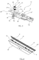
- FIG 4 shows cam arrangements 10, 10', 10", 10'" of a lock mechanism 12 in position on a closure sash 50, which may be a door or window sash.
- Cam arrangements 10, 10" may be equivalent to cam arrangement 10 shown in the preceding Figures.
- Cam arrangements 10', 10"' may be equivalent to cam arrangement 10' shown in the preceding Figures.
- Figures 5 and 6 show cam arrangement 10 and lock mechanism 12, in use, as part of a system for closing and/or securing a closure 50.
- the lock mechanism 12 shown in Figures 5 and 6 differs from lock mechanism 12 shown in the preceding Figures only in that the position of cam arrangements 10, 10' has been reversed. The operational use is substantially the same. Equivalent reference numerals have been used to aid understanding.
- Figures 5 and 6 show how the cam arrangement 10' of lock mechanism 12' may engage with a locking arrangement 100 which may, for example, be provided in a corresponding frame of the associated closure.
- the locking arrangement 100 comprises a series of elongate slots 102, 104a, 104b, 104c, 104d which are configured, in use, to engage with cams 14, 14', etc. of the lock mechanism 12 to close and/or secure the closure.
- slot 102 is configured to engage with cam arrangement 10'
- slot 104d is configured to engage with cam arrangement 10.
- Slots 104a, 104b and 104d may each be configured to engage with cam arrangements of further lock mechanisms, for example, on adjacent window or door sashes.
- the lock mechanism 12 is shown in a position prior to engagement with the locking arrangement 100.
- cam arrangement 10' is shown proximal to the slot 102 of locking arrangement 100.
- cam 14' of cam arrangement 10' is brought into contact with the slot 102, and in particular contact surface 103 of the slot 102.
- cam 14 of cam arrangement 10 can be brought into engagement with slot 104d, for example, to secure the closure. As is described in detail below, this may be performed through use of an operating handle.
- lower supporting arm 16b may be moved relative to upper supporting arm 16a causing the cam 14 of cam arrangement 10 to move towards and subsequently into contact with the slot 104d.
- Slot 38 in the upper supporting arm 16a allows the cam arrangement 10 to move with respect to the upper supporting arm 16a and engage with slot 104d, whilst cam arrangement 10' remains stationary (i.e. engaged with slot 102).
- slot 104d may include a contact surface, in the same way as slot 102 includes contact surface 103.
- lower supporting arm 16b is moved relative to upper supporting arm 16a, e.g. through rotation of an associated operating handle, causing the cam 14 of cam arrangement 10 to move away from and out of contact with the slot 104d.
- cam 14' of cam arrangement 10' is moved out of contact with the slot 102, and in particular contact surface 103 of the slot 102. This may be achieved through opening of the closure itself.
- the lock mechanism 12 additionally includes a gear arrangement 40.
- the gear arrangement 40 is operable to act on the supporting arms 16a, 16b of the supporting member 16 to cause relative movement thereof. For example, rotation of one or more gears of the gear arrangement 40 causes linear movement of one or both of the supporting arms 16a, 16b of the supporting member 16.
- the gear arrangement 40 includes an aperture 42 therein for receiving, for example, a spindle of an associated operating handle.
- rotation of the operating handle - causes simultaneous rotation of one or more gears of the gear arrangement 40 causing linear movement of one or both of the supporting arms 16a, 16b of the supporting member.
- rotation of the operating handle causes the lower supporting arm 16b to move linearly with respect to the upper supporting arm 16a, causing movement of the cam arrangement 10 towards or away from elongate slot 104d.
- adjusting the angular position of the cam 14 results in a change in the lateral and/or longitudinal position of the cam 14 with respect to the supporting member 16.
- altering the position of the cam in this sense also adjusts its position with respect to the locking arrangement 100.
- adjusting the position of the cam 14 in this way changes how the cam 14 engages with the contact surface of slot 104d which in turn changes the contact pressure between the closure 50 (in which the lock mechanism 12 is incorporated) and an associated frame (not shown) in which the locking arrangement 100 may be incorporated.
- the cam 14 may be brought into contact with different portions of the contact surface, or at a different contact pressure with the contact surface of the slot 104d depending on its lateral and longitudinal position with respect to the locking arrangement 100.
- Components of the cam arrangement 10 may be integrally formed, or may comprise separate components which are fixed together, e.g. by a fastening or fixing means.
- one or more components of the cam arrangement 10 may be riveted, for example via a spin riveting process.
- one or more components of the cam arrangement 10 may be fixed together using a retaining washer or a clip arrangement, for example.
- cam arrangement 10 is shown herein to comprise a cam 14 which is displaced outwardly to disengage the retention mechanism, it will be appreciated that the cam arrangement 10 may be configured in the opposite sense in that the cam 14 may be moveable to its first axial position from its second axial position to disengage the retention mechanism.
- the illustrated embodiments include the provision of a biasing member 18 in the form of a compressible wave washer which gives rise to the biasing force upon compression of the washer.
- a biasing member 18 in the form of a compressible wave washer which gives rise to the biasing force upon compression of the washer.
- biasing member may be used such as a resilient material, or a spring, for example.
- the biasing member may comprise an extendable biasing member which gives rise to the biasing force upon extension or stretching of the biasing member.
- the biasing member 18 may be omitted. Rather, the cam 14 may be moved between axial positions solely under the action of an operator/user of the cam arrangement 10. In such embodiments, the lower spacer 26 may be operable to act as an end stop to for the cam 14 - e.g. to prevent the cam 14 moving past its second axial position to a position where it projects more than a second distance from the upper surface 28 of the supporting member 16.
- the retention mechanism consists of a plurality of splines on an outer surface of the cam which are configured to engage with complementary splines on the lock mechanism 12.
- the retention mechanism may instead be configured to provide an interference fit between the cam 14 and a further component of the cam arrangement 10.
- a further component of the cam arrangement 10 may be provided with a plurality of complementary splines on a surface thereof, which may be on an inner surface thereof.
- the further component of the cam arrangement 10 may include a shaft to which the cam may be coupled.
- the coupling between the shaft and the cam may provide an interference fit for retaining the cam in its current angular position.
Landscapes
- Engineering & Computer Science (AREA)
- Mechanical Engineering (AREA)
- Structural Engineering (AREA)
- Closing And Opening Devices For Wings, And Checks For Wings (AREA)
Applications Claiming Priority (1)
| Application Number | Priority Date | Filing Date | Title |
|---|---|---|---|
| GB1907742.9A GB2584333B (en) | 2019-05-31 | 2019-05-31 | A cam arrangement |
Publications (1)
| Publication Number | Publication Date |
|---|---|
| EP3744935A1 true EP3744935A1 (de) | 2020-12-02 |
Family
ID=67385901
Family Applications (1)
| Application Number | Title | Priority Date | Filing Date |
|---|---|---|---|
| EP20275089.9A Pending EP3744935A1 (de) | 2019-05-31 | 2020-05-18 | Nockenanordnung |
Country Status (2)
| Country | Link |
|---|---|
| EP (1) | EP3744935A1 (de) |
| GB (1) | GB2584333B (de) |
Families Citing this family (1)
| Publication number | Priority date | Publication date | Assignee | Title |
|---|---|---|---|---|
| DE102021201882A1 (de) | 2021-02-26 | 2022-09-01 | Roto Frank Fenster- und Türtechnologie GmbH | Einfache Steuerzapfenbefestigung |
Citations (5)
| Publication number | Priority date | Publication date | Assignee | Title |
|---|---|---|---|---|
| DE7313820U (de) * | 1973-04-12 | 1973-10-31 | Fa Aug Bilstein | Kantengetriebe mit getriebestange und darauf befestigtem verriegelungsbolzen |
| DE2705802A1 (de) * | 1977-02-11 | 1978-08-17 | Winkhaus Fa August | Verriegelungsvorrichtung fuer fenster, tueren oder dergleichen |
| FR2398865A2 (fr) * | 1977-07-26 | 1979-02-23 | Winkhaus Fa August | Dispositif de verrouillage pour fenetres, portes et elements de fermeture analogues |
| DE3243858A1 (de) * | 1982-11-26 | 1984-05-30 | Fa. Aug. Winkhaus, 4404 Telgte | Verriegelungskloben-anordnung |
| DE2759925C2 (de) * | 1977-02-11 | 1989-11-02 | Fa. Aug. Winkhaus, 4404 Telgte | Verriegelungsvorrichtung für Fenster, Türen od.dgl. |
Family Cites Families (3)
| Publication number | Priority date | Publication date | Assignee | Title |
|---|---|---|---|---|
| DE10158359A1 (de) * | 2001-11-28 | 2003-06-12 | Winkhaus Fa August | Beschlagteil für einen Treibstangenbeschlag |
| DE102005000099A1 (de) * | 2005-07-28 | 2007-02-01 | Aug. Winkhaus Gmbh & Co. Kg | Beschlagteil für einen Treibstangenbeschlag |
| ITBO20110168A1 (it) * | 2011-03-31 | 2012-10-01 | Gsg Int Spa | Terminale di chiusura per porte o finestre. |
-
2019
- 2019-05-31 GB GB1907742.9A patent/GB2584333B/en active Active
-
2020
- 2020-05-18 EP EP20275089.9A patent/EP3744935A1/de active Pending
Patent Citations (5)
| Publication number | Priority date | Publication date | Assignee | Title |
|---|---|---|---|---|
| DE7313820U (de) * | 1973-04-12 | 1973-10-31 | Fa Aug Bilstein | Kantengetriebe mit getriebestange und darauf befestigtem verriegelungsbolzen |
| DE2705802A1 (de) * | 1977-02-11 | 1978-08-17 | Winkhaus Fa August | Verriegelungsvorrichtung fuer fenster, tueren oder dergleichen |
| DE2759925C2 (de) * | 1977-02-11 | 1989-11-02 | Fa. Aug. Winkhaus, 4404 Telgte | Verriegelungsvorrichtung für Fenster, Türen od.dgl. |
| FR2398865A2 (fr) * | 1977-07-26 | 1979-02-23 | Winkhaus Fa August | Dispositif de verrouillage pour fenetres, portes et elements de fermeture analogues |
| DE3243858A1 (de) * | 1982-11-26 | 1984-05-30 | Fa. Aug. Winkhaus, 4404 Telgte | Verriegelungskloben-anordnung |
Also Published As
| Publication number | Publication date |
|---|---|
| GB201907742D0 (en) | 2019-07-17 |
| GB2584333A (en) | 2020-12-02 |
| GB2584333B (en) | 2023-04-26 |
Similar Documents
| Publication | Publication Date | Title |
|---|---|---|
| US6981724B2 (en) | Multi-point lock assembly | |
| US9140041B2 (en) | Compression latch | |
| EP3929386B1 (de) | Entlüftungsbediener | |
| EP1809841A2 (de) | Verarbeitung von über kommunikationsnetze zu übertragenden nachrichten | |
| EP2692969B1 (de) | Getriebe eines Treibstangenbeschlages, Treibstangenbeschlag mit einem derartigen Getriebe sowie Fenster, Tür oder dergleichen mit einem derartigen Treibstangenbeschlag | |
| KR101842834B1 (ko) | 폴딩도어 락 잠금장치 | |
| EP1111175B1 (de) | Verschluss für Gerätetüren | |
| EP2762660A2 (de) | Riegelaufnahmeteil | |
| EP3976912B1 (de) | Nockenanordnung | |
| EP3411547B1 (de) | Vorreiberverschluss mit einem in unterschiedlicher höhe an einer schliesswelle fixierbaren verschlusselement | |
| EP3744935A1 (de) | Nockenanordnung | |
| EP3034719B1 (de) | Betätigungsvorrichtung für einen verriegelungsmechanismus einer tür oder eines fensters | |
| GB2253241A (en) | An espagnolette mechanism | |
| US11725417B1 (en) | Fenestration cam lock assemblies and methods | |
| WO2007140876A1 (de) | Band mit justierung | |
| CN216240193U (zh) | 风撑装置及使用该风撑装置的窗户 | |
| EP3480393B1 (de) | Vorrichtung und verfahren zur montage eines griffes an einer tür- oder einem fenster | |
| DE3636236A1 (de) | Panikverschluss fuer zweifluegelige tueren | |
| EP1256679B1 (de) | Verschluss für Fensterläden | |
| DE10056607C1 (de) | Fehlbedienungssperre für Treibstangenbeschläge | |
| EP2199529B1 (de) | Schirmanordnung | |
| RU2743215C2 (ru) | Фурнитура приводной штанги | |
| CN215889606U (zh) | 用于诸如窗、门等结构元件的操纵手柄 | |
| EP0143237B1 (de) | Griffbeschlag für Treibstangenbeschläge von Fenstern, Türen oder dergleichen | |
| DE202004004769U1 (de) | Beschlaganordnung |
Legal Events
| Date | Code | Title | Description |
|---|---|---|---|
| PUAI | Public reference made under article 153(3) epc to a published international application that has entered the european phase |
Free format text: ORIGINAL CODE: 0009012 |
|
| STAA | Information on the status of an ep patent application or granted ep patent |
Free format text: STATUS: THE APPLICATION HAS BEEN PUBLISHED |
|
| AK | Designated contracting states |
Kind code of ref document: A1 Designated state(s): AL AT BE BG CH CY CZ DE DK EE ES FI FR GB GR HR HU IE IS IT LI LT LU LV MC MK MT NL NO PL PT RO RS SE SI SK SM TR |
|
| AX | Request for extension of the european patent |
Extension state: BA ME |
|
| STAA | Information on the status of an ep patent application or granted ep patent |
Free format text: STATUS: REQUEST FOR EXAMINATION WAS MADE |
|
| 17P | Request for examination filed |
Effective date: 20210602 |
|
| RBV | Designated contracting states (corrected) |
Designated state(s): AL AT BE BG CH CY CZ DE DK EE ES FI FR GB GR HR HU IE IS IT LI LT LU LV MC MK MT NL NO PL PT RO RS SE SI SK SM TR |
|
| STAA | Information on the status of an ep patent application or granted ep patent |
Free format text: STATUS: EXAMINATION IS IN PROGRESS |
|
| 17Q | First examination report despatched |
Effective date: 20240417 |